

Page 1
*819
6663
*
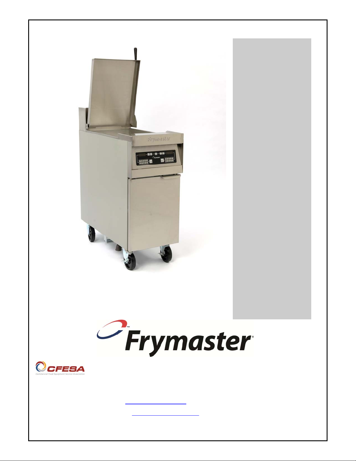
FE155 Rethermalizer
Installation and Operation Manual
Triton™ Electric
PRINTED IN THE USA
Frymaster, a member of the Commercial Food Equipment Service Association, recommends
using CFESA Certified Technicians.
24-Hour Service Hotline 1-800-551-8633 11/2016
www.frymaster.com
Email: service@frymaster.com
Page 2
Please read all sections of this manual and retain for future reference.
NOTICE
This appliance is intended for professional use only and is to be operated by qualified
personnel only. A Factory Authorized Servicer (FAS) or other qualified professional should
perform installation, maintenance, and repairs. Installation, maintenance, or repairs by
unqualified personnel may void the manufacturer’s warranty.
NOTICE
Drawings and photos used in this manual are intended to illustrate operational, cleaning and
technical procedures and may not conform to onsite management operational procedures.
NOTICE
IF, DURING THE WARRANTY PERIOD, THE CUSTOMER USES A PART F OR THIS MANITOWOC
FOOD SERVICE EQUIPMENT OTHER THAN AN UNMODIFIED NEW OR RECY CLED PART
PURCHASED DIRECTLY FROM FRYMASTER/DEAN, OR ANY OF ITS AUTHORIZED SERVICE
CENTERS, AND/OR THE PART BEING USED IS MODIFIED FROM ITS ORIGINAL
CONFIGURATION, THIS WARRANTY WILL BE VOID. FURTHER, FRYMASTER/DEAN AND ITS
AFFILIATES WILL NOT BE LIABLE FOR ANY CLAIMS, DAMAGES OR EXPENSES INCURRED BY
THE CUSTOMER WHICH ARISE DIRECTLY OR INDIRECTLY, IN WHOLE OR IN PART, DUE TO
THE INSTALLATION OF ANY MODIFIED PART AND/OR PART RECEIVED FROM AN
UNAUTHORIZED SERVICER.
DANGER
Improper installation, adjustment, maintenance or service, and unauthorized alterations or
modifications can cause property damage, injury, or death. Read the installation, operating and
service instructions thoroughly before installing or servicing this equipment.
DANGER
Adequate means must be provided to limit the movement of this appliance. Single fryers
equipped with legs must be stabilized by installing anchor straps. All fryers equipped with
casters must be stabilized by installing restraining chains.
DANGER
The front ledge of the unit is not a step. Do not stand on the rethermalizer. Serious injury can
result from slips or contact with the hot water.
DANGER
Do not store or use gasoline or other flammable vapors and liquids in the vicinity of this or any
other cooking appliance.
WARNING
No structural material on the fryer should be altered or removed to accommodate placement of
the fryer under a hood. Questions? Call the Frymaster Service Hotline at 1-800-551-8633.
ii
Page 3
WARNING
Do not bang fry baskets or other utensils on the fryer’s joiner strip. The strip is present to seal
the joint between the frypot. Banging fry baskets on the strip to dislodge shortening will distort
the strip, adversely affecting its fit. It is designed for a tight fit and should only be removed for
cleaning.
IMPORTANT
Safe and satisfactory operation of Frymaster equipment depends upon its proper installation.
Installation MUST conform with local codes, or in the absence of local codes, to European
Community (CE) Standards.
COMPUTERS
FCC
This device complies with Part 15 of the FCC rules. Operation is subject to the following two conditions:
1) This device may not cause harmful interference, and 2) This device must accept any interfere nce
received, including interference that may cause undesired operation. While this device is a verified Class
A device, it has been shown to meet the Class B limits.
CANADA
This digital apparatus does not exceed the Class A or B limits for radio noise emissions as set out by the
ICES-003 standard of the Canadian Department of Communications.
Cet appareil numerique n’emet pas de bruits radioelectriques depassany les limites de classe A et B
prescrites dans la norme NMB-003 edictee par le Ministre des Communcations du Canada.
DANGER
THIS PRODUCT CONTAINS CHEMICALS KNOWN TO THE STATE OF CALIFORNIA TO CAUSE
CANCER AND/OR BIRTH DEFECTS OR OTHER REPRODUCTIVE HARM.
Operation, installation, and servicing of this product could expose you to airborne particles of
glasswool or ceramic fibers, crystalline silica, and/or carbon monoxide. Inhalation of airborne
particles of glasswool or ceramic fibers is known to the State of California to cause cancer.
Inhalation of carbon monoxide is known to the State of California to cause birth defects or other
reproductive harm.
NOTICE
The Commonwealth of Massachusetts requires any and all gas products and/or electrical
products attached to a water supply to be installed by a licensed plumber or pipe fitter.
DANGER
Do not use a water jet to clean this appliance.
WARING
Raise the lid slowly. Trapped steam may escape from beneath the lid.
iii
Page 4
NOTICE
All units shipped without factory supplied cords and plug assemblies must be
hardwired using flexible conduit to the terminal block located on the rear of the unit.
These units should be wired to NEC specifications. Hardwired units must include
installation of restraint devices.
DANGER
Adequate means must be provided to limit the movement of this appliance without
depending on or transmitting stress to the electrical conduit. A restraint kit is provided
with the fryer. If the restraint kit is missing contact your local Frymaster Authorized
Servicer (FAS) for part number 810-3574.
NOTICE
If this equipment is wired directly into the electrical power supply, a means for
disconnection from the supply having a contact separation of at least 3-mm in all poles
must be incorporated in the fixed wiring.
NOTICE
This equipment must be positioned so that the plug is accessible unless other means
for disconnection from the power supply (e.g., a circuit breaker) is provided.
NOTICE
If the electrical power supply cord is damaged, it must be replaced by a Factory
Authorized Servicer technician or a similarly qualified person in order to avoid a hazard.
NOTICE
If this appliance is permanently connected to fixed wiring, it must be connected by
means of copper wires having a temperature rating of not less than 167°F (75°C).
iv
Page 5

Triton™ FE155 Rethermalizer
TABLE OF CONTENTS
PAGE
CHAPTER 1: General Information
Parts Ordering and Service Information ......................................................................................... 1-1
Safety Information .......................................................................................................................... 1-1
Equipment Description ................................................................................................................... 1-2
Installation, Operating, and Service Personnel ............................................................................... 1-2
Shipping Damage Claim Procedure ............................................................................................... 1-3
CHAPTER 2: Installation Instructions
General Installation Requirements ................................................................................................. 2-1
Caster/Leg Installation .................................................................................................................... 2-2
Pre-Connection Preparations .......................................................................................................... 2-2
Connection to Electrical Supply ..................................................................................................... 2-3
Power Requirements ....................................................................................................................... 2-4
Wiring Diagrams ............................................................................................................................ 2-5
CHAPTER 3: Operating Instructions
Annotated View .............................................................................................................................. 3-1
Controller/Operation/Programming ............................................................................................... 3-2
Start Up Procedure ......................................................................................................................... 3-3
Boil Out Procedure ......................................................................................................................... 3-4
CHAPTER 4: Preventive Maintenance
Daily Service Checks ..................................................................................................................... 4-1
Quarterly Checks ............................................................................................................................ 4-1
Annual Service Checks ................................................................................................................... 4-2
CHAPTER 5: Operator Troubleshooting
Introduction .................................................................................................................................... 5-1
Troubleshooting Guide ................................................................................................................... 5-2
v
Page 6

CHAPTER 1: Introduction
1.1 Parts Ordering and Service Information
In order to assist you as quickly as possible, the Frymaster Authorized Servicer (FAS) or Service
Department representative requires certain information about your equipment. Most of this information is printed on a data plate affixed to the inside of the door.
Parts orders may be placed directly with your local FAS or distributor. A list of Frymaster Factory
Authorized Servicers (FAS’s) is located on the Frymaster website at www.frymaster.com/service.
If you do not have access to this list, contact the Frymaster Technical Service Department at 1-800551-8633 or 1-318-865-1711.
When ordering parts, the following information is required:
Model Number:
Serial Number:
Voltage:
Item Part Number:
Service information may be obtained by contacting your local FAS/Distributor. Information may
also be obtained by calling the Frymaster Technical Service Department at 1-800-551-8633 or
1-318-865-1711. When requesting service, please have the following information ready:
In addition to the model number, serial number, and voltage, please be prepared to describe the nature of the problem and have ready any other information that you think may be helpful in solving
your problem.
RETAIN AND STORE THIS MANUAL IN A SAFE PLACE FOR FUTURE USE.
Quantity Needed:
Model Number:
Serial Number:
Voltage:
1.2 Safety Information
Before attempting to operate your unit, read the instructions in this manual thoroughly.
Throughout this manual, you will find safety notations enclosed in double-bordered boxes similar
to the ones illustrated below and on the following page.
CAUTION
CAUTION boxes contain information about actions or conditions that may cause or
result in a malfunction of your system.
WARNING
WARNING boxes contain information about actions or conditions that may cause or
result in damage to your system, and which may cause your system to malfunction.
1-1
Page 7

DANGER
DANGER boxes contain information about actions or conditions that may cause or
result in injury to personnel, and which may cause damage to your system and/or
cause your system to malfunction.
1.3 Equipment Description
The FE155 Series is specifically designed to rethermalize meats, sauces, and other vacuum packaged foods at a safe temperature range.
The system features a controller and an easy to clean vat. Each unit can rethermalize up to 30 lbs.
(13.6 kg) of food an hour.
The cookpot is safeguarded against boil-over by a standpipe overflow drain, and comes with a 1”
cookpot drain for fast, clog-free emptying. The unit has a rethermalizing/cooking area of 14.25” x
19” (362mm x 482mm) and holds 16.5 gallons (62 liters) of water.
1.4 European Community (CE) Specific Information
The European Community (CE) has established certain specific standards
regarding equipment of this type. Whenever a difference exists between CE
CE Standard
and non-CE standards, the information or instructions concerned are identified with a shadowed box like the one at right.
1.5 Installation, Operating, and Service Personnel
Operating information for Frymaster equipment has been prepared for use by qualified and/or authorized personnel only, as defined in Section 1.6.
All installation and service on Frymaster equipment must be performed by qualified, certified, licensed, and or/authorized installation or service personnel, as defined in Section 1.5.
1.6 Definitions
QUALIFIED AND/OR AUTHORIZED OPERATING PERSONNEL
Qualified/authorized operating personnel are those who have carefully read the information in this
manual and have familiarized themselves with the equipment functions, or who have had previous
experience with the operation of the equipment covered in this manual.
QUALIFIED INSTALLATION PERSONNEL
Qualified installation personnel are individuals, or firms, corporations, or companies which, either
in person or through a representative, are engaged in and are responsible for the installation of
electrical appliances. Qualified personnel must be experienced in such work, be familiar with all
electrical precautions involved, and have complied with all requirements of applicable national and
local codes.
1-2
Page 8

QUALIFIED SERVICE PERSONNEL
Qualified service personnel are those that are familiar with Frymaster equipment and who have
been authorized by Frymaster to perform service on Frymaster equipment. All authorized service
personnel are required to be equipped with a complete set of service and parts manuals, and to stock
a prescribed minimum amount of Frymaster equipment parts.
A list of Frymaster Factory Authorized Servicers (FAS’s) is located on the Frymaster website at
www.frymaster.com/service. Failure to use qualified service personnel will void the Frymaster
Warranty on your equipment.
1.7 Shipping Damage Claim Procedure
Your Frymaster equipment was carefully inspected and packed before leaving the factory. The
transportation company assumes full responsibility for safe delivery upon acceptance of the equipment for transport.
What to do if your equipment arrives damaged:
1. File a claim for damages immediately, regardless of the extent of damages.
2. Inspect for and record all visible loss or damage and ensure that this information is noted on
the freight bill or express receipt and is signed by the person making the delivery.
3. Concealed loss or damage that was unnoticed until the equipment was unpacked should be
recorded and reported to the freight company or carrier immediately upon discovery. A concealed damage claim must be submitted within 15 days of the date of delivery. Ensure that the
shipping container is retained for inspection.
FRYMASTER DOES NOT ASSUME RESPONSIBILITY
FOR DAMAGE OR LOSS INCURRED IN TRANSIT.
1-3
Page 9

CHAPTER 2: Installation Instructions
2.1 General Installation Requirements
PROPER INSTALLATION IS ESSENTIAL FOR EFFICIENT, TROUBLE-FREE
OPERATION OF YOUR RETHERMALIZER. ANY UNAUTHORIZED ALTERATIONS
MADE TO THIS EQUIPMENT WILL VOID THE FRYMASTER WARRANTY.
Upon arrival, inspect the equipment carefully for visible or concealed damage. Report any damage
found immediately (see Shipping Damage Claim Procedure in Chapter 1).
NATIONAL CODE REQUIREMENTS
This equipment is to be installed in compliance with the Basic Plumbing Code of the Building Officials and Code Administrators International, Inc. (BOCA) and the Food Service Sanitation Manual
of the U.S. Food and Drug Administration.
AUSTRALIAN REQUIREMENTS
To be installed in accordance with AS 5601, local authority, gas, electricity, and any other relevant
statutory regulations.
NOTICE: The Commonwealth of Massachusetts requires any and all products connected to the gas or
water system to be installed by a licensed plumber or pipe fitter.
ELECTRICAL GROUNDING REQUIREMENTS
All electrically operated appliances must be grounded in accordance with all applicable national and
local codes, and, where applicable, CE codes. All units (cord connected or permanently connected)
should be connected to a grounded power supply system. A wiring diagram is located on the inside
of the unit door. Refer to the rating plate on the inside of the door for proper voltages.
FCC COMPLIANCE
The user is cautioned that any changes or modifications to Frymaster computers not expressly approved by the party responsible for compliance could void the user’s authority to operate the equipment. Frymaster computers have been tested and found to comply with the limits for a Class A digital device, pursuant to Part 15 of the FCC rules. While these devices are verified as Class A devices,
they have been shown to meet the Class B limits. These limits are designed to provide reasonable
protection against harmful interference when the equipment is operated in a commercial environment. This equipment generates, uses, and can radiate radio frequency energy and, if not installed
and used in accordance with the instruction manual, may cause harmful interference to radio communications. Operation of the equipment in a residential area is likely to cause harmful interference
in which case the user will be required to correct the interference at his own expense.
If necessary, the user should consult the dealer or an experienced radio and television technician for
additional suggestions.
2-1
Page 10

The user may find the booklet “How to Identify and Resolve Radio-TV Interference Problems” helpful. It is prepared by the Federal Communications Commission and is available from the U.S. Government Printing Office, Washington, DC 20402, Stock No. 004-000-00345-4.
2.2 Caster/Leg Installation
Depending upon the specific configuration ordered, your unit might have been shipped without installed casters or legs. If casters or legs are installed, you may skip this section and proceed to Section 2.3, Pre-Connection Preparations.
If your unit requires the installation of casters or legs, install them in accordance with the instructions included in your accessory package. NOTE: Use only the casters or legs provided
by Frymaster for this equipment.
When the rethermalizer is leveled in its final position, install the restraints provided with the unit to
limit its movement so that it does not depend on or transmit stress to the electrical conduit or connection. Install the restraints in accordance with the provided instructions (see illustration below). If
the restraints are disconnected for service or other reasons, they must be reconnected before the unit
is used.
DANGER
Adequate means must be provided to limit the movement of this appliance without
depending on or transmitting stress to the electrical conduit. A restraint kit is provided with the fryer. If the restraint kit is missing contact your local Frymaster Authorized Service Agency (ASA) for part number 810-3574.
2.3 Pre-Connection Preparations
After the unit has been positioned in the area where it will be used, ensure the following have been
accomplished before connecting the unit to the electrical power source:
1. This equipment must be stabilized by installing restraining chains on units equipped with casters
or anchor straps on units equipped with legs. Follow the instructions shipped with the casters/legs to properly install the chains or straps.
2. Level units equipped with legs by screwing the legs out approximately one inch, then adjusting
them so that the unit is level.
For units equipped with casters, there are no built-in leveling devices. The floor where the unit
is to be installed must be level.
2-2
Page 11

3. If so equipped, connect the water hose(s) to the fitting(s) at the rear of the unit and connect the
unit to the water supply.
DANGER
Do not use a water jet to clean this appliance.
CAUTION
Incoming water pressure for all units should be approximately 40 PSI (2.8 kg/cm2)
(275.79 kPa).
DANGER
The maximum allowable incoming water pressure for all units is 80 PSI (5.6 kg/cm2)
(551.6 kPa).
The maximum allowable incoming water temperature for all units is 140ºF (60ºC).
WARNING
To prevent back flushing, the connection piping should be installed with a vacuum breaker
or means of providing an air gap 1” (2.54 cm) above the cookpot rim.
NOTE: On units equipped with water hoses, the hoses come with a quick-disconnect coupling.
The quick disconnect may be attached to the unit or to the water supply line, or it may be left off
entirely, whichever you prefer. If the unit is to be moved frequently (for cleaning or preventive
maintenance), Frymaster recommends installing flexible water lines. If the cooker is hardplumbed then moved, the connections may loosen and eventually cause leaks. Whichever option
is chosen, Teflon thread-seal tape, Loctite™ PST56765, or equivalent thread sealer must be
used when installing the fittings.
NOTE: Depending on specific model ordered, either hot {max 140°F (60°C}) or cold water, or
both, may be connected to the unit. If available, connecting hot water will minimize the time
required to bring the unit to operating temperature when filling with fresh water.
6. Connect the desired drain plumbing to the drain valve. NOTE: Ensure drain plumbing is
connected in accordance with local codes. Waste water from the water bath unit
should not be discharged directly below the appliance. Rising steam can harm the
cabinet and the electrical components.
2.4 Connecting to the Electrical Supply
DANGER
This unit must be connected to the voltage and phase specified on the rating and serial
number plate located on the inside of the equipment door. To determine the appropriate
wire size, refer to the POWER REQUIREMENTS chart at the bottom of this page.
1. If the unit is not equipped with an installed power cord, open the door and remove the contactor
box cover. Position the unit to gain access to the rear and remove the lower back panel.
2. Install a CE-approved harmonized cord rated for a minimum of 32 amps
at 415 VAC minimum with 5 wires, including a neutral and ground. It
CE Standard
must be oil and water resistant. Make the connections in accordance with
the wiring diagram below.
2-3
Page 12

3. Install the supplied strain relief, Oflex SKZ21 (8071210), which has a wire range of 15 to 23
mm, and replace the lower back panel and contactor box cover.
4. Install a CE-approved plug rated for a minimum of 32 amps at 415 VAC. In must be a 3-phase,
5-wire type with neutral and ground and be oil and water resistant.
Power Requirements
Use copper wire ONLY, suitable for at least 170ºF (75ºC)
ELECTRIC COOKER MODEL FE155
Amps
Volts Phase kW
(per leg)
208 Single 8 38.7 8
220 Single 9 40.9 8
208 3 8 22.3 10
220 3 9 23.6 10
240 Single 10.7 44.6 6
440 Single 9 20.5 10
240 3 10.7 25.8 10
440 3 9 11.8 12
480 Single 10.7 22.3 10
480 3 10.7 12.9 12
Minimum
Wire Size
CE Power Requirements
Use copper wire ONLY, suitable for at least 75ºC
ELECTRIC COOKER MODEL FE155
Volts Phase kW
Amps
(per leg)
Minimum
Wire Size
220/400 3 9.8 14.3 4.11 mm
2-4
Page 13

Field Connection Wiring Diagrams
2-5
Page 14

CHAPTER 3: Operating Instructions
3.1 Finding Your Way Around the FE155
FE155
Lid
Controller
Cookpot
Controller
Upper Level Float Switch
Drain
Element
Low Level Float Switch
FE155 Vat
Main Power Switch
Drain handle
Cabinet Interior
Overflow
Inlet
3-1
Page 15

3.2 Controller
/
This equipment uses a specialized controller.
Controller Operation
• Ensure the main power switch (behind cabinet door) is on.
• Press either ON/OFF button to turn the controller on.
• The controller displays LO as it rises to the setpoint.
• At setpoint, the controller displays alternate between dashed lines and S inn.
• Enter time or temperature changes (see programming instructions below).
• Press a Temperature key to toggle display to actual temperature on the left, setpoint on the
right. Press again to toggle back.
Simmer
• Place product in vat and press desired timer key. Display alternates
between S inn and remaining cook time.
• COOC appears and an alarm sounds when the cook time elapses. Cook
cycles won’t start if the controller is displaying LO.
• Remove the product and press the timer key to halt the alarm.
Boil/Boost
• Press the boil/ boost key. Most rethermalizing is done at 190-
195°F, the simmer temperature range. This key allows a quick
change to boiling temperature without changing the
controller.
• Display changes to boil.
• Temperature rises to boil from simmer in about 7 minutes.
NOTE: Pressing the boil/boost key
with the controller OFF produces a
CodE display, which is used in initial
programming. ON/OFF keys are
inactive. Press any other key four
times to clear display and reactivate ON/OFF keys.
NOTE: Controller returns to simmer mode
if a boil cook cycle is
not initiated within 15
minutes of pressing
the boil
• Follow programming instructions to change cook time if
necessary.
• Place product in vat and press the desired timer key.
• COOC appears and an alarm sounds when the cook time elapses.
• Remove the product and press the timer key to halt the alarm and return to simmer mode.
boost key.
3-2
Page 16

Programming
• Cooking Temperature change: Press the temperature key until the current temperature is
displayed on right side. Enter the desired temperature with the right key pad.
• An illuminated dot between the last digit and the F indicates the change was accepted.
Temperatures below 125°F and above 210°F can’t be entered. The controller will default to
its lowest setting, 125°F, upon a lower temperature entry and to its highest setting, 210°F,
upon a higher temperature entry.
• Cooking Time change: Press the temperature key until the display alternates between S inn
and a dashed line. Enter the desired time, in minutes and seconds, on the key pad. Press the
timer key to ensure the desired time is in place. Press the timer key a second time to stop the
timer.
WARING
Raise the lid slowly. Trapped steam may escape from beneath the lid.
CAUTION
The electronic circuitry in your controller can be affected adversely by current
fluctuations and electrical storms. Should it fail to function or program properly for
no apparent reason, the controller should be reset by unplugging the controller
harness from the rear of the controller and plugging it back into the controller. This
could prevent a service call.
3.3 Start-Up Procedure
CAUTION
If this is the first time the unit is being used after installation, refer to Section 3.5,
Boiling-Out the Cookpot.
1. Before turning the equipment on, ensure that:
• The unit is connected to the water supply.
• The water supply is turned on.
• The unit is plugged into an outlet of appropriate voltage (check rating plate to verify).
• The electrical power supply to the equipment is turned on.
• Drain in place.
• The main power switch is on.
2. Press the controller power switch.
If the cookpot is not full, the AutoFill will add water. When the water covers the upper float
switch, the AutoFill solenoid valve will cut off the water. If the water level drops below the
upper float switch during operation, the solenoid valve will open and add water to the cookpot.
3-3
Page 17

When the water level is above the lower float switch, the elements will energize. When the unit
reaches setpoint, the display will alternate between dashed lines and S inn. Pressing either
temperature key displays the actual temperature on the left, setpoint on the right.
3.4 Draining
WARNING
1. Allow the water to cool.
2. Turn the main power switch off.
3. Slowly open the drain valve.
4. Close the drain valve and turn on the main power
Use extreme caution if draining hot
water. Severe burns can be caused
by hot water and steam. Follow all
restaurant safety procedures.
switch to refill the unit.
3.5 Boiling-Out the Cookpot
To ensure that the vat is free of any contamination, the vat must be
boiled out before first use.
1. Close the drain valve and fill the cookpot with a solution of cold
water and 1 cup of detergent.
2. Place the unit into operation.
NOTE: The water inlet is
controlled by the main
power switch. It must be off
during draining and cleaning to ensure the vat
doesn’t refill unexpectedly.
3. Allow the unit to simmer for one hour.
4. Turn the unit off with the main power switch and allow the solution to cool. Add cold water and
stir. Drain the solution and clean the vat thoroughly.
5. Rinse the vat at least twice by filling with clean water and draining.
3.6 Shutting the FE155 Down
1. Turn the unit off by pressing the main power switch in the cabinet.
2. If shutting down at the end of the day, drain and clean the cookpot and lower the lid.
3-4
Page 18

CHAPTER 4: Preventive Maintenance
4.1 Daily Checks and Services
Inspect Cooking System and Accessories for Damage
Look for loose or frayed wires and cords, leaks, foreign material in cookpot or inside cabinet, and
any other indications that the rethermalizer and accessories are not ready and safe for operation.
Clean Cabinet Inside and Out
Clean inside the cabinet with a dry, clean cloth. Wipe all accessible metal surfaces and components
to remove accumulations of oil, dust, or cooking residue.
Clean the outside of the cabinet with a clean cloth dampened with dishwashing detergent, removing
oil, dust, or cooking residue.
DANGER
Never attempt to clean this equipment during the rethermalizing/cooking process or
when the cookpot is filled with hot water and/or food products.
Clean Float Switch Assemblies, Vat
Press the controller power switch to the OFF position.
Clean the float switches with a solution of detergent
and warm water. A Scotchbrite™ or equivalent nylon
pad may be used to scrub away any accumulated
mineral deposits. Verify that both floats move freely
Hi-level float
switch
up and down on the rod. Using a Scotchbrite™ or
similar abrasive pad and a solution of detergent and
warm water, clean the inside of the vat, paying
particular attention to the elements.
Rinse the vat thoroughly with clean water at least twice.
4.2 Quarterly Checks and Services
Check Controller Set Point Accuracy
1. Fill the cookpot with water. Press the controller power switch, and allow the unit to heat to
setpoint. Insert a good-grade thermometer or pyrometer probe into the cookpot, with the end
touching the temperature probe at the lower right front of the cookpot.
2. When the controller displays a series of four dashes, press the switch to show the temperature.
The measured temperature should be within ± 5ºF (2ºC) of the displayed water temperature. If
the reading is outside that range, contact an Factory Authorized Servicer (FAS) for assistance.
Probe
Hi-limit
Low-level
float switch
4-1
Page 19

5.3 Periodic/Annual Checks
Frymaster recommends that the unit be inspected annually by a Factory Authorized Servicer for the
following checks and adjustments:
• Verify that the heating element wires are in good condition and that leads have no visible fraying
or insulation damage.
• Verify that heating elements are in good condition with no build-up. Inspect the elements for
signs of extensive dry-firing.
• Verify that the float switches are in good working order and free of debris and build-up.
• Verify the heating-element amp-draw is within the allowed range as indicated on the appliance’s
rating plate.
• Verify that the temperature and high-limit probes are properly connected, tightened and func-
tioning properly, and that mounting hardware and probe guard are present and properly installed.
• Verify that component box and contactor box components (i.e. controller/controller, relays, in-
terface boards, transformers, contactors, etc.) are in good condition and free from moisture buildup, rust and other debris.
• Verify that component box and contactor box wiring connections are tight and that wiring is in
good condition.
• Verify that all safety features (i.e. contactor shields, drain safety switches, reset switches, etc.)
are present and functioning properly.
• Verify that the frypot/cookpot is in good condition and free of leaks and that the frypot/cookpot
insulation is in serviceable condition.
• Verify that all wiring harnesses and connections are tight and in good condition.
4-2
Page 20

CHAPTER 5: Troubleshooting\Inspection
5.1 Introduction
This chapter provides an easy reference guide to the more common problems that may occur during
the operation of this equipment. The troubleshooting guide is intended to help you correct, or at
least accurately diagnose, problems with the equipment. Although the chapter covers the most
common problems reported, you may encounter a problem not covered. In such instances, the
Frymaster Technical Service Department will help you identify and resolve the problem.
When troubleshooting a problem, always use a process of elimination, starting with the simplest
solution and working through to the most complex. Never overlook the obvious and try to establish
a clear idea of why the problem occurred.
If the troubleshooting and corrective actions in this chapter do not solve the problem, the problem is
probably beyond the scope of most operators. Call your Factory Authorized Servicer for assistance.
If you have doubts as to the proper action to take, do not hesitate to call the Frymaster Technical
Service Department or your local Frymaster Authorized Servicer for assistance.
Before calling a servicer or the Frymaster HOTLINE (1-800-551-8633):
• Verify that electrical cords are plugged in and that circuit breakers are on.
• Verify that water supply valves are open and that drain valves are fully closed.
DANGER
Hot water can cause severe burns. Never attempt to move this equipment when
filled with hot water or to transfer hot water from one container to another.
DANGER
Use extreme care when performing electrical circuit tests. Live circuits will be
exposed.
WARNING
Inspection, testing, and repair of electrical components should be performed only by
qualified service personnel. The equipment should be unplugged when servicing,
except when electrical tests are required.
5-1
Page 21

5.2 Operator Troubleshooting Guide
PROBLEM POSSIBLE CAUSES CORRECTIVE ACTION
Controller does not
activate.
A. No power to unit. A. Turn on circuit breaker.
B. Controller not turned on. B. Press controller ON/OFF key.
C. Main power switch off. C. Turn main power switch on.
A. Water not turned on. A. Turn water on.
Autofill does not add
water.
Autofill does not shut
off when the cookpot
is full.
Water will not heat
(controller is on, water
is at normal level, but
LO is not showing on
the controller).
Water will not heat
(water above lower
water level sensor and
LO is showing on the
controller).
Water heats but does
not reach setpoint.
Timer does not count
down.
B. Upper float stuck in up
position.
C. Malfunctioning solenoid
valve.
A. Dirty/sticking upper float
switch.
B. Malfunctioning solenoid
valve.
A. Dirty/sticking lower float
switch.
A. Defective controller. A. Call FAS.
B. Malfunctioning element
or other component in
heating system.
A. Defective controller. A. Call FAS.
B. Malfunctioning element. B. Call FAS
A. Operator error. A. Push a product button.
B. Defective controller. B. Call FAS
B. Clean float switch assembly (see
Section 4.1).
C. Call FAS.
A. Clean float switch assembly (see
Section 4.1).
B. Call FAS.
A. Clean float switch assembly (see
Section 4.1).
B. Call FAS.
5-2
Page 22

Frymaster, L.L.C., 8700 Line Avenue, Shreveport, Louisiana 71106
TEL 1-318-865-1711 FAX (Tech Support) 1-318-219-7135
PRINTED IN THE UNITED STATES
SERVICE HOTLINE
1-800-551-8633
819-6663
11/2016
 Loading...