

Page 1
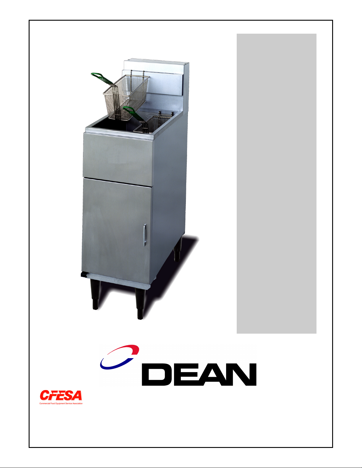
Super Runner 38 Series Electric Fryers
Installation & Operation Manual
Dean, a member of the Commercial Food Equipment Service Association, recommends using
CFESA Certified Technicians.
24-Hour Service Hotline 1-800-551-8633
Price: $6.00
819-5646
09-98
Page 2
This product has been certified as commercial cooking equipment and must be
Installed by professional personnel as specified.
We suggest installation, maintenance and repairs should be performed by your
Local Dean Factory Authorized Service Agency.
WARNING!
IMPROPER INSTALLATION, ADJUSTMENT, ALTERATION, SERVICE OR
MAINTENANCE CAN CAUSE PROPERTY DAMAGE, INJURY, OR DEATH. READ THE
INSTALLATION, OPERATING, AND MAINTENANCE INSTRUCTIONS THOROUGHLY
BEFORE INSTALLING OR SERVICING THIS EQUIPMENT.
IMPORTANT
SAFE AND SATISFACTORY OPERATION OF YOUR EQUIPMENT DEPENDS ON ITS
PROPER INSTALLATION. INSTALLATION MUST BE PLANNED IN ACCORDANCE
WITH ALL APPLICABLE STATE AND LOCAL CODES OR IN THE ABSENCE OF
LOCAL CODES, WITH THE NATIONAL ELECTRICAL CODE, NFPA 70-1984 (OR
LATEST EDITIONS).
WARNING!
DO NOT INSTALL SWIVEL CASTERS ON THIS UNIT. UNIT MAY TIP AND CAUSE
SEVERE INJURY. LEGS OR A COMBINATION OF REAR FIXED CASTERS AND
FRONT LEGS MAY BE INSTALLED ON THIS UNIT ONLY.
FOR YOUR SAFETY
DO NOT STORE OR USE GASOLINE OR
OTHER FLAMMABLE VAPORS AND LIQUIDS IN THE VICINITY
OF THIS OR ANY OTHER COOKING APPLIANCE.
Cover Photo
SR38E w/6” (15cm) Legs
Page 3

DEAN
SUPER RUNNER 38
ELECTRIC FRYER
INSTALLATION & OPERATION
TABLE OF CONTENTS
PAGE
1 PARTS ORDERING/SERVICE INFORMATION 2
2 IMPORTANT INFORMATION 3
3 INSTALLATION 5
4 DAILY OPERATION 9
5 CLEANING AND MAINTENANCE 10
6 TROUBLESHOOTING 12
7 COMPONENT LISTING & INSTALLATION STANDARDS 13
8 WIRING DIAGRAM 14
1. PARTS ORDERING AND SERVICE INFORMATION
1.1 ORDERING PARTS:
Customers may order parts directly from
their local Authorized Parts Distributor.
For this address and phone number,
contact your Maintenance & Repair
Center or call the factory. The factory
address and phone numbers are on the
cover of this booklet.
To speed up your order, the following
information is required:
Model Number
Serial Number
Type of Voltage
Item Part Number
Quantity Needed
1.2 SERVICE INFORMATION:
Call the “800” number on the cover of this
booklet for the location of your nearest
Maintenance & Repair Center or contact the
factory direct. Always give the model and
serial numbers of your filter and fryer.
To assist you more efficiently, the following
information will be needed:
Model Number
Serial Number
Voltage
Nature of the Problem
Any other information which may be
helpful in solving your service problem.
2
Page 4
2. IMPORTANT INFORMATION
2.1 DESCRIPTION: The Dean Super
Runner Series 38 electric fryers are
energy-efficient, electrically heated units,
listed by the Underwriter’s Laboratory and
manufactured to their basic performance
and application specifications.
Units are shipped completely assembled
with any accessories packed inside the
fryer vessel. They are adjusted, tested,
and inspected at the factory prior to crating
for shipment. Sizes, weights and input
rates are listed in this manual.
2.2 DESIGN SPECIFICATIONS:
a. VESSEL CONSTRUCTION: Welded,
heavy gauge steel with three heater
elements fixed inside the vessel with a
protective, chromed wire mesh crumb
screen over the elements. Drain
tapped into front right corner of vessel
with front-controlled manual drain
valve.
kilowatt (KW) output of the heater
elements and electrical requirements.
DANGER
THE FRYER MUST BE CONNECTED ONLY
TO THE TYPE OF ELECTRICAL SERVICE
IDENTIFIED ON THE ATTACHED RATING
PLATE.
2.3 PRE-INSTALLATION:
a. GENERAL: A licensed electrician
should install any electrically heated
equipment.
b. CLEARANCES: The fryer area must
be kept free and clear of all
combustibles. This unit is designcertified for the following installations:
1. Other than household use;
b. BODY CONSTRUCTION: An
aluminized steel base with stainless
steel front and enamel sides. The
frame is supported by 6” adjustable
legs or optional 6” rigid rear casters.
c. OPERATING CONTROLS: Unit is
shipped standard with a liquid filled
bulb thermostat. The temperature
control is mounted in the cabinet
behind the front door on the bottom
left side of the cabinet.
d. AUTOMATIC SAFETY FEATURE:
High temperature detection to shut-off
electric heater elements should the
controlling thermostat fail.
e. RATING PLATE: This is attached to
the inside front door panel.
Information provided includes the
2. Non-combustible floor installation
equipped with factory-supplied 6”
(15 cm) adjustable legs or optional
6” (15 cm) rigid rear casters;
3. Combustible construction with a
minimum clearance of 6” (15 cm)
side and 6” (15 cm) rear, and
equipped with factory-supplied 6”
(15 cm) adjustable legs or 6” (15
cm) casters.
CAUTION
LOCAL BUILDING CODES USUALLY
PROHIBIT A FRYER WITH ITS OPEN
TANK OF HOT OIL FROM BEING
INSTALLED BESIDE AN OPEN FLAME
OF ANY TYPE, WHETHER A BROILER
OR THE OPEN BURNER OF A RANGE.
3
Page 5

c. STANDARDS: All electrical cooking
appliances must be electrically
connected and grounded in accordance
with local codes, or in the absence of
local codes, with the latest editions of:
U.S. Standards:
1. National Electric Code Standards
ANSI/ NFPA # 70.
American National Standards
Institute
1430 Broadway
New York, NY 10018
2.5 RECEIVING AND UNPACKING:
Check that the container is upright.
Unpack the fryer carefully and remove all
accessories from the carton. Do not
discard or misplace these, as they will be
needed.
After unpacking, immediately check the
equipment for visible signs of shipping
damage. If such damage has occurred,
contact the carrier and file the appropriate
freight claims. Do not contact the factory,
as the responsibility of shipping damage is
between the carrier and the dealer or enduser.
2. NFPA Standards #96 and #211.
National Fire Protection Association
470 Atlantic Avenue
Boston, MA 02110
Canadian Standards:
1. Canadian Electrical Code C22.1, Part I
Canadian Standards Association
178 Rexdale Boulevard
Rexdale, ONT M9W 1R3
2. CAN 1-B149 Installation Codes
Canadian Gas Association
55 Scarsdale Road
Don Mills, ONT M3B 2R3
2.4 AIR SUPPLY & VENTILATION:
The area around the fryer must be kept
clear to prevent any obstruction to
ventilation air flow as well as for service
and maintenance. Never use the interior of
the fryer’s cabinet for storage.
If your equipment arrives damaged:
a. File claim for damages immediately –
Regardless of extent of damage.
b. Visible loss or damage – Be sure this
is noted on the freight bill or express
receipt and is signed by the person
making the delivery.
c. Concealed loss or damage – If damage
is unnoticed until equipment is
unpacked, notify freight company or
carrier immediately, and file a
concealed damage claim. This should
be done within fifteen (15) days of
date of delivery. Be sure to retain
container for inspection.
NOTE: DEAN DOES NOT ASSUME
RESPONSIBILITY FOR DAMAGE OR
LOSS INCURRED IN TRANSIT.
a. A commercial, heavy-duty fryer should
be vented to the outside of the
building.
b. Filters and drip troughs should be part
of any industrial hood, but consult
local codes before constructing and
installing any hood.
4
Page 6
3. INSTALLATION
HAND-TIGHTEN THE LEG
BURNS UPON CONTACT.
AND CAUSE PERSONAL INJURY.
3.1 POSITIONING:
a. Initial Installation: If installed with
legs, do not push against any unit
edges to adjust its position. Use a
pallet or lift jack to lift it slightly and
place it where it is to be installed.
b. Relocating The Fryer: If relocating a
fryer installed with legs, remove all
weight from each leg before moving.
If a leg becomes damaged during
movement, contact your service
agent for immediate
repair/replacement of that leg.
CAUTION
THIS FRYER MAY TIP AND CAUSE
PERSONAL INJURY IF NOT SECURED IN
A STATIONARY POSITION. REMOVE
ALL SHORTENING BEFORE MOVING
FRYER AS IT MAY CAUSE SEVERE
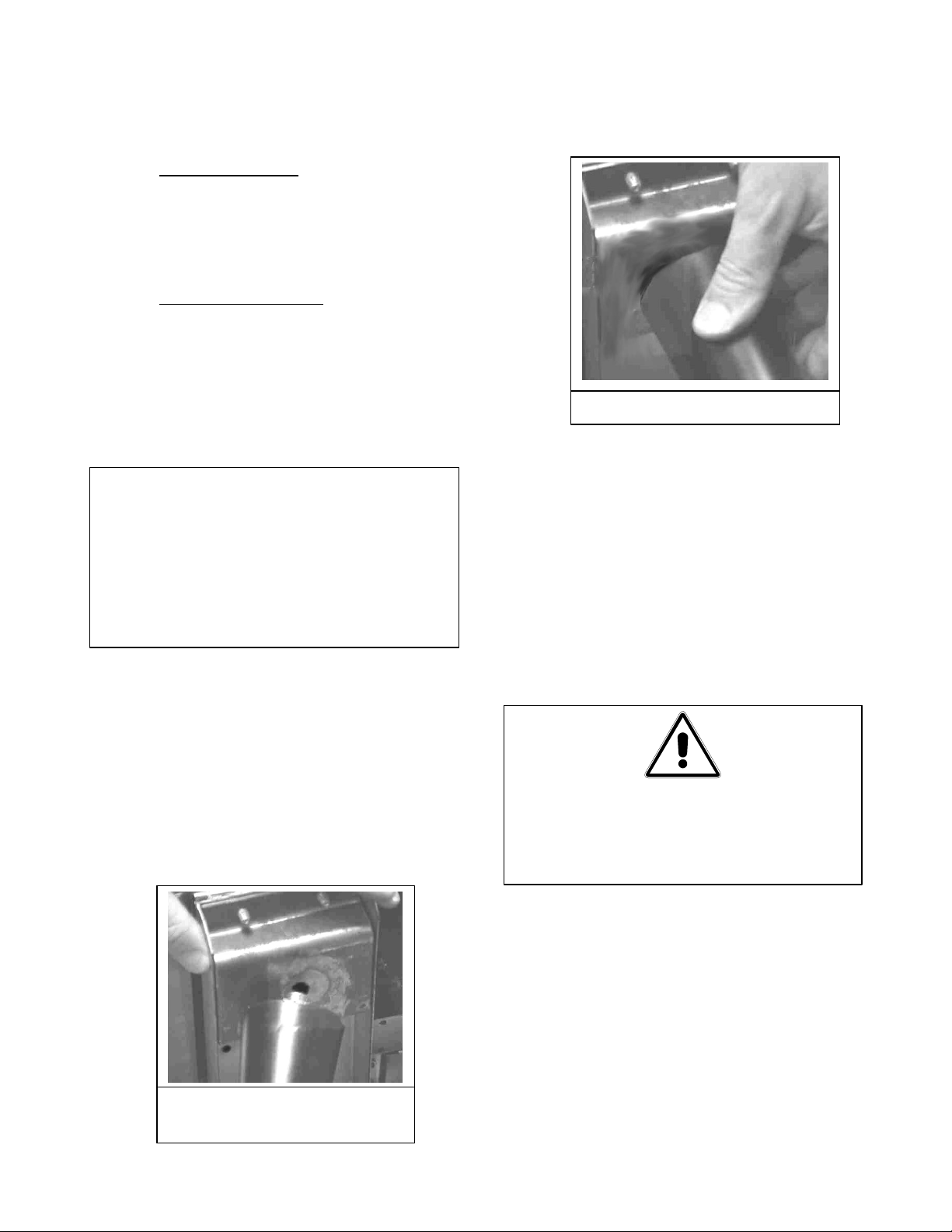
c. Insert the threaded leg screw into leg
support coupling.
d. Turn the leg clockwise until the leg is
hand tight against the leg support
assembly.
e. Then lower gently to prevent undue
strain to the legs and internal mounting
hardware. Using a pallet or lift jack to
lift rather than tilting is recommended.
3.2 LEGS:
a. Install legs (or optional fixed casters)
near where the fryer is to be used, as
neither is secure for long transit. Unit
can be curb mounted or equipped with
the legs or casters provided.
b. After unpacking, use a pallet or lift
jack to raise the fryer about a foot
before installing the legs.
INSTALLING LEG INTO
LEG SUPPORT ASSEMBLY
f. Proceed to 3.4 Leveling and follow
instructions to ensure the fryer is level
before using.
WARNING
DO NOT INSTALL SWIVEL CASTERS
ON THIS FRYER. THE FRYER MAY TIP
3.3 CASTERS:
a. If casters are desired, install fixed-type
casters only on the rear of this fryer.
b. Install fixed-type casters near where
the fryer is to be used, as casters are
not secure for long transit. Unit can
be curb mounted or equipped with
either the legs or casters provided.
After unpacking, use a pallet or lift
5
Page 7
jack to raise the unit about a foot
NOT LEVEL, THE FRYER MAY TIP
before installing the casters.
c. Position the caster assembly against
the leg support assembly. Align the
holes in the caster assembly plate
with the corresponding holes in the
leg support assembly on the fryer.
Insert the threaded caster bolts
through the caster assembly plate into
the leg support assembly. Hand
tighten each bolt the base of the caster
and tighten the caster by hand, turning
clockwise, until it is snug against the
leg support assembly.
d. Tighten the fixed caster assembly
against the leg support assembly by
using an adjustable crescent wrench.
e. Rear rigid casters are not adjustable.
The floor where the fryers are installed
must be level.
WARNING!
corner and measure with the
spirit level. The legs have about
one inch of adjustment thread.
2. Adjust leg height with an
adjustable or 1-1/16” open end
wrench.
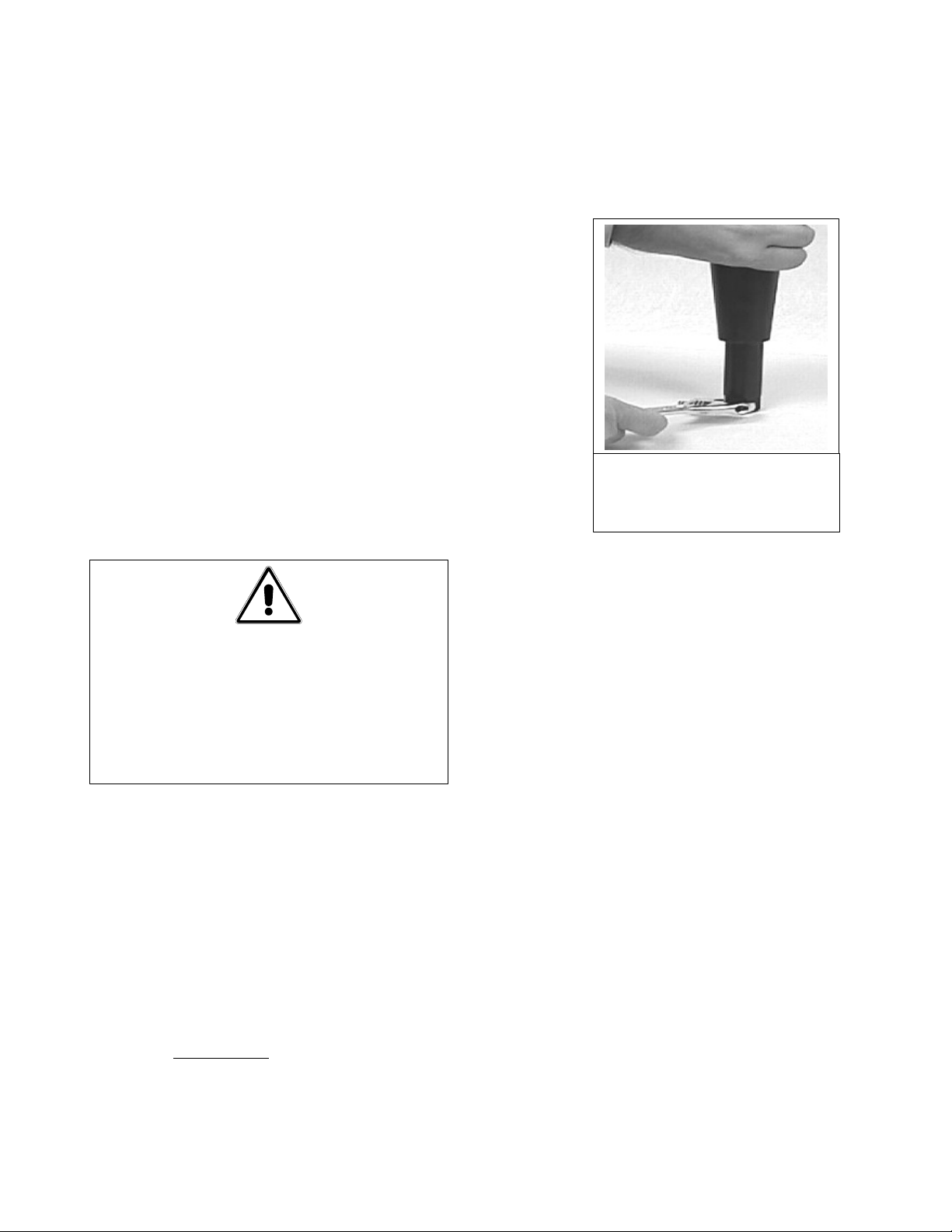
ADJUST LEG HEIGHT
WITH AN ADJUSTABLE
WRENCH
3. When leveling the unit, the leg
body should be held firmly to
keep the leg from rotating while
turning the hex bullet foot to the
required height.
A FRYER MUST BE LEVEL BEFORE
FILLING WITH OIL. IF THE FRYER IS
OVER AND MAY CAUSE INJURY TO
THE OPERATOR.
3.4 LEVELING:
a. Place a carpenter’s spirit level across
the top of the fryer and level the unit
both front-to-back and side-to-side.
If it is not level, the unit may not
function efficiently, the oil may not
drain properly for filtering and in a
line-up it may not match adjacent
units.
b. Legs (Only):
1. If the floor is smooth and level,
level the unit by using the leg
screw threads; adjust to the high
c. If the floor is uneven or has a
decided slope, a smooth platform is
recommended for placing the unit on
and not relying on leg/caster thread
adjustment.
d. If the fryer is moved, re-level the
fryer following the instructions
given in Section 3.4.
e. This fryer must be restrained to
prevent tipping when installed in
order to avoid the splashing of hot
liquid. The means of restraint may
be the manner of installation, such as
connection to a battery of appliances
or installing the fryer in an alcove, or
by separate means, such as adequate
ties. A bracket has been provided on
the fryer back panel for this purpose.
6
Page 8
The install must be reviewed at the
time of installation to ensure it
meets the intent of these
instructions. The on-site supervisor
and/or operator(s) should be made
aware there is a restraint on the
appliance and, if disconnection of
the restraint is necessary, to
reconnect this restraint after the
appliance has been returned to its
originally installed position.
3.5 ELECTRICAL CONNECTIONS:
Plan and carry out installation in
accordance with local codes.
a. Connections: Connections to the
terminal block and grounding lug
should be made through the hole
provided for this purpose in the
junction box.
thermostat calibration, and cleans the
vessel for initial food production.
1. Fill the fryer vessel with hot or
cold water to the oil level line
scribed in the back of the tank.
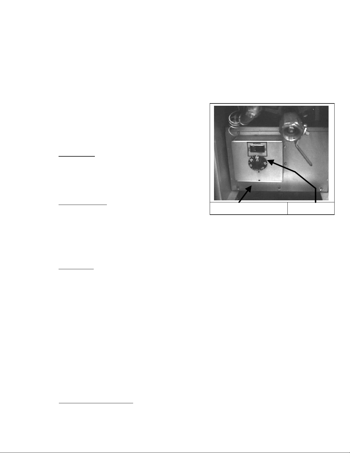
2. Set the thermostat/temperature
controller dial to 220°F, just above
that of boiling water.
b. Wiring Diagram: It is attached to the
inside of the fryer door. Amperage for
each unit depends on the type of
installation and accessories supplied
with the unit.
3.6 INITIAL START-UP:
a. CLEANING: New units are wiped
clean with solvents at the factory to
remove any visible signs of dirt, oil,
grease, etc. remaining from the
manufacturing process, then coated
lightly with oil. Wash thoroughly with
hot, soapy water to remove any film
residue and dust or debris before food
preparation, then rinse out and wipe
dry. Wash also any accessories
shipped with the unit. Close the drain
valve completely and remove the
crumb screen. Make sure the screws
holding the thermostat and limit
control sensing bulbs into the vessel
are tight.
b. HEATING THE VESSEL: This step
checks heater element operation, initial
Temperature Controller
3. Toggle the power switch “ON”.
The heater elements will begin
heating.
4. When the water starts to boil, turn
the dial to below 210°F. The
elements will turn off and the
water will stop boiling.
5. When satisfied that the heaters and
thermostat operate properly, drain
the vessel of water and dry
thoroughly. Refill fry vessel with
shortening as directed in section
3.7, Final Preparation.
3.7 FINAL PREPARATION:
a. When using liquid shortening (cooking
oil), fill the fryer to the “oil level” line
scribed into the back of the fryer
vessel.
b. When using solid shortening, either
melt it first, or cut into small pieces
Power Switch
7
Page 9
and pack into cool zone (bottom) of
NEVER OPERATE FRYER WITHOUT
the frying vessel. Be careful to not
leave any air spaces or disturb the
sensing bulbs. Melt shortening by
turning the heaters “ON” for about
five or ten seconds, “OFF” for a
minute, repeating cycle until
shortening is melted. If oil starts to
smoke while melting this way, shorten
the “ON” cycle and lengthen the
“OFF” cycle. Smoke shows that you
are scorching the shortening and
cutting its useful life.
NOTE: NEVER MELT A SOLID BLOCK
OF SHORTENING BY SETTING IT IN
THE VESSEL. THIS IS UNSAFE,
INEFFICIENT AND DANGEROUS.
c. When the fryer vessel is filled and the
shortening melted, replace the crumb
screen over the heater elements.
d. Before starting operation, turn the
temperature controller to the probable
working temperature; wait for the
temperature to stabilize then check
with a high-quality immersion
thermometer.
WARNINGS
ENOUGH COOKING COMPOUND OR
WATER IN THE VESSEL TO COVER
THE HEATING ELEMENTS.
ALWAYS WEAR OIL-PROOF,
INSULATED GLOVES WHEN
WORKING WITH THE FRYER FILLED
WITH HOT OIL.
ALWAYS DRAIN HOT OIL INTO A
METAL CONTAINER. HOT OIL CAN
MELT PLASTIC BUCKETS AND CRACK
GLASS CONTAINERS.
8
Page 10
NOZZLE DOWN INTO THE FRY
4. DAILY OPERATION
4.1 OPENING: At opening time, always
visually check that the power switch and the
thermostat are “OFF”.
CAUTION
IF ELECTRICAL POWER SERVICE IS
DISRUPTED FOR MORE THAN A FEW
SECONDS, TURN FRYER OFF. THIS
WILL PREVENT THE FRYER FROM
ACCIDENTALLY HEATING OIL WHEN
POWER SERVICE IS RESUMED.
4.2 GENERAL USE:
a. For consistent quality product,
convenience and long-term savings, use
a high-quality liquid frying compound.
WARNING
IF USING SOLID SHORTENING, NEVER
MELT A BLOCK OF SHORTENING BY
SETTING IT WHOLE IN THE FRYER
VESSEL. THIS IS DANGEROUS AND CAN
EASILY CAUSE THE SHORTENING TO
OVERHEAT, SCORCH, DAMAGE THE
rest in the vessel by turning power
switch off and on.
b. Turn the power switch on; set
temperature controller to 350°F (177°C).
In less than 30 minutes, the frying
compound temperature will stabilize and
be ready for production.
4.4 FILTERING:
a. Filter the frying compound at least once
daily or more frequently if cooking is
heavy. Prior to filtering, align the filter
unit with the drain valve. Attach the
drain valve extension to ensure frying
compound flows into the filter unit safely.
b. Filtering the frying compound assures a
better taste to the food being prepared,
minimizes flavors being transferred from
batch to batch, and increases frying
compound lifespan.
c. If using solid shortening, clear return
lines before turning off the filter motor
and hang any flexible lines up to drain.
As it cools, solid shortening solidifies and
clogs lines.
b. Although a temperature of 350°F
(177°C) is recommended for most
cooking operations, set the fryer at the
lowest possible temperature which
produces a high quality end product
while ensuring maximum life of frying
compound.
When the fryer is not in use, the
thermostat should be set lower than that
used during cooking.
4.3 TURN ON PROCEDURES:
a. If fryer is empty, pour enough frying
compound into the vessel to fill the
vessel to the "oil level” line scribed on
the rear wall. If solid shortening is to be
used, melt enough in a separate
container to cover the heating elements
in the bottom of the vessel, then melt the
CAUTION
WHEN FILTERING, NEVER LEAVE THE
FILTER UNATTENDED. ALWAYS POINT
THE FLEXIBLE OIL RETURN HOSE
VESSEL
TO PREVENT THE SPRAYING OF HOT OIL
4.5 CLOSING: When closing at night, filter
oil in all fryers and drain the filter lines.
Cover the open tanks of oil. Turn power
switch “OFF”.
4.6 SHUTDOWN: When shutting down for
periods longer than overnight, drain the
frying compound and clean the vessel
thoroughly. Either discard the frying
compound or return it filtered to the vessel
and then cover it. Turn both the power switch
and temperature controller “OFF”.
9
Page 11
5. CLEANING & MAINTENANCE
WARNING
IF FRYER IS NOT COMPLETELY EMPTY
OF OIL, ADJUSTMENT, ALTERATION,
SERVICE OR MAINTENANCE CAN CAUSE
PROPERTY DAMAGE AND PERSONAL
INJURY.
5.4 WEEKLY:
To return the unit to its previous installed
position see sections 3.4 and 5.3 of this
manual.
a. Completely drain the oil from the fry
vessel into either the filter or a steel
container. Do not use a plastic bucket
or glass container.
5.1 GENERAL: Any piece of equipment
works better and lasts longer when
maintained properly and kept clean.
Cooking equipment is no exception. The
fryer must be kept clean during the
working day and thoroughly cleaned at the
end of each day.
5.2 DAILY: Wash all removable parts.
Clean all exterior surfaces of the body. Do
not use cleansers, steel wool, or any other
abrasive material on the stainless steel.
Filter the cooking oil and replace if
necessary. The oil should be filtered more
often than daily under heavy use
conditions.
5.3 ACCESS FOR SERVICING:
The appliance is equipped with a bracket
attached on the center of the structural
back to connect a restraining device
supplied by the installer. The restraining
device should meet the requirements
specified in section 3.4.e of this manual.
In addition, if the fryers installed have
casters provided by Dean Industries, both
rear casters come with a locking
mechanism that prevents the fryer from
moving when the lever or each mechanism
is turned “ON”.
To gain access for servicing, the
restraining device has to be removed from
the bracket and both front casters locking
mechanisms have to be turned “OFF”.
b. Clean the vessel with a good grade of
cleaner or hot water and a strong
detergent.
c. Close the drain valve and refill with
either the cleaning solution or water
and detergent.
d. Set operating thermostat to 220° F
(104°C). Bring to a rolling boil, then
turn the heat down and let the mixture
stand until deposits and/or carbon
spots can be rubbed off with the
Teflon brush.
e. Scrub tank walls, bottom and heating
tubes. Then drain vessel and rinse in
clear water.
DO NOT DRAIN WATER INTO
FILTER. WATER WILL
DAMAGE THE FILTER PUMP.
f. Refill with clear water, set operating
thermostat to 220°F (104°C), and boil
again. Once boiling is completed, turn
operating thermostat “OFF”, drain,
rinse, and dry thoroughly.
CAUTION
DO NOT LET WATER BOIL DOWN TO THE
POINT THAT ELEMENTS ARE EXPOSED
AS THIS WILL DAMAGE THEM.
g. Immediately refill with cooking oil or
frying compound as directed in
Section 4.3.
10
Page 12
WARNING
DO NOT LET WATER SPLASH INTO THE
TANK OF HOT OIL. IT WILL SPLATTER
AND CAN CAUSE SEVERE BURNS.
5.5 PERIODIC: The fryer should be
checked and adjusted periodically by
qualified service personnel as part of a
regular kitchen maintenance program.
5.6 STAINLESS STEEL: All stainless
steel fryer body parts should be wiped
regularly with hot, soapy water during the
day and with a liquid cleaner designed for
this material at the end of each day.
a. Do not use steel wool, abrasive cloths,
cleansers or powders!
b. Do not use a metal knife, spatula or any
other metal tool to scrape stainless
steel! Scratches are almost impossible
to remove.
c. If it is necessary to scrape the stainless
steel to remove any encrusted
materials, soak the area first to loosen
the material, then use a wood or nylon
scraper only.
11
Page 13
6. TROUBLESHOOTING GUIDE
These troubleshooting procedures must be carried out only be a Factory Authorized Service Center or a
local service company specializing in hotel and restaurant cooking appliances. The problems and
possible solutions given below cover those most commonly encountered.
FOR DETAILED TROUBLESHOOTING AND SERVICE-RELATED INFORMATION, CALL
THE DEAN SERVICE HOTLINE AT 1-800-551-8633.
PROBLEM CORRECTIVE ACTION
Operator hears click sound
when the temperature
controller dial is turned but
vessel remains cold. No
evidence that elements are
warming the vessel.
Poor temperature control on
the cold side; excessive
warm-up time; temperature
recovery is slow or
inadequate when vessel is
loaded; or uneven heating.
Poor temperature control on
the hot side; excessive
temperature overshooting
during warm-up; scorching;
overheating; or high limit
switch must be reset often.
With the power switch “ON”:
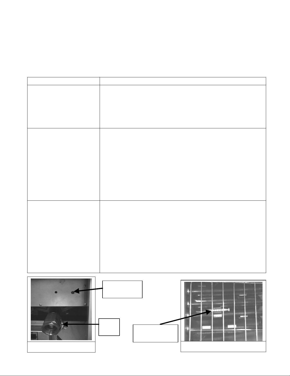
1. Manually reset the high temperature limit switch (push red button
on the panel above the drain valve). See Figure 6-1.
2. Check branch or main circuit breakers or fuses are not tripped or
blown.
Check thermostat adjustment:
1. Check that the thermostat bulb/probe in the vessel has not been
knocked loose from its operating position. It should be clamped to
the 2nd element with 1/16 inch spacing. See Figure 6-2.
2. Place the sensing bulb of a high quality immersion thermometer
about 1-1/2 inches above the thermostat sensing bulb and set the
temperature controller dial to 350°F.
3. Wait at least 30 minutes for the oil temperature to stabilize.
4. If temperature is not within +/- 10°F of the dial setting, call
service for a new operating thermostat/temperature controller.
Check thermostat adjustment:
1. Check that the thermostat bulb/probe in the vessel has not been
knocked loose from its operating position. It should be clamped to
the 2nd element with 1/16 inch spacing.
2. Place the sensing bulb of a high quality immersion thermometer
about 1-1/2 inches above the thermostat sensing bulb and set the
temperature controller dial to 350°F.
3. Wait at least 30 minutes for the oil temperature to stabilize.
4. If temperature is not within +/- 10°F of the dial setting, call
service for a new operating thermostat/temperature controller.
Figure 6-1
High Limit
Reset Switch
Drain
Valve
Sensing Bulb in
Fryer Vessel
Figure 6-2
12
Page 14
7. COMPONENT LISTING AND INSTALLATIONSTANDARDS
The following is a selection of listing and installation standards applicable to non-cooking
components often supplied as part of food service equipment. The selection is not intended to be
complete and other nationally recognized standards may be appropriate. This listing was current as
of the revision date shown on the cover of this manual.
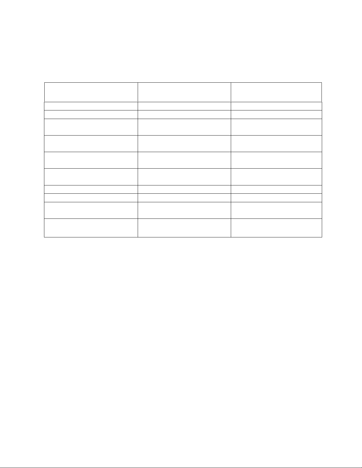
LISTING
COMPONENT
Grease Extractor ANSI/UL 710-1990 ANSI/NFPA 96-1991
Power Ventilators ANSI/UL 705-1984 ANSI/NFPA 96-1987
Filter Unit
Fire Ext. (CO2)
Fire Ext. (Dry Chemical)
Fire Ext. (Water)
Fire Ext. (Foam) ANSI/NFPA 11-1988
Automatic Sprinklers ANSI/UL 199-1990 ANSI/MFPA 13-1989
Smoke Detectors
Heat Detectors for Fire
Protective Signaling Devices
STANDARD
ANSI/UL 900-1987
ANSI/UL 586-1990
ANSI/UL 154-1990
CAN/ULC-S503-M90
ANSI/UL 299-1990
CAN/ULC-S504-M89
ANSI/US 626-1990
CAN4-S507-M83
ANSI/UL 521-1988
CAN/ULC-S530-1978
ANSI/UL 521-1988
ULC-S530-1978
INSTALLATION
STANDARD
ANSI/NFPA 96-1987
ANSI/NFPA 96-1987
ANSI/NFPA 12-1989
ANSI/NFPA 17-1990
ANSI/MFPA 13-1989
ANSI/NFPA 72B-1986
ANSI/NFPA 72B-1986
13
Page 15
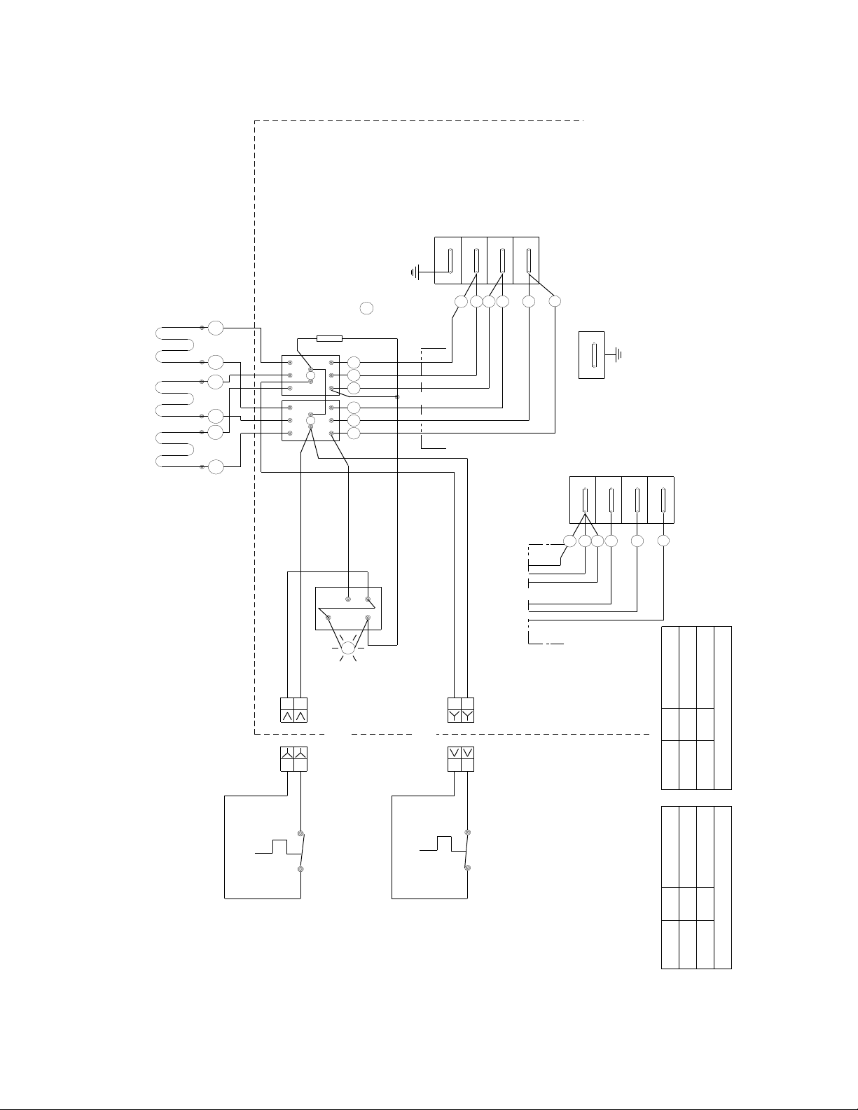
8. WIRING DIAGRAM
P/N 1368
K1=240/208V COIL
K2
CONTACTORS
5 AMP
FOR FIRE SAFETY SHUT OFF
CONNECT TO SWITCH AT
EXTINGUISHER HEAD
E
FUSE
P/N 1693
THREE
PHASE
N
L3
4,6
4
6
L1
L2
1,3
2,5
5
2
3
TERMINAL
BLOCK
1
5 6
4
3
2
HEATING ELEMENTS
1
K2
K1
1
1
PURP
2
2
BLK
BLUE
2 PIN AMP
SOCKET PLUG
GROUND
TERMINAL
5 2 4 6
1 3
PHASE
THREE
WHT
SPST
P/N 2025
POWER SWITCH
BLK
SOCKETPLUG
2
PURP
1
N
L3
542
6
L1
L2
1
3
14-0592-8
ASSEMBLY
CONTACTOR BOX
BLOCK
TERMINAL
ELEMENT NO
KW
4 WIRE 3 PHASE
1
2
2 PIN AMP
220
VOLTAGE
HEATER WIREWAY ASSEMBLY
RED
NC
C
HIGH LIMIT
P/N 2672
P/N 1365 or
THERMOSTAT
14
P/N 2557
THERMOSTAT
14-0592-812.0220 12.0
3 WIRE 3 PHASE
208 14.0 14-0592-6
VOLTAGE KW ELEMENT NO
Page 16

Dean, 8700 Line Avenue, Shreveport, Louisiana 71135
TEL 1-318-865-1711 FAX (Parts) 1-318-219-7140 (Tech Support) 1-318-219-7135
PRINTED IN THE UNITED STATES
SERVICE HOTLINE
1-800-551-8633
Price: $6.00
819-5646 09-98
 Loading...