

Page 1
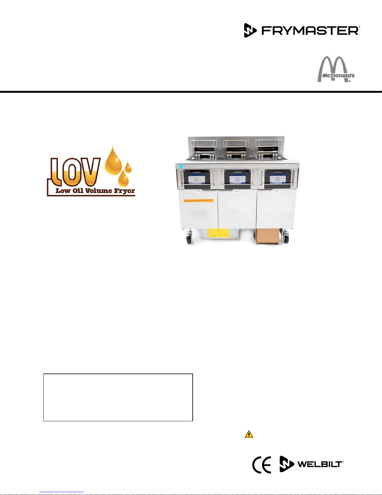
BIELA14-T Series
y
Gen III LOV™ Electric Fryer
Installation, Operation and Maintenance Manual
This manual is updated as new information and models are released. Visit our website for the latest manual.
This equipment chapter is to be installed in the Fryer Section of the Equipment Manual.
TABLE OF CONTENTS
WARNINGS AND NOTICES ............................................................................................................... Page ii
WARRANTY STATEMENT .................................................................................................................. Page v
INTRODUCTION ................................................................................................................................ Page 1-1
INSTALLATION INSTRUCTIONS ...................................................................................................... Page 2-1
OPERATING INSTRUCTIONS ............................................................................................................ Page 3-1
M4000 COMPUTER INSTRUCTIONS ............................................................................................... Page 4-1
OPERATING THE BUILT-IN FILTRATION SYSTEM .......................................................................... Page 5-1
PREVENTIVE MAINTENANCE ........................................................................................................... Page 6-1
OPERATOR TROUBLESHOOTING ................................................................................................... Page 7-1
RTI (BULK OIL) INSTRUCTIONS ....................................................................................................... Page A-1
JIB PREPARATION WITH SOLID SHORTENING OPTION ............................................................... Page B-1
SOLID SHORTENING MELTING UNIT USE ...................................................................................... Page C-1
FOR YOUR SAFETY
Do Not Store or use gasoline or other
flammable vapors and liquids in the vicinity
of this or an
other appliance.
CAUTION
*8197340*
READTHEINSTRUCTIONSCAREFULLYBEFOREUSING
Part Number: FRY_IOM_8197340 10/2018
OriginalInstructions
Page 2
NOTICE
IF, DURING THE WARRANTY PERIOD, THE CUSTOMER USES A PART FOR THIS FRYMASTER FOOD SERVICE
EQUIPMENT OTHER THAN AN UNMODIFIED NEW OR RECYCLED PART PURCHASED DIRECTLY FROM FRYMASTER,
OR ANY OF ITS FACTORY AUTHORIZED SERVICERS, AND/OR THE PART BEING USED IS MODIFIED FROM ITS
ORIGINAL CONFIGURATION, THIS WARRANTY WILL BE VOID. FURTHER, FRYMASTER DEAN AND ITS AFFILIATES
WILL NOT BE LIABLE FOR ANY CLAIMS, DAMAGES OR EXPENSES INCURRED BY THE CUSTOMER WHICH ARISE
DIRECTLY OR INDIRECTLY, IN WHOLE OR IN PART, DUE TO THE INSTALLATION OF ANY MODIFIED PART AND/OR
PART RECEIVED FROM AN UNAUTHORIZED SERVICER.
NOTICE
This appliance is intended for professional use only and is to be operated by qualified personnel only. A
Frymaster Authorized Servicer (FAS) or other qualified professional should perform installation, maintenance,
and repairs. Installation, maintenance, or repairs by unqualified personnel may void the manufacturer’s
warranty. See Chapter 1 of this manual for definitions of qualified personnel.
NOTICE
This equipment must be installed in accordance with the appropriate national and local codes of the country
and/or region in which the appliance is installed. See NATIONAL CODE REQUIREMENTS in Chapter 2 of this
manual for specifics.
NOTICE TO U.S. CUSTOMERS
This equipment is to be installed in compliance with the basic plumbing code of the Building Officials and Code
Administrators International, Inc. (BOCA) and the Food Service Sanitation Manual of the U.S. Food and Drug
Administration.
NOTICE
This appliance is intended to be used for commercial applications, for example in kitchens of restaurants,
canteens, hospitals and in commercial enterprises such as bakeries, butcheries, etc., but not for continuous
mass production of food.
NOTICE
Drawings and photos used in this manual are intended to illustrate operational, cleaning and technical
procedures and may not conform to onsite management operational procedures.
NOTICE TO OWNERS OF UNITS EQUIPPED WITH TOUCH SCREEN CONTROLLERS
U.S.
This device complies with Part 15 of the FCC rules. Operation is subject to the following two conditions: 1) This
device may not cause harmful interference, and 2) This device must accept any interference received, including
interference that may cause undesired operation. While this device is a verified Class A device, it has been
shown to meet the Class B limits.
CANADA
This digital apparatus does not exceed the Class A or B limits for radio noise emissions as set out by the ICES-003
standard of the Canadian Department of Communications.
Cet appareil numerique n’emet pas de bruits radioelectriques depassany les limites de classe A et B prescrites
dans la norme NMB-003 edictee par le Ministre des Communcations du Canada.
DANGER
When installed, this appliance must be electrically grounded in accordance with local codes, or in the absence of
local codes, with the National Electrical Code, ANSI/NFPA 70, the Canadian Electrical Code, CSA C22.2, or the
appropriate national code of the country in which installed.
ii
Page 3

WARNING
The appliance must be installed and used in such a way that any water cannot contact the fat or oil.
DANGER
Improper installation, adjustment, maintenance or service, and unauthorized alterations or modifications can
cause property damage, injury, or death. Read the installation, operating, and service instructions thoroughly
before installing or servicing this equipment.
DANGER
The front ledge of this appliance is not a step! Do not stand on the appliance. Serious injury can result from
slips or contact with the hot oil.
FOR YOUR SAFETY
Do not store or use gasoline or other flammable liquids or vapors in the vicinity of this or any other appliance.
DANGER
The crumb tray in fryers equipped with a filter system must be emptied into a fireproof container at the end of
frying operations each day. Some food particles can spontaneously combust if left soaking in certain shortening
material.
WARNING
Do not bang fry baskets or other utensils on the fryer’s joiner strip. The strip is present to seal the joint
between the fry vessels. Banging fry baskets on the strip to dislodge shortening will distort the strip, adversely
affecting its fit. It is designed for a tight fit and should only be removed for cleaning.
DANGER
Adequate means must be provided to limit the movement of this appliance without depending on or
transmitting stress to the electrical conduit. A restraint kit is provided with the fryer. If the restraint kit is
missing contact your local KES.
DANGER
This fryer has a power cord (three-phase) for each frypot and may have a single five-wire cord for the entire
system. Prior to movement, testing, maintenance and any repair on your Frymaster fryer; disconnect ALL
electrical power cords from the electrical power supply.
Keep all items out of drains. Closing actuators may cause damage or injury.
This appliance is not intended for use by children under the age of 16 or persons with reduced physical, sensory
or mental capabilities, or lack of experience and knowledge, unless they have been given supervision
concerning use of the appliance by a person responsible for their safety. Do not allow children to play with this
appliance.
To ensure the safe and efficient operation of the fryer and hood, the electrical plug for the 120-volt line, which
powers the hood, must be fully engaged and locked in its pin and sleeve socket.
The instructions in this manual for using a bulk oil system for filling and discarding oil are for an RTI system.
These instructions may not be applicable to other bulk oil systems.
DANGER
WARNING
WARNING
NOTICE
iii
Page 4
DANGER
This appliance must be connected to a power supply having the same voltage and phase as specified on the
rating plate located on the inside of the appliance door.
WARNING
Use caution and wear appropriate safety equipment to avoid contact with hot oil or surfaces that may cause
severe burns or injury.
DANGER
Do not spray aerosols in the vicinity of this appliance while it is in operation.
DANGER
No structural material on the fryer should be altered or removed to accommodate placement of the fryer under
a hood. Questions? Call the Frymaster Dean Service Hotline at 1-800-551-8633.
WARNING
Do not block the area around the base or under the fryers.
WARNING
Do not use water jets to clean this equipment.
WARNING
Operation, installation, and servicing of this product may expose you to chemicals/products including
[Bisphenol A (BPA), glass wool or ceramic fibers, and crystalline silica], which is [are] known to the State of
California to cause cancer, birth defects or other reproductive harm. For more information go to
www.P65Warnings.ca.gov.
iv
Page 5

LOV-T™ ELECTRIC WARRANTY STATEMENT
Frymaster, L.L.C. makes the following limited warranties to the original purchaser only for this
equipment and replacement parts:
A. WARRANTY PROVISIONS - FRYERS
1. Frymaster L.L.C. warrants all components against defects in material and workmanship
for a period of two years.
2. All parts, with the exception of the frypot, O-rings and fuses, are warranted for two
years after installation date of fryer.
3. If any parts, except fuses and filter O-rings, become defective during the first two years
after installation date, Frymaster will also pay straight-time labor costs up to two hours
to replace the part, plus up to 100 miles/160 km of travel (50 miles/80 km each way).
B. WARRANTY PROVISIONS - FRYPOTS
The frypot has a lifetime parts and labor warranty. If a frypot develops a leak after
installation, Frymaster will replace the frypot, allowing up to the maximum time per the
Frymaster time allowance chart hours of straight-time labor. Components attached to the
frypot, such as the high-limit, probe, gaskets, seals, and related fasteners, are also covered
by the lifetime warranty if replacement is necessitated by the frypot replacement. Leaks
due to abuse or from threaded fittings such as probes, sensors, high-limits, drain valves or
return piping are not included.
C. WARRANTY PROVISIONS – EASY TOUCH – TOUCH SCREEN CONTROLLER
Frymaster L.L.C. warrants the Easy Touch - Touch Screen Controllers against defective material or
workmanship for a period of three years parts and labor from the original installation date.
D. PARTS RETURN
All defective in-warranty parts must be returned to a Frymaster Authorized Servicer within
60 days for credit. After 60 days, no credit will be allowed.
E. WARRANTY EXCLUSIONS
This warranty does not cover equipment that has been damaged due to misuse, abuse,
alteration, or accident such as:
improper or unauthorized repair (including any frypot which is welded in the field);
failure to follow proper installation instructions and/or scheduled maintenance procedures
as prescribed in your MRC cards. Proof of scheduled maintenance is required to maintain
the warranty;
improper maintenance;
v
Page 6

damage in shipment;
abnormal use;
removal, alteration, or obliteration of either the rating plate or the date code on the
heating elements;
operating the frypot without shortening or other liquid in the frypot;
no fryer will be warranted for which a proper start-up form has not been received.
This warranty also does not cover:
transportation or travel over 100 miles/160 km (50 miles/80 km each way), or travel over
two hours;
overtime or holiday charges;
consequential damages (the cost of repairing or replacing other property which is
damaged), loss of time, profits, use or any other incidental damages of any kind.
There are no implied warranties of merchantability or fitness for any particular use or purpose.
This warranty is applicable at the time of this printing and is subject to change.
vi
Page 7
BIELA14-T SERIES GEN III LOV™ ELECTRIC FRYER
CHAPTER 1: INTRODUCTION
NOTE: The Frymaster BIELA14-T fryer requires a start-up, demonstration and training before
normal restaurant operations can begin.
1.1 General
Read the instructions in this manual thoroughly before attempting to operate this equipment. This manual covers
all configurations of McDonald’s BIELA14-T LOV™ models. The fryers in this model family have most parts in
common, and when discussed as a group, will be referred to as “LOV™ fryers.
The BIELA14-T LOV™ fryers feature a low oil volume frypot, automatic oil top off, automatic intermittent filtration
unit and a touch screen. The Euro-Look design incorporates a rounded topcap and a large round drain, which
ensures that fries and other debris, will be washed into the filter pan. The BIELA14-T LOV™ fryers are controlled
with an M4000 touch screen controller. Fryers in this series come in full- or split-vat arrangements, and can be
purchased in batteries of up to five vats.
Each frypot is equipped with a temperature probe for precise temperature control.
BIELA14-T LOV™ fryers are shipped completely assembled. All fryers are shipped with a package of standard
accessories. Each fryer is adjusted, tested, and inspected at the factory before crating for shipment.
1.2 Safety Information
Before attempting to operate your unit, read the instructions in this manual thoroughly.
Throughout this manual, you will find notations enclosed in double-bordered boxes similar to the one below.
CAUTION
CAUTION boxes contain information about actions or conditions that may cause or result in a
malfunction of your system.
WARNING
WARNING boxes contain information about actions or conditions that may cause or result in damage
to your system, and which may cause your system to malfunction.
DANGER
DANGER boxes contain information about actions or conditions that may cause or result in injury to
personnel, and which may cause damage to your system and/or cause your system to malfunction.
he BIELA14-T LOV™ fryers incorporate a high-temperature detection feature which shuts off power to the
T
elements should the temperature controls fail.
The controller is equipped with a lithium battery. Replace battery with Panasonic CR2032 3V lithium battery, part
number 8074674 only. Use of another battery may present a risk of fire or explosion. The battery can be
purchased from your Factory Authorized Servicer.
CAUTION
Battery may explode if mistreated. Do not recharge, disassemble or dispose of in fire.
1-1
Page 8
1.3 Information for the M4000 Controllers
This equipment has been tested and found to comply with the limits for a Class A digital device, pursuant to Part 15
of the FCC rules. While this device is a verified Class A device, it has been shown to meet the Class B limits. These
limits are designed to provide reasonable protection against harmful interference when the equipment is operated
in a commercial environment. This equipment generates, uses and can radiate radio frequency energy and, if not
installed and used in accordance with the instruction manual, may cause harmful interference to radio
communications. Operation of the equipment in a residential area is likely to cause harmful interference in which
case the user will be required to correct the interference at their own expense.
The user is cautioned that any changes or modifications not expressly approved by the party responsible for
compliance could void the user's authority to operate the equipment.
If necessary, the user should consult the dealer or an experienced radio and television technician for additional
suggestions.
The user may find the following booklet prepared by the Federal Communications Commission helpful: "How to
Identify and Resolve Radio-TV Interference Problems". This booklet is available from the U.S. Government Printing
Office, Washington, DC 20402, Stock No. 004-000-00345-4.
1.4 European Community (CE) Specific Information
The European Community (CE) has established certain specific standards regarding equipment of this type.
Whenever a difference exists between CE and non-CE standards, the information or instructions concerned are
identified by means of shadowed boxes similar to the one below.
CE Standard
Example of box used to distinguish CE and
Non-CE specific information.
1.5 Installation, Operating, and Service Personnel
Operating information for Frymaster equipment has been prepared for use by qualified and/or authorized
personnel only, as defined in Section 1.6. All installation and service on Frymaster equipment must be
performed by qualified, certified, licensed, and/or authorized installation or service personnel, as defined in
Section 1.6.
1.6 Definitions
QUALIFIED AND/OR AUTHORIZED OPERATING PERSONNEL
Qualified/authorized operating personnel are those who have carefully read the information in this manual and
have familiarized themselves with the equipment functions, or who have had previous experience with the
operation of the equipment covered in this manual.
QUALIFIED INSTALLATION PERSONNEL
Qualified installation personnel are individuals, firms, corporations, and/or companies which, either in person or
through a representative, are engaged in and are responsible for the installation of electrical appliances. Qualified
personnel must be experienced in such work, be familiar with all electrical precautions involved, and have complied
with all requirements of applicable national and local codes.
1-2
Page 9

QUALIFIED SERVICE PERSONNEL
Qualified service personnel are those who are familiar with Frymaster equipment and who have been authorized by
Frymaster, L.L.C. to perform service on the equipment. All authorized service personnel are required to be
equipped with a complete set of service and parts manuals, and to stock a minimum amount of parts for Frymaster
equipment. A list of Frymaster Factory Authorized Servicers (FAS’s) is located on the Frymaster website at
www.frymaster.com. Failure to use qualified service personnel will void the Frymaster warranty on your
equipment
1.7 Shipping Damage Claim Procedure
What to do if your equipment arrives damaged:
Please note that this equipment was carefully inspected and packed by skilled personnel before leaving the factory.
The freight company assumes full responsibility for safe delivery upon acceptance of the equipment.
1. File Claim for Damages Immediately - regardless of extent of damage.
2. Inspect for and Record All Visible Loss or Damage, and ensure that this information is noted on the freight
bill or express receipt and is signed by the person making the delivery.
3. Concealed Loss or Damage- If damage is unnoticed until equipment is unpacked, notify the freight company
or carrier immediately upon discovery and file a concealed damage claim. This must be submitted within 15
days of date of delivery. Be sure to retain container for inspection.
Frymaster DOES NOT ASSUME RESPONSIBILITY FOR DAMAGE OR LOSS
INCURRED IN TRANSIT.
1.8 Service Information
For non-routine maintenance or repairs, or for service information, contact your local Frymaster Authorized Servicer
(FAS). In order to assist you quickly, the Frymaster Authorized Servicer (FAS) or Service Department representative
requires certain information about your equipment. Most of this information is printed on a data plate affixed to
the inside of the fryer door. Part numbers are found in the Service and Parts Manual. Parts orders may be placed
directly with your local FAS or distributor. A list of Frymaster Factory Authorized Servicers (FAS’s) is located on the
Frymaster website at www.frymaster.com. If you do not have access to this list, contact the Frymaster Service
Department at 1-800-551-8633 or 1-318-865-1711 or by email at [email protected].
The following information will be needed in order to assist you efficiently:
Model Number ______________________________________________
Serial Number _______________________________________________
Voltage ______________________________________________________
Nature of the Problem ______________________________________
______________________________________________________________
______________________________________________________________
RETAIN AND STORE THIS MANUAL IN A SAFE PLACE FOR FUTURE USE.
1-3
Page 10
BIELA14-T SERIES GEN III LOV™ ELECTRIC FRYER
CHAPTER 2: INSTALLATION INSTRUCTIONS
2.1 General Installation Requirements
Proper installation is essential for the safe, efficient, trouble-free operation of this appliance.
Qualified, licensed, and/or authorized installation or service personnel, as defined in Section 1.6 of this
manual, should perform all installation and service on Frymaster equipment.
Failure to use qualified, licensed, and/or authorized installation or service personnel (as defined in Section
1.6 of this manual) to install or otherwise service this equipment will void the Frymaster warranty and may
result in damage to the equipment or injury to personnel.
Where conflicts exist between instructions and information in this manual and local or national codes or
regulations, installation and operation shall comply with the codes or regulations in force in the country in
which the equipment is installed.
Service may be obtained by contacting your local Frymaster Authorized Servicer.
Building codes prohibit a fryer with its open tank of hot oil being installed beside an open flame of any type,
including those of broilers and ranges.
All fryers shipped without factory supplied cords and plug assemblies must be hardwired using flexible
conduit to the terminal block located on the rear of the fryer. These fryers should be wired to NEC
specifications. Hardwired units must include installation of restraint devices.
Adequate means must be provided to limit the movement of this appliance without depending on or
transmitting stress to the electrical conduit. A restraint kit is provided with the fryer. If the restraint kit is
missing contact your local Frymaster Authorized Servicer (FAS).
If this equipment is wired directly into the electrical power supply, a means for disconnection from the
supply having a contact separation of at least 3-mm in all poles must be incorporated in the fixed wiring.
This equipment must be positioned so that the plug is accessible unless other means for disconnection from
the power supply (e.g., a circuit breaker) is provided.
If this appliance is permanently connected to fixed wiring, it must be connected by means of copper wires
having a temperature rating of not less than 167°F (75°C).
If the electrical power supply cord is damaged, it must be replaced by a Frymaster Authorized Servicer or a
similarly qualified person in order to avoid a hazard.
DANGER
NOTICE
DANGER
NOTICE
NOTICE
NOTICE
NOTICE
This appliance must be connected to a power supply having the same voltage and phase as specified on the
rating plate located on the inside of the appliance door.
DANGER
2-1
Page 11
DANGER
All wiring connections for this appliance must be made in accordance with the wiring diagram(s) furnished
with the appliance. Refer to the wiring diagram(s) furnished with the appliance when installing or servicing
this equipment.
DANGER
Do not attach an apron drainboard to a single fryer. The fryer may become unstable, tip over, and cause
injury. The appliance area must be kept free and clear of combustible material at all times.
In the event of a power failure, the fryer(s) will automatically shut down. If this occurs, turn the power switch OFF.
Do not attempt to start the fryer(s) until power is restored.
This appliance must be kept free and clear of combustible material, except that it may be installed on combustible
floors.
2.1.1 Clearance and Ventilation
A clearance of 6 inches (15cm) must be provided at both sides and back adjacent to combustible construction. A
minimum of 24 inches (61cm) should be provided at the front of the equipment for servicing and proper operation.
WARNING
Do not block the area around the base or under the fryers.
DANGER
No structural material on the fryer should be altered or removed to accommodate placement of the fryer
under a hood. Questions? Call the Frymaster Dean Service Hotline at 1-800-551-8633.
2.1.2 Electrical Grounding Requirements
All electrically operated appliances must be grounded in accordance with all applicable national and local codes,
and, where applicable, CE codes. In the absence of local codes, the appliance must be grounded in accordance with
National Electrical Code, ANSI/NFPA 70, or the Canadian Electrical Code, CSA C22.2, as applicable. All units (cord
connected or permanently connected) should be connected to a grounded power supply
system. Wiring diagrams are supplied with the fryer. Refer to the rating plate on the inside of
the fryer door for proper voltages.
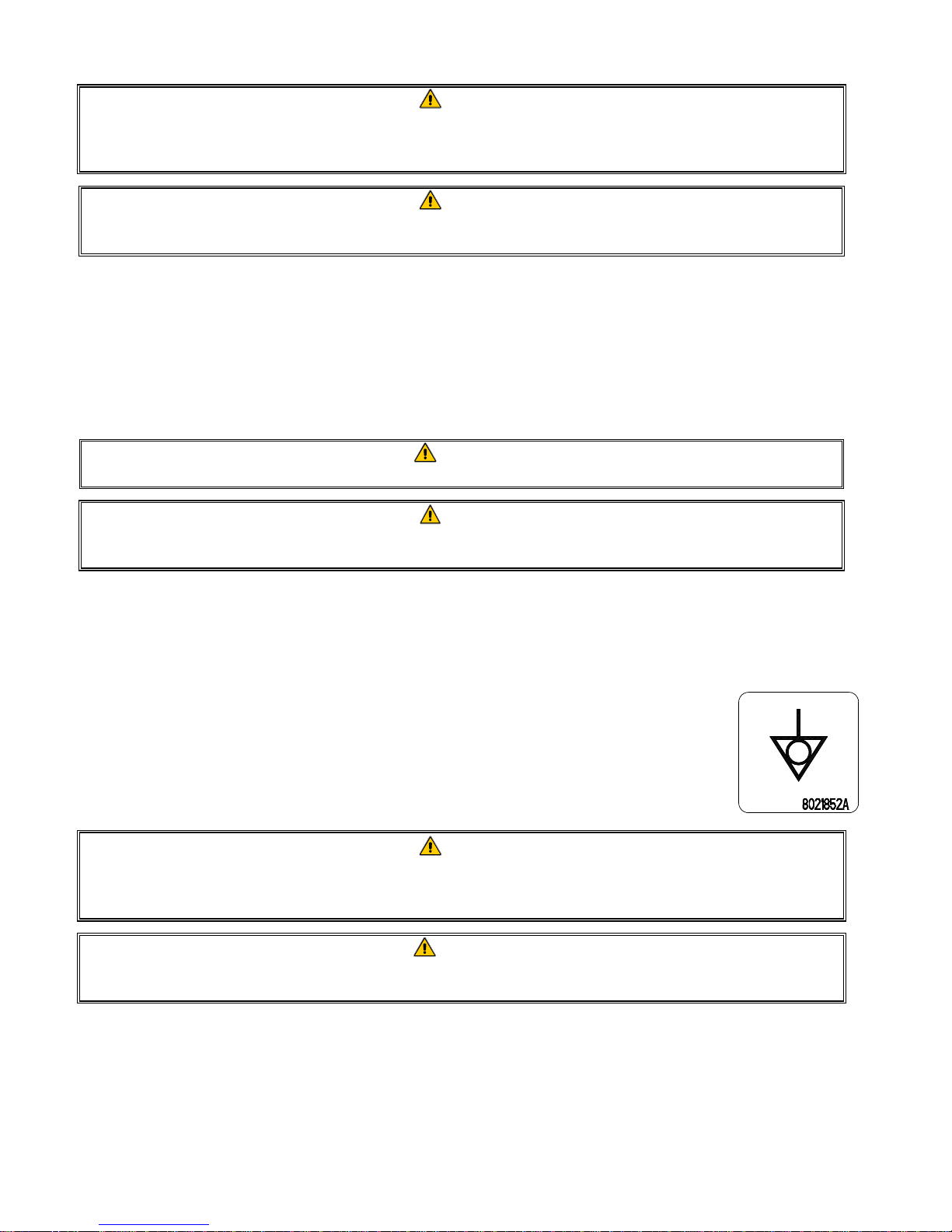
The equipotential grounding lug allows all the equipment in the same location to be electrically
connected to ensure there is no electrical potential difference between the units, which could be
hazardous.
This appliance is equipped with a special (grounding) plug for your protection against electrical shock, and
must be plugged directly into a properly grounded receptacle. Do not cut, remove, or otherwise bypass the
grounding prong on this plug!
To ensure the safe and efficient operation of the fryer and hood, the electrical plug for the control power,
which powers the hood, must be fully engaged and locked in its pin and sleeve socket.
2.1.3 Australian Requirements
To be installed in accordance with AS 5601 / AG 601, local authority, gas, electricity, and any other relevant statutory
regulations.
DANGER
WARNING
2-2
Page 12
2.2 Power Requirements
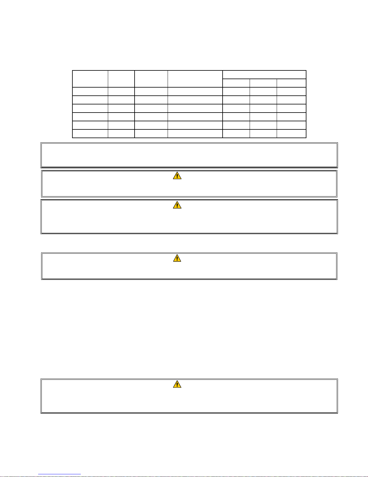
The three-phase supply plug for the elements is rated at 60 amps, 250 VAC and is NEMA configuration L15-60P. The
control and filter plug is rated at 20 amps, 120/208 VAC and is NEMA configuration L21-20P. Each fryer should have
its cord for the element supply on an individual circuit as well as the control cord.
WIRE
VOLTAGE PHASE
SERVICE
208 3 3 6 (16) 39 39 39
240 3 3 6 (16) 34 34 34
480 3 3 8 (10) 17 17 17
220/380 3 4 6 (16) 21 21 21
240/415 3 4 6 (16) 20 20 21
230/400 3 4 6 (16) 21 21 21
MIN.
SIZE
AWG
(mm2)
AMPS PER LEG
L1 L2 L3
NOTICE
If this appliance is permanently connected to fixed wiring, it must be connected by means of copper wires
having a temperature rating of not less than 167°F (75°C).
DANGER
This appliance must be connected to a power supply having the same voltage and phase as specified on the
rating plate located on the inside of the appliance door.
DANGER
All wiring connections for this appliance must be made in accordance with the wiring diagram(s) furnished
with the appliance. Refer to the wiring diagram(s) furnished with the appliance when installing or servicing
this equipment.
2.3 After Fryers Are Positioned at the Frying Station
DANGER
No structural material on the fryer should be altered or removed to accommodate placement of the fryer
under a hood. Questions? Call the Frymaster Service Hotline at 1-800-551-8633.
1. Once the fryer has been positioned at the frying station, use a carpenter’s level placed across the top of the
frypot to verify that the unit is level, both side-to-side and front-to-back.
To level fryers, adjust the casters being careful to ensure the fryer(s) are at the proper height in the frying
station.
The front right caster may be locked with setscrews that may need to be loosened to move into place. Once in
place, the caster setscrews can be locked with the caster wheel parallel to the fryer from front to back to ease
moving the fryer in and out of the hood for cleaning and preventing the caster from hitting the oil reservoir.
When the fryer is leveled in its final position, install the restraints provided by the KES to limit its movement so
that it does not depend on or transmit stress to the electrical conduit or connection. Install the restraints in
accordance with the provided instructions. If the restraints are disconnected for service or other reasons, they
must be reconnected before the fryer is used.
DANGER
Adequate means must be provided to limit the movement of this appliance without depending on or
transmitting stress to the electrical conduit. A restraint kit is provided with the fryer. If the restraint kit is
missing contact your local Frymaster Authorized Servicer (FAS).
2-3
Page 13
g
DANGER
Hot oil can cause severe burns. Avoid contact. Under all circumstances, oil must be removed from the fryer
before attempting to move it to avoid spills, falls, and severe burns. Fryers may tip and cause personal
injury if not secured in a stationary position.
2. Clean and fill frypot(s) to the bottom oil level line with cooking oil. (See Equipment Setup and Shutdown
Procedures in Chapter 3.)
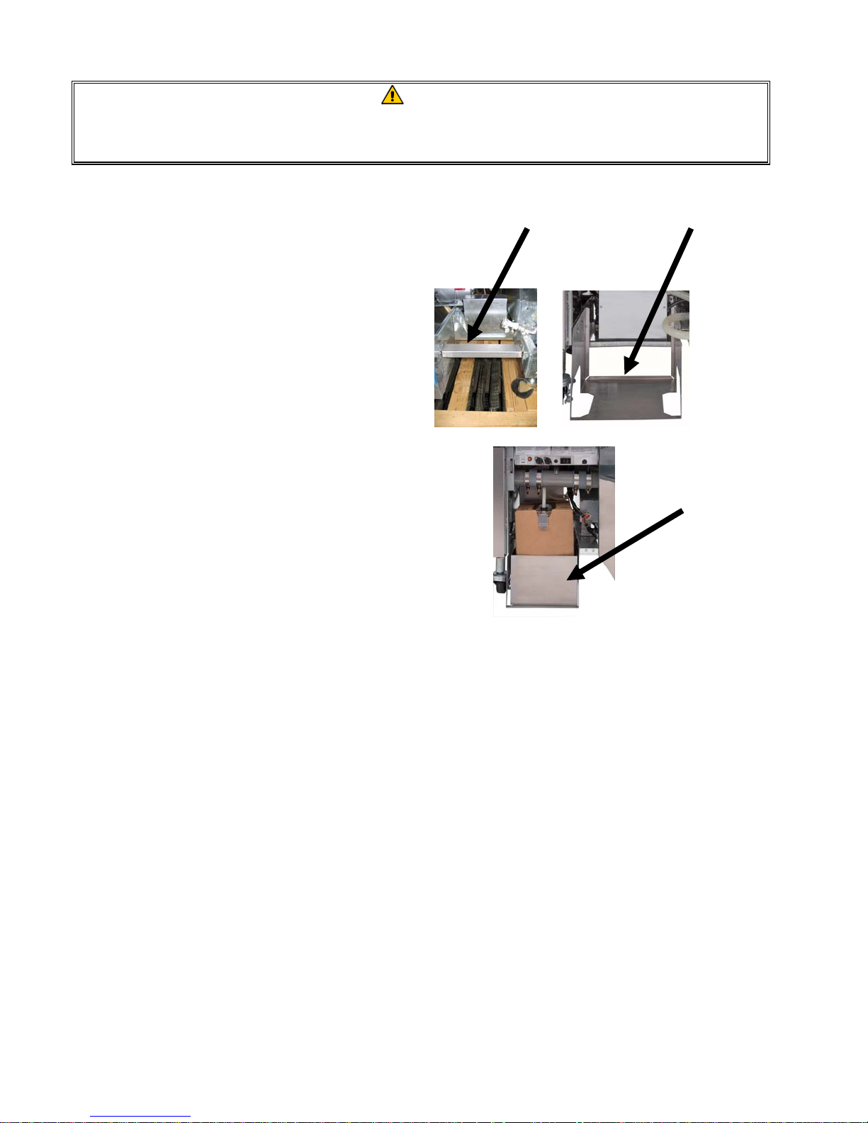
2.4 Installing the JIB Cradle
Open the fryer door (typically the far-right door or
third door) and remove the cross brace used for
shipping support by removing the four screws (see
Figure 1). Install the JIB cradle shipped (may differ in
appearance than one showed) in the accessories
pack with the screws that were removed in the
cross-brace removal step (see Figure 2). In some
configurations the cradle is optional. Install the
optional JIB splash shield to protect the bottom of
Figure 1 Figure 2
the JIB (see Figure 3). If using the solid shortening
option see Appendices B and C in the rear of this
manual for installation instructions.
Fi
ure 3
2-4
Page 14
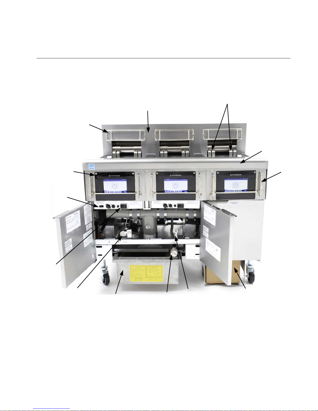
FINDING YOUR WAY AROUND THE BIELA14-T SERIES LOV™ ELECTRIC FRYER
Control Panel
(M4000
Controller
Shown)
BIELA14-T SERIES GEN III LOV™ ELECTRIC FRYER
CHAPTER 3: OPERATING INSTRUCTIONS
Elements
Tilt Housing
Basket Holder
Top Cap
Bezel
Reset
Switch
Power
Switch
Dispose Handle
and Lock
Filter Pan
Pre-Filter
Screen
Pre-Filter
Wrench
JIB Oil Reservoir
Behind Door (See
Sec. 3.3 Figure 1)
TYPICAL CONFIGURATION (BIELA314-T SHOWN)
NOTE: The appearance of your fryer may differ slightly from that
shown depending upon configuration and date of manufacture.
3–1
Page 15
3.1 Equipment Setup and Shutdown Procedures
WARNING
The on-site supervisor is responsible for ensuring that operators are made aware of the inherent hazards of
operating a hot oil filtering system, particularly the aspects of oil filtration, draining and cleaning
procedures.
CAUTION
Before turning on the fryer, ensure the frypot drain valves are closed. Remove the basket support rack(s), if
installed, and fill the frypot to the bottom OIL-LEVEL line. If solid shortening is being used, make sure it is
packed down into the bottom of the frypot.
3.1.1 Setup
DANGER
Never operate the appliance with an empty frypot. The frypot must be filled to the bottom OIL-LEVEL line
with water or oil before energizing the elements. Failure to do so will result in irreparable damage to the
elements and may cause a fire.
DANGER
Remove all drops of water from the frypot before filling with oil. Failure to do so will cause spattering of hot
liquid when the oil is heated to cooking temperature.
WARNING
The BIELA14-T is not intended to use solid shortening without a solid shortening kit installed. The use of
solid shortening without a solid shortening kit will clog the top off oil lines. The oil capacity of the BIELA14-T
LOV™ electric fryer is 32 lbs. (3.8 gallons/14.5 liters) at 70°F (21°C) for a full-vat and 18 lbs. (2.2 gallons/8.33
liters) at 70°F (21°C) for each half of a dual-vat.
1. Fill the frypot with cooking oil to the bottom OIL LEVEL line located on the rear of the frypot. This will allow for
oil expansion as heat is applied. Do not fill cold oil any higher than the bottom line; overflow may occur as heat
expands the oil. For bulk oil systems see Section 5.3.9 for instructions to fill the vat from bulk. If solid
shortening is used, make sure it is packed down into the bottom of the frypot.
2. Ensure that the power cord(s) is/are plugged and locked (if applicable) into the appropriate receptacle(s). Verify
that the face of the plug is flush with the outlet plate, with no portion of the prongs visible.
3. Ensure that the power is switched on. The master switch is located behind the left fryer door on the front of
the left contactor box.
4. Ensure that the controller is switched ON by pressing and holding the power button for 3 seconds. The fryer
will automatically enter the melt cycle mode if the frypot temperature is below 180ºF (82ºC) and will display
MELT CYCLE IN PROGRESS. (NOTE: During the melt cycle, the elements will energize for a few seconds, then
go out for a longer period.) The shortening must be stirred occasionally during the heating process to ensure
all the shortening in the vat is liquefied. When the frypot temperature reaches 180ºF (82ºC), the unit will
automatically switch to the heating mode and PREHEAT is displayed until within 15°F (9°C) of setpoint. The
elements will remain energized until the frypot temperature reaches the programmed cooking temperature.
Once the fryer reaches setpoint, the controller display changes to START and the fryer is ready for use.
5. Ensure that the oil level is at the top OIL LEVEL line when the oil is at its cooking temperature.
6. The maximum batch load for French Fries in oil or fat shall be no more than 1½ pounds or 0.7 kilograms.
3–2
Page 16
Shutdown
R
1. Place the controller ON/OFF switch in the OFF position to turn the fryer off.
2. Filter the oil and clean the fryers (See Chapters 5 and 6).
3. Clean the filter pan and replace the filter paper or pad. Do not leave solid shortening
in the filter pan over night.
4. Place the frypot covers on the frypots.
3.2 Operation
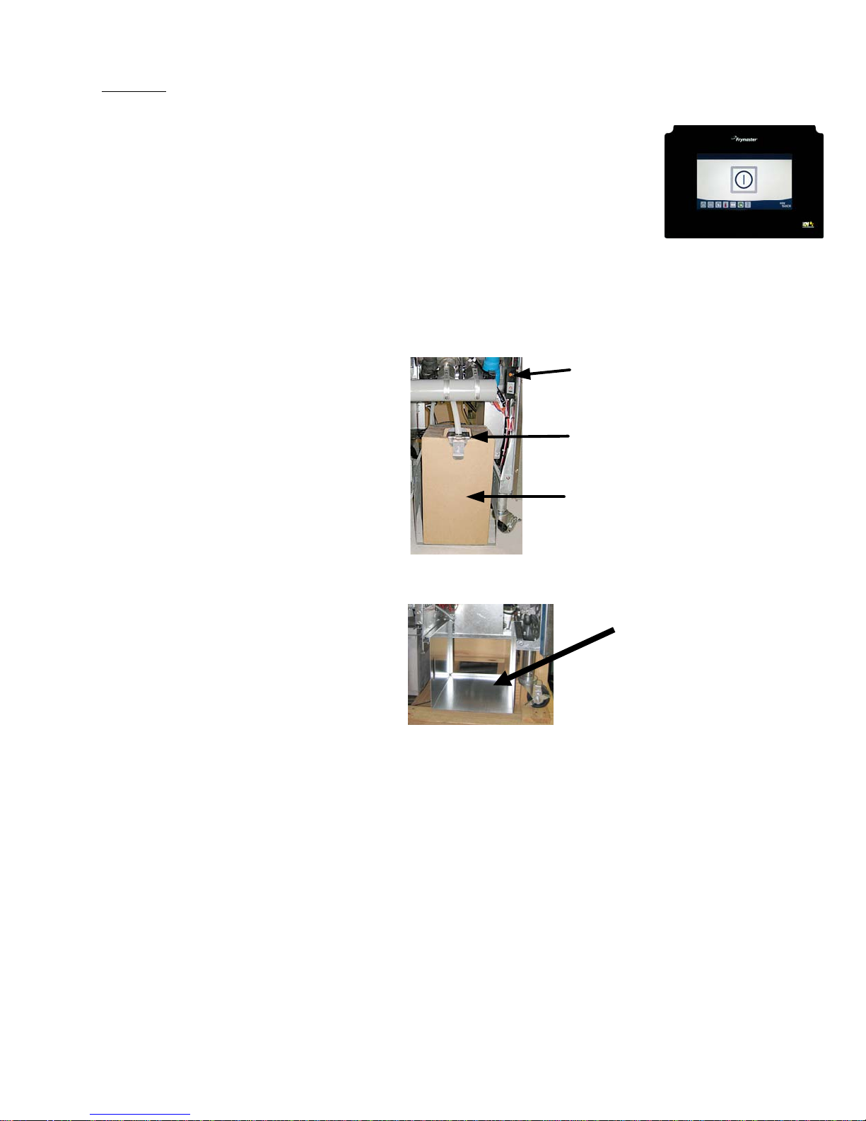
This fryer is equipped with M4000 controllers (illustrated right). Refer to the M4000
Controller Operating Instructions in Chapter 4 for the controller programming and operating
procedures.
Refer to Chapter 5 of this manual for operating instructions for the built-in filtration system.
3.3 Low Oil Volume Automatic Refill
When the Low Oil Volume (LOV™) system is
in place on the fryer, the frypot oil levels are
continually checked and topped off as
necessary from a reservoir in the cabinet.
JIB (Jug In Box) Reset
Switch: Resets the yellow
indicator after an oil change.
The reservoir holds a 35-pound box of oil.
In a typical operation this will last
approximately two days.
Components of the system are annotated at the
right (see Figure 1).
NOTE: The system is intended to top off the
frypots, not fill them. The frypots will require
Special Cap: Has plumbing
attached to draw oil from the
reservoir to the fryer vats.
Jug In Box (JIB):
The JIB is the
reservoir for the oil.
manual filling upon startup and after deep clean
(boil-out) unless a bulk fresh oil system is used.
Figure 1
3.3.1 Prepare the System for Use
Once the fryer is positioned under the hood
install the JIB (Jug In Box) basket shipped in the
accessories pack (see Figure 2). If using the solid
shortening option see Appendices B and C.
M4000 CONTROLLE
3.3.2 Changing the oil reservoir
Remove the original lid from the oil container and foil liner. Replace with the provided cap, which has connected
suction hardware. Ensure the feeder tube from the cap reaches to the bottom of the oil container.
Place the oil container inside the cabinet and slide it into place (as shown on the following page). Avoid catching the
suction hardware on the cabinet interior as the container is placed in the fryer.
The system is now ready for operation.
Figure 2
3–3
Page 17
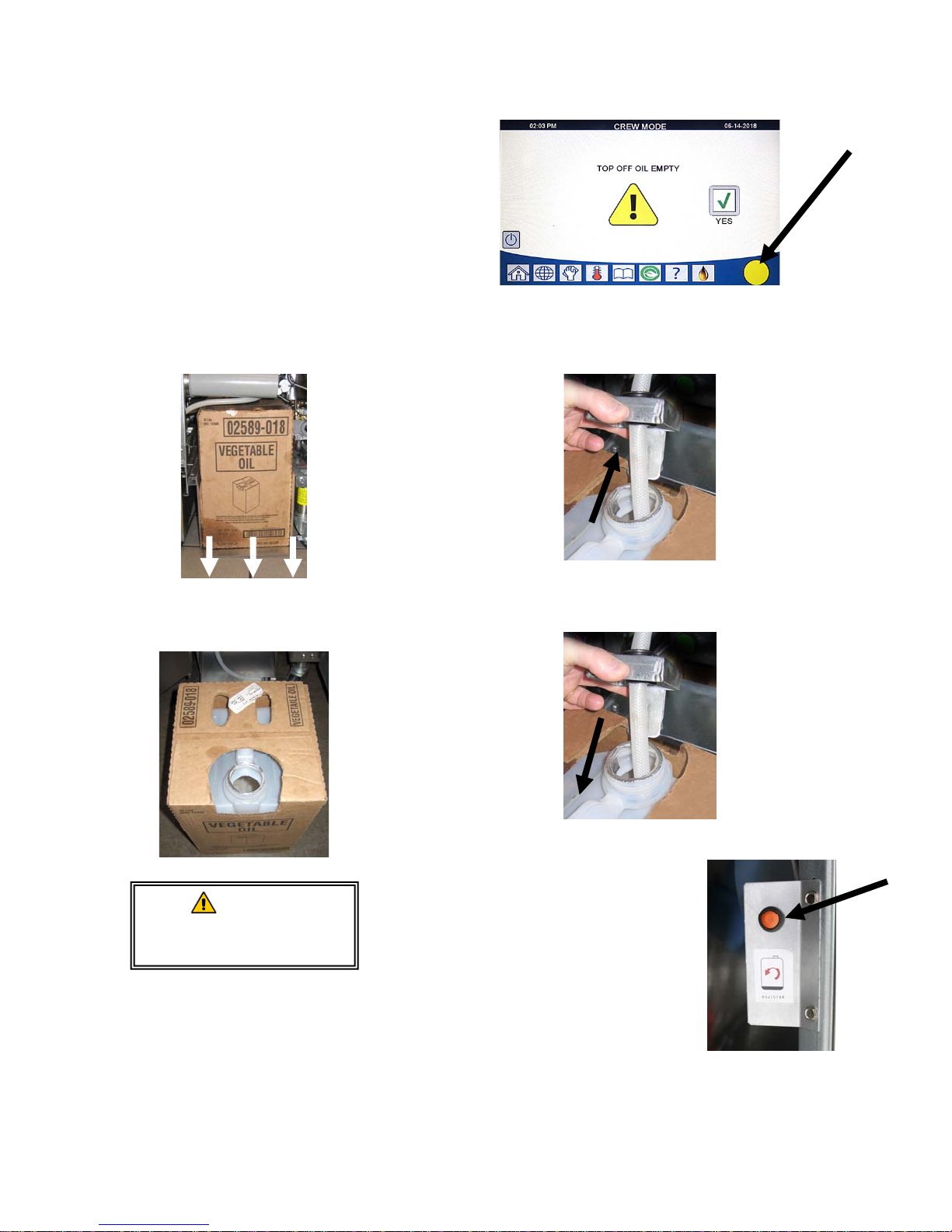
3.3.3 Routine Oil Changes
When the oil reservoir level is low, a yellow
indicator is activated (see Figure 3) and displays
TOP OFF OIL EMPTY. Press the check button to
clear the screen. Once the reservoir is refilled
and/or replaced, press and hold the orange reset
button next to the oil reservoir until the yellow
indicator is no longer illuminated. If using solid
shortening see Appendices B and C for
instructions.
1. Open the cabinet and slide the JIB from the
cabinet (see Figure 4).
Figure 3
Yellow indicator that oil reservoir is empty.
2. Remove the cap and pour any remaining oil in the container
into all fry vats equally (see Figure 5).
Figure 4
3. With the replacement jug upright remove the
cap and foil seal (see Figure 6).
Figure 6
WARNING
Do not add HOT or USED
oil to a JIB.
Figure 5
4. Put the tube in the new full container (see Figure 7).
Figure 7
5. Slide the JIB onto the shelf inside the
fryer cabinet (as seen in Figure 4).
6. Press the JIB reset switch to turn the
JIB yellow indicator on the M4000
controller off (see Figure
3.3.4 Bulk or Front Dispose Oil Systems
Instructions for installing and using bulk oil systems are found in Appendix A
located at the rear of this manual.
3–4
Figure 8
Page 18
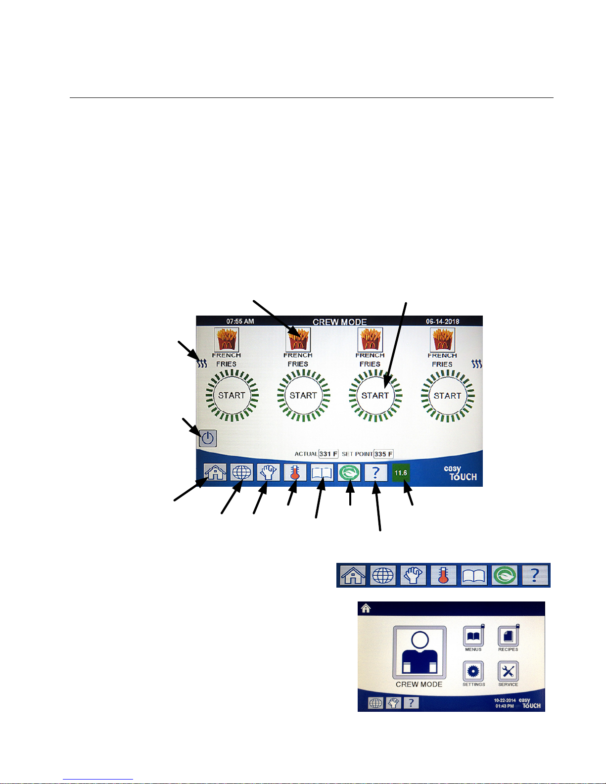
BIELA14-T SERIES GEN III LOV™ ELECTRIC FRYER
CHAPTER 4: M4000 CONTROLLER INSTRUCTIONS
4.1 M4000 General Information
Welcome to the M4000, an easy to use touch screen controller with the utility of 40-product menu capability. One
button push starts a cook cycle for a selected product. Just choose a menu item on a product button and press the
START button under the display showing the desired item. The controller can move seamlessly from McNuggets to
Crispy Chicken to any added menu item.
The M4000 will operate with electric and gas fryers, both full- and split-vat.
4.2 M4000 Button Description and Functions
4.2.1 Navigation Buttons
Product/Change Product
Start Cook/Cancel Alarm
Heat
Indicator
On‐Off
(Press and
Hold to
switch on.
Press to
switch off)
Home
Button
(Settings,
Recipes)
4.2.1.1 Main Menu Button Bar
The main menu button bar at the bottom of the screen is
used to navigate the various M4000 menus (see Figure 1).
4.2.1.2 Home Button
The home button is used to switch to the home screen (see
Figure 2). The home screen has Crew Mode, Menus, Recipes,
Settings and Service buttons.
Change
Language
Filter
Menu
Temp
Change
Menu
4-1
Energy
Saver
Information
Statistics
Figure 1
Figure 2
TPM
(Oil Quality)
Page 19
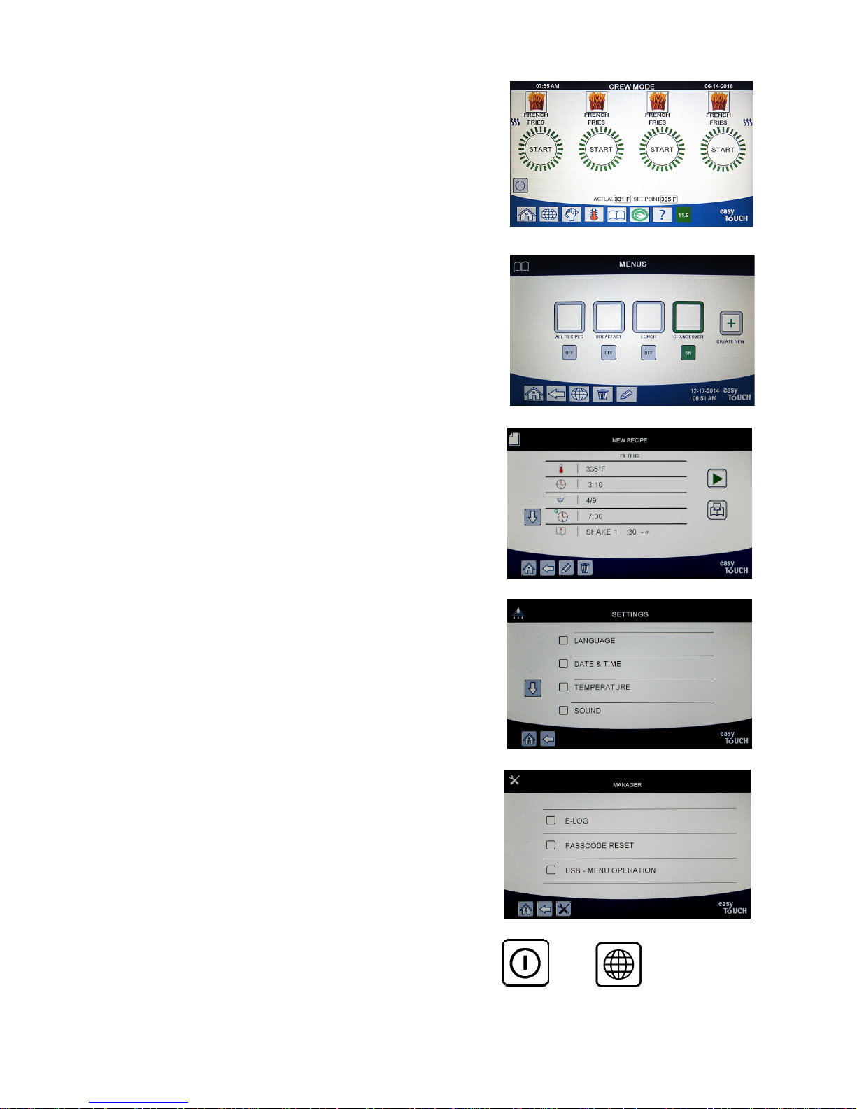
4.2.1.3 Crew Mode Button
The crew mode button switches from the home screen to the cooking
mode (see Figure 3).
4.2.1.4 Menus Button
The menus button is used to set up multiple menus with specific
products such as breakfast, lunch and changeover menus (See Figure
4).
4.2.1.5 Recipes Button
The recipes button allows editing or adding of products (see Figure 5).
4.2.1.6 Settings Button
The settings button allows access to edit the settings of the fryer (see
Figure 6).
4.2.1.7 Service Button
The service button allows access to service functions in the fryer (see
Figure 7).
During programming and other functions if no activity occurs within
one minute, the controller returns to the previous operation mode.
4.2.1.8 Power Button
Pressing and holding the power button for three (3) seconds soft
powers up the user interface and fryer. Pressing the power button
when the fryer is on turns the fryer off (see Figure 8).
4.2.1.9 Language Button
Pressing the language button switches between a primary language
and a secondary language, if the feature is configured in manager
settings (see Figure 9).
Figure 3
Figure 4
Figure 5
Figure 6
Figure 7
Figure 8
Figure 9
4-2
Page 20
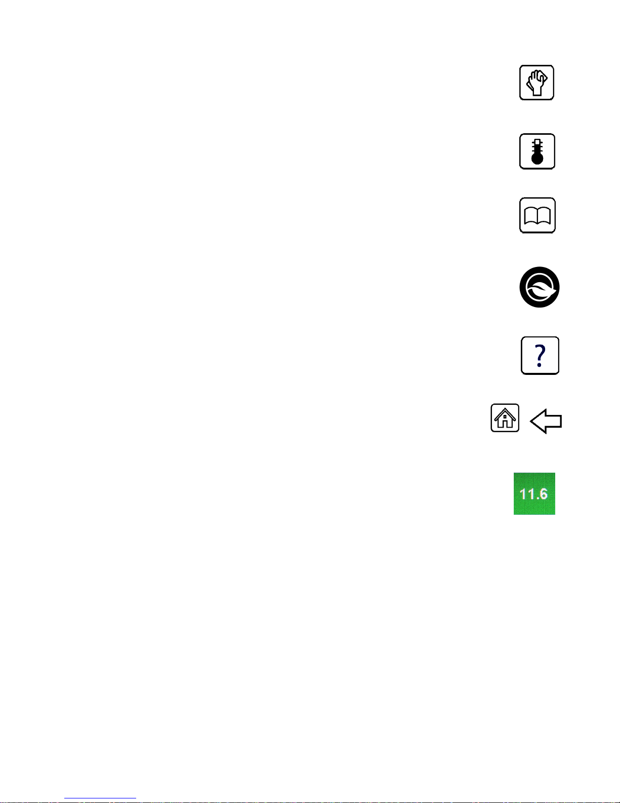
4.2.1.10 Filter Menu Button
Pressing the filter menu button provides access to the functions associated with filtering, disposing,
draining, filling as well as deep cleaning the vats (see Figure 10). If an auto filter is skipped the button
turns yellow until the filtration is completed.
4.2.1.11 Temperature Button
Pressing the temperature button displays the actual vat temperature and the setpoint temperature
(see Figure 11).
4.2.1.12 Menu Button
Pressing the menu button allows switching between different menus if configured (see Figure 12).
4.2.1.13 Energy Saver Button
Pressing the energy saver button switches the fryer from a standard setpoint to a lower temperature
setpoint when the fryer is idle, to save energy costs (see Figure 13).
4.2.1.14 Information Statistics Button
Pressing the information statistics button provides information on filter statistics, oil statistics, life
statistics, usage statistics, recovery time, last load statistics, and software versions (see Figure 14).
4.2.1.15 Escape Menu Items
To escape or back out of MENUS and SUB-MENUS, press the Home or Back arrow button
(see Figure 15).
4.2.1.16 TPM (Total Polar Materials) OQS (Oil Quality Sensor) Button
Pressing the TPM button when solid, displays the last 30 days of TPM/OQS readings (see Figure 16).
Pressing the TPM button when blinking, denotes it has been more than 24 hours since the last OQS
filter and will prompt for an OQS filter.
Figure 15
Figure 10
Figure 11
Figure 12
Figure 13
Figure 14
Figure 16
4-3
Page 21
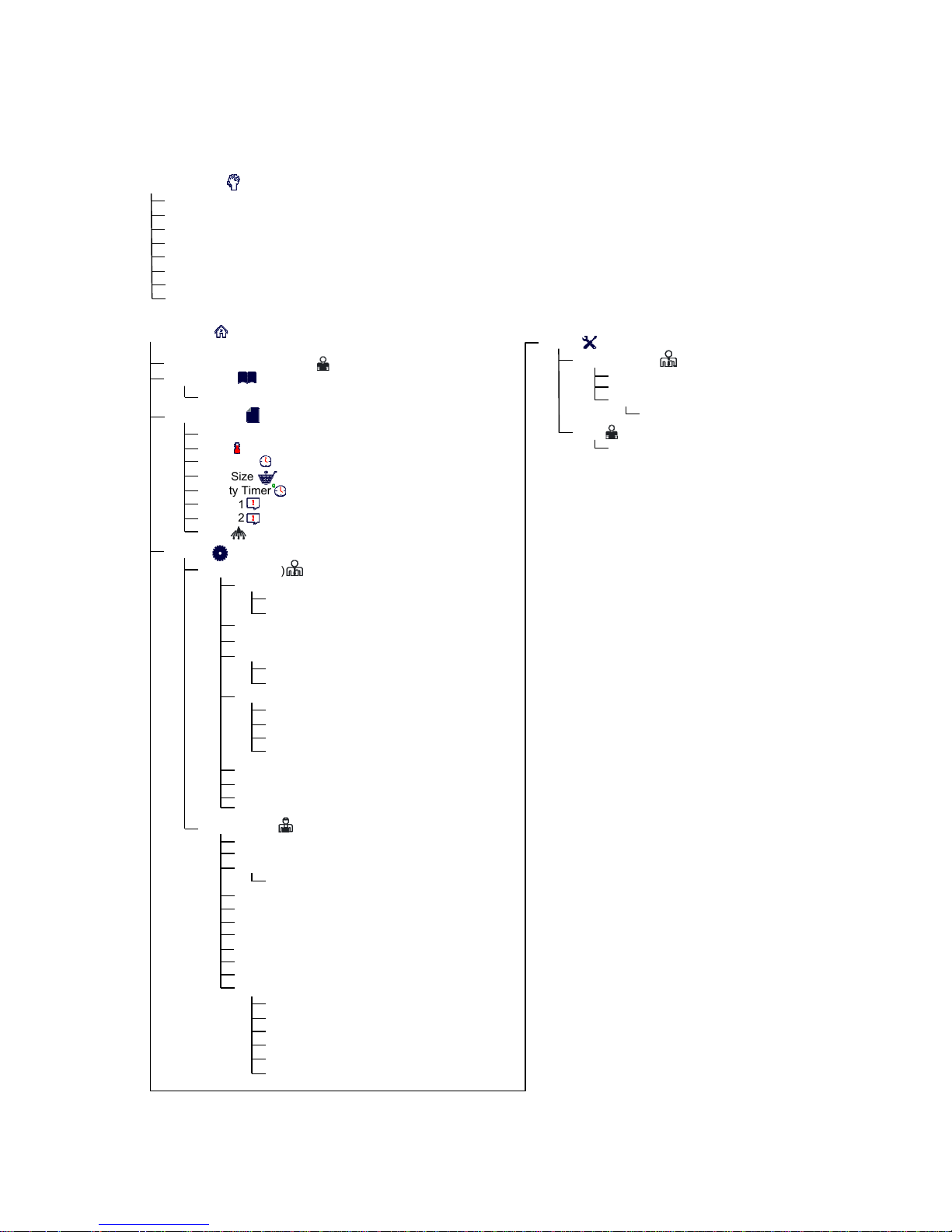
4.3 M4000 Menu Summary Tree
Reflected below are the major programming sections in the M4000 and the order in which submenu headings will
be found under the sections in the Installation and Operation Manual.
Filtration Menu
Auto Filtration
Maintenance Filter
Dispose Oil
Drain Oil
Fill Vat from Drain Pan
Fill Vat from Bulk (Bulk Only)
Oil Pan to Waste (Bulk Only)
Deep Clean
Home Button
Crew Mode (Cooking Mode)
Menus (1234)
Create New
Recipes (1234)
Product Name
Temp
Cook Time
Load Size
Quality Timer
Shake 1
Shake 2
Filter
Settings
Manager (1234)
Language
Date & Time
F° to C°/ C° to F° (Toggles Temperature Scale)
Sound
Filter Attributes
Energy Savings (Enabled, Temperature, Time)
Lane Assignments (# of Baskets)
Brightness
Screen Saver
Service (1650)
Locale (CE / Non-CE)
Energy Type (Gas / Electric)
Vat Type (Full / Split)
Oil System Type (JIB / Bulk)
Waste Oil (None / Bulk/Front Dispose)
Auto Top Off Vat (On / Off / User Prompted Top Off)
User Prompted Top Off Timer
ATO Delay Time
Filtration Time Settings
Filtration Type
OQS Setup
Service
Manager (4321)
E-Log
Passcode Setup
USB Menu Operation
Copy Menu from USB to Fryer
Crew
Hi-Limit Test
Primary
Secondary
Volume
Tone
Filter After (Cooks)
Filter Time (Hours)
Filter Lockout
Filtration Lockout Time
Basket Configuration
OQS (Enable/Disable)
Oil Type (Oil Curve)
Display Type (Number/Text)
Discard Now (TPM Value)
Discard Soon (TPM Offset Value)
Dispose Delay Timer
4-4
Page 22
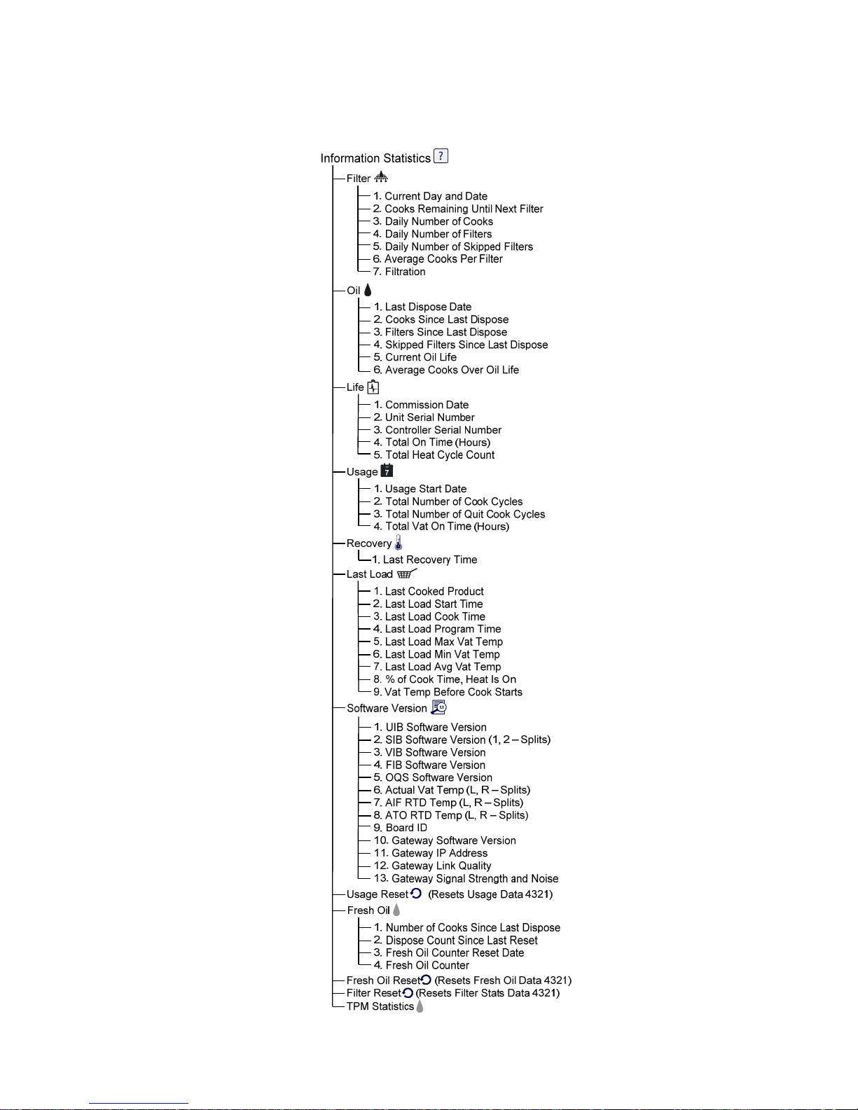
4.4 M4000 Information Summary Tree
Reflected below are the information statistics in the M4000 and the order in which submenu headings will be found
in the controller.
4-5
Page 23
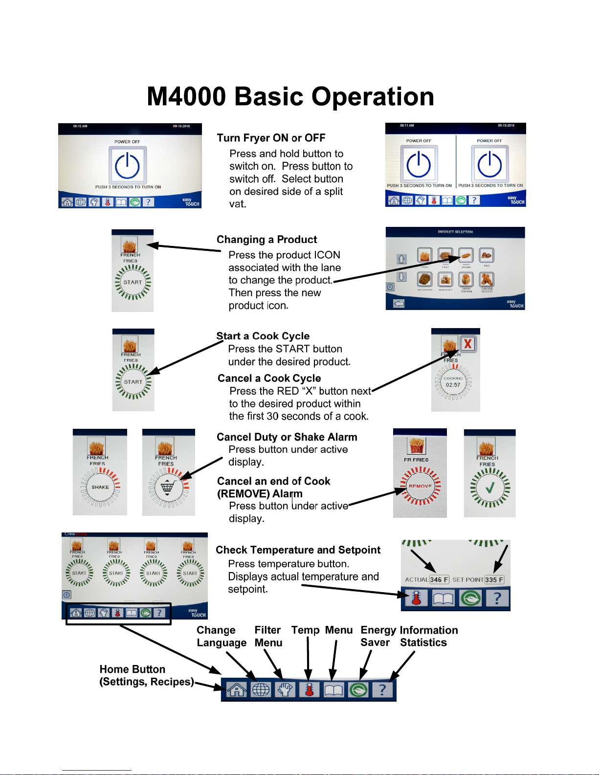
4.5 Basic Operation
4-6
Page 24

4.6 Cooking
4-7
Page 25
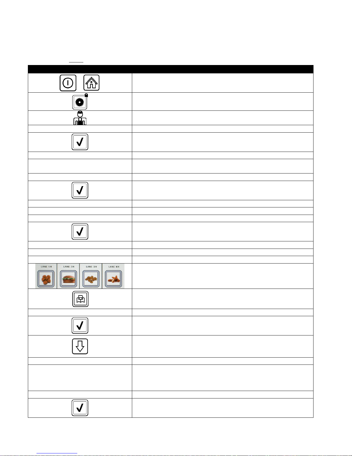
4.7 Fryer (Service) Setup Programming
It is necessary upon initial power up or when changing out a controller to configure the parameters for the fryer.
The setup includes locale, energy type, vat type, fresh oil type, waste oil type and auto top off settings. These
settings should ONLY be changed by a technician.
DISPLAY ACTION
1. With the controller at the off/standby position, press the Home
button.
2. Press the Settings button.
3. Press the Service button.
1 6 5 0 4. Enter 1650
5. Press the √ (check) button.
□ LOCALE 6. Press the Locale button.
CE NON-CE
SETUP COMPLETE RESET THE SYSTEM 8. No action.
7. Select CE or NON-CE. CE (European Conformity standards) or Non-
CE (non-European standards)
9. Press the √ (check) button.
□ ENERGY TYPE 10. Press the Energy Type button.
GAS ELECTRIC 11. Select GAS or ELECTRIC
SETUP COMPLETE RESET THE SYSTEM 12. No action.
13. Press the √ (check) button.
□ VAT TYPE 14. Press the Vat Type button.
FULL VAT SPLIT VAT 15. Select FULL VAT or SPLIT VAT.
4 16. Select Basket Configuration. Default is 4.
17. Press the Product icon and choose the desired product. Repeat for
other lanes.
18. Press the Save button when complete.
SETUP COMPLETE RESET THE SYSTEM 19. No action.
20. Press the √ (check) button.
21. Press the Down arrow button.
□ OIL SYSTEM TYPE 22. Press the Oil System Type button.
23. Select JIB or BULK.
JIB BULK
NOTE: A JIB (Jug in a Box) or BIB (Bag in a Box) is a disposable type oil
container. A bulk system has large storage oil tanks that are connected to
the fryer that fills an onboard reservoir.
SETUP COMPLETE RESET THE SYSTEM 24. No action.
25. Press the √ (check) button.
4-8
Page 26
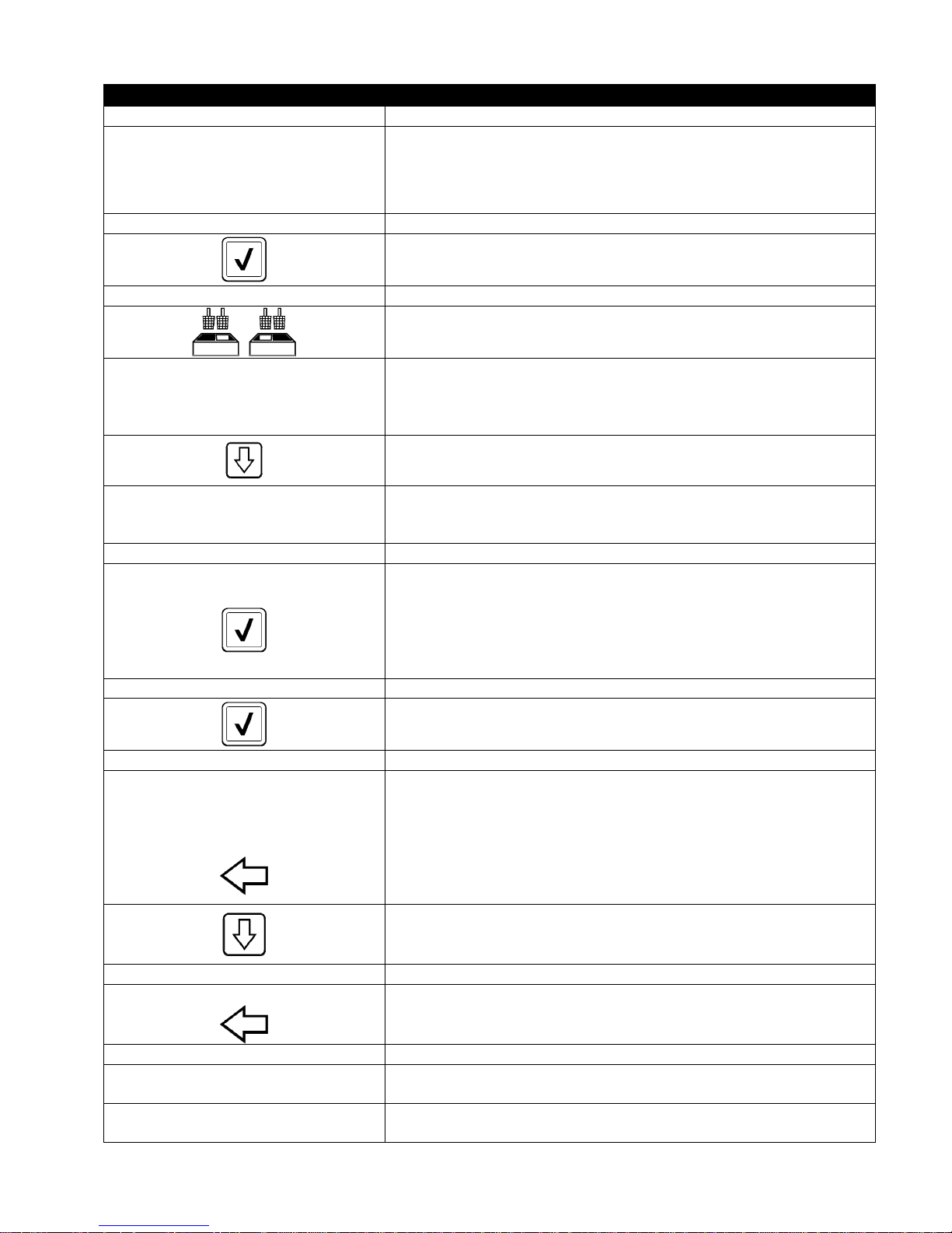
DISPLAY ACTION
□ WASTE OIL 26. Press the Waste Oil button.
27. Select NONE, BULK or FRONT DISPOSE.
NOTE: Select NONE if disposing oil into an MSDU or other METAL
NONE BULK FRONT DISPOSE
SETUP COMPLETE RESET THE SYSTEM 28. No action.
□ AUTO TOP OFF VAT 30. Press the Auto Top Off Vat button.
ON OFF USER PROMPTED TOP OFF
□ USER PROMPTED TOP OFF TIMER
□ ATO DELAY TIME 35. Press the ATO Delay time button.
30 MINUTES
SETUP COMPLETE 37. No action.
container. Select BULK if disposing oil into a bulk oil system, which has
large storage oil tanks that are connected to the fryer. Select FRONT
DISPOSE if disposing to a front type of disposal pan.
29. Press the √ (check) button.
31. Select LEFT VAT or RIGHT VAT for split vats.
32. Select ON for auto top off. Select OFF to disable auto top off.
Select USER PROMPTED TOP OFF for to disable auto top off and
prompt the user when to top off. If using user prompted top off, it
has to be enabled on ALL vats. Default is ON.
33. Press the Down arrow button.
34. Set the time to prompt again after acknowledging a top off prompt.
This setting is only available if USER PROMPTED TOP OFF is
selected in AUTO TOP OFF VAT. (Default is 30 minutes).
36. Press the time to change the delay time after the top off oil
reservoir has been changed before the system begins to top off.
Press the √ (check) button. Enter a value greater than 0 for solid
shortening. The default is 30 minutes to allow time for the
shortening to start melting before topping off begins. Set the value
to 0 for liquid shortening.
38. Press the smaller √ (check) button inside the SETUP COMPLETE box.
□ FILTRATION TIME SETTINGS 39. Press the Filtration Time Settings button.
□ POLISH TIME
□ DEEP CLEAN TIME
□ AUTO FILTER WASH TIME
□ MAINTENANCE FILTER WASH TIME
40. These settings should only be adjusted if instructed by the factory.
The default settings are:
□ POLISH TIME -300
□ DEEP CLEAN TIME -3600
□ AUTO FILTER WASH TIME -5
□ MAINTENANCE FILTER WASH TIME -30
Press the back button when complete.
41. Press the Down arrow button.
□ FILTRATION TYPE 42. Press the Filtration Type button.
SOLID LIQUID
43. Select SOLID if solid shortening is used. Select LIQUID if liquid
shortening is used. Press the back button when complete.
□ OQS SETUP 44. Press the OQS Setup button if an OQS sensor is installed.
□ OQS ENABLE/DISABLE
ENABLE DISABLE
45. Press OQS ENABLE/DISABLE button to enable/disable the OQS
sensor.
46. Select ENABLE to enable the OQS sensor or DISABLE to disable the
OQS sensor.
4-9
Page 27
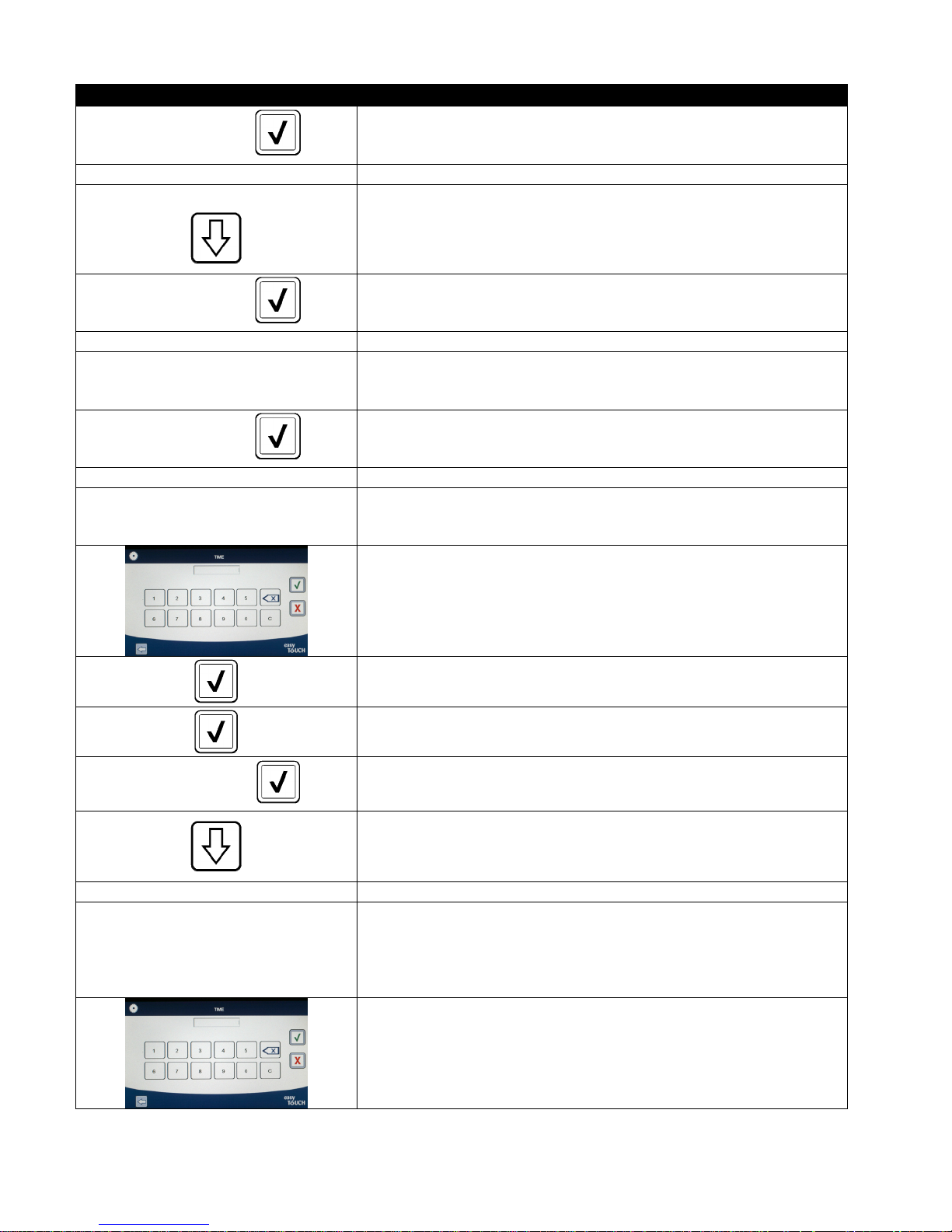
DISPLAY ACTION
47. Press the √ (check) button inside the SETUP COMPLETE box.
SETUP COMPLETE
□ OIL TYPE 48. Press the Oil Type button.
OC01v01, OC02v02, etc.
SETUP COMPLETE
□ DISPLAY TYPE 51. Press the Display Type button.
NUMBER TEXT
SETUP COMPLETE
□ DISCARD NOW 54. Press the Discard Now button.
TPM VALUE
49. Select the correct oil type curve. Press the down arrow button to
scroll to additional oil type curves. OC01vO1=F212,
OC02v02=MCSOL, OC12v02=F600
Ensure the oil type matches what the store is using.
50. Press the √ (check) button inside the SETUP COMPLETE box.
52. Select NUMBER or TEXT. NOTE: If set to NUMBER the Total Polar
Materials is shown as a number. If set to Text, only DISCARD
SOON/CONFIRM, OIL IS GOOD or DISCARD NOW is shown.
53. Press the √ (check) button inside the SETUP COMPLETE box.
55. Press the number above TPM Value. Once the TPM (Total Polar
Materials) value of the oil is attained, the fryer will prompt to
discard the oil.
56. Use the keypad to enter the TPM discard now value.
57. Press the √ (check) button once the value is entered.
58. Press the √ (check) button to save the value.
59. Press the √ (check) button inside the SETUP COMPLETE box.
SETUP COMPLETE
60. Press the down arrow button.
□ DISCARD SOON 61. Press the Discard Soon button.
62. Press the number above Discard Soon TPM Value. This value is
typically chosen as a number below the TPM Discard Now value.
TPM VALUE
This value will display the Discard Soon message when the TPM
Discard Soon value is attained. This serves as a notice to the staff
that the oil will need to be discarded soon.
63. Use the keypad to enter the TPM discard soon value.
4-10
Page 28
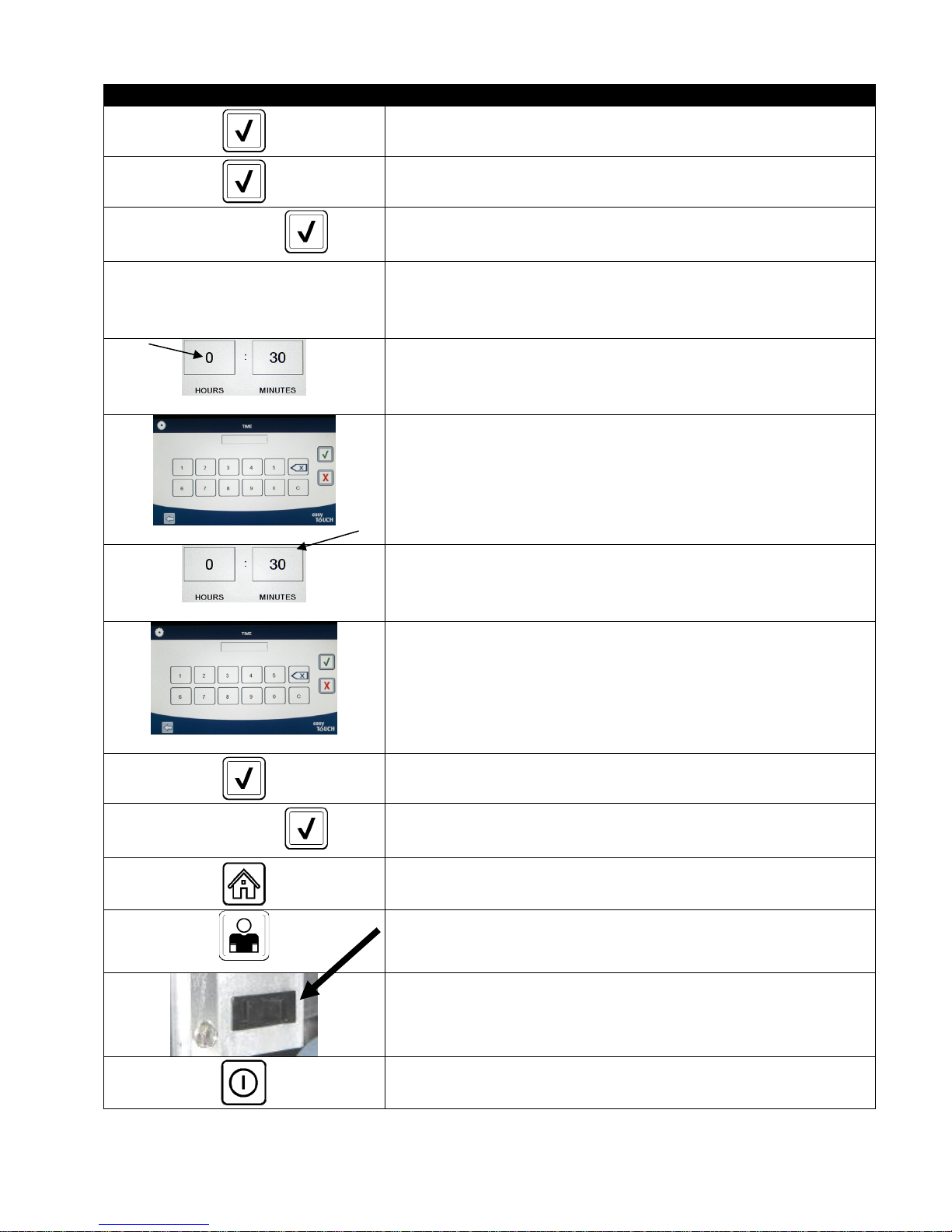
DISPLAY ACTION
64. Press the √ (check) button once the value is entered.
65. Press the √ (check) button to save the value.
66. Press the √ (check) button inside the SETUP COMPLETE box.
SETUP COMPLETE
67. Press the Dispose Delay Timer button. This is the amount of time
□ DISPOSE DELAY TIMER
once the DISCARD NOW prompt is displayed and bypassed before
the DISCARD NOW message returns. (Default is: 30 minutes.
Minimum value is :00 = DISABLED, maximum value is 4:00 hours.)
68. Press the hour’s box to enter a delay time in hours.
69. Using the key pad, enter the time in hours.
70. Press the minute’s box to enter a delay time in minutes.
71. Using the key pad enter the time in minutes.
72. Press the √ (check) button to save the value.
SETUP COMPLETE
CREW MODE
73. Press the √ (check) button inside the SETUP COMPLETE box.
74. Press the Home button.
75. Press the Crew Mode button.
76. Press and hold the reset switch inside the left door for thirty (30)
seconds.
77. The system reboots in approximately 45 seconds and returns to
off/standby mode.
4-11
Page 29
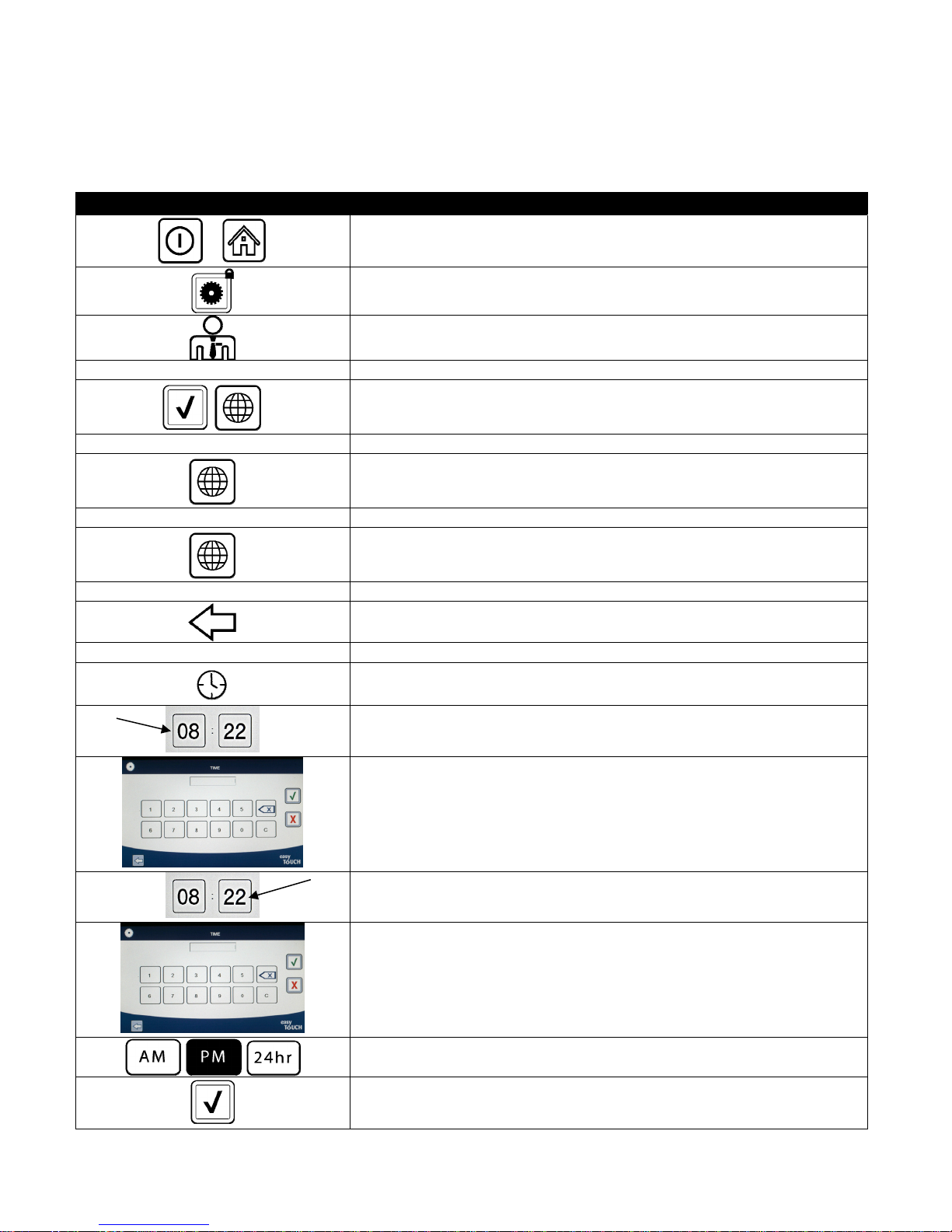
4.8 Fryer (Manager) Settings Programming
It is necessary upon initial power up or when changing out a controller to configure these local manager settings for
the fryer. The setup includes language, date and time, temperature scale, sound settings, filter settings, energy
savings, lane assignments and screen brightness. These settings should ONLY be changed by a manager or
technician.
DISPLAY ACTION
1. With the controller at the off/standby position, press the Home button.
2. Press the Settings button.
3. Press the Manager button.
1 2 3 4 4. Enter 1234
5. Press the √ (check) button.
□ LANGUAGE 6. Press the Language button.
7. Press the Primary Language button.
□ ENGLISH 8. Select the primary language desired.
9. Press the Secondary Language button.
□ SPANISH 10. Select the secondary language desired.
11. Press the Back button.
□ DATE & TIME 12. Press the Date & Time button.
13. Press the Set Time button
14. Press the hour’s box.
15. Using the key pad, enter the time in hours.
16. Press the minute’s box.
17. Using the key pad enter the time in minutes.
18. Press the AM, PM or 24HR button.
19. Press the √ (check) button.
4-12
Page 30
DISPLAY ACTION
SETUP COMPLETE 20. No action.
21. Press the smaller √ (check) button inside the SETUP COMPLETE box.
22. Press the Set Date button
23. Press the Date Format box to toggle between MM-DD-YY or DD-MM-YY.
24. At the top of the screen, the year is shown. Press the left or right arrow
2 0 1 4
MARCH
SETUP COMPLETE 27. No action.
to select the year.
25. Below the year is the month. Press the left or right arrow to select the
month.
26. Select the date using the numbered keys and press the √ (check)
button.
28. Press the smaller √ (check) button inside the SETUP COMPLETE box.
29. Press the DST (DAYLIGHT SAVINGS TIME) SETUP button.
□ DST ON/OFF 30. Press the DST ON/OFF button.
31. Select ON to enable DST or OFF to disable DST.
SETUP COMPLETE 32. No action.
33. Press the smaller √ (check) button inside the SETUP COMPLETE box.
□ DST SETTINGS 34. Press the DST SETTINGS button.
35. Select any of these and use the keypad to modify. The default settings
□ DST START MONTH
□ DST START SUNDAY
□ DST END MONTH
□ DST END SUNDAY
for the US are:
DST START MONTH -3
DST START SUNDAY -2
DST END MONTH -11
DST END SUNDAY -1
36. Press the √ (check) button when complete.
SETUP COMPLETE 37. No action.
38. Press the smaller √ (check) button inside the SETUP COMPLETE box.
39. Press the Back button three (3) times.
□ F° TO C°
40. Press the F° TO C° or F° TO C° button.
NOTE: F is used for Fahrenheit, C is used for Celsius
YES NO
CONFIRM
COMPLETED SUCCESSFULLY
41. Select YES to toggle the temperature scale.
42. Press the √ (check) button when complete.
4-13
Page 31
DISPLAY ACTION
□ SOUND 43. Press the Sound button.
44. Use the up down arrows to change the volume level and tone. Volume
has nine levels with 1 being the softest and 9 the loudest. Tone has
SETUP COMPLETE 46. No action.
□ FILTER ATTRIBUTES
□ FILTER AFTER
three frequencies from 1-3. Use different frequencies to distinguish
protein or French fry stations.
45. Press the √ (check) button when complete.
47. Press the smaller √ (check) button inside the SETUP COMPLETE box.
48. Press the Down button.
49. Press the Filter Attributes button.
The auto filtration mode uses two measures before prompting to filter.
One checks for cook cycles which is adjusted in the FILTER AFTER
setting and the other checks for time which is adjusted in the following
section FILTER TIME setting. The prompt for filtration is initiated by
whichever occurs first; either the number of cycles elapsed or time
elapsed.
50. Press the Filter After button.
The FILTER AFTER option is used to set the number of cooking cycles
which occur before the filtration prompt is displayed.
51. Press the √ (check) button to continue or press the number button and
enter the number of cooks and press the √ (check) button. (By default,
the full vat is set to 12 cooks and the split vat is set to 6 cooks.)
52. Press the √ (check) button.
SETUP COMPLETE 53. No action.
54. Press the smaller √ (check) button inside the SETUP COMPLETE box.
55. Press the Filter Time button.
□ FILTER TIME
SETUP COMPLETE 58. No action.
□ FILTER LOCKOUT
The Filter Time option is used to set the elapsed time before a filtration
prompt. This option is useful in lower volume stores, where filtration is
desired more often than the amount the cook cycles would generate.
56. Press the √ (check) button to continue or press the number button and
enter the number of hours in between filter prompts. (ex. after every
two hours, enter as 2) and press the √ (check) button. (By default, the
time is set to 0 hours.)
57. Press the √ (check) button.
59. Press the smaller √ (check) button inside the SETUP COMPLETE box.
60. Press the Filter Lockout button.
The Filter Lockout option is used to set the times in which the filter
prompt is disabled (ex. noon rush).
61. Select ON to enable FILTER LOCKOUT. Select OFF to disable FILTER
LOCKOUT.
4-14
Page 32
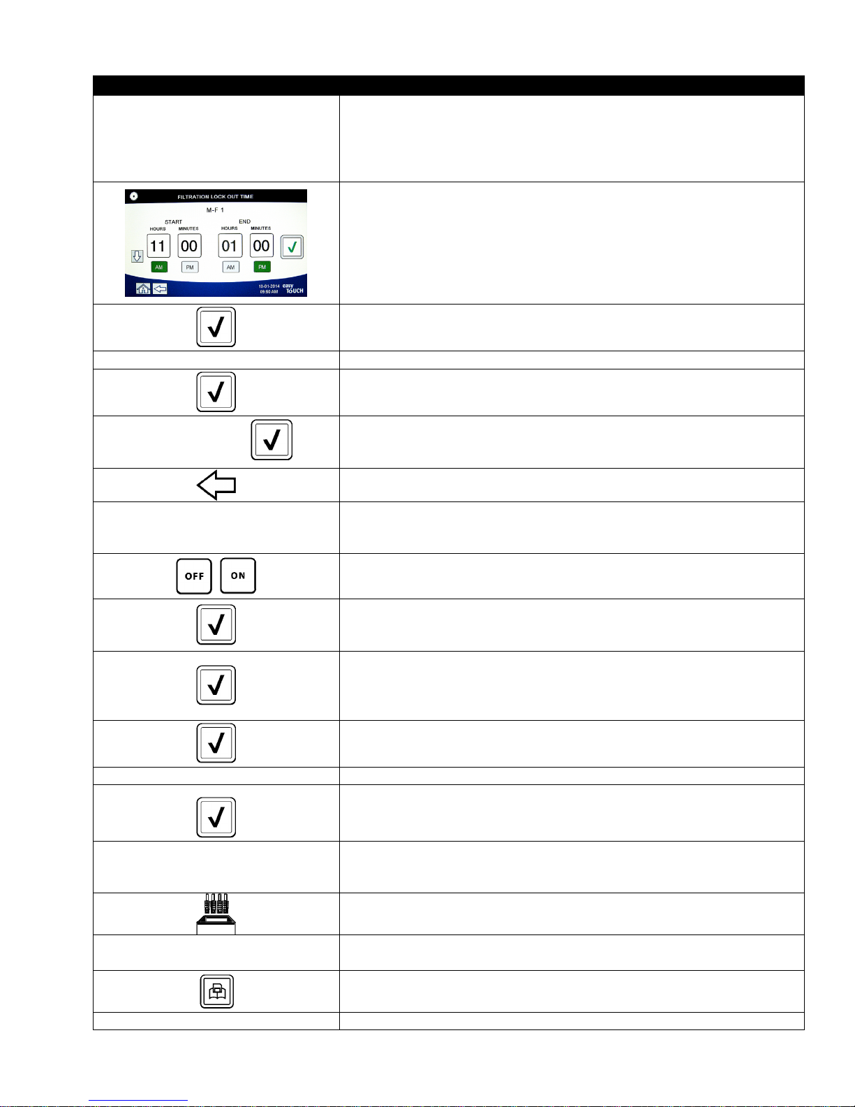
DISPLAY ACTION
62. Press the Filter Lockout Time button.
The Filtration Lockout Time option is used to set the times in which the
□ FILTRATION LOCKOUT TIME
SETUP COMPLETE 65. No action.
SETUP COMPLETE
filter prompt is disabled (ex. noon rush).
NOTE: If FILTER LOCKOUT is disabled (OFF), this option is grayed
out and not available.
63. Use the up down arrows to scroll between M-F 1 thru SUN 4. There are
a total of 12 periods which can be programmed for filter prompt
lockout. Select the field to edit the start and stop times of when the
filter prompt should be suspended. Select AM/PM. Once the times are
selected press the check button to save the setting.
left shows on Monday – Friday no filtering is desired during a lunch
rush from 11:00 AM until 1:00 PM.
64. Once the times are selected press the √ (check) button.
66. Press the smaller √ (check) button inside the SETUP COMPLETE box.
67. Press the √ (check) button inside the SETUP COMPLETE box.
68. Press the Back button.
(The example at the
)
69. Press the Energy Savings button.
□ ENERGY SAVINGS
The Energy Savings option is used during idle periods to lower the
frypot temperature to save energy.
70. Press the Enable button to toggle the Energy Saving option on or off.
71. Press the Set Back Temp button to change the setpoint of the Energy
Saving option. Use the number pad to enter the Energy Saving setpoint
temperature and press the √ (check) button.
72. Press the Idle Time button to change the amount of time in minutes the
vat sits idle before automatically entering the Energy Saving mode. Use
the number pad to enter the Energy Saving setpoint temperature and
press the √ (check) button.
73. Press the √ (check) button.
SETUP COMPLETE 74. No action.
75. Press the smaller √ (check) button inside the SETUP COMPLETE box.
76. Press the Lane Assignments button.
□ LANE ASSIGNMENTS
This is used to set the number of lanes or baskets each vat will use.
(Default is 4.)
77. Press the number 4 button.
SETUP COMPLETE RESET THE SYSTEM 80. No action.
78. Press the icon below each lane and choose the associated product to
cook in that lane.
79. Press the save button.
4-15
Page 33
DISPLAY ACTION
81. Press the smaller √ (check) button inside the SETUP COMPLETE RESET
THE SYSTEM box.
82. Press the Brightness button.
□ BRIGHTNESS
SETUP COMPLETE 84. No action.
□ SCREEN SAVER
SETUP COMPLETE 89. No action.
This is used to set the brightness of the screen. Use the up down
arrows to adjust. (Default is 100.)
83. Press the √ (check) button.
85. Press the smaller √ (check) button inside the SETUP COMPLETE box.
86. Press the Screen Saver button.
This is used to set the amount of time, after the controller is turned off,
before going into a screen saver mode. Use the up down arrows to
adjust time. (Default is 15 minutes.)
87. Use the up down arrows to change the brightness of the screen.
Brightness has nine levels with 100 being the brightest and 10 the
darkest.
88. Press the √ (check) button when complete.
90. Press the smaller √ (check) button inside the SETUP COMPLETE box.
91. Press the Back button.
92. Press the Home button.
93. Press the Crew Mode button.
94. Press and hold the reset switch inside the left door for thirty (30)
seconds.
95. The system reboots in approximately 45 seconds and returns to
off/standby mode.
CREW MODE
4-16
Page 34
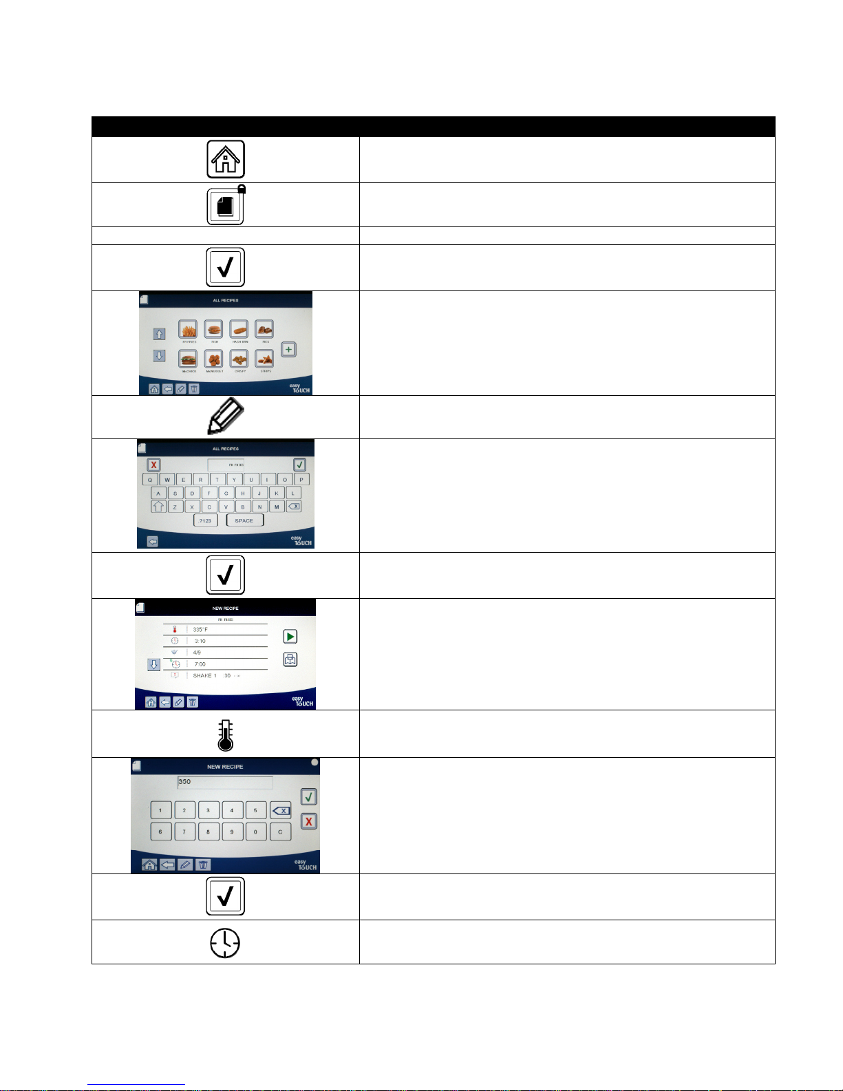
4.9 Adding or Editing Existing Products
This function is used to add additional products or edit existing products.
DISPLAY ACTION
1. Press the Home button.
2. Press the Recipes button.
1 2 3 4 3. Enter 1234
4. Press the √ (check) button.
5. Choose the product icon to edit or press the + to add a new
product.
6. Press the pencil icon at the bottom of the screen to edit an
existing product.
7. Enter or change the name of the product using the keyboard.
8. Press the √ (check) button.
9. This screen displays the current setpoint, cook time, load
compensation or sensitivity, quality timer, shake timers and
filter settings. To edit a parameter, press the item to edit.
10. To edit temperature, press the temp button.
11. Use the keypad to enter or edit the cook temperature for the
product.
12. Press the √ (check) button.
13. Press the cook time button.
4-17
Page 35
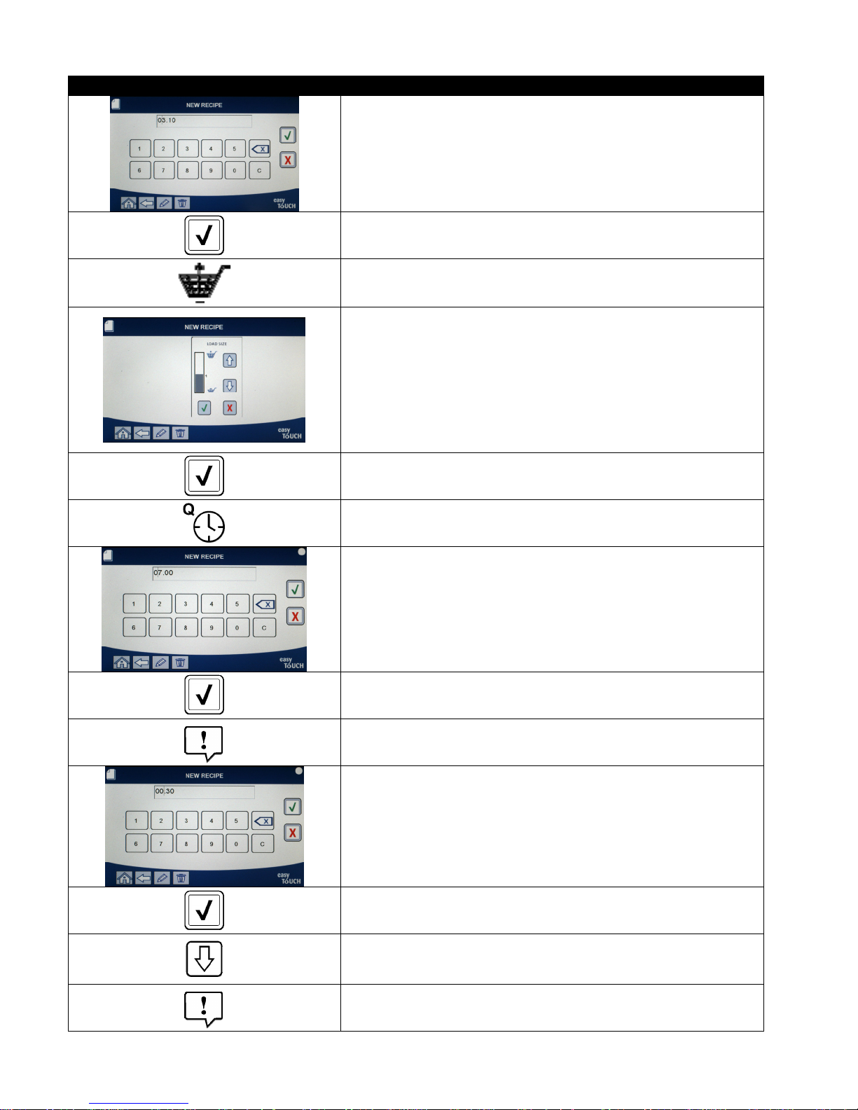
DISPLAY ACTION
14. Use the keypad to enter or edit the cook time in minutes and
seconds.
15. Press the √ (check) button.
16. Press the load compensation or sensitivity button.
17. Use the up and down arrows to change the load compensation
or sensitivity setting recommended for this product.
This setting allows the product compensation (sensitivity) to be
changed. Some menu items may need an adjustment,
depending on their cooking characteristics. NOTE: It is highly
recommended to NOT adjust this setting, as it could have
an adverse effect on the products cooking cycles.
The default setting for product compensation is set to four.
18. Press the √ (check) button.
19. Press the Quality Timer button.
20. Enter the time in minutes and seconds for the product hold
time.
21. Press the √ (check) button.
22. Press the Shake Timer 1 button.
23. Enter the time in minutes and seconds for the first shake to be
performed.
24. Press the √ (check) button.
25. Press the down arrow to scroll to more settings.
26. Press the Shake Timer 2 button if an additional shake is needed,
otherwise skip to step 30.
4-18
Page 36
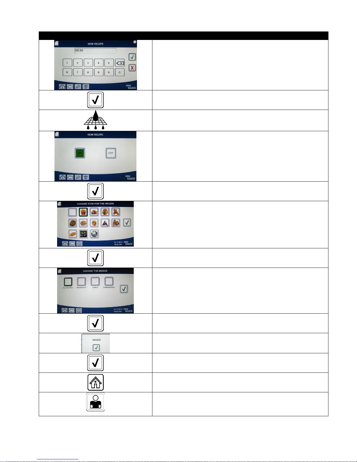
DISPLAY ACTION
27. Enter the time in minutes and seconds for the seconds shake to
be performed.
28. Press the √ (check) button.
29. Press the Filter button.
30. Ensure that the filter button is ON to enable auto filtration for
this product. This setting is used to prevent co-mingling of
product specific oils. For products such as FISH, select NO to
prevent auto filtration.
31. Press the √ (check) button.
32. Choose the icon to associate with the product recipe that is
being entered or edited.
33. Press the √ (check) button.
34. Choose the menu(s) to associate with the product recipe that is
being entered or edited.
35. Press the √ (check) button.
36. The controller displays SAVED.
37. Press the √ (check) button.
38. Select another product to edit or press the + key to add
additional products. If finished press the home button.
CREW MODE
39. Press the Crew Mode button to return to main screen.
4-19
Page 37
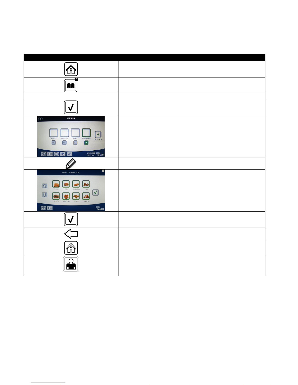
4.10 Adding or Editing Menus
This function is used to add or edit menus. Menus allow the operator to group certain products together. For
example, setting up a breakfast menu allows grouping of breakfast only products. This is helpful when switching
products by narrowing the number of products to choose from.
DISPLAY ACTION
1. Press the Home button.
2. Press the Menus button.
1 2 3 4 3. Enter 1234
4. Press the √ (check) button.
5. Select a menu by pressing the button above the ON/OFF button
to edit products (highlighted in green) or press the + button to
add a new menu. If adding a new menu, enter name of menu
on next screen and press the √ (check) button. If deleting a
menu, highlight the menu and press the trash can at the
bottom of the screen.
6. Press the pencil icon at the bottom of the screen to edit an
existing menu.
7. Select the desired products by pressing their icons to be added
to the chosen menu. The selected products will be highlighted
in green. To unselect a product, press the icon and the highlight
will change from green to gray.
8. Press the √ (check) button when finished to save selected
products to menu.
9. Press the Back button to edit additional menus starting with
step 5, otherwise advance to the next step
10. Press the Home button.
11. Press the Crew Mode button.
CREW MODE
4-20
Page 38
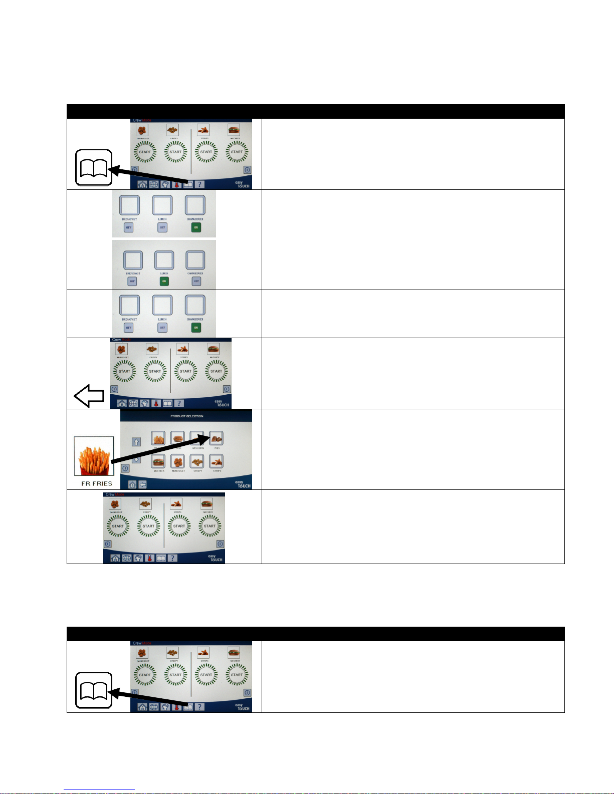
4.11 Changing from Breakfast Menu to Changeover or Lunch Menu
If separate menus are created for Breakfast, Changeover and Lunch, pressing the MENU button from the main
screen shall display menu change options. Pressing the desired menu shall switch the menus.
DISPLAY ACTION
1. Press the Menu button.
2. Press the ON/OFF button under Changeover or Lunch to switch
menus.
NOTE: Only one menu can be selected at a time.
3. Once the desired menu is selected, “ON” is highlighted under the
menu.
4. Press the back button to return to the main screen.
5. Press the product icon to switch products.
6. Display returns to main screen.
4.12 Changing from Lunch Menu to Changeover or Breakfast Menu
If separate menus are created for Breakfast, Changeover and Lunch, pressing the MENU button from the main
screen shall display menu change options. Pressing the desired menu shall switch the menus.
DISPLAY ACTION
1. Press the Menu button.
4-21
Page 39
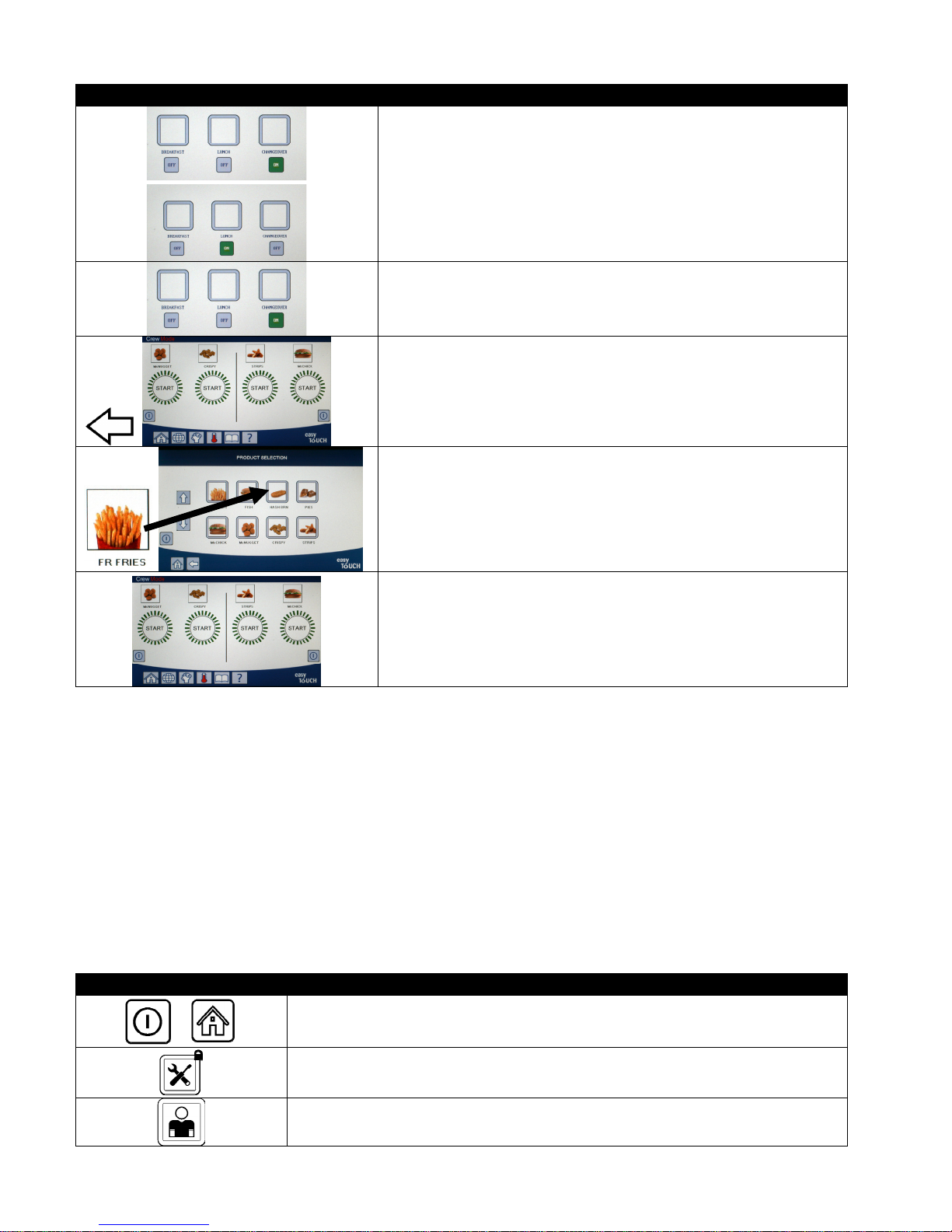
DISPLAY ACTION
2. Press the ON/OFF button under Breakfast or Changeover to
switch menus.
NOTE: Only one menu can be selected at a time.
3. Once the desired menu is selected, “ON” is highlighted under the
menu.
4. Press the back button to return to the main screen.
5. Press the product icon to switch products.
6. Display returns to main screen.
4.13 Service Tasks
Covered in this section are crew and manager service tasks used in stores such as High Limit Test, E-Log (error log),
password setup, and functions to copy menus to and from the fryer from USB using menu connect.
4.13.1 High Limit Test
The high-limit test mode is used to test the high limit circuit. The high-limit test will destroy the oil. It should only be
performed with old oil. Shut the fryer off and call for service immediately if the temperature reaches 460°F (238°C)
without the second high-limit tripping and the controller displays HIGH LIMIT FAILURE DISCONNECT POWER with an
alert tone during testing.
The test is cancelled at any time by turning the fryer off. When the fryer is turned back on, it returns to the
operating mode and displays the product.
DISPLAY ACTION
1. With the controller at the off/standby position, press the Home button.
2. Press the Service button.
3. Press the Crew button.
4-22
Page 40
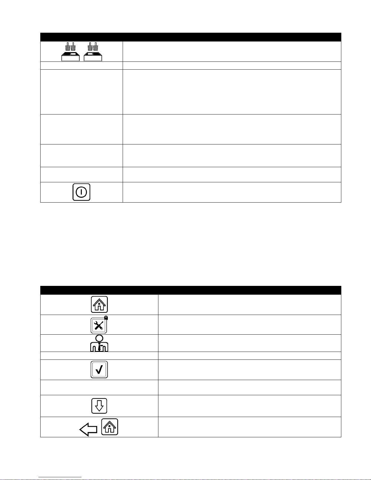
DISPLAY ACTION
4. Select LEFT VAT or RIGHT VAT for split vats.
PRESS AND HOLD 5. Press and hold the Press and Hold button to begin high limit test.
6. While pressing and holding the button the vat begins to heat. The controller
displays the actual vat temperature during the test. When the temperature
RELEASE
reaches 410°F ± 10° F (210°C ± 12°C)*, the controller displays HOT HI-1 (ex.
410F) and continues heating.
*NOTE: In controllers used in the European Union (those with the CE mark),
the temperature is 395°F (202°C) when the controller displays HOT HI-1.
7. While continuing to press and hold the button, the fryer continues heating
HOT HI-1
until the high limit opens. Generally, this happens once the temperature
reaches 423°F to 447°F (217°C to 231°C) for non-CE high limits and 405°F to
426°F (207°C to 219°C) for CE high limits.
8. Release the button. The vat stops heating and the controller displays the
HELP HI-2
current temperature setting until the temperature cools below 400°F (204°C).
Press the power button to cancel the alarm.
HIGH LIMIT FAILURE
DISCONNECT POWER
9. If the controller displays this message, disconnect power to the fryer and
immediately call for service.
10. After a high limit test, once the vat cools below 400°F (204°C), dispose of the
oil.
4.13.2 Manager Functions
4.13.2.1 E-Log
The E-LOG function is used to view the ten (10) most recent error codes encountered on the fryer. These codes are
displayed with the most recent errors displayed first. The error code, time and date are displayed.
If no errors exist, the controller is blank in this function. Errors are displayed with the side of the error if a split vat,
error code, time and date. An error code displaying an “L” indicates left side of a split vat while an “R” indicates right
side of a split vat where the error occurred (R E19 06:34AM 04/22/2014). An error code displaying a “G” indicates
this was a global error not specifically linked to a particular vat. Error codes are listed in section 7.6 of this manual.
DISPLAY ACTION
4 3 2 1 4. Enter 4321
□ E-LOG
1. Press the Home button.
2. Press the Service button.
3. Press the Manager button.
5. Press the √ (check) button.
6. Press the E-LOG button. The three most recent errors are
shown.
7. Press the Down button. The next three errors are shown.
Continue pressing the down arrow to view additional errors.
8. Press the Back button to return to menu or press the Home
button to exit.
4-23
Page 41
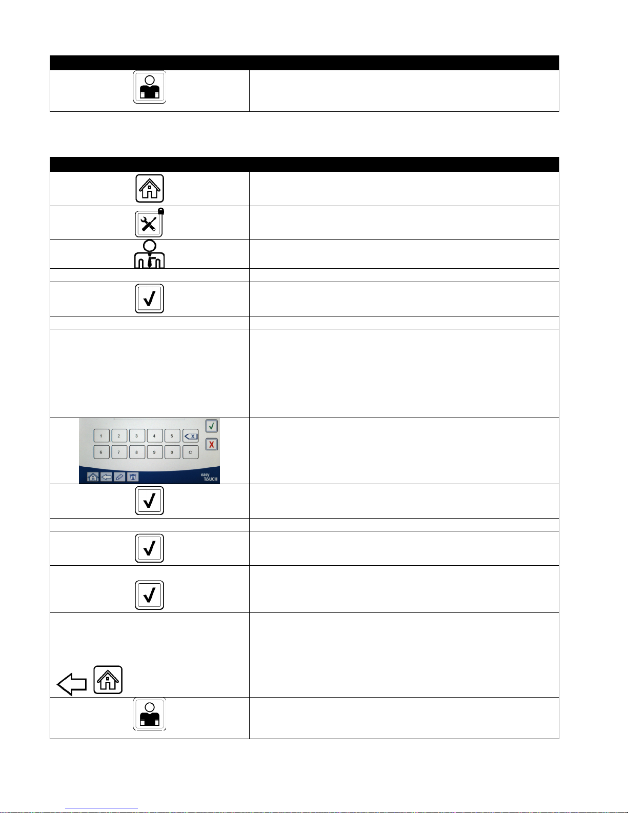
DISPLAY ACTION
CREW MODE
4.13.2.2 Passcode Setup
The password mode allows a restaurant manager to change passwords for various modes.
9. Press the Crew Mode button.
DISPLAY ACTION
1. Press the Home button.
2. Press the Service button.
3. Press the Manager button.
4 3 2 1 4. Enter 4321
5. Press the √ (check) button.
□ PASSCODE SETUP 6. Press the PASSCODE SETUP button.
7. Select the desired passcode to modify. Use the down arrow to
□ MENUS
□ RECIPES
□ SETTINGS MANAGER
□ DIAGNOSTICS MANAGER
scroll to additional setting.
Defaults are:
MENUS 1234
RECIPES 1234
SETTINGS MANAGER 1234
DIAGNOSTICS MANAGER 4321
RETYPE PASSWORD 10. Use the keypad to enter the new passcode again to verify.
PASSCODE SETUP SUCCESSFUL
□ MENUS
□ RECIPES
□ SETTINGS MANAGER
□ DIAGNOSTICS MANAGER
CREW MODE
8. Use the keypad to enter new passcode for the selected item.
9. Press the √ (check) button.
11. Press the √ (check) button.
12. Press the √ (check) button.
13. Press the Back button to return to menu or press the Home
button to exit.
14. Press the Crew Mode button.
4-24
Page 42
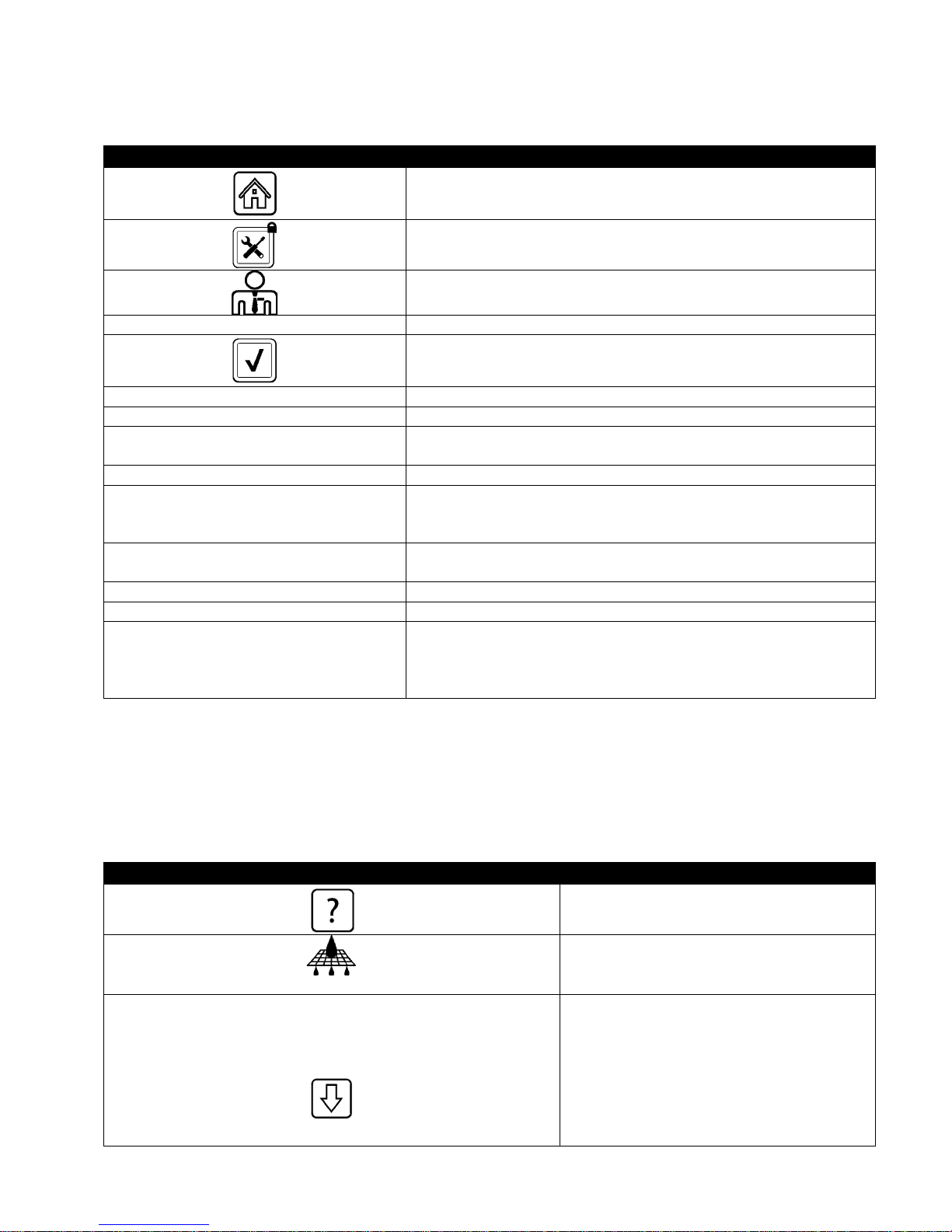
4.13.2.3 USB – Menu Operation
This option allows the ability to upload menus to the controller. This allows products to be created in MenuSync to
be saved to a USB drive and uploaded to the fryer.
DISPLAY ACTION
1. Press the Home button.
2. Press the Service button.
3. Press the Manager button.
4 3 2 1 4. Enter 4321
5. Press the √ (check) button.
□ USB – MENU OPERATION 6. Press the USB – MENU OPERATION button.
□ COPY MENU FROM USB TO FRYER 7. Press the COPY MENU FROM USB TO FRYER button.
INSERT USB…
8. Insert the USB drive into the connector behind the far-left fryer
door.
IS USB INSERTED? YES NO 9. Press YES once the USB drive is inserted.
READING FILE FROM USB
PLEASE DO NOT REMOVE USB WHILE
10. No action required.
READING
UI-UI MENU DATA TRANSFER IN
PROGRESS
11. No action required while the file is loading.
MENU UPGRADE IN PROGRESS 12. No action required while the upgrade is in progress.
UPGRADE COMPLETE? YES 13. Press YES.
14. Remove the USB drive and power cycle the entire fryer battery
MENU UPGRADE COMPLETED, REMOVE
THE USB AND RESTART THE SYSTEM.
using the reset switch behind the far-left fryer door below the
USB connector. NOTE: Ensure the switch is pressed and held
for at least 30 seconds.
4.14 Information Statistics
4.14.1 Filter Statistics
The filter statistics function is used to view the number of cooks remaining until the next filter, the number of cooks
per vat, the number of filters per vat, the number of skipped or bypassed filters per vat and the average number of
cook cycles per filter per day.
DISPLAY ACTION
□ DAY 1
□ DAY 2
□ DAY 3
□ DAY 4
1. Press the Information button.
2. Press the Filter button.
3. Select and press the desired day. Press
the down arrow to scroll back additional
days.
4-25
Page 43
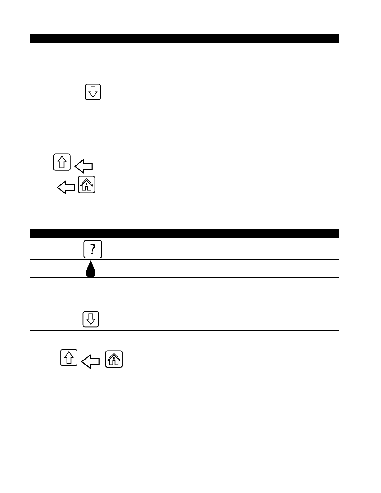
DISPLAY ACTION
1. DAY AND DATE (Day and date of filter statistics displayed)
2. COOKS REMAINING UNTIL NEXT FILTER (Number of times
cooks that remain until the next filter prompt.)
3. DAILY NUMBER OF COOKS (Number of cooks that day)
4. DAILY NUMBER OF FILTERS (Number of times vat filtered for a
4. Press the down arrow to scroll to more
statistics.
particular day)
5. DAILY NUMBER OF SKIPPED FILTERS (Number of times filter
was bypassed that day.)
6. AVERAGE COOKS PER FILTER - (Average number of cook cycles
per filter that day)
7. FILTRATION – (Displays if filtration is enabled or disabled.
Diagnostic tool to determine status of FIB board.)
5. Press the up arrow to scroll up or the
back button to return to select another
day.
6. Press the back button to return to menu
or the home button to exit.
4.14.2 Oil Statistics
The oil statistics function is used to view the date of last dispose, the number of cooks since last dispose, filters
since last dispose, skipped filters since last dispose, current oil life and average number of cooks over the oil life.
DISPLAY ACTION
1. Press the Information button.
2. Press the Oil button.
1. LAST DISPOSE DATE
2. COOKS SINCE LAST DISPOSE
3. FILTERS SINCE LAST DISPOSE
4. SKIPPED FILTERS SINCE LAST DISPOSE
5. CURRENT OIL LIFE
6. AVERAGE COOKS OVER OIL LIFE
3. Press the down arrow to scroll to more statistics.
4. Press the up arrow to scroll up; the back button to return to
menu or the home button to exit.
4-26
Page 44
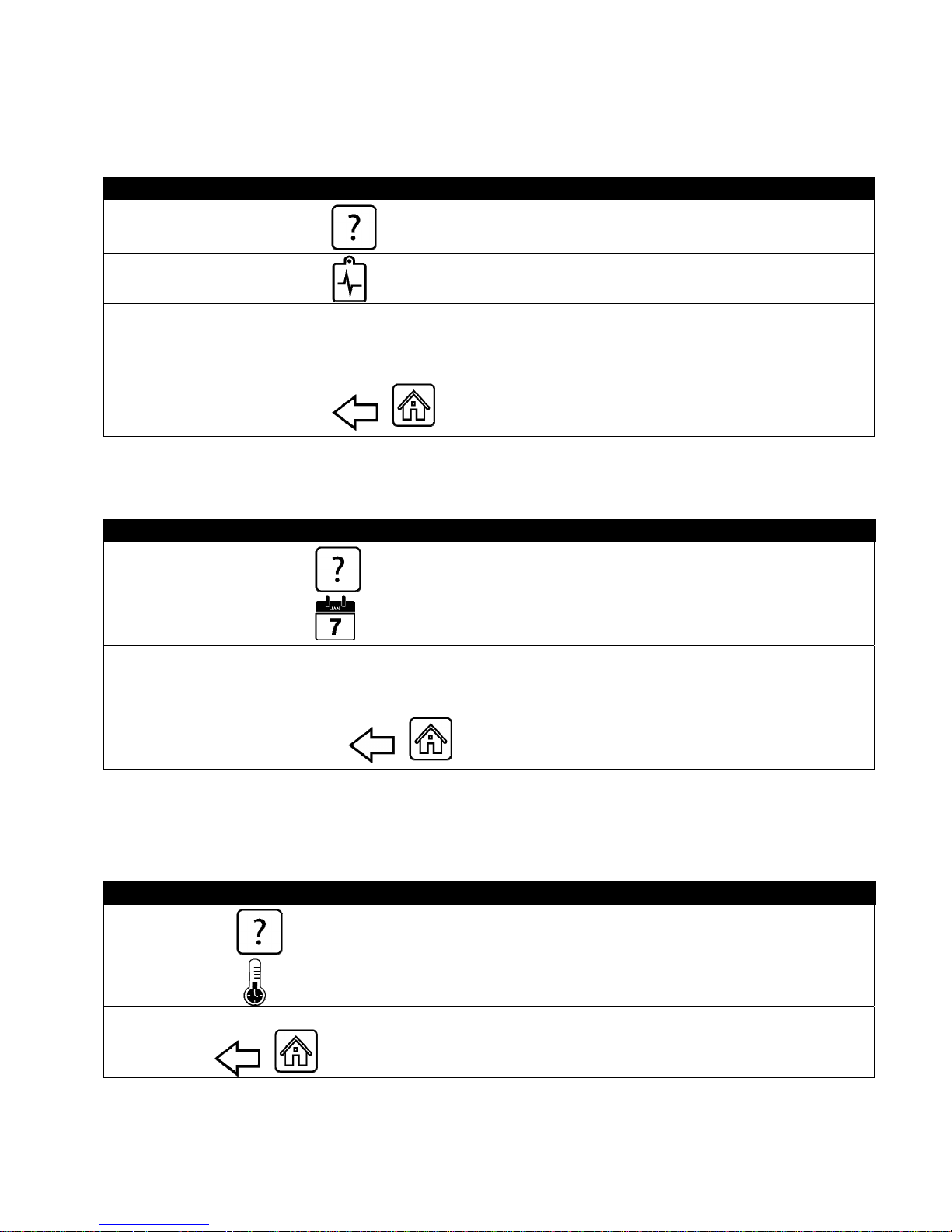
4.14.3 Life Statistics
The life statistics function is used to view the commission date of the fryer which is automatically set once the fryer
has completed 25 cooks, the serial number of the controller, the total time the fryer has operated in hours and the
total heat cycle count of the fryer (the amount of times the controller has turned the heat on/off).
DISPLAY ACTION
1. Press the Information button.
2. Press the Life Stats button.
1. COMMISSION DATE
2. UNIT SERIAL NUMBER
3. CONTROLLER SERIAL NUMBER
4. TOTAL ON TIME (HOURS)
3. Press the back button to return to
menu or the home button to exit.
5. TOTAL HEAT CYCLE COUNT
4.14.4 Usage Statistics
The usage statistics displays total cook cycles per vat, number of cook cycles per vat, number of cook cycles exited
prior to completion, the number of hours the vat(s) have been on and the date of last usage reset.
DISPLAY ACTION
1. Press the Information button.
2. Press the Usage Stats button.
1. USAGE START DATE
2. TOTAL NUMBER OF COOK CYCLES
3. TOTAL NUMBER OF QUIT COOK CYCLES
4. TOTAL VAT ON TIME (HOURS)
4.14.5 Recovery Time
Recovery is used to determine if the fryer is operating correctly. Recovery is the time required for the fryer to raise
the temperature of the oil 50°F (28°C) between 250°F (121°C) and 300°F (149°C). Maximum recovery time should
not exceed 1:40 for electric or 3:15 for gas.
DISPLAY ACTION
3. Press the back button to return
to menu or the home button to
exit.
1. LAST RECOVERY TIME
1. Press the Information button.
2. Press the Recovery button. The time is displayed in
minutes and seconds.
3. Press the back button to return to menu or the home
button to exit.
4-27
Page 45
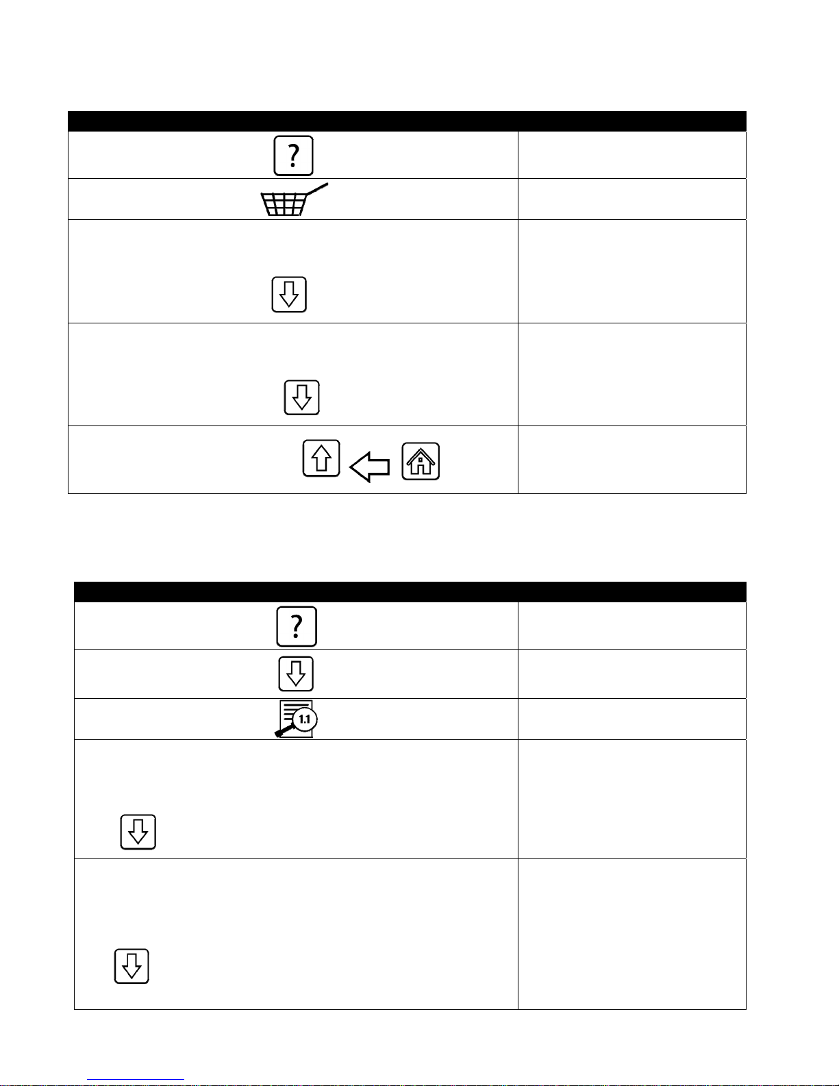
4.14.6 Last Load Statistics
The last load statistics provides data for the last cook cycle.
DISPLAY ACTION
1. Press the Information button.
2. Press the Last Load button.
1. LAST COOKED PRODUCT
2. LAST LOAD START TIME
3. LAST LOAD COOK TIME
3. Press the down arrow to scroll
4. LAST LOAD PROGRAM TIME
to more statistics.
5. LAST LOAD MAX VAT TEMP
6. LAST LOAD MIN VAT TEMP
7. LAST LOAD AVG VAT TEMP
4. Press the down arrow to scroll
to more statistics.
8. % OF COOK TIME, HEAT IS ON
5. Press the up arrow to scroll
up; the back button to return
9. VAT TEMP BEFORE COOK STARTS
4.14.7 Software Version
to menu or the home button
to exit.
The software version function provides the software versions of the controller and circuit boards.in the fryer
system; the values of the temperature probe, the AIF RTD probe and the ATO RTD probe.
DISPLAY ACTION
1. Press the Information button.
1. UIB SOFTWARE VERSION
2. SIB SOFTWARE VERSION
3. VIB SOFTWARE VERSION
4. FIB SOFTWARE VERSION
5. OQS SOFTWARE VERSION
6. ACTUAL VAT TEMP
7. AIF RTD TEMP
8. ATO RTD TEMP
9. BOARD ID
2. Press the down arrow button.
3. Press Software Version button.
4. Press the down arrow to scroll
to additional software
versions, probe temperatures
and information. NOTE: Split
vats will have an SIB2 and
left and right vat AIF, and
ATO temperatures.
5. Press the down arrow to scroll
to additional software versions
and information.
4-28
Page 46
DISPLAY ACTION
10. GATEWAY SOFTWARE VERSION
11. GATEWAY IP ADDRESS
12. GATEWAY LINK QUALITY
13. GATEWAY SIGNAL STRENGTH AND NOISE
6. Press the up arrow to scroll
up; the back button to return
to menu or the home button
to exit.
4.14.8 Reset Usage Statistics
The reset function resets all usage data in the usage statistics.
DISPLAY ACTION
1. Press the Information button.
2. Press the down arrow button.
3. Press Reset Usage button.
4 3 2 1 4. Enter 4321
5. Press the √ (check) button.
ALL USAGE DATA HAS BEEN RESET 6. Press the √ (check) button.
7. Press the up arrow to scroll up; the back button to
return to menu or the home button to exit.
4.14.9 Fresh Oil Statistics
The fresh oil statistics function is used to view information on the current fresh oil.
DISPLAY ACTION
1. Press the Information button.
2. Press the down arrow button.
3. Press the Fresh Oil button.
1. NUMBER OF COOKS SINCE LAST DISPOSE
2. DISPOSE COUNT COOKS SINCE LAST RESET
3. FRESH OIL COUNTER RESET DATE
4. FRESH OIL COUNTER
4. Press the back button to return to menu or the home
button to exit.
4-29
Page 47
4.14.10 Fresh Oil Reset Usage Statistics
The reset function resets all fresh oil data in the fresh oil statistics.
DISPLAY ACTION
1. Press the Information button.
2. Press the down arrow button.
3. Press Fresh Oil Reset button.
4 3 2 1 4. Enter 4321.
5. Press the √ (check) button.
FRESH OIL DATA HAS BEEN RESET
6. Press the √ (check) button.
7. Press the back button to return to menu or the home
button to exit.
4.14.11 Filter Reset Statistics
The reset function resets all filter statistics.
DISPLAY ACTION
4 3 2 1 4. Enter 4321.
FILTER RESET HAS BEEN DONE
1. Press the Information button.
2. Press the down arrow button.
3. Press Filter Reset button.
5. Press the √ (check) button.
6. Press the √ (check) button.
7. Press the back button to return to menu or the home
button to exit.
4-30
Page 48
4.14.12 TPM (Total Polar Material) Statistics
The TPM statistics provides data from the OQS (Oil Quality Sensor). The same data can be accessed by pressing the
TPM button on the front of the controller when the TPM button is solid.
DISPLAY ACTION
1. Press the Information button.
2. Press the down arrow.
3. Press the TPM Statistics button. The TPM values for the
previous valid thirty (30) days are listed.
4. Press the up arrow to scroll up; the back button to return
to menu or the home button to exit.
4-31
Page 49
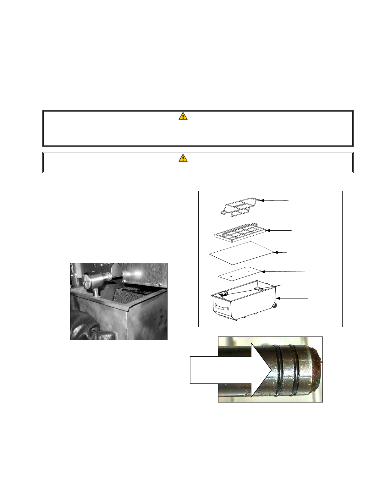
BIELA14-T SERIES GEN III LOV™ ELECTRIC FRYER
CHAPTER 5: FILTRATION MENU INSTRUCTIONS
5.1 Introduction
The FootPrint Pro filtration system allows the oil in one frypot to be safely and efficiently filtered while the other
frypots in a battery remain in operation.
Section 5.2 covers preparation of the filter system for use. Operation of the system is covered in Section 5.3.
WARNING
The on-site supervisor is responsible for ensuring that operators are made aware of the inherent hazards of
operating a hot oil filtering system, particularly the aspects of oil filtration, draining and cleaning
procedures.
WARNING
The filter pad or paper MUST be replaced daily.
5.2 Preparing the Filter for Use
1. Pull the filter pan out from the cabinet slightly
and wait until the dripping stops before
completely removing the pan (shown below).
Remove the crumb tray, hold-down ring, filter
pad (or paper), and filter screen (See Figure 1).
Clean all metal parts with a solution of All
Purpose Concentrate and hot water then dry
thoroughly.
Crumb
Tray
Hold‐Down
Ring
Filter Pad or
Paper
Screen
Pre‐Filter Screen
Filter
Pan
Figure 1
2. Inspect the filter pan connection fitting to
ensure that both O-rings are in good condition
(See Figure 2). Ensure the pre-filter screen is
installed, clean and tight.
Inspect the filter
connection fitting
O-rings.
3. Then in reverse order, place the metal filter screen in the center of the bottom of the pan, then lay a filter pad
over the screen, ensuring that the rough side of the pad is up. Make sure that the pad is in between the
embossed ridges of the filter pan. Then position the hold down ring on top of the pad. If using filter paper, lay a
sheet of filter paper over the top of the pan overlapping on all sides. Position the hold down ring over the filter
paper and lower the ring into the pan, allowing the paper to fold up and around the ring as it is pushed to the
bottom of the pan. Then sprinkle 1 packet (8-ounces) of filter powder over the filter paper.
Figure 2
5-1
Page 50
4. Reinstall the crumb tray at the front of the pan. (See Figure 1)
DO NOT USE FILTER POWDER WITH THE PAD!
5. Push the filter pan back into the fryer, positioning it under the fryer. Ensure “P” is not displayed in the top right
corner of any controller. The filtration system is now ready for use.
DANGER
Do not drain more than one frypot at a time into the built-in filtration unit to avoid overflow and spillage of
hot oil that may cause severe burns, slipping and falling.
DANGER
The crumb tray in fryers equipped with a filter system must be emptied into a fireproof container at the
end of frying operations each day. Some food particles can spontaneously combust if left soaking in certain
shortening material.
WARNING
Do not bang fry baskets or other utensils on the fryer’s joiner strip. The strip is present to seal the joint
between the fry vessels. Banging fry baskets on the strip to dislodge shortening will distort the strip,
adversely affecting its fit. It is designed for a tight fit and should only be removed for cleaning.
5.3 Filtration Menu
The filtration menu selections are used for filtering, draining, filling, disposing and cleaning the vats.
The filtration menu is listed below:
Auto Filtration page 5-2
Auto Demand Filtration page 5-3
Maintenance Filter page 5-5
Dispose Oil (Non-Bulk Systems) page 5-6
Dispose Oil (Bulk Systems) page 5-7
Drain Oil page 5-9
Fill Vat from Drain Pan page 5-10
Fill Vat from Bulk (Bulk Only) page 5-11
Oil Pan to Waste (Bulk Only) page 5-11
Deep Clean (Non-Bulk Systems) page 5-13
Deep Clean (Bulk Systems) page 5-15
5.3.1 Auto Filtration
Auto Filtration is a feature that, after a number of preset cook cycles or time, will automatically prompt to filter the
frypots. This function can also be performed on demand as well and is covered in the next section. Note:
Simultaneous filtering of multiple vats does not occur.
DISPLAY ACTION
FILTRATION REQUIRED - FILTER NOW?
OIL LEVEL TOO LOW
SKIM DEBRIS FROM VAT -
PRESS CONFIRM WHEN COMPLETE
1. Press the √ (check) button to start filtration. If the X button is
selected, filtering is cancelled, and the fryer resumes normal
operation. The filter button will turn yellow until the fryer is
filtered. The controller will prompt again soon to filter the oil.
This sequence repeats until a filter is completed.
2. Displayed if the oil level is too low. Press the √ (check) button to
acknowledge issue and return to idle cook mode. Check to see
if the JIB is low on oil. If JIB is not low and this continues to
occur, contact your FAS.
3. Skim the crumbs from the oil with a front to back motion,
removing as many crumbs as possible from each vat. This is
critical to optimizing usable oil life and quality in the oil. Press
the √ (check) button when complete.
5-2
Page 51
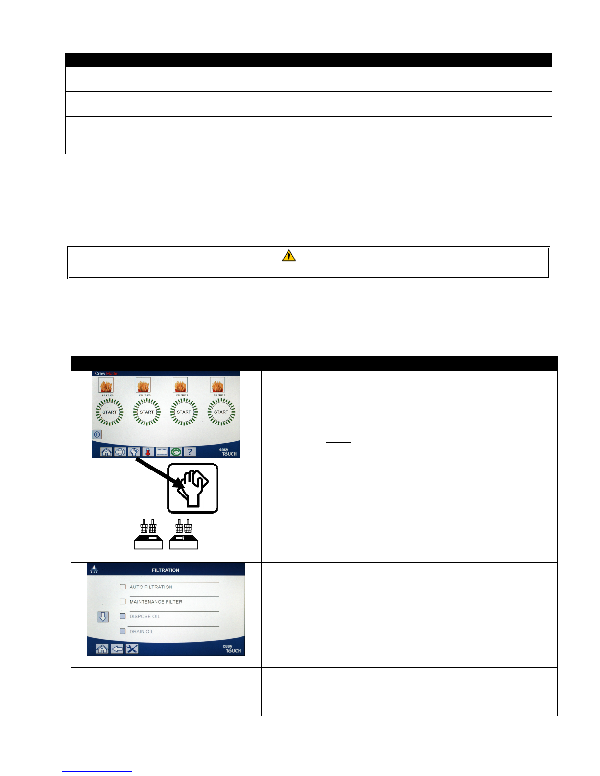
DISPLAY ACTION
INSERT PAN
DRAINING IN PROGRESS 5. No action required.
WASHING IN PROGRESS 6. No action required.
FILLING IN PROGRESS 7. No action required.
PREHEAT 8. No action required. Displayed until the fryer reaches setpoint.
START 9. Fryer is ready for use. Displayed once fryer reaches setpoint.
4. Push the filter pan fully into place. Displayed if the filter pan is
not fully engaged.
The complete filtering process takes roughly four minutes.
If during filtration the oil isn’t completely returned the system will proceed to an incomplete filtration function.
See section 7.3.1.
NOTE: If during filtration the filter pan is removed, the filtration process stops and resumes once pan is reseated
into place.
DANGER
Keep all items out of drains. Closing actuators may cause damage or injury.
5.3.2 Auto Demand Filtration
Auto demand filtration is used to manually start an auto filtration. Note: Simultaneous filtering of multiple vats does
not occur.
DISPLAY ACTION
AUTO FILTRATION?
1. The fryer MUST be at setpoint temperature. Press the filtration
menu button.
2. Select LEFT VAT or RIGHT VAT for split vats.
3. Select AUTO FILTRATION.
4. Press the √ (check) button to start filtration. If the X button is
selected, filtering is cancelled and the fryer resumes normal
operation.
5-3
Page 52
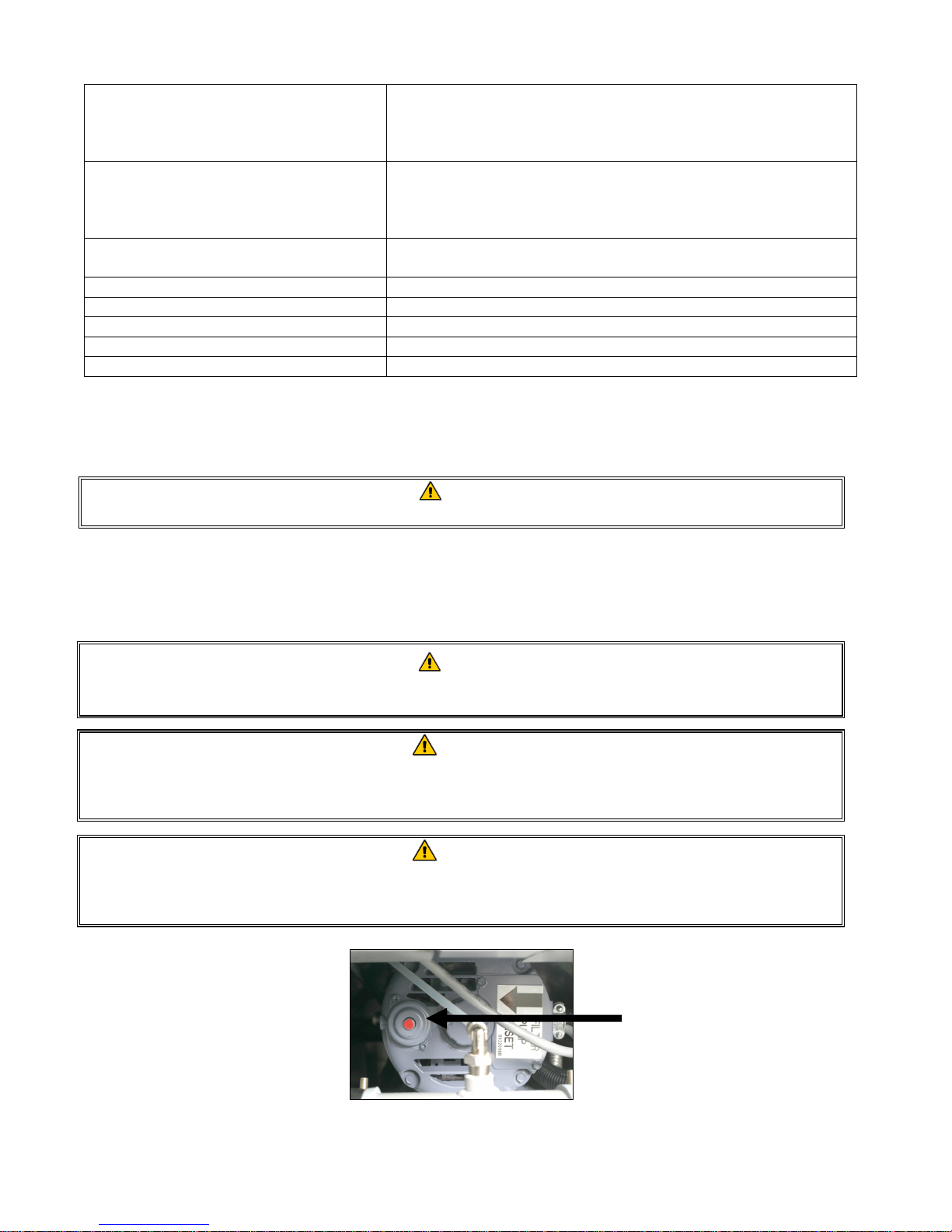
5. Displayed if the oil level is too low. Press the √ (check) button to
OIL LEVEL TOO LOW
acknowledge issue and return to idle cook mode. Check to see
if the JIB is low on oil. If JIB is not low and this continues to
occur, contact your FAS.
6. Skim the crumbs from the oil with a front to back motion,
SKIM DEBRIS FROM VAT -
PRESS CONFIRM WHEN COMPLETE
removing as many crumbs as possible from each vat. This is
critical to optimizing usable oil life and quality of the oil. Press
the √ (check) button when complete.
INSERT PAN
7. Push the filter pan fully into place. Displayed if the filter pan is
not fully engaged.
DRAINING IN PROGRESS 8. No action required as oil drains into filter pan.
WASHING IN PROGRESS 9. No action required as debris is flushed from the vat.
FILLING IN PROGRESS 10. No action required as the vat refills.
PREHEAT 11. No action required as the fryer heats to setpoint.
START 12. Fryer is ready for use. Displayed once fryer reaches setpoint.
The complete filtering process takes roughly four minutes.
NOTE: If during filtration the filter pan is removed, the filtration process stops and resumes once pan is reseated
into place.
DANGER
Keep all items out of drains. Closing actuators may cause damage or injury.
Should the auto filtration procedure fail an error message is generated. Follow the instructions on the controller to
clear the error.
When FILTER BUSY is displayed the FIB board is waiting on another vat to be filtered or waiting on another issue to
clear. Press the √ (check) button and wait 15 minutes to see if problem is corrected. If not, call your local FAS.
DANGER
Do not drain more than one frypot at a time into the built-in filtration unit to avoid overflow and spillage of
hot oil that may cause severe burns, slipping and falling.
WARNING
The filter motor is equipped with a manual reset switch in case the filter motor overheats or an electrical
fault occurs. If this switch trips, turn off power to the filter system and allow the pump motor to cool 20
minutes before attempting to reset the switch (see photo on the following page).
WARNING
Use caution and wear appropriate safety equipment when resetting the filter motor reset switch. Resetting
the switch must be accomplished with care to avoid the possibility of a serious burn from careless
maneuvering around the drain tube and frypot.
Filter Motor Reset Switch
5-4
Page 53
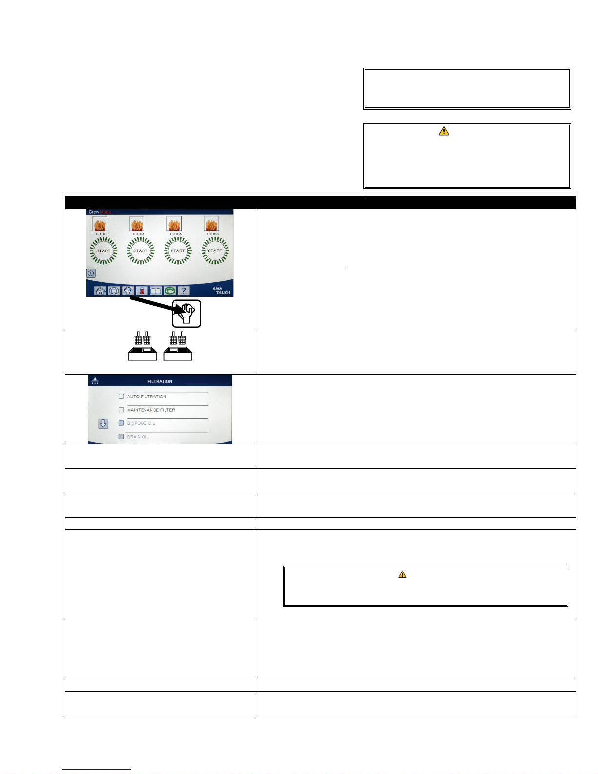
5.3.3 Maintenance or End of Day Filter
Ensure that the filter pad or paper is replaced daily to keep the
system operating correctly. For proper operation in high volume
or 24-hour stores, the filter pad or paper must be changed twice
a day.
The filter pad or paper must be replaced
daily.
If CLOSE DISPOSE VALVE is displayed, close the dispose valve.
Press the X button to exit.
Do not drain more than one frypot at a time
into the built-in filtration unit to avoid
overflow and spillage of hot oil that may
cause severe burns, slipping and falling.
DISPLAY ACTION
1. The fryer MUST be at setpoint temperature. Press the filtration menu
button.
2. Select LEFT VAT or RIGHT VAT for split vats.
NOTICE
WARNING
MAINTENANCE FILTRATION?
WEAR PROTECTIVE GLOVES – PRESS
CONFIRM WHEN COMPLETE
ENSURE OIL PAN AND COVER ARE IN
PLACE
DRAINING IN PROGRESS 7. No action required as oil drains into filter pan.
SCRUB INSIDE VAT AND BETWEEN HEATERS
– PRESS CONFIRM WHEN COMPLETE
CLEAN SENSORS –
PRESS CONFIRM WHEN COMPLETE
WASH VAT? 10. Press the √ (check) button.
WASHING IN PROGRESS
3. Select MAINTENANCE FILTER.
4. Press the √ (check) button to start filtration. If the X button is selected,
filtering is cancelled and the fryer resumes normal operation.
5. Press the √ (check) button once all personal protection equipment
including heat resistant gloves are in place.
6. Press the √ (check) button if the oil pan and cover are in place.
8. Scrub the vat. If electric clean in between the elements. Press the √
(check) button when complete.
DANGER
Keep all items out of drains. Closing actuators may cause
damage or injury.
9. (Gas Only) Clean the oil level sensor with a no scratch pad (see section
6.6.2 on page 6-4). (All Fryers) Clean around AIF and ATO sensors with
a screwdriver or similar object to remove any sediment from around
the sensors (see section 6.2.4 on page 6-1) and press the √ (check)
button when complete.
11. No action required while the return valve opens and the vat is flushed
with oil from the filter pan.
5-5
Page 54
DISPLAY ACTION
12. The filter pump shuts off. If the vat is clean of debris, press the X
WASH AGAIN?
RINSING IN PROGRESS
RINSE AGAIN?
POLISH? 15. Press the √ (check) button to continue.
POLISH IN PROGRESS
FILL VAT? 17. Press the √ (check) button to continue.
FILLING IN PROGRESS 18. No action required while the vat is refilled.
IS VAT FULL?
button to continue. If crumbs are still present, press the √ (check)
button and the filter pump runs again. This cycle repeats until the X
button is pressed.
13. No action required while the drain valve closes and the filter pump
refills the vat. The drain valve opens and rinses the vat.
14. If the vat is clean of debris, press the X button to continue. If an
additional rinse is desired, press the √ (check) button and the rinse
repeats until the X button is pressed.
16. No action required while the drain and return valves are open and oil
is pumped through the frypot for five minutes.
19. Press the X button to run the pump again if the oil level is below the
top oil level full line.* Press the √ (check) button once the oil level is at
the top oil level full line. If the vat oil level is not completely filled,
check the filter pan to see if most of the oil has returned. The pan
may have a small amount of oil.
Press the √ (check) button once no oil remains in the filter pan.
20. The controller switches off.
*NOTE: After a maintenance filtration it is normal to leave some oil in the pan and the level of oil may not
return to the level prior to starting maintenance filtration. Answering YES after two attempts at
refilling the vat enables auto top off to compensate for any loss of oil during filtration.
5.3.4 Dispose for Non-Bulk Oil Systems
This option is used to dispose of old oil into either a PMSDU or a METAL container.
When cooking oil is exhausted, dispose the oil into an appropriate container for transport to the waste oil container.
Frymaster recommends a McDonald’s Shortening Disposal Unit (PMSDU). Refer to the documentation furnished
with your disposal unit for specific operating instructions. NOTE: If using an MSDU built before January 2004 the
unit will not fit under the drain. If a shortening disposal unit is not available, allow the oil to cool to 100°F (38°C),
then drain the oil into a METAL container with a capacity of FOUR gallons (15 liters) or larger to prevent oil from
spilling.
DISPLAY ACTION
1. The fryer MUST be OFF.
2. Press the filtration menu button
3. Select LEFT VAT or RIGHT VAT for split vats.
5-6
Page 55
DISPLAY ACTION
4. Select DISPOSE OIL.
5. Press the √ (check) button to continue. If the X button is selected, the
user returns to the filtration menu.
DISPOSE OIL?
INSERT DISPOSAL UNIT
IS DISPOSE UNIT IN PLACE?
DISPOSING 8. No action is required while the vat disposes the oil.
IS VAT EMPTY? 9. Once the vat is empty, press the √ (check) button to continue.
CLEAN VAT COMPLETE?
MANUALLY FILL VAT
Allow oil to cool to 100°F (38°C) before draining into an
appropriate METAL container for disposal.
6. Remove the filter pan and insert the disposal unit.
When draining oil into a disposal unit, do not fill above the
maximum fill line located on the container.
7. Ensure the PMSDU or a METAL container with a capacity of FOUR
gallons (15 liters) or larger is in place. Press the √ (check) button to
continue.
When draining oil into an appropriate METAL container, make
sure the container will hold at least FOUR gallons (15 liters) or
more, otherwise hot liquid could overflow and cause injury.
10. Clean the vat with a scrub brush and when complete press the √
(check) button to continue.
11. Carefully pour oil into the vat until it reaches the low-level fill line in
the fryer. Press the √ (check) button once the vat is full.
DANGER
DANGER
DANGER
5.3.5 Dispose for Bulk Oil Systems
This option is used to dispose of old oil into a bulk waste oil
system such as RTI. Bulk oil systems use a pump to move
exhausted oil from the fryer to a holding tank. Additional
plumbing is used to connect the bulk oil systems to the fryers.
DISPLAY ACTION
12. The controller switches off.
WARNING
Ensure a filter pad is in place prior to draining
or disposing of oil. Failure to insert a filter
pad may result in clogged lines and/or pump.
1. The fryer MUST be OFF.
2. Press the filtration menu button
5-7
Page 56
DISPLAY ACTION
DISPOSE OIL?
BULK TANK FULL?
DRAINING IN PROGRESS 7. No action required as oil drains into filter pan.
VAT EMPTY? 8. Once the vat is empty, press the √ (check) button to continue.
CLEAN VAT COMPLETE?
OPEN DISPOSE VALVE
3. Select LEFT VAT or RIGHT VAT for split vats.
4. Select DISPOSE OIL.
5. Press the √ (check) button to continue. If the X button is selected, the
user returns to the filtration menu.
6. This message is only displayed if the bull tank is full. Press the √
(check) button to acknowledge and call the bulk oil waste provider.
The display returns to OFF.
9. Clean the vat with a scrub brush and when complete press the √
(check) button to continue.
10. Open the left cabinet door and unlock the valve if necessary. Pull the
dispose valve completely forward to start disposal.
DISPOSING
REMOVE PAN
IS PAN EMPTY?
INSERT PAN 14. Insert the filter pan.
CLOSE DISPOSE VALVE
FILL VAT FROM BULK?
START FILLING?
PRESS AND HOLD
RELEASE BUTTON WHEN FULL 18. Release the button when the vat is filled to the lower fill line.
11. No action is required while the pump transfers the waste oil from the
pan to the bulk oil waste tanks for four (4) minutes.
12. Carefully pull the filter pan from the fryer.
DANGER
Open the filter pan slowly to avoid splashing of hot oil that
may cause severe burns, slipping and falling.
13. If the filter pan is empty press the √ (check) button. If the pan is not
empty, press the X button and return to step 11 after inserting the
filter pan.
15. Close the dispose valve by pushing the valve handle toward the rear of
the fryer until it stops. Relock the valve if required by your manager.
16. The vat is ready to be refilled with oil. Press the √ (check) button to
continue otherwise press the X button to exit to step 20.
17. Press and hold the button to fill the vat. The bulk oil refill pump uses a
momentary switch. It only pumps as long as the switch is depressed.
5-8
Page 57
DISPLAY ACTION
19. Press the √ (check) button to return to step 17 and continue filling.
CONTINUE FILLING?
Otherwise press the X button once the vat is full to exit and return to
OFF.
20. The controller switches off.
5.3.6 Drain Oil to Pan
The drain to pan function drains the oil from the vat to the filter pan.
DISPLAY ACTION
1. The fryer MUST be OFF.
2. Press the filtration menu button
3. Select LEFT VAT or RIGHT VAT for split vats.
4. Select DRAIN OIL.
5. Press the √ (check) button to continue. If the X button is selected, the
DRAIN OIL TO PAN?
controller goes to OFF. If no pan is detected, the controller displays
ENSURE OIL PAN AND COVER ARE IN PLACE until the pan is detected.
DRAINING IN PROGRESS 6. No action is required while the vat drains the oil into the filter pan.
IS VAT EMPTY? 7. Once the vat is empty, press the √ (check) button to continue.
FILL VAT FROM DRAIN PAN? 8. Press the √ (check) button to refill the vat, otherwise skip to step 10.
FILLING 9. No action is required while the vat is filling.
10. Press the X button to run the pump again if the oil level is below the
IS VAT FULL?
top oil level full line. Press the √ (check) button once the vat is full and
skip to step 15 to return to OFF.
11. Carefully pull the filter pan from the fryer.
REMOVE PAN
DANGER
Open the filter pan slowly to avoid splashing of hot oil that
may cause severe burns, slipping and falling.
12. NOTE: A small quantity of oil may remain in the pan after refilling. If
the filter pan is empty press the √ (check) button and skip to step 12.
IS PAN EMPTY?
If the pan is not empty, press the X button and return to FILL VAT
FROM DRAIN PAN? in step 7. If the pan is not empty and the fryer is
using a bulk oil system, press the X button and continue to step 13.
INSERT PAN
PAN TO WASTE?
13. Insert the filter pan and skip to step 14 to return to OFF.
14. Press the √ (check) button to dispose of the oil to the bulk oil waste
tanks. Skip to section 5.3.10 OIL PAN TO WASTE step 6.
15. The controller switches off.
5-9
Page 58
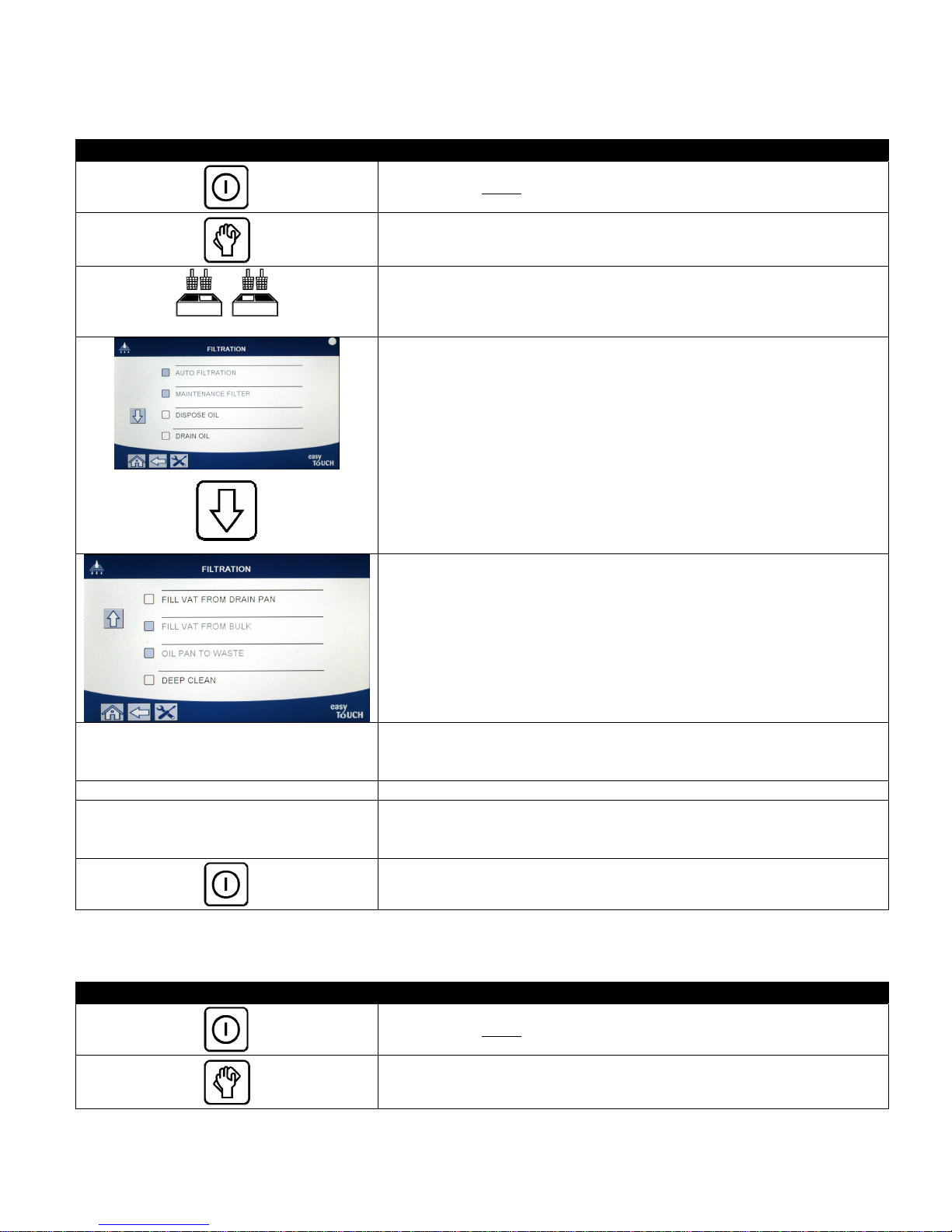
5.3.7 Fill Vat from Drain (Filter) Pan
The drain to pan function drains the oil from the vat to the filter pan.
DISPLAY ACTION
1. The fryer MUST be OFF.
2. Press the filtration menu button
FILL VAT FROM DRAIN PAN?
FILLING 7. No action is required while the vat is filling.
IS VAT FULL?
3. Select LEFT VAT or RIGHT VAT for split vats.
4. Press the down arrow.
5. Select FILL VAT FROM DRAIN PAN.
6. Press the √ (check) button to continue. If the X button is selected, the
controller goes to OFF. If no pan is detected, the controller displays
INSERT PAN until the pan is detected.
8. Press the X button to run the pump again if the oil level is below the
top oil level full line. Press the √ (check) button once the vat is full and
to return to OFF.
5.3.8 Fill Vat from Bulk
The drain to pan function drains the oil from the vat to the filter pan.
DISPLAY ACTION
9. The controller switches off.
1. The fryer MUST be OFF.
2. Press the filtration menu button
5-10
Page 59
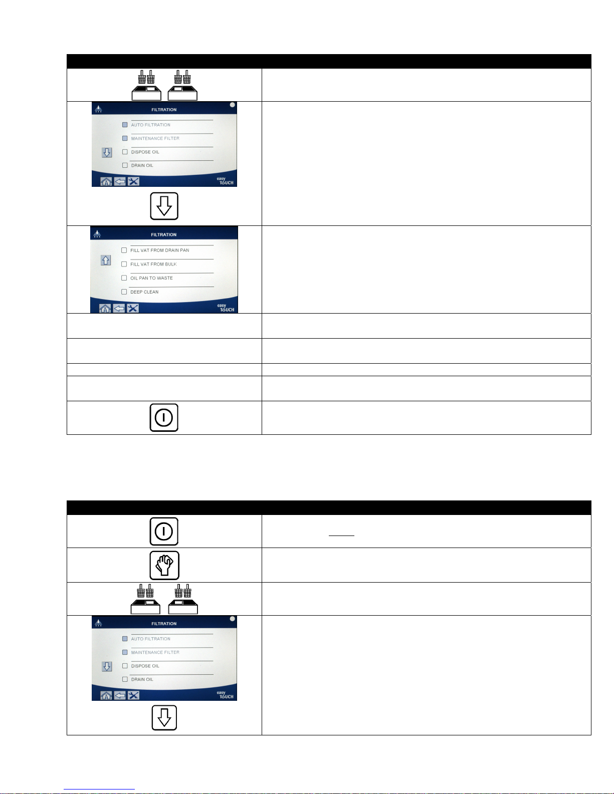
DISPLAY ACTION
3. Select LEFT VAT or RIGHT VAT for split vats.
4. Press the down arrow.
5. Select FILL VAT FROM BULK.
FILL VAT FROM BULK?
START FILLING?
PRESS AND HOLD
6. Press the √ (check) button to continue. If the X button is selected, the
controller goes to OFF.
7. Press and hold the button to fill the vat. The bulk oil refill pump uses a
momentary switch. It only pumps as long as the switch is depressed.
RELEASE BUTTON WHEN FULL 8. Release the button when the vat is filled to the lower fill line.
CONTINUE FILLING?
9. Press the √ (check) button to continue filling. Otherwise press the X
button once the vat is full to exit and return to OFF.
10. The controller switches off.
5.3.9 Oil Pan to Waste
Pan to waste selection is an option that allows bulk oil systems to pump excess oil in the pan to the bulk oil waste
tanks without draining the existing oil in the vat.
DISPLAY ACTION
1. The fryer MUST be OFF.
2. Press the filtration menu button
3. Select LEFT VAT or RIGHT VAT for split vats.
4. Press the down arrow.
5-11
Page 60
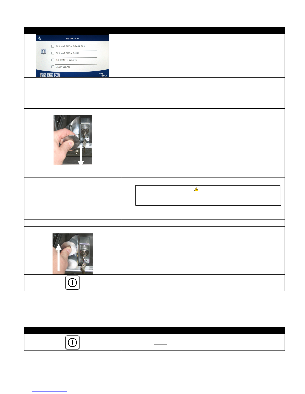
DISPLAY ACTION
5. Select OIL PAN TO WASTE.
6. Press the √ (check) button to continue. If the X button is selected, the
OIL PAN TO WASTE?
user returns to the filtration menu. If no pan is detected, the controller
displays INSERT PAN until the pan is detected.
BULK TANK FULL?
7. Press the √ (check) button to acknowledge and call the bulk oil waste
provider. The display returns to OFF.
OPEN DISPOSE VALVE
8. Open the left cabinet door and unlock the valve if necessary. Pull the
dispose valve completely forward to start disposal.
DISPOSING
REMOVE PAN
IS PAN EMPTY?
INSERT PAN
9. No action is required while the pump transfers the waste oil from the
pan to the bulk oil waste tanks for four (4) minutes.
10. Carefully pull the filter pan from the fryer.
DANGER
Open the filter pan slowly to avoid splashing of hot oil that
may cause severe burns, slipping and falling.
11. If the filter pan is empty press the √ (check) button. If the pan is not
empty, press the X button and return to step 9.
12. Insert the filter pan.
CLOSE DISPOSE VALVE
13. Close the dispose valve by pushing the valve handle toward the rear of
the fryer until it stops. Relock the valve if required by your manager.
14. The controller switches off.
5.3.10 Deep Clean (Boil-Out) for Non-Bulk Oil Systems
The deep clean mode is used to remove carbonized oil from the frypot.
NOTE: Refer to Kay Chemical “Fryer Deep Clean Procedure” instructions to clean the LOV™ fryer.
DISPLAY ACTION
1. The fryer MUST be OFF.
5-12
Page 61
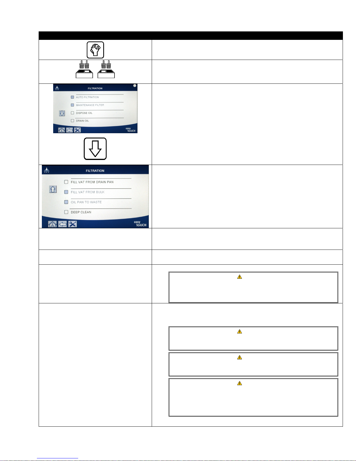
DISPLAY ACTION
2. Press the filtration menu button
DEEP CLEAN?
IS VAT OIL REMOVED?
INSERT DISPOSAL UNIT
IS DISPOSE UNIT IN PLACE?
3. Select LEFT VAT or RIGHT VAT for split vats.
4. Press the down arrow.
5. Select DEEP CLEAN.
6. Press the √ (check) button to continue. If the X button is selected, the
user returns to the filtration menu. If no pan is detected, the controller
displays INSERT PAN until the pan is detected.
7. Press the X button if oil is in the vat. Press the √ (check) button if the
vat is empty and skip to step 12.
8. Remove the filter pan and insert the disposal unit.
DANGER
Ensure a PMSDU (McDonald’s Shortening Disposal Unit) or
suitable metal container is in place under the drain with a
capacity of FOUR (4) gallons (15 liters) or more.
9. Ensure the PMSDU or a METAL container with a capacity of FOUR
gallons (15 liters) or larger is in place. Press the √ (check) button to
continue.
DANGER
Allow oil to cool to 100°F (38°C) before draining into an
appropriate METAL container for disposal.
DANGER
When draining oil into a disposal unit, do not fill above the
maximum fill line located on the container.
DANGER
When draining oil into an appropriate PMSDU or METAL
container, make sure the container will hold at least FOUR
gallons (15 liters) or more. Otherwise oil could overflow and
can cause injury.
5-13
Page 62
DISPLAY ACTION
DRAINING IN PROGRESS
IS VAT EMPTY? 11. Once the vat is empty, press the √ (check) button to continue.
SOLUTION ADDED?
DEEP CLEANING
CLEAN DONE
IS SOLUTION REMOVED?
SCRUB VAT COMPLETE? 16. Press the √ (check) button once the vat is scrubbed.
DRAINING IN PROGRESS
RINSE COMPLETE?
REMOVE PAN
VAT AND PAN DRY?
INSERT PAN
MANUALLY FILL VAT
10. No action is required while the vat drains the oil into the disposal
container.
12. Fill the vat to be cleaned with water and cleaning solution mix. Press
the √ (check) button to start the cleaning procedure. Refer to the
Deep Clean maintenance requirement card and Kay Chemical
provided instructions “Fryer Deep Clean Procedure” for McDonald’s
deep clean (boil-out) procedure.
13. Scrub the vat and then let the solution soak while the vat heats to 195°
F (91° C) for one hour.
14. After one hour, the heater shuts off. Press the √ (check)
button to silence the alarm.
15. Remove the filter pan and remove crumb basket, hold-down ring, filter
pad and screen. Replace empty filter pan in fryer. Refer to Kay
Chemical provided instructions “Fryer Deep Clean Procedure” for
instructions on how to remove the cleaning solution.
Press the √ (check) button once the cleaning solution is removed.
Allow deep-clean (boil-out) solution to cool to 100°F (38°C)
before disposal, otherwise hot liquid can cause injury.
17. No action is required while the vat drains the small amount of residual
solution left in the vat.
18. Rinse excess solution from vat. Press the √ (check) button when the
vat is completely rinsed.
19. Remove the filter pan and dump the contents of the filter pan. Rinse
the pan of any residual solution.
20. Ensure the vat and filter pan are completely dry.
Ensure that the frypot and filter pan are completely dry and
free of water before filling with oil. Failure to do so will cause
splattering of hot liquid when the oil is heated to cooking
temperature.
21. Reinstall screen, filter pad, hold down ring and crumb basket
removed in step 15. Insert the filter pan.
22. Carefully pour oil into the vat until it reaches the low-level fill line in
the fryer. Press the √ (check) button once the vat is full.
DANGER
DANGER
23. The controller switches off.
5-14
Page 63
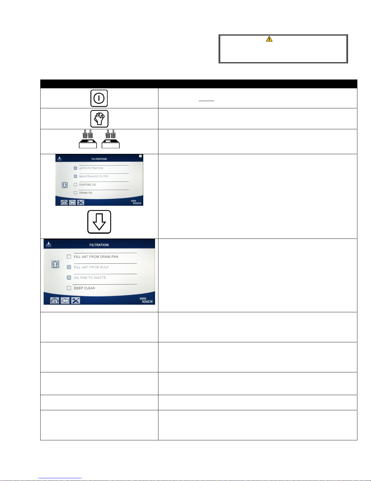
5.3.11 Deep Clean (Boil-Out) for Bulk Oil Systems
The deep clean mode is used to remove carbonized oil from
the frypot.
NOTE: Refer to Kay Chemical “Fryer Deep Clean
Procedure” instructions to clean the LOV™ fryer.
Ensure a filter pad is in place prior to draining
or disposing of oil. Failure to insert a filter pad
may result in clogged lines and/or pumps.
DISPLAY ACTION
1. The fryer MUST be OFF.
2. Press the filtration menu button
WARNING
DEEP CLEAN?
BULK TANK FULL?
IS VAT OIL REMOVED?
DRAINING IN PROGRESS
VAT EMPTY?
3. Select LEFT VAT or RIGHT VAT for split vats.
4. Press the down arrow.
5. Select DEEP CLEAN.
6. Press the √ (check) button to continue. If the X button is selected, the
user returns to the filtration menu. If no pan is detected, the controller
displays INSERT PAN until the pan is detected.
7. This message is only displayed if the bull tank is full. Press the √
(check) button to acknowledge and call the bulk oil waste provider.
The display returns to OFF.
8. Press the X button if oil is in the vat. Press the √ (check) button if the
vat is empty and skip to step 17.
9. No action required as oil drains into filter pan.
10. Once the vat is empty, press the √ (check) button to continue.
5-15
Page 64
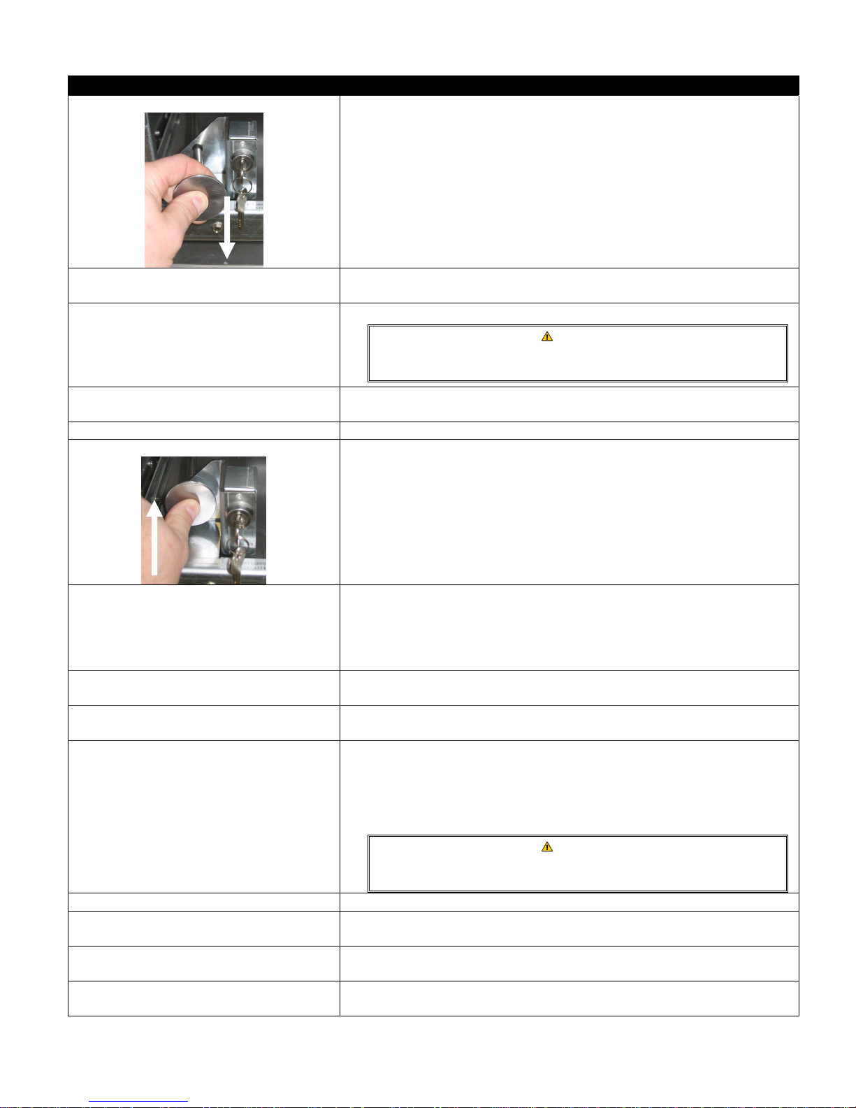
DISPLAY ACTION
OPEN DISPOSE VALVE
11. Open the left cabinet door and unlock the valve if necessary. Pull the
dispose valve completely forward to start disposal.
DISPOSING
REMOVE PAN
IS PAN EMPTY?
12. No action is required while the pump transfers the waste oil from the
pan to the bulk oil waste tanks for four (4) minutes.
13. Carefully pull the filter pan from the fryer.
DANGER
Open the filter pan slowly to avoid splashing of hot oil that may
cause severe burns, slipping and falling.
14. If the filter pan is empty press the √ (check) button. If the pan is not
empty, press the X button and return to step 9.
INSERT PAN 15. Insert the filter pan.
CLOSE DISPOSE VALVE
16. Close the dispose valve by pushing the valve handle toward the rear of
the fryer until it stops. Relock the valve if required by your manager.
17. Fill the vat to be cleaned with water and cleaning solution mix. Press
the √ (check) button to start the cleaning procedure. Refer to the
SOLUTION ADDED?
Deep Clean maintenance requirement card and Kay Chemical
provided instructions “Fryer Deep Clean Procedure” for McDonald’s
deep clean (boil-out) procedure.
DEEP CLEANING
CLEAN DONE
18. Scrub the vat and then let the solution soak while the vat heats to 195°
F (91° C) for one hour.
19. After one hour, the heater shuts off. Press the √ (check)
button to silence the alarm.
20. Remove the filter pan and remove crumb basket, hold-down ring, filter
pad and screen. Replace empty filter pan in fryer. Refer to Kay
Chemical provided instructions “Fryer Deep Clean Procedure” for
instructions on how to remove the cleaning solution.
IS SOLUTION REMOVED?
Press the √ (check) button once the cleaning solution is removed.
DANGER
Allow deep-clean (boil-out) solution to cool to 100°F (38°C)
before disposal, otherwise hot liquid can cause injury.
SCRUB VAT COMPLETE? 21. Press the √ (check) button once the vat is scrubbed.
DRAINING IN PROGRESS
RINSE COMPLETE?
REMOVE PAN
22. No action is required while the vat drains the small amount of residual
solution left in the vat.
23. Rinse excess solution from vat. Press the √ (check) button when the
vat is completely rinsed.
24. Remove the filter pan and dump the contents of the filter pan. Rinse
the pan of any residual solution.
5-16
Page 65
DISPLAY ACTION
25. Ensure the vat and filter pan are completely dry.
VAT AND PAN DRY?
INSERT PAN
FILL VAT FROM BULK?
START FILLING?
PRESS AND HOLD
RELEASE BUTTON WHEN FULL
CONTINUE FILLING?
Ensure that the frypot and filter pan are completely dry and
free of water before filling with oil. Failure to do so will cause
splattering of hot liquid when the oil is heated to cooking
temperature.
26. Reinstall screen, filter pad, hold down ring and crumb basket
removed in step 15. Insert the filter pan.
27. Press the √ (check) button to continue. If the X button is selected, the
user returns to the filtration menu.
28. Press and hold the button to fill the vat. The bulk oil refill pump uses a
momentary switch. It only pumps as long as the switch is depressed.
29. Release the button when the vat is filled to the lower fill line.
30. Press the √ (check) button to continue filling. Otherwise press the X
button once the vat is full to exit and return to OFF.
31. The controller switches off.
DANGER
5-17
Page 66
BIELA14-T SERIES GEN III LOV™ ELECTRIC FRYER
CHAPTER 6: PREVENTATIVE MAINTENANCE
6.1 Fryer Preventive Maintenance Checks and Service
DANGER
The crumb tray in fryers equipped with a filter system must be emptied into a fireproof container at the
end of frying operations each day. Some food particles can spontaneously combust if left soaking in certain
shortening material.
DANGER
Never attempt to clean the fryer during the frying process or when the frypot is filled with hot oil. If water
comes in contact with oil heated to frying temperature, it will cause spattering of the oil, which can result in
severe burns to nearby personnel.
WARNING
Use McDonald’s All-Purpose Concentrate. Read the directions for use and precautionary statements before
use. Particular attention must be paid to the concentration of cleaner and the length of time the cleaner
remains on the food contact surfaces.
6.2 DAILY CHECKS AND SERVICE
6.2.1 Inspect Fryer and Accessories for Damage
Look for loose or frayed wires and cords, leaks, foreign material in frypot or inside cabinet, and any other
indications that the fryer and accessories are not ready and safe for operation.
6.2.2 Clean Inside and Outside of the Fryer Cabinet – Daily
Clean inside the fryer cabinet with a dry, clean cloth. Wipe all accessible metal surfaces and components to remove
accumulated oil and dust.
Clean the outside of the fryer cabinet with a clean, damp cloth soaked with McDonald’s All-Purpose Concentrate.
Wipe with a clean, damp cloth.
6.2.3 Clean the Built-In Filtration System - Daily
Never operate the filter system without oil in the system.
Never use the filter pan to transport old oil to the disposal area.
Never drain water into the filter pan. Water will damage the filter pump.
There are no periodic preventive maintenance checks and services required for your FootPrint Pro Filtration System
other than daily cleaning of the filter pan with a solution of hot water and McDonald’s All-Purpose Concentrate.
If you notice that the systems is pumping slowly or not at all, verify that the filter pan screen is on the bottom of the
filter pan, with the pad on top of the screen. Verify that the two O-ring(s) on the fitting at the right front of the filter
pan are present and in good condition.
WARNING
WARNING
WARNING
6–1
Page 67
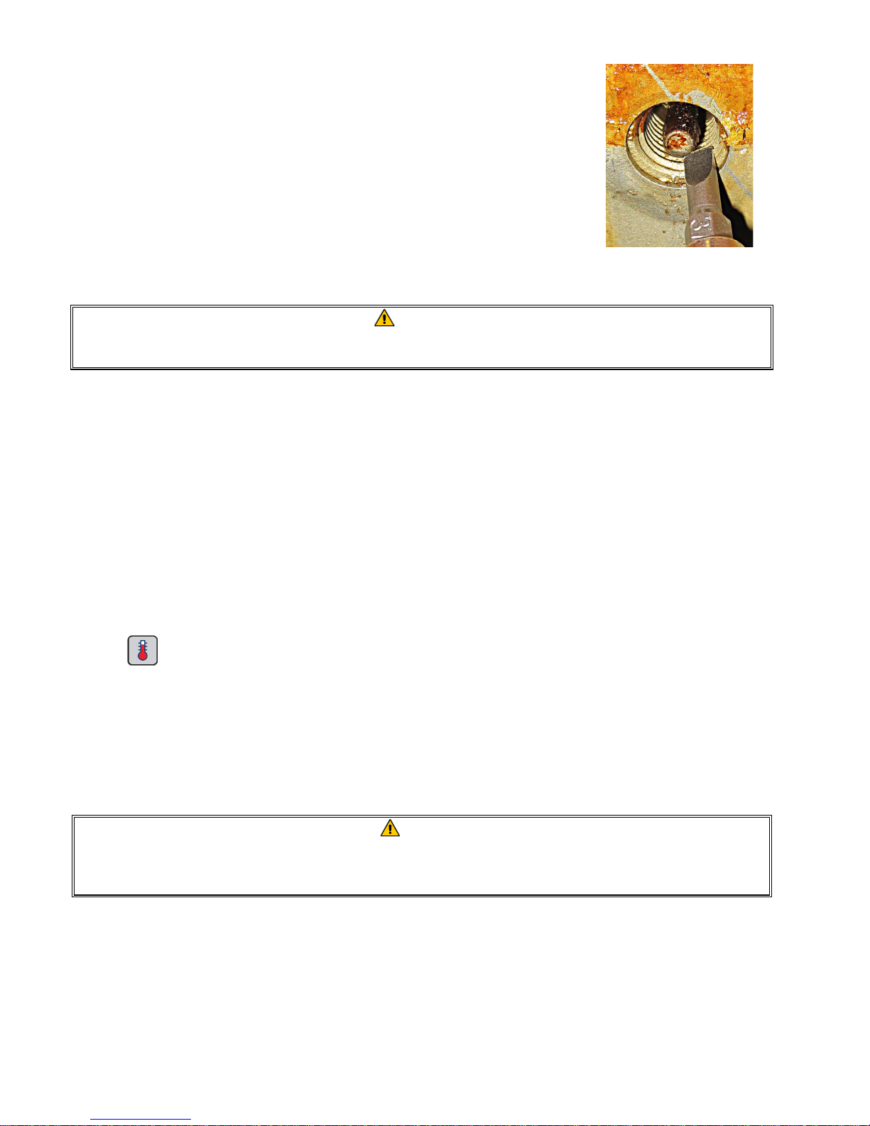
6.2.4 Clean around AIF and ATO sensors
1. Clean the sediment from around the AIF and ATO sensors during maintenance
filtration when the oil is drained from the frypot.
2. Use a screwdriver or other similar object which allows access around the probe
(see photo right). Use caution to ensure that the probe is not damaged.
3. Return the oil once the maintenance filtration is complete.
6.3 WEEKLY CHECKS AND SERVICE
6.3.1 Clean Behind Fryers
Clean behind fryers in accordance with the procedure detailed in maintenance requirement card.
WARNING
To ensure the safe and efficient operation of the fryer and hood, the electrical plug for the 120-volt line,
which powers the hood, must be fully engaged and locked in its pin and sleeve socket.
6.3.2 Clean Filter Pan, Detachable Parts and Accessories
Wipe all detachable parts and accessories with a clean, dry cloth. Use a clean cloth saturated with a solution of
McDonald’s All-Purpose Concentrate to remove accumulated carbonized oil on detachable parts and accessories.
Rinse the parts and accessories thoroughly with clean water and wipe dry before reinstalling. DO NOT use steel
wool or abrasive pads to clean these parts. The scratches that result from such scrubbing make subsequent
cleanings more difficult.
6.4 BI-WEEKLY CHECKS AND SERVICE
6.4.1 Check M4000 Controller Set Point Accuracy
1. Insert a good-grade thermometer or pyrometer probe into the oil, with the end touching the fryer temperaturesensing probe.
2. When the controller displays “START” (indicating that the frypot contents are within the cooking range), press
the
button once to display the temperature and setpoint of the oil as sensed by the temperature probe.
3 Note the temperature on the thermometer or pyrometer. Actual temperature and pyrometer readings should
be within ± 5ºF (3ºC) of each other after allowing the heat to cycle on and off three (3) times. If the temperature is
still out of tolerance, contact a Factory Authorized Servicer for assistance.
6.5 QUARTERLY CHECKS AND SERVICE
6.5.1 Clean the Frypot and Heating Elements
DANGER
Never operate the appliance with an empty frypot. The frypot must be filled to the fill line with water or
cooking oil before energizing the elements. Failure to do so will result in irreparable damage to the
elements and may cause a fire.
6.5.2 Replace the O-rings
Refer to McDonald’s MRC cards for specific details on replacing the O-rings on the filter connection.
6–2
Page 68
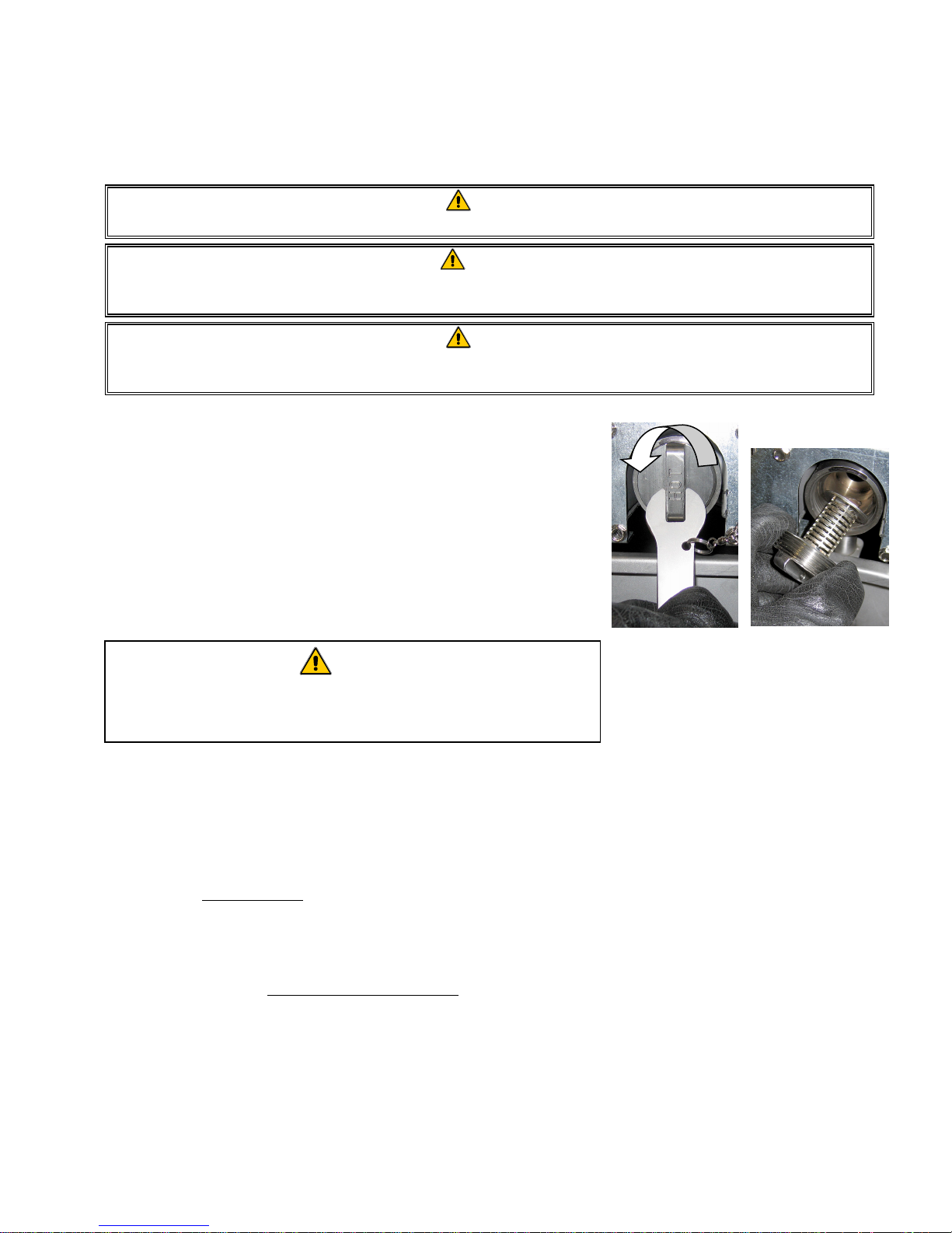
6.5.3 Deep Clean (Boiling Out) the Frypot
After the fryer has been in use for a period of time, a hard film of caramelized cooking oil will form on the inside of
the frypot. This film should be periodically removed by following the deep-clean (boil-out) procedure contained in
Kay Chemical “Fryer Deep Clean Procedure” instructions. Refer to pages 5-15 through 5-20 for specific details on setting
up the controller for deep clean (boil-out) operation.
DANGER
Allow oil to cool to 100ºF (38ºC) or lower before draining to an appropriate container for disposal.
WARNING
Never leave the fryer unattended during this process. If the solution overflows, press the ON/OFF switch to
the OFF position immediately.
DANGER
Ensure that the frypot is completely free of water before filling with oil. When the oil is heated to cooking
temperature, water in the frypot will cause splattering.
6.5.4 Pre-filter Maintenance
The pre-filter requires regular maintenance. Every 90 days, or more
frequently if the flow of oil slows, remove the cap and clean the attached
screen.
1. Wearing protective gloves use the supplied wrench to remove the cap
from the pre-filter (Figure 1).
2. Use a small brush to clear debris from the attached screen (Figure 2).
3. Clean under a water tap and thoroughly dry.
4. Return the cap to the pre-filter housing and tighten.
WARNING
DO NOT remove the pre-filter cap when a filter cycle is under way. DO
NOT operate the filter system with the cap removed. Wear protective
gloves when handling the cap. The metal and the exposed oil are hot.
Figure 1
Figure 2
6.6 Annual/Periodic System Inspection
This appliance should be inspected and adjusted periodically by qualified service personnel as
part of a regular kitchen maintenance program.
Frymaster recommends that a Factory Authorized Servicer inspect this appliance at least
annually as follows:
6.6.1 Fryer
● Inspect the cabinet inside and out, front and rear for excess oil.
● Verify that the heating element wires are in good condition and that leads have no visible fraying or insulation
damage and that they are free of oil.
● Verify that heating elements are in good condition with no carbon/caramelized oil build-up. Inspect the
elements for signs of extensive dry-firing.
● Verify that the tilt mechanism is working properly when lifting and lowering elements and that the element
wires are not binding and/or chafing.
● Verify the heating-element amp-draw is within the allowed range as indicated on the appliance’s rating plate.
6-3
Page 69

●
Verify that the temperature and high-limit probes are properly connected, tightened and functioning properly,
and that mounting hardware and probe guards are present and properly installed.
● Verify that component box and contactor box components (i.e. computer/controller, relays, interface boards,
transformers, contactors, etc.) are in good condition and free from oil and other debris.
● Verify that component box and contactor box wiring connections are tight and that wiring is in good condition.
● Verify that all safety features (i.e. contactor shields, reset switches, etc.) are present and functioning properly.
● Verify that the frypot is in good condition and free of leaks and that the frypot insulation is in serviceable
condition.
● Verify that all wiring harnesses and connections are tight and in good condition.
6.6.2 Built-In Filtration System
● Inspect all oil-return and drain lines for leaks and verify that all connections are tight.
● Inspect the filter pan for leaks and cleanliness. If there is a large accumulation of crumbs in the crumb basket,
advise the owner/operator that the crumb basket should be emptied into a fireproof container and cleaned
daily.
● Verify that all O-rings and seals are present and in good condition. Replace O-rings and seals if worn or
damaged.
● Check filtration system integrity as follows:
Verify that filter pan cover is present and properly installed.
With the filter pan empty, place each vat into fill vat from drain pan selection (see section 5.3.8 on page 5-
12), one at a time. Verify proper functioning of each oil return valve by activating the filter pump using the
fill vat from drain pan selection. Verify that the pump activates and that bubbles appear in the cooking oil
of the associated frypot.
Verify that the filter pan is properly prepared for filtering, then drain a frypot of oil heated to 350°F (177°C)
into the filter pan by using the drain to pan selection (see section 5.3.7 on page 5-11). Now using the fill vat
from pan drain pan selection (see section 5.3.8 on page 5-12), allow all oil to return to the frypot (indicated
by bubbles in the cooking oil). Press the check button when all oil is returned. The frypot should have
refilled in approximately 2 minutes and 30 seconds.
6–4
Page 70
BIELA14-T SERIES GEN III LOV™ ELECTRIC FRYER
CHAPTER 7: OPERATOR TROUBLESHOOTING
7.1 Introduction
This section provides an easy reference guide to some of the common problems that may occur during the
operation of this equipment. The troubleshooting guides that follow are intended to help correct, or at least
accurately diagnose, problems with this equipment. Although the chapter covers the most common problems
reported, you may encounter problems that are not covered. In such instances, the Frymaster Technical Services
staff will make every effort to help you identify and resolve the problem.
When troubleshooting a problem, always use a process of elimination starting with the simplest solution and
working through to the most complex. Never overlook the obvious – anyone can forget to plug in a cord or fail to
close a valve completely. Most importantly, always try to establish a clear idea of why a problem has occurred. Part
of any corrective action involves taking steps to ensure that it doesn’t happen again. If a controller malfunctions
because of a poor connection, check all other connections, too. If a fuse continues to blow, find out why. Always
keep in mind that failure of a small component may often be indicative of potential failure or incorrect functioning
of a more important component or system.
Before calling a service agent or the Frymaster HOTLINE (1-800-24-FRYER):
Verify that electrical cords are plugged in and that circuit breakers are on.
Have your fryer’s model and serial numbers ready to give to the technician assisting you.
DANGER
Hot oil will cause severe burns. Never attempt to move this appliance when filled with hot oil or to transfer
hot oil from one container to another.
DANGER
This equipment should be unplugged when servicing, except when electrical circuit tests are required. Use
extreme care when performing such tests.
This appliance may have more than one electrical power supply connection point. Disconnect all power
cords before servicing.
Inspection, testing, and repair of electrical components should be performed by an authorized service agent
only.
7-1
Page 71
7.2 Troubleshooting
7.2.1 Controller and Heating Problems
Problem
No Display on
Controller.
A. No power to fryer.
B. Failed controller or another component
Probable Causes Corrective Action
A filter error has occurred due to dirty or
clogged filter pad or paper, clogged pre-
M4000 displays IS
VAT FULL? YES NO
after a filtration.
filter, improperly installed filter pan
components, worn or missing O-rings, cold
oil or filter motor thermal tripped, failed
return valve or actuator, failed drain valve
or actuator or clogged filter pump.
Filter error has occurred, filter pad/paper
M4000 displays CHANGE
FILTER PAD?
clogged, 25-hour filter pad/paper change
prompt has occurred or change filter
pad/paper was ignored on a prior prompt.
A. Main power cord not plugged in.
Fryer does not heat.
B. Controller or other components have
failed.
Fryer heats until high-
limit trips with heat
Temperature probe or controller has failed. Call your FAS for assistance.
indicator ON.
Fryer heats until high-
limit trips without heat
Contactor or controller has failed Call your FAS for assistance.
indicator ON.
M4000 displays
MISCONFIGURED
Energy type in fryer setup is incorrect.
ENERGY TYPE
M4000 displays VAT ID
CONNECTOR NOT
Controller locator missing or disconnected.
CONNECTED
Controller locks up. Controller error.
7.2.2 Error Messages and Display Problems
Problem
M4000 display s E19
HEATING FAILURE.
Failed controller, failed transformer, failed
SIB board, open high-limit thermostat.
Probable Causes Corrective Action
M4000 display is in
wrong temperature
scale (Fahrenheit or
Incorrect display option programmed.
Celsius).
M4000 displays HOT-HI-
Frypot temperature is more than 410ºF
1.
(210ºC) or, in CE countries, 395ºF (202ºC).
A. Verify that the fryer is plugged in and
that the circuit breaker is not tripped.
B. Call your FAS for assistance.
Follow instructions on the screen to clear
the error. See section 5.2 for instructions
to change the filter; section 6.5.4 to clean
the pre-filter, or 5.3.2 to locate filter
motor overload. If problem persists, call
your FAS for assistance.
Change the filter pad/paper and ensure
the filter pan has been removed from
the fryer for a minimum of 30 seconds.
Do NOT ignore CHANGE FILTER
PAD/PAPER prompts.
A. Verify that both the main power cord
and 120V is fully seated in its
receptacle, locked into place and that
circuit breaker is not tripped
B. Call your FAS for assistance.
Ensure that the fryer is configured
properly for the correct energy type.
Ensure the 6-pin locator is connected to
rear of controller and it properly
grounded in control box.
Remove and restore power to the
controller. If problem persists, call your
FAS for assistance.
Call your FAS for assistance.
Toggle between F° to C° by entering
Manager settings, temperature and
toggling the temperature scale. Turn the
controller on to check temperature. If the
desired scale is not displayed, repeat.
Shut the fryer down immediately and call
your FAS for assistance.
7-2
Page 72
Problem
Probable Causes Corrective Action
M4000 displays HELP HI-
2 or HIGH LIMIT
FAILURE DISCONNECT
Failed high limit
POWER.
M4000 displays
TEMPERATURE PROBE
FAILURE.
Heating indicator is on,
but fryer is not heating.
M4000 displays
RECOVERY FAULT and
alarm sounds.
Problem with the temperature measuring
circuitry including the probe or damaged
controller wiring harness or connector.
Three phase power cord unplugged or
circuit breaker is tripped.
Recovery time exceeded maximum time
limit.
M4000 displays NO
MENU GROUP
AVAILABLE FOR
All menu groups have been deleted.
SELECTION
M4000 displays SERVICE
REQUIRED followed by
an error message.
An error has occurred which requires a
service technician.
7.3 Troubleshooting the Auto Filtration
Problem
Fryer filters after each
cook cycle.
Filter after setting incorrect.
Probable Causes Corrective Action
Shut the fryer down immediately and call
your FAS for assistance.
Shut the fryer down and call your FAS for
assistance.
Verify that both the main power cord and
120V is fully seated in its receptacle, locked
into place and that circuit breaker is not
tripped If the problem continues call your
FAS for assistance.
Clear error and silence the alarm by
pressing the √ button. Maximum recovery
time for electric is 1:40. If this error
continues call your FAS for assistance.
Create a new MENU group. Once a new
menu is created, add recipes to the group
(see section 4.10).
Press (2 NO) to continue cooking and call
your FAS for assistance. In some cases,
cooking may not be available.
Change or overwrite the filter after setting
by re-entering the filter after value in
Manager Settings, Filter Attributes in
section 4.8.
MAINTENANCE FILTER
won’t start.
M4000 display shows
FILTER BUSY.
Filter pump won’t start
or pump stops during
filtering.
Drain valve or return
valve stays open.
Temperature too low.
A. Another filtration cycle or filter pad
change is still in process.
B. Filter interface board has not cleared
checking system.
A. Power cord is not plugged in or circuit
breaker is tripped.
B. Pump motor has overheated causing
the thermal overload switch to trip.
C. Blockage in filter pump.
A. VIB board has failed.
B. Actuator has failed.
Ensure fryer is at setpoint before starting
MAINTENANCE FILTER.
A. Wait until the previous filtration
cycle ends to start another filtration
cycle. Change filter pad if prompted.
B. Wait 15 minutes and try again.
A. Verify that the power cord is fully
plugged in and the circuit breaker is
not tripped.
B. If the motor is too hot to touch for
more than a few seconds, the
thermal overload switch has
probably tripped. Allow the motor to
cool at least 45 minutes then press
the Pump Reset Switch (see page 5-
5).
C. Call your FAS for assistance.
Call your FAS for assistance.
7-3
Page 73

Problem
M4000 display shows
INSERT pan.
Auto filtration won’t
start.
Filter Pump runs, but
oil return is very slow.
Probable Causes Corrective Action
A. Filter pan is not fully set into fryer.
B. Missing filter pan magnet.
C. Defective filter pan switch.
A. Oil level too low.
B. Oil temperature is too low.
C. Filter Pan out.
D. Filtration in recipe settings is set to
OFF.
E. Filter relay has failed.
A. Improperly installed or prepared filter
pan components.
B. Pre-filter screen may be clogged.
A. Pull filter pan out and fully reinsert
into fryer. Ensure controller does
not display P.
B. Ensure the filter pan magnet is in
place and replace if missing.
C. If the filter pan magnet is fully
against the switch and controller
continues to display INSERT PAN,
switch is possibly defective.
A. Ensure oil level is at the top oil fill
line (at the top oil level sensor).
B. Ensure the oil temperature is at
setpoint.
C. Ensure controller does not display
P. Ensure the filter pan is fully
seated into fryer. Power cycle the
fryer.
D. Set filtration in recipes to ON.
E. Call your FAS for assistance.
A. Remove the oil from the filter pan
and replace the filter pad/paper,
ensuring that the filter screen is in
place under the pad/paper.
Verify, if using a pad, that the rough
side is facing up.
Verify that O-rings are present and in
good condition on filter pan
connection fitting.
B. Clean pre-filter (see section 6.5.4).
7-4
Page 74
7.3.1 Incomplete Filtration
Should the auto filtration procedure fail an error message is generated. Follow the instructions on the screen to return
the oil and clear the error.
DISPLAY ACTION
1. Press the √ (check) button if the vat is full to continue. The
IS VAT FULL?
controller returns to idle cook mode or
. Press X if vat is not
filled completely.
FILLING IN PROGRESS 2. No action required as the pump runs.
3. Press the √ (check) button if the vat is full to continue. The
IS VAT FULL?
controller returns to idle cook mode or . Press X if vat is not
filled completely.
FILLING IN PROGRESS 4. No action required as the pump runs.
5. Press the √ (check) button if the vat is full to continue. The
IS VAT FULL?
controller returns to idle cook mode or . Press X if vat is not
filled completely. If this is the sixth consecutive sequence of
incomplete filtration skip to step 10.
6. Press the √ (check) button to continue. Pressing X advances to
CHANGE FILTER PAD?
.
REMOVE PAN 7. Remove the filter pan.
8. Change the filter pad and ensure the filter pan has been pulled
forward, out of the cabinet for at least 30 seconds. Once the pan
CHANGE FILTER PAD
has been out for 30 seconds the controller returns to idle cook
mode. Ensure the pan is dry and assembled correctly. Push the
filter pan back into the fryer. Ensure “P” is not displayed on the
controller.
9. Press the √ (check) button if the vat is full to continue. The
IS VAT FULL?
controller returns to idle cook mode. Press X if vat is not full and
the controller advances to .
SERVICE REQUIRED
ERROR PUMP NOT FILLING
10. If a filtration error occurs six consecutive times, the return valve
closes. Press the √ (check) button to silence alarm and continue.
11. The system detects oil is not returning to the vat and service is
required. Call your FAS.
12. Press the X button to continue cooking if possible. Call your FAS to
SYSTEM ERROR FIXED?
repair and reset the fryer. The error will be re-displayed every 15
minutes until the issue is repaired. Auto filtration and auto top
off are disabled until the fryer is reset.
ENTER CODE 13. FAS tech enters tech code to reset fryer.
14. Press the √ (check) button to fill the vat from filter pan to
FILL VAT FROM DRAIN PAN?
continue. Follow prompts once the vat is full. Press X to skip
filling from drain pan.
REMOVE PAN 15. Remove the filter pan.
16. Press the √ (check) button if the filter pan is empty and continue
IS PAN EMPTY?
to next step. Press X to continue filling the vat. Follow the
prompts once the vat is full.
17. The controller switches off.
7-5
Page 75
7.3.2 Filter Busy
When FILTER BUSY is displayed the filter interface board is waiting on another vat to be filtered or waiting on
another function to finish. Wait 15 minutes to see if problem is corrected. If not, call your local FAS.
7.4 Troubleshooting Auto Top Off Issues
PROBLEM PROBABLE CAUSES CORRECTIVE ACTION
Frypots top off cold. Incorrect setpoint. Ensure setpoint is correct.
One vat doesn’t top off.
A. Filter error exists.
B. Service required error exists
C. Solenoid, pump, pin issue, RTD or ATO
A. Clear filter error properly. If problem
persists call your FAS for assistance.
B. Call your FAS for assistance.
C. Call your FAS for assistance.
issue.
A. Fryer temperature must be at
setpoint.
B. Ensure that the oil in the top off
reservoir is above 70°F (21°C).
C. Ensure the top off reservoir is not
out of oil. Replace top off reservoir
or fill from bulk and reset top off
system.
If problem persists call your FAS for
assistance.
D. Call your FAS for assistance.
E. Ensure the switch on the melting unit
is in the ON position.
Frypots won’t top off.
A. Fryer temperature too low.
B. Oil is too cold.
C. Yellow top off oil indicator illuminated
D. Service required error exists
E. Melting unit switch is off (only on solid
shortening units)
F. Blown fuse.
F. Check the fuse on the left of the ATO
box. If using a solid shortening
melting unit, check the fuse below
7.5 Troubleshooting Bulk Oil System Problems
the melting unit switch.
PROBLEM PROBABLE CAUSES CORRECTIVE ACTION
A. Power cycle fryer by disconnecting and
reconnecting 5-pin bulk oil control power
cord on rear of fryer.
Top off reservoir
won’t fill.
A. Incorrect setup procedure.
B. Another function is in process.
C. Dispose valve not completely closed.
D. Bulk oil tank is empty.
E. Solenoid, pump or switch issue.
B. If a filtration or any other filter menu
function is in process or FILTER NOW?
YES/NO, CONFIRM YES/NO, or SKIM VAT are
displayed, wait until the process is
complete and try again.
C. Ensure the dispose valve handle is pushed
fully closed.
D. Call your bulk oil provider.
E. Call you FAS for assistance.
Top off reservoir
or vat filling slow.
A. Pump or line issues beyond the scope
of operator troubleshooting.
A. Contact your bulk oil provider.
7-6
Page 76
PROBLEM PROBABLE CAUSES CORRECTIVE ACTION
A. Power cycle fryer by disconnecting and
Frypot won’t fill.
A. Incorrect setup procedure.
B. Dispose valve not completely closed.
C. Bulk oil tank is empty.
D. RTI pump issue.
reconnecting 5-pin bulk oil control power
cord on rear of fryer.
B. Ensure the dispose valve handle is pushed
fully closed.
C. Call your bulk oil provider.
D. Call you FAS for assistance.
7.6 Error Log Codes
See section 4.13.2.1 for instructions to access the Error Log.
Code ERROR MESSAGE EXPLANATION
E13 TEMPERATURE PROBE FAILURE TEMP Probe reading out of range
E16 HIGH LIMIT 1 EXCEEDED High limit temperature is past more than 410°F
(210°C), or in CE countries, 395°F (202°C)
E17 HIGH LIMIT 2 EXCEEDED High limit switch has opened.
E18 HIGH LIMIT PROBLEM
DISCONNECT POWER
Vat temperature exceeds 460°F (238°C) and the
high limit has failed to open. Immediately
disconnect power to the fryer and call service.
E19 HEATING FAILURE – XXX F or XXX C Heating Control latch circuit failed.
Heat Contactor failed to latch.
E25 HEATING FAILURE - BLOWER The air pressure switch(s) failed to close.
E27 HEATING FAILURE - PRESSURE SWITCH - CALL SERVICE The air pressure switch has failed closed.
E28 HEATING FAILURE – XXX F or XXX C The fryer has failed to ignite and has locked out
the ignition module.
E29 TOP OFF PROBE FAILURE - CALL SERVICE ATO RTD reading out of range
E32 DRAIN VALVE NOT OPEN - FILTRATION AND TOP OFF
DISABLED - CALL SERVICE
E33 DRAIN VALVE NOT CLOSED - FILTRATION AND TOP OFF
DISABLED - CALL SERVICE
E34 RETURN VALVE NOT OPEN - FILTRATION AND TOP OFF
DISABLED - CALL SERVICE
E35 RETURN VALVE NOT CLOSED - FILTRATION AND TOP
OFF DISABLED - CALL SERVICE
E36 VALVE INTERFACE BOARD FAILURE - FILTRATION AND
TOP OFF DISABLED - CALL SERVICE
E37 AUTOMATIC INTERMITTENT FILTRATION PROBE
Drain valve was trying to open and confirmation is
missing
Drain valve was trying to close and confirmation is
missing
Return valve was trying to open and confirmation
is missing
Return valve was trying to close and confirmation
is missing
Valve Interface Board connections lost or board
failure.
AIF RTD reading out of range.
FAILURE - FILTRATION DISABLED - CALL SERVICE
E39 CHANGE FILTER PAD 25 hour timer has expired or dirty filter logic has
activated.
E41 OIL IN PAN ERROR The system detects that oil may be present in the
filter pan.
E42 CLOGGED DRAIN (Gas) Vat did not empty during filtration
E43 OIL SENSOR FAILURE - CALL SERVICE Oil level sensor may have failed.
E44 RECOVERY FAULT Recovery time exceeded maximum time limit.
E45 RECOVERY FAULT – CALL SERVICE Recovery time exceeded maximum time limit for
two or more cycles.
E46 SYSTEM INTERFACE BOARD 1 MISSING - CALL SERVICE SIB board 1 connection lost or board failure.
E51 DUPLICATE BOARD ID - CALL SERVICE Two or more controllers have the same location
E52 USER INTERFACE CONTROLLER ERROR - CALL SERVICE The controller has an unknown error.
ID.
7-7
Page 77
Code ERROR MESSAGE EXPLANATION
E53 CAN BUS ERROR - CALL SERVICE Communications are lost between boards.
E54 USB ERROR USB connection lost during an update.
E55 SYSTEM INTERFACE BOARD 2 MISSING - CALL SERVICE SIB board 2 connection lost or board failure.
E61 MISCONFIGURED ENERGY TYPE The fryer is configured for the incorrect energy
type.
E62 VAT NOT HEATING – CHECK ENERGY SOURCE – XXXF
The vat is not heating properly.
OR XXXC
E63 RATE OF RISE Rate of rise error occurred during a recovery test.
E64 FILTRATION INTERFACE BOARD FAILURE - FILTRATION
AND TOP OFF DISABLED - CALL SERVICE
Filtration Interface Board connections lost or
board failure.
E65 CLEAN OIB SENSOR – XXX F OR XXX C - CALL SERVICE Gas -The oil is back sensor does not detect oil.
Clean oil sensor (see section 6.6.2).
E66 DRAIN VALVE OPEN – XXXF OR XXXC Drain valve is opened during cooking.
E67 SYSTEM INTERFACE BOARD NOT CONFIGURED - CALL
SERVICE
Controller is turned on when the SIB board is not
configured.
E68 OIB FUSE TRIPPED – CALL SERVICE The VIB board OIB fuse has tripped and didn’t
reset.
E69 RECIPES NOT AVAILABLE – CALL SERVICE The controller has not been programmed with
product recipes. Replace controller with factory
programmed controller.
E70 OQS TEMP HIGH Oil temperature is too high for a valid OQS
reading. Filter at a temperature between 300ºF
(149ºC) and 375ºF (191ºC).
E71 OQS TEMP LOW Oil temperature is too low for a valid OQS reading.
Filter at a temperature between 300ºF (149ºC) and
375ºF (191ºC).
E72 TPM RANGE LOW The TPM is too low for a valid OQS reading. This
may also be seen with fresh new oil. The incorrect
oil type may be selected in the setup menu. The
sensor may not be calibrated for the oil type. See
oil type chart in instruction document 8197316. If
issue continues contact a FAS.
E73 TPM RANGE HIGH The TPM reading is too high for a valid OQS
reading. Dispose the oil.
E74 OQS ERROR The OQS has an internal error. If issue continues
contact a FAS.
E75 OQS AIR ERROR The OQS is detecting air in the oil. Check the O-
rings and check/tighten prescreen filter to ensure
no air is entering the OQS sensor. If issue
continues contact a FAS.
E76 OQS ERROR The OQS sensor has a communication error. Check
connections to the OQS sensor. Power cycle the
entire fryer battery. If issue continues contact a
FAS.
7-8
Page 78
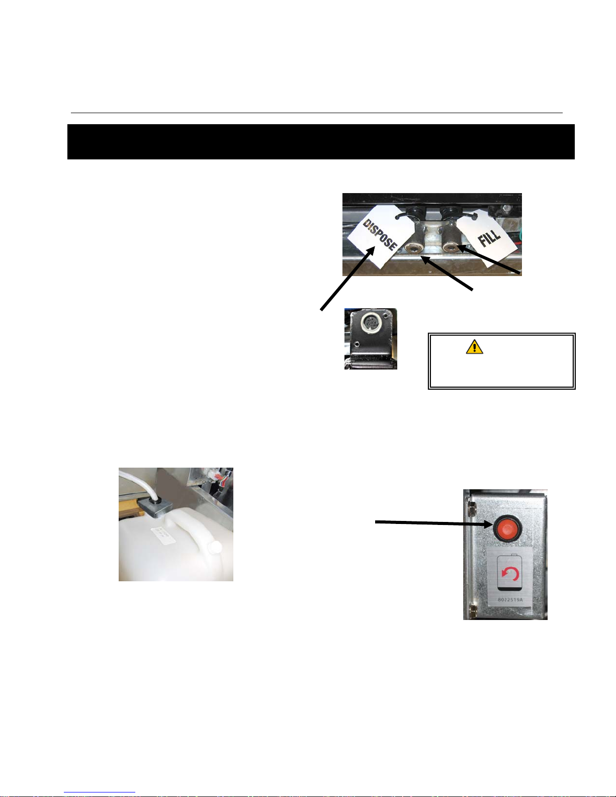
BIELA14-T SERIES GEN III LOV™ ELECTRIC FRYER
p
APPENDIX A: RTI (BULK OIL) INSTRUCTIONS
NOTE: The instructions in this manual for using a bulk oil system for filling and discarding oil are for an RTI
system. These instructions may not be applicable to other bulk oil systems.
C.1.1 Bulk Oil Systems
Bulk oil systems have large oil storage tanks,
typically located in the rear of the restaurant,
that are connected to a rear manifold on the
fryer. Waste oil is pumped from the fryer, via the
fitting located on the bottom, to the disposal
tanks and fresh oil is pumped from the tanks,
thru the fitting located on the top, to the fryer
(see Figure 1). Remove the plate exposing the
RTI connection and connect the RTI connection
to the fryer (see Figure 2).
It is necessary that the fryer system be
completely power cycled after changing oil
system type from JIB to Bulk.
The LOV™ fryers, equipped for use with bulk oil
systems, have an onboard fresh oil jug supplied
by RTI. Remove the cap and insert the standard
fitting into the jug with the metal cap resting on
the lip of the jug. The oil is pumped in and out of
the jug through the same fitting (see Figure 3).
Figure 1
Waste Oil
Connection
Fresh Oil
Connection
RTI wiring
connection
(behind
Dispose tag).
Figure 2
The momentary switch used to reset the top off reservoir low
indicator is also used to fill the jug in an RTI system. After pressing
the button to reset the top off system, pressing and holding the
momentary switch, located above the top off reservoir, allows the
operator to fill the jug from the bulk oil storage tank (see Figure 4).
To fill the jug, press and hold the top off reset button until the jug
is full, then release.*
NOTE: Do NOT overfill the jug.
For instructions on filling the vat
from bulk, see Section 5.3.9.
Do not add HOT or USED
oil to a to
WARNING
off reservoir.
Figure 3
* NOTE: It takes approximately twelve seconds from the time the top off reset button is pressed until the RTI pump
starts. It may take up to 20 seconds before the level in the top off reservoir begins to rise. Typically, it
takes approximately three minutes to fill the reservoir. It takes approximately one minute to fill a split vat
and two minutes to fill a full vat.
Figure 4
A–1
Page 79
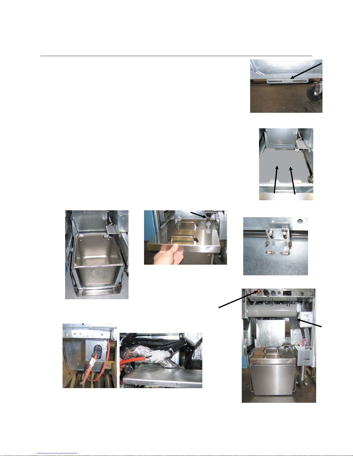
BIELA14-T SERIES GEN III LOV™ ELECTRIC FRYER
APPENDIX B: JIB Preparation with Solid Shortening Option
1. Open second or third door from the left of fryer and remove brace
in JIB cabinet.
2. Attach alignment bracket to bottom of ATO box brace with provided
nuts. See Figure 1.
3. Position melting unit in front of cabinet.
4. Slide the melting unit tabs into the alignment guide slots. See Figure
2.
5. With the melting unit inserted into the alignment guide bracket,
insert the inner oil reservoir pan into the tray. See Figure 3.
6. Place the melting unit lid on the unit and slide the oil pickup tube
nipple into the female suction receptacle. See Figure 4.
7. Use the provided screws to attach the melting unit to the bottom
of the interior rails on both sides using the existing holes. See
Figure 5.
8. On the back side of the melter, attach the white two-pin
connectors and plug in the black connector to the outlet box
shown in Figure 6.
9. Ensure the melting unit power switch is in the “ON” position. See
Figure 7.
Figure 1: Attach alignment bracket to bottom
of ATO box brace
Figure 2: Position the melter in the cabinet and
insert tabs into alignment guide slots.
.
Figure 4: Place the lid on the pan
and slide the oil pickup tube into the
female suction receptacle.
Figure 3: Insert the inner oil
reservoir pan into the melting
unit.
Orange button resets
system after a low oil
display.
Figure 6: Attach the two-pin white connectors and plug the black
connector into the utility box as shown. * Note the position of
the black connection may differ from photo.
B–1
Figure 5: Attach the melting unit to
the rails on both sides.
Melting
unit
power
switch.
Figure 7: The assembled melting unit
is shown in position.
Page 80
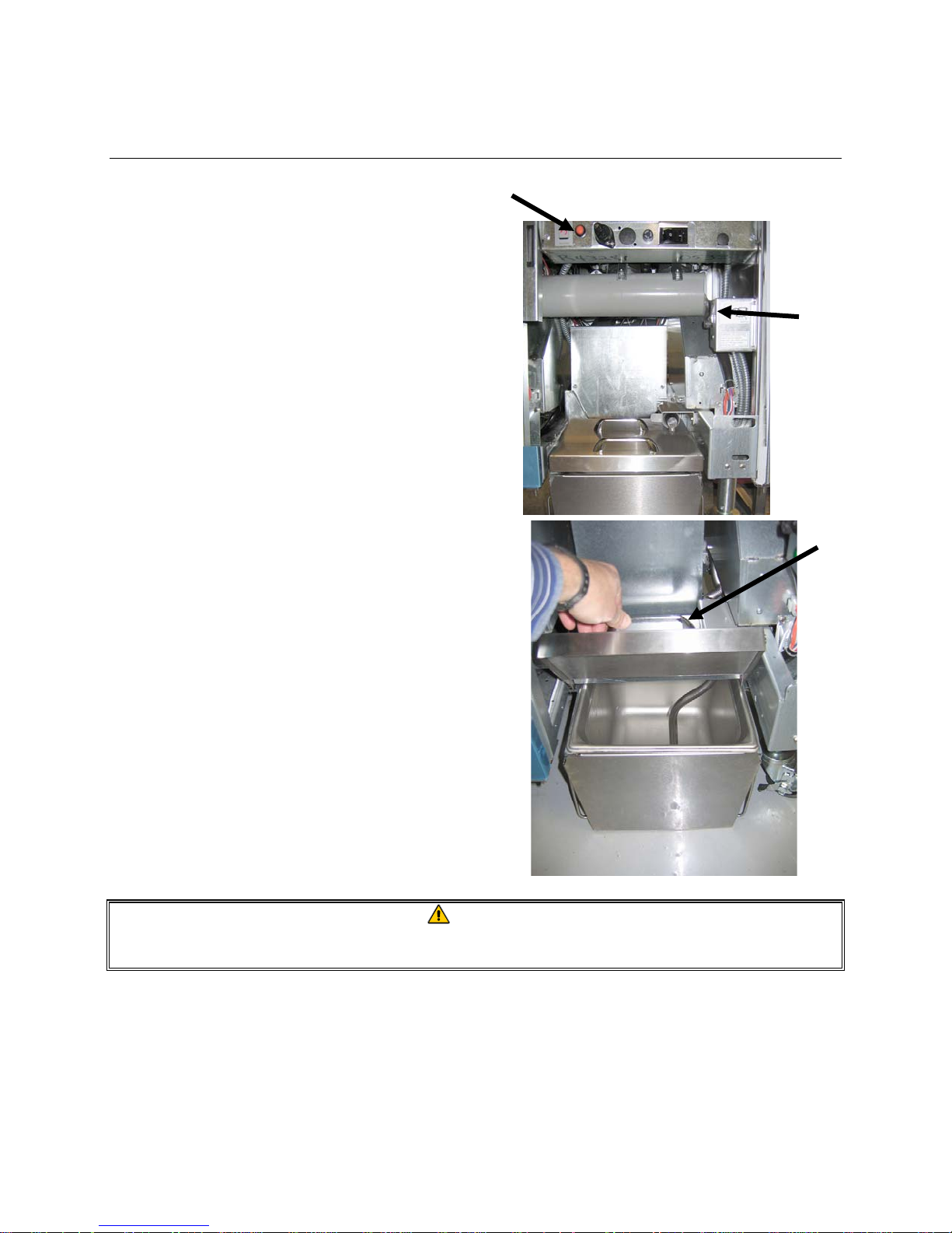
BIELA14-T SERIES GEN III LOV™ ELECTRIC FRYER
APPENDIX E: Solid Shortening Melting Unit Use
Reset oil reservoir system
Ensure shortening melting unit is on.
Fill melting unit with shortening.
Allow 2-3 hours for solid shortening to melt. DO
NOT press the orange reset button until the
shortening has had time to melt. The low oil
reservoir light will come on if the fryer calls for oil
before the shortening in the melting unit is liquid.
Once the shortening is fully melted, press and
hold the orange reset button to turn off the light
and reset the top off system.
DO NOT ADD hot oil to the shortening melter. The
temperature of the oil reservoir should not exceed
140°F (60°C). Add small amounts of solid
shortening to the reservoir to ensure it has
sufficient oil to operate the top-off system.
Melting
unit
power
switch
Lift carefully
to add
shortening.
For best results, DO NOT TURN OFF the solid
shortening melting unit overnight.
The power switch for the melting unit is also used
as a reset switch if the system’s high limit
temperature is reached.
WARNING
The surfaces of the solid shortening heater are hot. Do not touch with bare hands. Wear protective
clothing when adding shortening to the melting unit.
C–1
Page 81

THIS PAGE INTENTIONALLY LEFT BLANK
Page 82
8700LINEAVENUE,SHREVEPORT,LA71106‐6800
FRYMASTER
WWW.FRYMASTER.COM
800‐551‐8633
318‐865‐1711
Welbiltprovidestheworld’stopchefs,andpremierchainoperatorsorgrowingindependentswithindustryleadingequipmentandsolutions.
Ourcutting‐edgedesignsandleanmanufacturingtacticsarepoweredbydeepknowledge,operatorinsights,andculinaryexpertise.
AllofourproductsarebackedbyKitchenCare®–ouraftermarket,repair,andparts
CLEVELAND
CONVOTHERM®
©2018 Welbilt Inc. except where explicitly stated otherwise. All rights reserved. Continuing product improvement may necessitate change of specifications without
notice.
Part Number FRY_IOM_8197340 10/2018
DELFIELD®
FITKITCHEN™
*8197423*
service.
FRYMASTER®
GARLAND
KOLPAK®
LINCOLN
MANITOWOC®
MERCO®
WWW.WELBILT.COM
MERRYCHEF®
MULTIPLEX®
 Loading...