

Frymaster FM45E, MJ45E, MJ45EC, FM45EC Installation & Operation Manual
45 Series Gas Fryers
Installation & Operation Manual
Frymaster, a member of the Commercial Food Equipment Service Association, recommends
using CFESA Certified Technicians.
24-Hour Service Hotline 1-800-551-8633
819-0002
08-00
DANGER
IMPROPER INSTALLATION, ADJUSTMENT, ALTERATION, SERVICE, OR
MAINTENANCE CAN CAUSE PROPERTY DAMAGE, INJURY, OR DEATH. READ THE
INSTALLATION, OPERATING, AND SERVICE INSTRUCTIONS THOROUGHLY
BEFORE INSTALLING OR SERVICING THIS EQUIPMENT.
DANGER
FOR YOUR SAFETY, DO NOT STORE OR USE GASOLINE OR OTHER FLAMMABLE
LIQUIDS OR VAPORS IN THE VICINITY OF THIS OR ANY OTHER APPLIANCE.
DANGER
POST IN A PROMINENT LOCATION THE INSTRUCTIONS TO BE FOLLOWED IN THE
EVENT THE USER SMELLS GAS. THIS INFORMATION SHALL BE OBTAINED BY
CONSULTING THE LOCAL GAS SUPPLIER.
THIS EQUIPMENT IS TO BE INSTALLED IN COMPLIANCE WITH THE BASIC
PLUMBING CODE OF THE BUILDING OFFICIALS AND CODE ADMINISTRATORS
INTERNATIONAL, INC. (BOCA) AND THE FOOD SERVICE SANITATION MANUAL OF
THE FOOD AND DRUG ADMINISTRATION.
COMPUTERS
FCC
This device complies with Part 15 of the FCC rules. Operation is subject to the following two
conditions: 1) This device may not cause harmful interference, and 2) This device must accept any
interference received, including interference that may cause undesired operation. While this device is
a verified Class A device, it has been shown to meet the Class B limits.
CANADA
This digital apparatus does not exceed the Class A or B limits for radio noise emissions as set out by
the ICES-003 standard of the Canadian Department of Communications.
Cet appareil numerique n’emet pas de bruits radioelectriques depassany les limites de classe A et B
prescrites dans la norme NMB-003 edictee par le Ministre des Communcations du Canada.
DANGER
THIS PRODUCT CONTAINS CHEMICALS KNOWN TO THE STATE OF CALIFORNIA
TO CAUSE CANCER AND/OR BIRTH DEFECTS OR OTHER REPRODUCTIVE HARM.
Operation, installation, and servicing of this product could expose you to airborne
particles of glasswool or ceramic fibers, crystalline silica, and/or carbon monoxide.
Inhalation of airborne particles of glasswool or ceramic fibers is known to the State
of California to cause cancer. Inhalation of carbon monoxide is known to the State
of California to cause birth defects or other reproductive harm.
FRYMASTER FRYERS EQUIPPED WITH LEGS ARE FOR PERMANENT
INSTALLATION. FOR MOVEABLE OR PORTABLE INSTALLATION, FRYMASTER
OPTIONAL EQUIPMENT CASTERS MUST BE USED.
QUESTIONS??? CALL 1-800-551-8633.

45 SERIES GAS FRYERS
TABLE OF CONTENTS
CHAPTER 1: General Information
1.1 Parts Ordering and Service Information............................................................................ 1-1
1.2 Safety Information............................................................................................................. 1-1
1.3 European Community (CE) Specific Information............................................................. 1-2
1.4 Equipment Description...................................................................................................... 1-2
1.5 Installation, Operating, and Service Personnel ................................................................. 1-3
1.6 Definitions......................................................................................................................... 1-3
1.7 Shipping Damage Claim Procedure.................................................................................. 1-3
CHAPTER 2: Installation Instructions
2.1 General Installation Requirements.................................................................................... 2-1
2.2 Caster/Leg Installation ......................................................................................................2-2
2.3 Pre-Connection Preparations............................................................................................. 2-3
2.4 Connection to Gas Line..................................................................................................... 2-4
2.5 Converting to Another Gas Type ...................................................................................... 2-6
CHAPTER 3: Operating Instructions
3.1 Start-Up Procedure............................................................................................................ 3-1
3.2 Boiling-Out the Frypot......................................................................................................3-2
3.3 Shutting the Fryer Down...................................................................................................3-3
3.4 Controller Operation and Programming............................................................................ 3-3
Computer Magic III Controller ......................................................................................... 3-4
Thermostat Controller....................................................................................................... 3-8
Analog Controller.............................................................................................................. 3-9
Digital Controller ............................................................................................................ 3-10
Solid State Basket Lift Timer.......................................................................................... 3-11
CHAPTER 4: Filtration Instructions
4.1 Draining and Manual Filtering.......................................................................................... 4-1
4.2 Filter Magic II Filtration System Operation...................................................................... 4-1
Preparing the Filter Unit for Use....................................................................................... 4-2
Operation of the Filter Unit............................................................................................... 4-3
Changing the Filter Paper.................................................................................................. 4-4
CHAPTER 5: Preventive Maintenance
5.1 Fryer Preventive Maintenance Checks and Services ........................................................ 5-1
Daily Checks and Services................................................................................................ 5-1
Weekly Checks and Services ............................................................................................ 5-1
Quarterly Checks and Services.......................................................................................... 5-2
Semi-Annual Checks and Services.................................................................................... 5-4
5.2 Filter Magic II Filtration System Preventive Maintenance Checks and Services............. 5-5
i

45 SERIES GAS FRYERS
TABLE OF CONTENTS
CHAPTER 6: Operator Troubleshooting
6.1 Introduction........................................................................................................................6-1
6.2 Troubleshooting Fryers with Thermostat Controls............................................................6-2
6.3 Troubleshooting Fryers with Analog, Digital, or CM III Controllers...............................6-4
6.4 Troubleshooting the Filter Magic II Filtration System......................................................6-7
6.5 Troubleshooting Abnormal Burner Operation.................................................................6-11
6.6 Replacing the Controller or Controller Wiring Harness..................................................6-12
ii
45 SERIES GAS FRYERS
CHAPTER 1: GENERAL INFORMATION
1.1 Parts Ordering and Service
Information
In order to assist you as quickly as possible,
the Frymaster Factory Authorized Service
Center (FASC) or Service Department representative requires certain information about
your equipment. Most of this information is
printed on a data plate affixed to the inside of
the fryer door.
Parts orders must be placed directly with your
local FASC or distributor. Included with
fryers when shipped from the factory is a list
of Frymaster FASCs. If you do not have
access to this list, contact the Frymaster
Technical Service Department at 1-800-5518633 or 1-318-865-1711.
When ordering parts, the following information is required:
ready any other information that you think
may be helpful in solving your problem.
RETAIN AND STORE THIS MANUAL IN A SAFE
PLACE FOR FUTURE USE.
1.2 Safety Information
Before attempting to operate your unit, read
the instructions in this manual thoroughly.
Throughout this manual, you will find notations enclosed in double-bordered boxes
similar to the ones below.
CAUTION boxes contain information about
actions or conditions that may cause or result
in a malfunction of your system.
CAUTION
Example of a CAUTION box.
Model Number:
Serial Number:
Type of Gas or Voltage:
Item Part Number:
Quantity Needed:
Service information may be obtained by
contacting your local FASC. Information may
also be obtained by calling the Frymaster
Technical Service Department at 1-800-5518633 or 1-318-865-1711.
When requesting service, please have the following information ready:
Model Number:
Serial Number:
Type of Gas:
In addition to the model number, serial number, and type of gas, please be prepared to describe the nature of the problem and have
WARNING boxes contain information about
actions or conditions that may cause or result
in damage to your system, and which may
cause your system to malfunction.
WARNING
Example of a WARNING box.
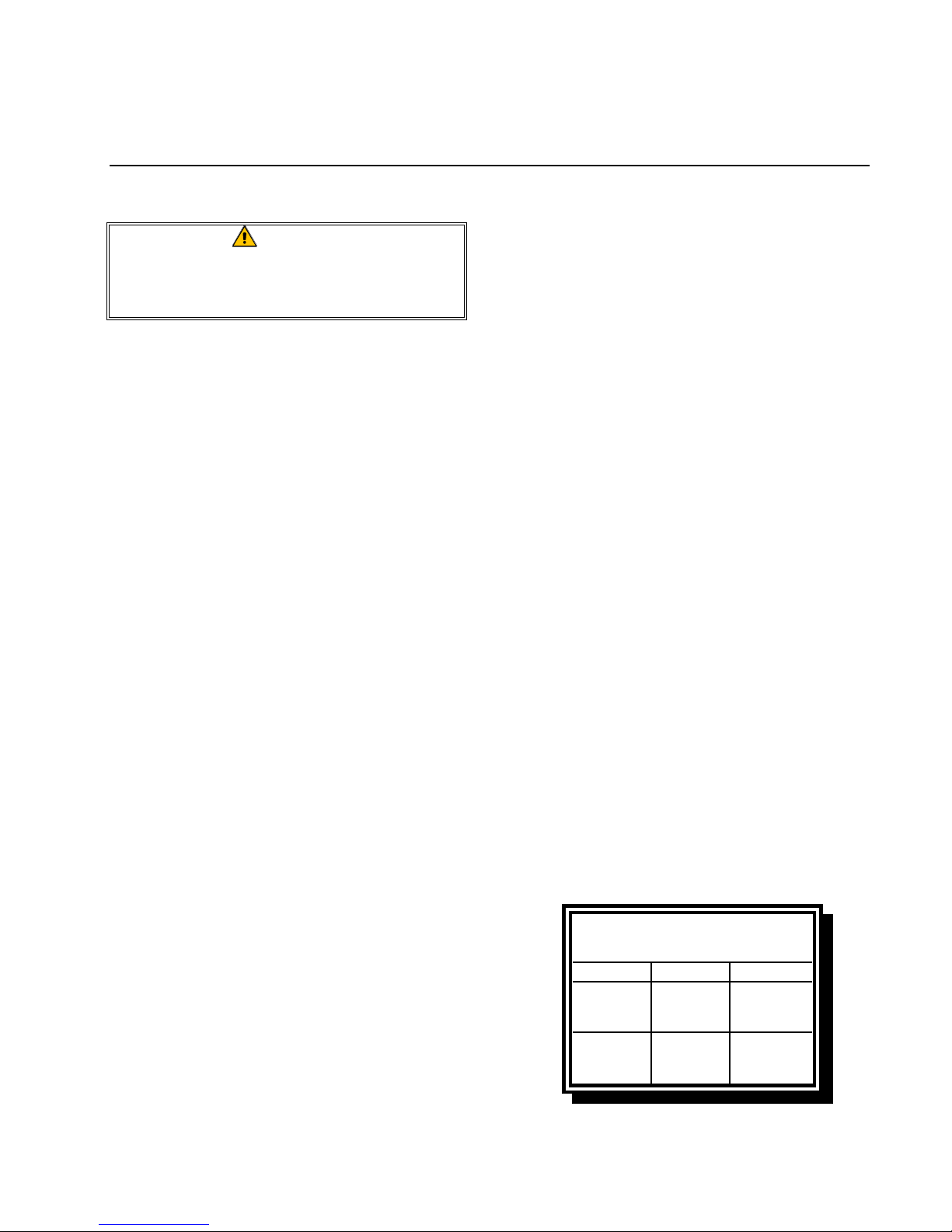
DANGER boxes contain information about ac-
tions or conditions that may cause or result in
injury to personnel, and which may cause
damage to your system and/or cause your system to malfunction.
DANGER
Hot cooking oil or shortening causes
severe burns. Never attempt to move a
fryer containing hot cooking
oil/shortening or to transfer hot
cooking oil/shortening from one
container to another.
1-1
45 SERIES GAS FRYERS
CHAPTER 1: GENERAL INFORMATION
Your fryer is equipped with automatic safety
features:
1. High temperature detection shuts off gas to
the burner assembly should the controlling
thermostat fail.
2. A safety switch built into the drain valve
of units with built-in filtration systems
prevents burner ignition with the drain
valve even partially open.
1.3 European Community (CE)
Specific Information
The European Community (CE) has established certain specific standards regarding
equipment of this type. Whenever there is a
difference between CE and non-CE standards,
the information or instructions concerned are
identified by shadowed boxes similar to the
one below.
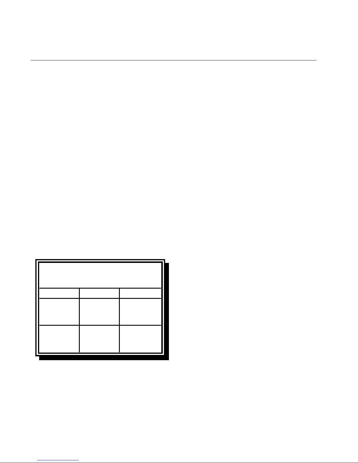
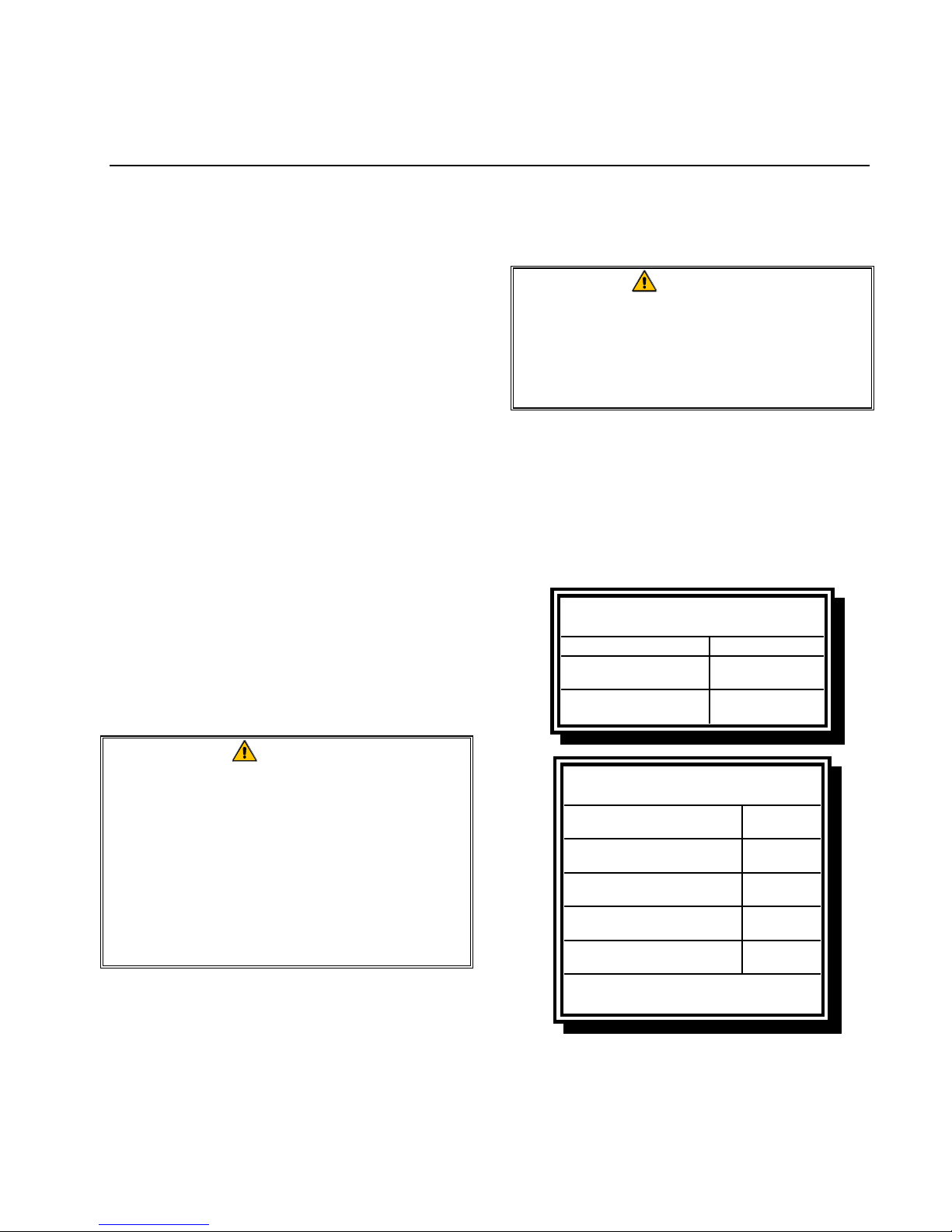
Non-CE Standard
for Incoming Gas Pr essur es
Gas Minimum Maximum
6" W.C.
Natural
LP
1.49 kPa
14.93 mbar
11" W.C.
2.74 kPa
27.37 mbar
1.4 Equipment Description
45 Series gas fryers are specifically designed
for high volume frying. Models in this series
include FM45E, FM45EC, MJ45E, and
MJ45EC variants. Fryers in this series may be
equipped with built-in Filter Magic filtration
14" W.C.
3.48 kPa
34.84 mbar
14" W.C.
3.48 kPa
34.84 mbar
systems (FM45E and FM45EC variants), or
may be configured for manual filtration
(MJ45E and MJ45EC variants). All models
may be configured for electrical power supplies ranging from 120 to 240 VAC.
45 Series fryers utilize a combination gas
valve to control the burner and require an external source of AC electrical power. On the
FM45E and MJ45E models, the electrical
power supply to the gas valve is controlled by
a manually operated thermostat controller or
an electronic controller. The FM45EC and
MJ45EC models are equipped with Computer
Magic III computers.
All models are of an open-pot design with no
tubes and have a hand-sized opening into the
deep cold zone, which makes cleaning the
stainless frypot quick and easy.
Fryers equipped with built-in filtration systems are shipped completely assembled. Fryers without built-in filtration require installation of legs or optional casters at point of use.
All fryers are shipped with a package of standard accessories. Each fryer is adjusted,
tested, and inspected at the factory before
crating for shipment.
Frypots are constructed of welded, heavygauge stainless steel. Heating is supplied by a
burner assembly having multiple gas jets,
which are focused on ceramic targets located
around the lower side of the frypot. The burner
assembly can be configured for natural gas,
propane, or manufactured gas, as required by
the customer. A drain is tapped into the center
of the frypot, with a front-controlled manual
ball valve.
Each fryer is equipped with a thermostat probe
for precise temperature control. The probe is
located on the centerline of the frypot for rapid
1-2

45 SERIES GAS FRYERS
CHAPTER 1: GENERAL INFORMATION
response to changes in loads and to provide
the most accurate temperature measurement.
45 Series fryers may be equipped with an optional melt cycle feature which pulses the
burner on and off at a controlled rate. The
melt cycle feature is designed to prevent
scorching and uneven heating of the frypot for
customers who use solid shortening.
The controls on your fryer vary depending on
the model and configuration purchased. Control options include thermostat controls (standard), analog controllers, digital controllers, or
Com puter Magic III compu ters. Each t ype is
covered in detail in Chapter 3, Fryer Operating
Instructions.
1.5 Installation, Operating, and
Service Personnel
Operating information for Frymaster equipment has been prepared for use by qualified
and/or authorized personnel only, as defined in
Section 1.6.
All installation and service on Frymaster
equipment must be performed by qualified,
certified, licensed, and or/authorized installation or service personnel, as defined in
Section 1.6.
1.6 Definitions
operation of the equipment covered in this
manual.
QUALIFIED INSTALLATION PERSONNEL
Qualified installation personnel are individuals, or firms, corporations, or companies
which, either in person or through a representative, are engaged in and are responsible for
the installation of gas-fired appliances. Qualified personnel must be experienced in such
work, be familiar with all gas precautions involved, and have complied with all requirements of applicable national and local codes.
QUALIFIED SERVICE PERSONNEL
Qualified service personnel are those that are
familiar with Frymaster equipment and who
have been authorized by Frymaster to perform service on Frymaster equipment. All
authorized service personnel are required to be
equipped with a complete set of service and
parts manuals, and to stock a prescribed
minimum amount of Frymaster equipment
parts.
A list of Frymaster Factory Authorized Service Centers (FASC) was included with the
fryer when it was shipped from the factory.
Failure to use qualified service personnel
will void the Frymaster Warranty on your
equipment.
QUALIFIED AND/OR AUTHORIZED OPERATING
PERSONNEL
Qualified/authorized operating personnel are
those who have carefully read the information
in this manual and have familiarized
themselves with the equipment functions, or
who have had previous experience with the
1.7 Shipping Damage Claim
Procedure
Your Frymaster equipment was carefully inspected and packed before leaving the factory.
The transportation company assumes full responsibility for safe delivery upon acceptance
of the equipment for transport.
1-3

45 SERIES GAS FRYERS
CHAPTER 1: GENERAL INFORMATION
What to do if your equipment arrives
damaged:
1. File a claim for damages immediately,
regardless of the extent of damages.
2. In spect for and record all vi sible loss or
damage, and ensure that this information
is noted on the freight bill or express receipt and is signed by the person making
the delivery.
Frymaster DOES NOT ASSUME
RESPONSIBILITY FOR DAMAGE OR LOSS
INCURRED IN TRANSIT.
3. Concealed loss or damage that was un-
noticed until the equipment was unpacked
should be recorded and reported to the
freight company or carrier immediately
upon discovery. A concealed damage
claim must be submitted within 15 days of
the date of delivery. Ensure that the shipping container is retained for inspection.
1-4
45 SERIES GAS FRYERS
CHAPTER 2: INSTALLATION INSTRUCTIONS
2.1 General Installation
Requirements
PROPER INSTALLATION IS ESSENTIAL FOR
EFFICIENT, TROUBLE-FREE OPERATION OF
YOUR FRYER. ANY UNAUTHORIZED ALTERATIONS MADE TO THIS EQUIPMENT WILL
VOID THE FRYMASTER
WARRANTY.
Upon arrival, inspect the fryer carefully for
visible or concealed damage. (See Shipping
Damage Claim Procedure in Chapter 1.)
CLEARANCE AND VENTILATION
The fryer(s) must be installed with a 6” (150
mm) clearance at both sides and back when
installed adjacent to combustible construction;
no clearance is required when installed adjacent to noncombustible construction. A
minimum of 24” (600 mm) clearance should
be provided at the front of the fryer.
Adequate distances must be maintained from
the flue outlet of the fryer to the lower edge of
the ventilation filter bank. Filters should be
installed at an angle of 45º. Place a drip tray
beneath the lowest edge of the filter. For U.S.
installation, NFPA standard No. 96 states, “A
minimum distance of 18 in. (450 mm) should
be maintained between the flue outlet and the
lower edge of the grease filter.” Frymaster
recommends that the minimum distance be 24
in. (600 mm) from the flue outlet to the bottom
edge of the filter when the appliance consumes
more than 120,000 BTU per hour.
Information on construction and installation of
ventilating hoods can be found in the NFPA
standard cited above. A copy of the standard
may be obtained from the National Fire Protection Association, Battery March Park,
Quincy, MA 02269.
One of the most important considerations of
efficient fryer operation is ventilation. Make
sure the fryer is installed so that products of
combustion are removed efficiently, and that
the kitchen ventilation system does not produce drafts that interfere with proper burner
operation.
The fryer flue opening must not be placed
close to the intake of the exhaust fan, and the
fryer must never have its flue extended in a
“chimney” fashion. An extended flue will
change the combustion characteristics of the
fryer, causing longer recovery time. It also
frequently causes delayed ignition. To provide the air flow necessary for good combustion and burner operation, the areas surrounding the fryer front, sides, and rear must be kept
clear and unobstructed.
Fryers must be installed in an area with an
adequate air supply and adequate ventilation.
DANGER
Do not attach an apron drainboard to a
single fryer. The fryer may become
unstable, tip over, and cause injury.
The appliance area must be kept free
and clear of combustible materials at
all times.
NATIONAL CODE REQUIREMENTS
The type of gas for which the fryer is equipped
is stamped on the data plate attached to the
inside of the fryer door. Connect a fryer
stamped “NAT” only to natural gas, those
stamped “PRO” only to propane gas, and
those stamped “MFG” only to manufactured
gas.
Installation shall be made with a gas connector
that complies with national and local codes,
and, where applicable, CE codes. QuickDisconnect devices, if used, shall likewise
2-1
45 SERIES GAS FRYERS
CHAPTER 2: INSTALLATION INSTRUCTIONS
comply with national, local, and, if applicable,
CE codes.
ELECTRICAL GROUNDING REQUIREMENTS
All electrically operated appliances must be
grounded in accordance with all applicable
national and local codes, and, where applicable, CE codes. A wiring diagram is located on
the inside of the fryer door. Refer to the rating
plate on the inside of the fryer door for proper
voltages.
DANGER
If this appliance is equipped with a
three-prong (grounding) plug, it must
be plugged directly into a properly
grounded receptacle.
Do not cut or remove the grounding
prong from the plug.
DANGER
This equipment requires electrical
power for operation.
Place the gas control valve in the OFF
position in case of a prolonged power
outage.
limits for a Class A digital device, pursuant to
Part 15 of the FCC rules. While these devices
are verified as Class A devices, they have been
shown to meet the Class B limits. These limits are designed to provide reasonable protection against harmful interference when the
equipment is operated in a commercial environment. This equipment generates, uses, and
can radiate radio frequency energy and, if not
installed and used in accordance with the instruction manual, may cause harmful interference to radio communications. Operation of
the equipment in a residential area is likely to
cause harmful interference in which case the
user will be required to correct the interference
at his own expense.
If necessary, the user should consult the dealer
or an experienced radio and television technician for additional suggestions.
The user may find the booklet “How to Identify and Resolve Radio-TV Interference Problems” helpful. It is prepared by the Federal
Communications Commission and is available
from the U.S. Government Printing Office,
Washington, DC 20402, Stock No. 004-00000345-4.
2.2 Caster/Leg Installation
Do not attempt to use the equipment
during a power outage.
FCC COMPLIANCE
The user is cautioned that any changes or
modifications to Frymaster computers not expressly approved by the party responsible for
compliance could void the user’s authority to
operate the equipment. Frymaster computers
have been tested and found to comply with the
Depending upon the specific configuration
ordered, your fryer may have been shipped
without installed casters or legs. If casters or
legs are installed, you may skip this section
and proceed to Section 2.3, Pre-Connection
Preparations.
If your fryer requires the installation of
casters/legs, install them in accordance with
the instructions inclu ded in your accessory
package.
2-2
45 SERIES GAS FRYERS
CHAPTER 2: INSTALLATION INSTRUCTIONS
2.3 Pre-Connection Preparations
DANGER
Do not connect fryer to gas supply
before completing each step
in this section.
After the fryer has been positioned under the
fry station exhaust hood, ensure the following
has been accomplished:
1. Adequate means must be provided to limit
the movement of fryers without depending
upon the gas line connections. If a flexible
gas hose is used, a restraining cable must
be connected at all times when the fryer is
in use. The restraining cable and installation instructions are packed with the flexible hose in the accessories box that was
shipped with your unit.
4. Test the fryer electrical system:
a. Plug the fryer electrical cord(s) into a
grounded electrical receptacle.
b. Place the power switch in the ON
position.
• For fryers equipped with thermo-
stat controls, verify that the power
and heat lights are lit.
• For fryers having computer or
digital displays, verify that the display indicates CYCL.
c. Place the fryer power switch in the
OFF position. Verify that the power
and heat lights are out, or that the display is blank.
2. Single unit fryers must be stabilized by
installing restraining chains on fryers
equipped with casters or anchor straps on
fryers equipped with legs. Follow the instructions shipped with the casters/legs to
properly install the chains or straps.
3. Level fryers equipped with legs by screwing out the legs approximately 1 inch then
adjusting them so that the fryer is level and
at the proper height in the exhaust hood.
Frymaster recommends that the minimum
distance from the flue outlet to the bottom
edge of the filter be 24 in. (600 mm) when
the appliance consumes more than 120,000
BTU per hour.
For fryers equipped with casters, there are
no built-in leveling devices. The floor
where the fryer is to be installed must be
level.
5. Refer to the data plate on the inside of the
fryer door to determine if the fryer burner
is configured for the proper type of gas before connecting the fryer quick-disconnect
device or piping from the gas supply line.
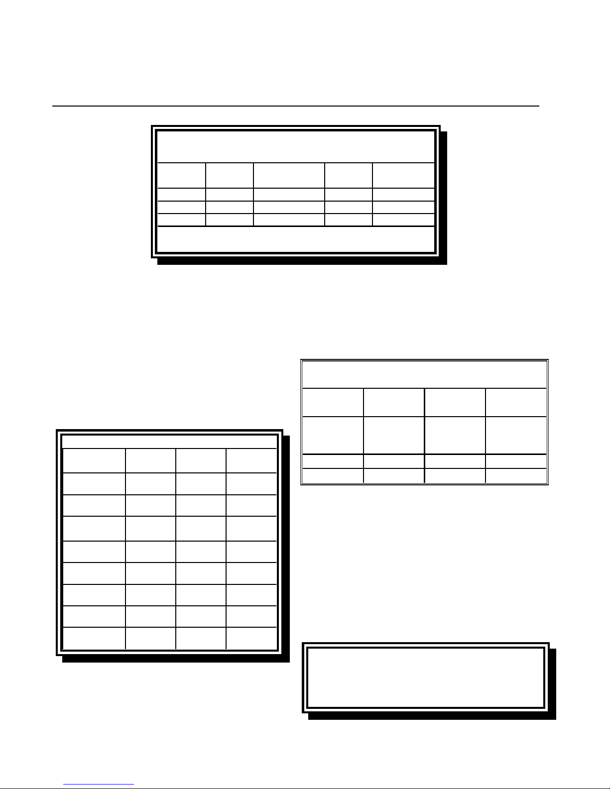
6. Verify the minimum and maximum gas
supply pressures for the type of gas to be
used in accordance with the accompanying
tables.
Non-CE Standard
for Incoming Gas Pressures
Gas Minimum Maximum
Natural
LP
6" W.C.
1.49 kPa
14.93 mbar
11" W.C.
2.74 kPa
27.37 mbar
14" W.C.
3.48 kPa
34.84 mbar
14" W.C.
3.48 kPa
34.84 mbar
2-3
45 SERIES GAS FRYERS
d
O
CHAPTER 2: INSTALLATION INSTRUCTIONS
CE Standar
for Incoming G as Pressure s
Pressure
Gas
G20 20 18 x 1,40 mm 7,5 mbar
G25 20 - 25 18 x 1,40 mm 10 mbar
G31 37 - 50 18 x 0,86 mm 20,6 mbar
(mbar )
(1)
Regulator
Pressure ConsumptionOrifice Diameter
3
3,00 m
3
3,50 m
2,21 kg/h
/h
/h
(1) mbar = 10,2 m m H
2
7. For fryers equipped with a Filter Magic II
system and/or basket lifts, plug the electrical cord(s) into a power receptacle behind
the fryer.
2.4 Connection to Gas Line
The 45 Series fryer has received the CE mark
for the countries and gas categories indicated
in the accompanying table.
CE Approved Gas Categories
Pressure
Country Category Gas
BE
DE
DK-GR-IT
I2E+(S)
I3P
I2 ELL
13P
I2 H G20 20
G20/G25
G31
G20/G25
G31
(mbar)
20/25
37
20
50
This may cause slow recovery and delayed
ignition. The incoming gas supply line should
be a minimum of 1½” (38 mm) in diameter.
Refer to the chart below for the minimum
sizes of connection piping.
Gas Connection Pipe Sizes
(Minimum incoming pipe size should be 1 1/2" (38 mm))
4 or more
Gas Single Unit 2 - 3 Units
Natural
Propane 1/2" (13 mm) 3/4" (19 mm) 1" (25 mm)
Manufactured 1" (25 mm) 1 1/4" (33 mm) 1 1 /2" (38 mm)
3/4
" (19 mm) 1" (25 mm)
* For distances of more than 20 feet (6 m ) and/or
more than 4 fittings or elbows, increase the connection by one pipe size.
units*
Use two 1"
(25mm)
connections
FR
LU
ES
NL
IE-PT-GB
II2Esi3P
I2E G20/G25 20/25
II2H3P
II2L3P
II2H3P
G20/G25
G31
G20
G31
G25
G31
G20
G31
The size of the gas line used for installation is
very important. If the line is too small, the gas
pressure at the burner manifold will be low.
20/25
37 ET 50
20
37 ET 50
25
50
20
37
Before connecting new pipe to your unit, the
pipe must be thoroughly blown out to remove
any foreign particles. If these foreign particles
get into the burner and controls, they will
cause improper and sometimes dangerous operation.
CE Standard
CE regulations require a combustion air supply of 2m3/h per kW per fryer. (See rating
plate affixed to door for kW rating.)
2-4
45 SERIES GAS FRYERS
CHAPTER 2: INSTALLATION INSTRUCTIONS
1. Connect the quick-disconnect hose to the
fryer quick-disconnect fitting under the
front of the fryer and to the building gas
line.
NOTE: Some fryers are configured for a
rigid connection to the gas supply line.
These units are connected to the gas supply line at the rear of the unit.
When using thread compound, use very
small amounts on male threads only. Use
a pipe thread compound that is not affected by the chemical action of LP gases
(Loctite™ PST56765 Sealant is one such
compound). DO NOT apply compound to
the first two threads. This will ensure that
the burner orifices and control valve do
not become clogged.
2. Open the gas supply to the fryer and check
all piping, fittings, and gas connections for
leaks. A soap and water solution should
be used for this purpose.
the “Lighting Instructions” and “Boiling
Out the Frypot” topics found in Chapter 3
of this manual.
WARNING
“Dry-firing” your unit will cause
damage to the frypot. Always ensure
that melted shortening, cooking oil, or
water and boil-out solution is in the
frypot before firing your unit.
4. It is suggested that the burner manifold
pressure be checked at this time by the local gas company or an authorized service
agent. Refer to “Check Burner Manifold
Pressure” in Chapter 5 of this manual for
the proper procedure.
Non-CE Standard
Burner Manifold Gas Pressures
Gas Pressure
Natural
LP
3.5" W.C.
0.87 kPa
8.25" W.C.
2.05 kPa
DANGER
Never use matches, candles, or any
other ignition source to check for
leaks.
If gas odors are detected, shut off the
gas supply to the fryer at the main
shut-off valve and contact the local gas
company or an authorized service
agency for service.
3. Close the fryer drain valve and fill the fry-
pot with water and boil-out solution to the
bottom OIL-LEVEL line at the rear of the
frypot. Light the fryer and perform the
boil-out procedures that are described in
CE Standard
Burner Manifold Gas Pressures
Gas
Natural Gas Lacq
(G20) under 20 mbar
Natural Gas Gronique *
(G25) under 25 mbar
Natural Gas Gronique
(G20) under 20 mbar
Propane
(G31) under 37 or 50 mbar
* Belgian G25 = 7,0 mbar
Pressure
(mbar)
7,5
10
10
20,6
5. Check the thermostat calibration or tem-
perature programmed into the computer.
2-5
45 SERIES GAS FRYERS
CHAPTER 2: INSTALLATION INSTRUCTIONS
• For units equipped with thermostat
controls, refer to the Thermostat Calibration instructions in Chapter 7.
• For units equipped with other types of
controllers, refer to the Set Point programming instructions in Chapter 3.
2.5 Converting to Another Gas Type
Your fryer is configured at the factory for either natural gas or Propane (LP) gas.
If you desire to switch from one type of gas to
another, a gas conversion kit must be installed by a Factory Authorized Service
Center technician.
CE Gas Conversion Instructions
1. Between G20- and G25-type Natural Gas,
adjust the gas pressure at the regulator.
(Refer to the CE Standard Burner Manifold Gas Pressure Chart.) Do not change
the orifice or pilot.
2. Between a 2nd family gas (G20 or G25)
and a 3rd family gas (G31 Propane):
a. Change the orifices.
b. Change the pilot.
c. Change the gas valve regulator.
d. Adjust the manifold pressure.
DANGER
Switching to a different type of gas
without installing the proper
conversion kit may result in fire or
explosion!
NEVER ATTACH YOUR FRYER TO A
GAS SUPPLY FOR WHICH IT IS NOT
CONFIGURED!
Non-CE Gas Conversion Instructions
Call
Frymaster
Frymaster
FrymasterFrymaster
Service (1-800-551-8633) to
determine the conversion kit appropriate for
your configuration and altitude. Contact your
local FASC to order the kit and arrange for
installation.
3. Remove the rating plate and install a new
one. Call your local service agency or
KES for a new rating plate.
4. If the destination language changes, re-
place the labels. Call you local service
agency of kitchen equipment supplier for a
label kit. The language of reference will
be on the corner of the label.
The following gas-conversion components and
kits are available from your FASC:
Propane (G31) to Natural (G20/G25)
Regulator only: P/N 810-1288
Pilot, regulator, and orifices kit: P/N 826-1201
Natural (G20/G25) to Propane (G31)
Regulator only: P/N 810-1292
Pilot, regulator, and orifices kit: P/N 826-1200
2-6
45 SERIES GAS FRYERS
CHAPTER 3: OPERATING INSTRUCTIONS
3.1 Start-Up Procedure
CAUTION
If this is the first time the fryer is being
used after installation, refer to Section
3.2, Boil-Out Procedure.
Knob is shown in
OFF position.
CAUTION
The cooking oil/shortening capacity of
the 45 Series fryer is 50 lbs (25 liters)
at 70ºF (21ºC).
Before lighting the fryer, make sure the
fryer is OFF and the frypot drain valve
is closed. Remove the basket support
rack, if installed, and fill the frypot to
the bottom OIL-LEVEL line.
To prevent scorching, if solid
shortening is being used, make sure it
is tightly packed down into the bottom
of the frypot.
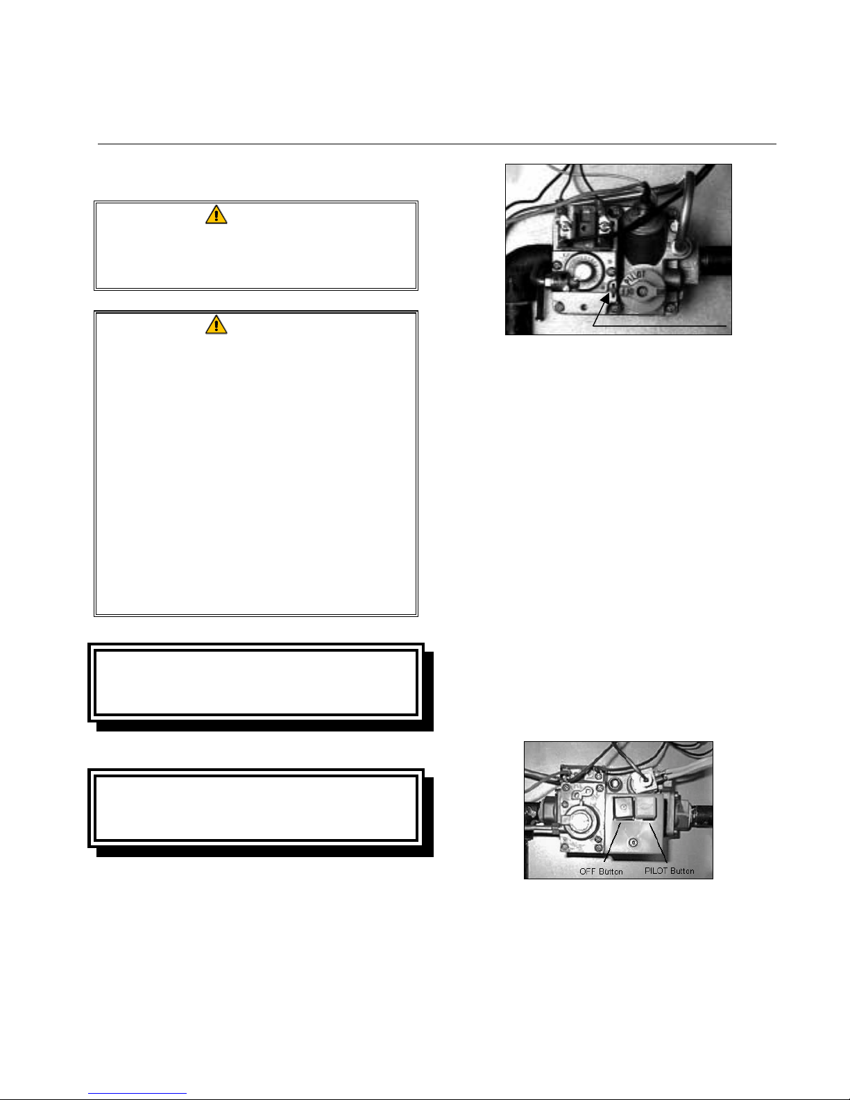
Non-CE Standard
Units configured to Non-CE standards are
equipped with Robertshaw valves.
Note index mark.
3. Place a flame near the pilot assembly, push
and hold the knob in, light the pilot, and
continue to depress the knob for at least 60
seconds after the pilot lights. Failure to
hold the knob in long enough will cause
the pilot to go out when the knob is released. If the pilot goes out when the knob
is released, wait at least 5 minutes then repeat this step.
4. Turn the gas valve knob to the ON position.
Lighting the Pilot on Honeywell Valves:
1. Ensure power to the unit is OFF.
2. Press the OFF (red) button. Wait 5 minutes.
CE Standard
Units configured to CE standards are
equipped with Honeywell valves.
Lighting the Pilot on Robertshaw Valves:
1. Ensure power to the unit is OFF.
2. Turn the gas valve knob to the OFF position. Wait 5 minutes, then turn the knob
to the PILOT position.
3. Place a flame near the pilot assembly, push
and hold the PILOT (white) button in,
light the pilot, and continue to depress the
button for at least 60 seconds after the
pilot lights. Failure to hold the button in
long enough will cause the pilot to go out
3-1
 Loading...