

Page 1
FPD65 Series with Built-In Filtration
Frymaster FPD65 Series
Installation & Operation Manual
Gas Fryers
PARTS LIST
INCLUDED
Frymaster, a member of the Commercial Food Equipment Service Association, recommends
using CFESA Certified Technicians.
24-Hour Service Hotline 1-800-551-8633
SEPT 2008
*8196039*
Page 2
Please read all sections of this manual and retain for future reference.
NOTICE
This appliance is intended for professional use only and is to be operated by qualified
personnel only. A Frymaster/Dean Factory Authorized Service Center (FASC) or other qualified
professional should perform installation, maintenance, and repairs. Installation, maintenance,
or repairs by unqualified personnel may void the manufacturer’s warranty. See Chapter 1 of
this manual for definitions of qualified personnel.
NOTICE
This equipment must be installed in accordance with the appropriate national and local codes of
the country and/or region in which the appliance is installed. See NATIONAL CODE
REQUIREMENTS in Chapter 3 of this manual for specifics.
NOTICE
Drawings and photos used in this manual are intended to illustrate operational, cleaning and
technical procedures and may not conform to onsite management operational procedures.
NOTICE TO OWNERS OF UNITS EQUIPPED WITH COMPUTERS
U.S.
This device complies with Part 15 of the FCC rules. Operation is subject to the following two
conditions: 1) This device may not cause harmful interference, and 2) This device must accept
any interference received, including interference that may cause undesired operation. While
this device is a verified Class A device, it has been shown to meet Class B limits.
CANADA
This digital apparatus does not exceed the Class A or B limits for radio noise emissions as set
out by the ICES-003 standard of the Canadian Department of Communications.
Cet appareil numerique n’emet pas de bruits radioelectriques depassany les limites de classe A
et B prescrites dans la norme NMB-003 edictee par le Ministre des Communications du Canada.
NOTICE
IF, DURING THE WARRANTY PERIOD, THE CUSTOMER USES A PART FOR THIS ENODIS
EQUIPMENT OTHER THAN AN UNMODIFIED NEW OR RECYCLED PART PURCHASED
DIRECTLY FROM FRYMASTER/DEAN, OR ANY OF ITS AUTHORIZED SERVICE CENTERS,
AND/OR THE PART BEING USED IS MODIFIED FROM ITS ORIGINAL CONFIGURATION, THIS
WARRANTY WILL BE VOID. FURTHER, FRYMASTER/DEAN AND ITS AFFILIAT ES WILL NOT BE
LIABLE FOR ANY CLAIMS, DAMAGES OR EXPENSES INCURRED BY THE CUSTOMER WHICH
ARISE DIRECTLY OR INDIRECTLY, IN WHOLE OR IN PART, DUE TO THE INSTALLATION OF
ANY MODIFIED PART AND/OR PART RECEIVED FROM AN UNAUTHORIZED SERVICE CENTER.
NOTICE
The Commonwealth of Massachusetts requires any and all gas products to be installed by a
licensed plumber or pipe fitter.
Page 3
DANGER
Improper installation, adjustment, maintenance or service, and unauthorized alterations or
modifications can cause property damage, injury, or death. Read the installation, operating and
service instructions thoroughly before installing or servicing this equipment. Only qualified
service personnel may convert this appliance to use a gas other than that for which it was
originally configured. See Chapter 1 of this manual for definition of qualified service personnel.
DANGER
Adequate means must be provided to limit the movement of this appliance without depending
upon the gas line connection. Single fryers equipped with legs must be stabilized by installing
anchor straps. All fryers equipped with casters must be stabilized by installing restraining
chains. If a flexible gas line is used, an additional restraining cable must be connected at all
times when the fryer is in use.
DANGER
The front ledge of the fryer is not a step. Do not stand on the fryer. Serious injury can result
from slips or contact with the hot oil.
DANGER
Do not store or use gasoline or other flammable vapors and liquids in the vicinity of this or any
other appliance.
DANGER
Instructions to be followed in the event the operator smells gas or otherwise detects a gas leak
must be posted in a prominent location. This information can be obtained from the local gas
company or gas supplier.
DANGER
The crumb tray in fryers equipped with a filter system must be emptied into a fireproof container
at the end of frying operations each day. Some food particles can spontaneously combust if left
soaking in certain shortening material. Additional information can be obtained in the filtration
manual included with the system.
WARNING
No structural material on the fryer should be altered or removed to accommodate placement of
the fryer under a hood. Questions? Call the Frymaster/Dean Service Hotline at 1-800-551-8633.
WARNING
Do not bang fry baskets or other utensils on the fryer’s joiner strip. The strip is present to seal
the joint between the frypot. Banging fry baskets on the strip to dislodge shortening will distort
the strip, adversely affecting its fit. It is designed for a tight fit and should only be removed for
cleaning.
Page 4

FPD65 Series Gas Fryers
Installation & Operation Manual
TABLE OF CONTENTS
Page #
1. INTRODUCTION 1-1
1.1 After Purchase 1-1
1.2 Ordering Parts 1-1
1.3 Service Information 1-1
1.4 Computer Information 1-1
1.5 Safety Information 1-2
1.6 Service Personnel 1-3
2. IMPORTANT INFORMATION 2-1
2.1 Receiving and Unpacking Equipment 2-1
2.2 General 2-2
2.3 Principles of Operation 2-3
2.4 Rating Plate 2-3
2.5 Pre-Installation 2-3
2.6 Air Supply and Ventilation 2-5
2.7 Equipment Installed at High Altitudes 2-5
3. INSTALLATION 3-1
3.1 Installing the Fryer 3-1
3.2 Gas Connections 3-4
3.3 Adjustments/Adaptation to Different Gases 3-7
3.4 Electrical Connections 3-9
4. FRYER OPERATIONS 4-1
4.1 Initial Start-up 4-1
4.2 Boil-Out Procedure 4-3
4.3 Final Preparation 4-5
Page 5

FPD65 Series Gas Fryers
Installation & Operation Manual
TABLE OF CONTENTS (CONT.)
Page #
5. FILTRATION OPERATION 5-1
5.1 General 5-1
5.2 Filtration Preparation 5-1
5.3 Daily Filtration Operation 5-4
5.4 Operating the Filter 5-6
6. PREVENTATIVE MAINTENANCE 6-1
6.1 General 6-1
7. TROUBLESHOOTING 7-1
7.1 General 7-1
7.2 Pilot Burner Malfunction 7-2
7.3 Main Burner Malfunctions 7-2
7.4 Wiring Diagram, Main 7-4
7.5 Wiring Diagram, Filter 7-5
8. PARTS LIST 8-1
8.1 Cabinetry and Related Components 8-1
8.2 Doors, Topcaps and Related Components 8-3
8.3 Frypots, Burners and Related Components 8-4
8.4 Component Box Components 8-6
8.5 Filter Pan and Related Components 8-7
8.6 Oil-Drain Components 8-8
8.7 Oil-Return Components 8-10
8.8 Suction Tube, Oil-Return Components 8-11
Page 6

FRYMASTER FPD65 SERIES GAS FRYERS
CHAPTER 1: INTRODUCTION
1.1 After Purchase
In order to improve service, have the following chart filled in by the Frymaster/Dean Authorized
Service Technician who installed this equipment.
Authorized Service
Technician/FASC
Address
Telephone/Fax
Model Number
Serial Number
Gas Type
1.2 Ordering Parts
Customers may order parts directly from their local factory authorized service center. For this
address and phone number, contact your factory authorized service center or call the Frymaster/Dean
Service Hotline phone number, 1-800-551-8633.
To speed up your order, provide the model number, serial number, gas type, part needed, item part
number (if known), and quantity needed.
1.3 Service Information
Call the Frymaster/Dean Service Hotline, 1-800-551-8633, for the location of your nearest factory
authorized service center. To assist you more efficiently, always provide the service technician with
the model number, gas type, serial number, and the nature of the problem.
1.4 Computer Information
This equipment has been tested and found to comply with the limits for a Class A digital device,
pursuant to Part 15 of the FCC rules. While this device is a verified Class A device, it has been
shown to meet the Class B limits. These limits are designed to provide reasonable protection against
harmful interference when the equipment is operated in a commercial environment. This equipment
generates, uses and can radiate radio frequency energy and, if not installed and used in accordance
with the instruction manual, may cause harmful interference to radio communications. Operation of
the equipment in a residential area is likely to cause harmful interference in which case the user will
be required to correct the interference at his/her own expense.
1-1
Page 7

FRYMASTER FPD65 SERIES GAS FRYERS
CHAPTER 1: INTRODUCTION
1.4 Computer Information (cont.)
The user is cautioned that any changes or modifications not expressly approved by the party
responsible for compliance could void the user's authority to operate the equipment.
If necessary, the user should consult the dealer or an experienced radio and television technician for
additional suggestions.
The user may find the following booklet prepared by the Federal Communications Commission
helpful: "How to Identify and Resolve Radio-TV Interference Problems". This booklet is available
from the U.S. Government Printing Office, Washington, DC 20402, Stock No. 004-000-00345-4.
1.5 Safety Information
Before attempting to operate your unit, read the instructions in this manual thoroughly.
Throughout this manual, you will find notations enclosed in double-bordered boxes similar to the
ones below.
CAUTION
CAUTION boxes contain information about actions or conditions that may cause or result in a
malfunction of your system.
WARNING
WARNING boxes contain information about actions or conditions that may cause or result in
damage to your system, and which may cause your system to malfunction.
DANGER
DANGER boxes contain information about actions or conditions that may cause or result in injury
to personnel, and which may cause damage to your system and/or cause your system to malfunction.
1-2
Page 8

FRYMASTER FPD65 SERIES GAS FRYERS
CHAPTER 1: INTRODUCTION
1.6 Service Personnel
1.6.1 Definitions
A. Qualified and/or Authorized Operating Personnel
1. Qualified/authorized operating personnel are those who have carefully read the information
in this manual and have familiarized themselves with the equipment functions, or have had
previous experience with the operation of equipment covered in this manual.
B. Qualified Installation Personnel
1. Qualified installation personnel are individuals, or firms, corporations, or companies, which,
either in person or through a representative are engaged in and are responsible for the
installation of gas-fired appliances. Qualified personnel must be experienced in such work,
be familiar with all gas precautions involved, and have complied with all requirements of
applicable national and local codes.
C. Qualified Service Personnel
1. Qualified service personnel are those who are familiar with Frymaster/Dean equipment and
have been authorized by Frymaster/Dean to perform service on Frymaster/Dean equipment.
All authorized service personnel are required to be equipped with a complete set of service
parts manuals and stock a minimum amount of parts for Frymaster/Dean equipment. A list
of Frymaster/Dean Factory Authorized Service Centers (FASCs) was included with the fryer
when shipped from the factory. Failure to use qualified service personnel will void the
Frymaster/Dean warranty on your equipment.
1-3
Page 9

FRYMASTER FPD65 SERIES GAS FRYERS
CHAPTER 2: IMPORTANT INFORMATION
2.1 Receiving and Unpacking Equipment
A. Check that the containers are upright. Use an outward prying motion - no hammering - to
remove the cartons. Unpack fryers carefully and remove all accessories from the carton
and/or frypots. Do not discard or misplace accessories, as they will be needed during final
assembly and fryer operation.
B. After unpacking, immediately check the equipment for visible signs of shipping damage. If
damage has occurred, contact the carrier and file the appropriate freight claims. Do not
contact the factory. Shipping damage responsibility is between the carrier and the dealer.
If your equipment arrives damaged:
1. File claim for damages immediately, regardless of extent of damage.
2. Visible loss or damage: Be sure this is noted on the freight bill or express receipt and is
signed by the person making the delivery.
3. Concealed loss or damage: If damage is unnoticed until equipment is unpacked, notify
freight company or carrier immediately, and file a concealed damage claim. This should
be done within 15 days of date of delivery. Be sure to retain container and all packing
materials for inspection.
NOTE: Frymaster/Dean Does Not Assume Responsibility for Damage or Loss Incurred
in Transit.
C. Built-in filtration cabinet: Remove the filter pan from the cabinet before removing system
from pallet.
D. Five- and Six-battery Frying Systems: Units are shipped on two pallets. Casters are pre-
installed on the frying system and unloading ramps are furnished to facilitate removal of the
units off the pallets. Remove pallet supports from underneath fryer and carefully roll the unit
down the ramps from the front (cooking side). See assembly instructions shipped with
unit for system assembly.
E. Remove all plastic skin from sides, front, and doors of the fryers. Units are shipped with
plastic skin to protect the stainless components from surface damage during shipping.
Failure to remove the plastic prior to initial fryer operation will make it very difficult to
remove later.
2-1
Page 10
FRYMASTER FPD65 SERIES GAS FRYERS
CHAPTER 2: IMPORTANT INFORMATION
2.2 General
Qualified, licensed, and/or authorized installation or service personnel only (as defined in
Section 1.6) should perform the following:
• Installation and service on Frymaster/Dean equipment.
• Conversion of this appliance from one gas type to another.
Failure to use qualified, licensed, and/or authorized installation or service personnel to install,
convert to another gas type or otherwise service this equipment will void the Frymaster/Dean
warranty and may result in damage to the equipment or injury to personnel.
Where conflicts exist between instructions and information in this manual and local code or
national codes, or regulations, installation and operation shall comply with the codes or
regulations in force in the country in which the equipment is installed.
DANGER
Building codes prohibit a fryer with its open tank of hot oil/shortening from being
installed beside an open flame of any type, including those of broilers and ranges.
Upon arrival, inspect the fryer carefully for visible or concealed damage. (See Receiving and
Unpacking Equipment in Section 2.1.)
2.2.1 Product Description
Frymaster FPD65 Series gas fryers are energy efficient, tube-style, gas-fired units. All units are
shipped completely assembled with accessories packed inside the frypot. Frymaster FPD65 Series
gas fryers are adjusted, tested and inspected at the factory before shipment. The input rates of this
model are listed in this manual.
WARNING
The on-site supervisor is responsible for ensuring that operators are made aware of
the inherent hazards of operating a hot oil frying system, particularly the aspects of
system operation, oil filtration, draining and cleaning procedures.
2-2
Page 11
FRYMASTER FPD65 SERIES GAS FRYERS
CHAPTER 2: IMPORTANT INFORMATION
2.3 Principles of Operation
The incoming gas flows through orifices and is mixed with air in the burners to create the correct
ratio for proper combustion. The mixture is ignited at the front end of each heat tube by the pilot
light. Internal diffusers slow the flame as it goes through the burner tube. This slower and more
turbulent flame gives much better heat transfer to the walls of the tubes, thereby heating the oil
better.
2.4 Rating Plate
This is attached to the inside front door panel. Information provided includes the model and serial
number of the fryer, BTU/hr input of the burners, outlet gas pressure in inches W.C. and whether the
unit has natural or propane gas orifices.
DANGER
Fryers MUST be connected ONLY to the gas type identified on the attached rating
plate.
2.5 Pre-Installation
DANGER
No structural material on the fryer should be altered or removed to accommodate
placement of the fryer under a hood. Questions? Call the Frymaster/Dean Service
Hotline at 1-800-551-8633.
DANGER
Do not connect this appliance to the gas supply before reviewing all information in
this chapter.
A. General: Only licensed personnel should install any gas-fired equipment.
1. A manual gas shut-off valve must be installed in the gas supply line ahead of the fryers for
safety and ease of future service.
2. Frymaster FPD65 Series gas fryers require 120VAC 60 cycle or 230VAC single-phase 50-
hertz (International/CE) electrical service and are equipped with a 16-3 SJT grounded
flexible power cord for a direct connection to the power supply. Amperage draw for each
unit depends on the accessories supplied with the unit/system.
2-3
Page 12

FRYMASTER FPD65 SERIES GAS FRYERS
CHAPTER 2: IMPORTANT INFORMATION
2.5 Pre-Installation (cont.)
B. Clearances: The fryer area must be kept free and clear of all combustibles. This unit is design-
certified for the following installations:
1. Commercial installation only (not for household use).
2. Non-combustible floor installation equipped with factory-supplied 6-inch (15-cm) adjustable
legs or 5-inch (13-cm) casters;
3. Combustible construction with a minimum clearance of 6-inches (15-cm) side and 6-inches
(15-cm) rear, and equipped with factory-supplied 5-inch (13-cm) casters.
C. Installation Standards
1. U.S. installations must meet: 2. Canadian installations must meet:
American National Standard Institute CAN 1-B149 Installation Codes
ANSI Z83.11 Canadian Gas Association
American Gas Association 55 Scarsdale Road
8501 E. Pleasant Valley Road Don Mills, ONT, M3B 2R3
Cleveland, OH 44131
National Electrical Code Canadian Electric Code c22.1, part 1
ANSI/NFPA #70 Canadian Standards Association
American National Standard Institute 178 Rexdale Blvd.
1430 Broadway Rexdale, ONT, M9W 1R3
New York, NY 10018
NFPA Standards #96 and #211
National Fire Protection Association
470 Atlantic Avenue
Boston, MA 02110
2-4
Page 13

FRYMASTER FPD65 SERIES GAS FRYERS
CHAPTER 2: IMPORTANT INFORMATION
2.6 Air Supply and Ventilation
DANGER
This appliance must be installed with sufficient ventilation to prevent the occurrence
of unacceptable concentrations of substances harmful to the health of personnel in
the room in which it is installed.
Keep the area around the fryer clear to prevent obstruction of combustion and ventilation airflow as
well as for service and maintenance.
A. Do not connect this fryer to an exhaust duct.
B. Correct installation and adjustment will ensure adequate airflow to the fryer system.
C. A commercial, heavy-duty fryer must vent its combustion wastes to the outside of the
building. A deep-fat fryer must be installed under a powered exhaust hood, or an exhaust fan
must be provided in the wall above the unit, as exhaust gas temperatures are approximately
800-1000°F (427-538°C). Check air movement during installation. Strong exhaust fans in
the exhaust hood or in the overall air conditioning system can produce slight air drafts in the
room.
D. Do not place the fryer’s flue outlet directly into the plenum of the hood, as it will affect the
gas combustion of the fryer.
E. Never use the interior of the fryer cabinet for storage or store items on shelving over or
behind the fryer. Exhaust temperatures can exceed 800°F (427°C) and may damage or melt
items stored in or near the fryer.
F. Adequate distance must be maintained from the flue outlet of the fryer(s) to the lower edge
of the filter bank. Per NFPA Standards No. 96, a minimum of 18-inches (45-cm) should be
maintained between the flue(s) and the lower edge of the exhaust hood filter.
G. Filters and drip troughs should be part of any industrial hood, but consult local codes before
constructing and installing any hood. The duct system, the exhaust hood and the filter bank
must be cleaned on a regular basis and kept free of grease.
2.7 Equipment Installed at High Altitudes
A. The fryer input rating (BTU/hr) is for elevations up to 2,000 feet (610-m). For elevations
above 2,000 feet (610-m), the rating should be reduced four percent for each additional 1,000
feet (305-m) above sea level.
B. The correct orifices are installed at the factory if operating altitude is known at time of the
customer’s order.
2-5
Page 14
FRYMASTER FPD65 SERIES GAS FRYERS
CHAPTER 3: INSTALLATION
3.1 Installing the Fryer
Decathlon 65 Series fryer systems are shipped in sections. The fryers are uncrated, removed from
pallets and assembled together. Important aspects during assembly include aligning and connecting
the drain system, oil return system, rinse-line system (where applicable), oil-return switch wiring
harness and fryer cabinets. Slight modifications to connecting hardware may be required when
assembling the system. The instructions below provide step-by-step instructions to assist the
installer in assembly. For this procedure, the fryers are numbered from right to left as follows:
Fryers #1, #2, #3, #4, #5 and #6
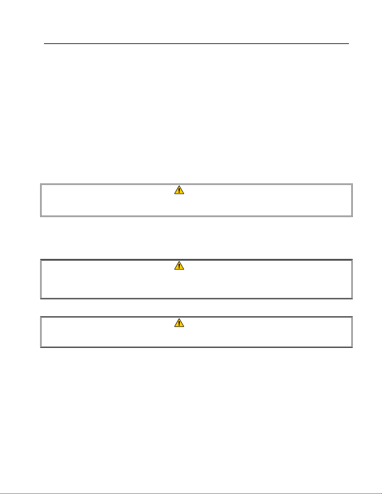
1. Open the doors of the filtration fryer cabinet.
Remove filter pan from the cabinet. Uncrate
fryers and remove the pallet supports. Install
ramps and slowly roll the fryer(s) off the pallets.
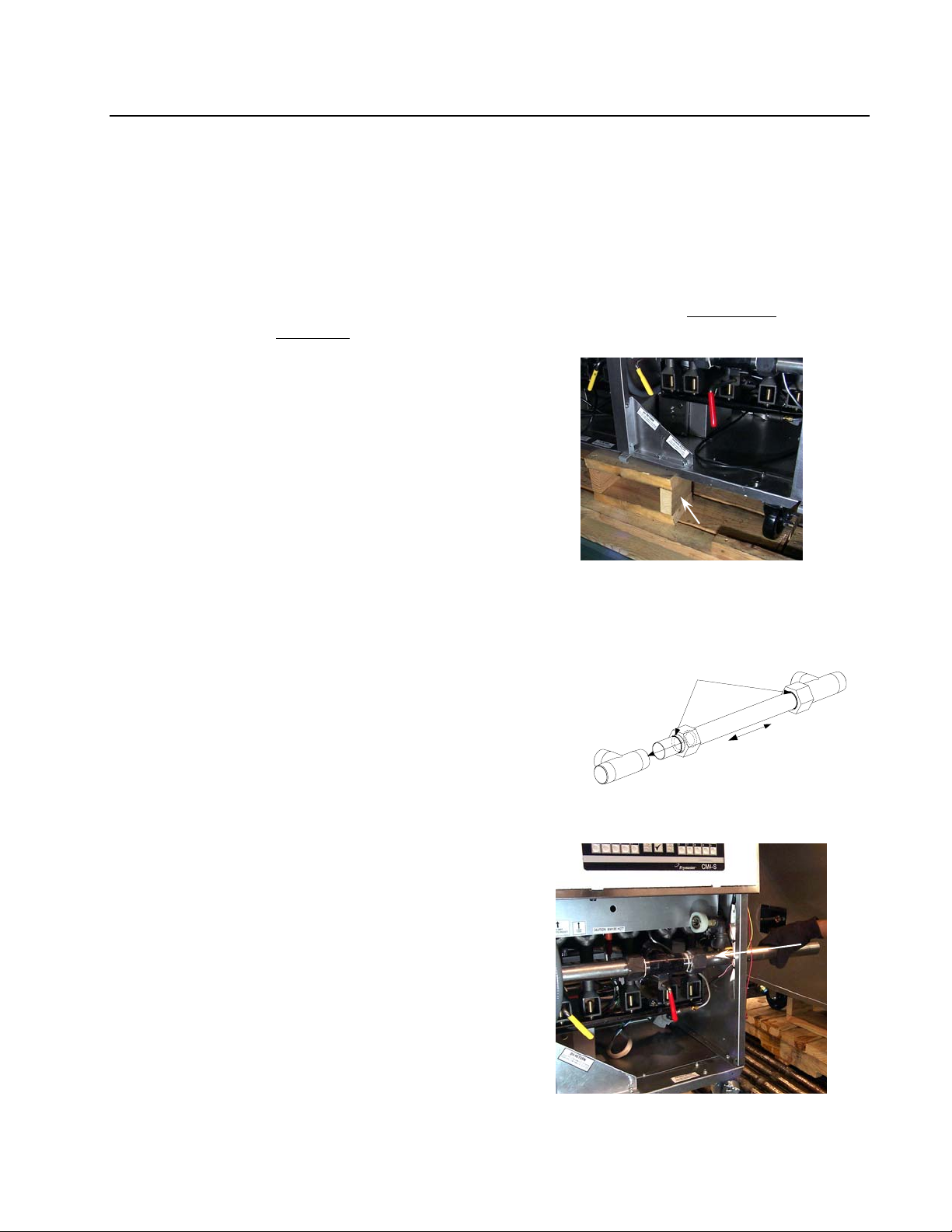
2. Remove door from fryers to be connected by
lifting the door upward and removing the door
pin from the bottom hinge. Remove slip-nuts
from drain-tees on fryers being connected,
lubricate O-rings with vegetable oil and install
on drainpipe (Fig. 2). Use care not to damage
the slip-nut O-rings when installing slip-nut on
drainpipe. Insert the drainpipe into the fryer
drain-tee (Fig. 3). Screw slip-nut onto the tee
but do not tighten at this time. Position fryers
being connected within 6 inches of each other,
near the permanent installation area. Guide the
drainpipe through the opposite fryer cabinet
opening as the cabinets are positioned.
NOTE: When the slip nuts are tightened, the
"blue" marks on each end of the drainpipe
should align to the outside edge of each slip
nut.
(where applicable).
Figure 1. Remove pallet supports (arrow)
before removing fryers from pallets.
Properly align th e drainpipe evenly between the
two drain-tees using the "blue" marks on the tube
ends to prevent le aks and/or blocked drain
Figure 2. Slip-nut/drainpipe detail.
valves.
3-1
Figure 3. Insert drainpipe section into fryer
drain-tee before pushing fryers together
(arrow). Do this as required for all cabinets
being assembled.
Page 15

FRYMASTER FPD65 SERIES GAS FRYERS
CHAPTER 3: INSTALLATION
3.1 Installing the Fryer (cont.)
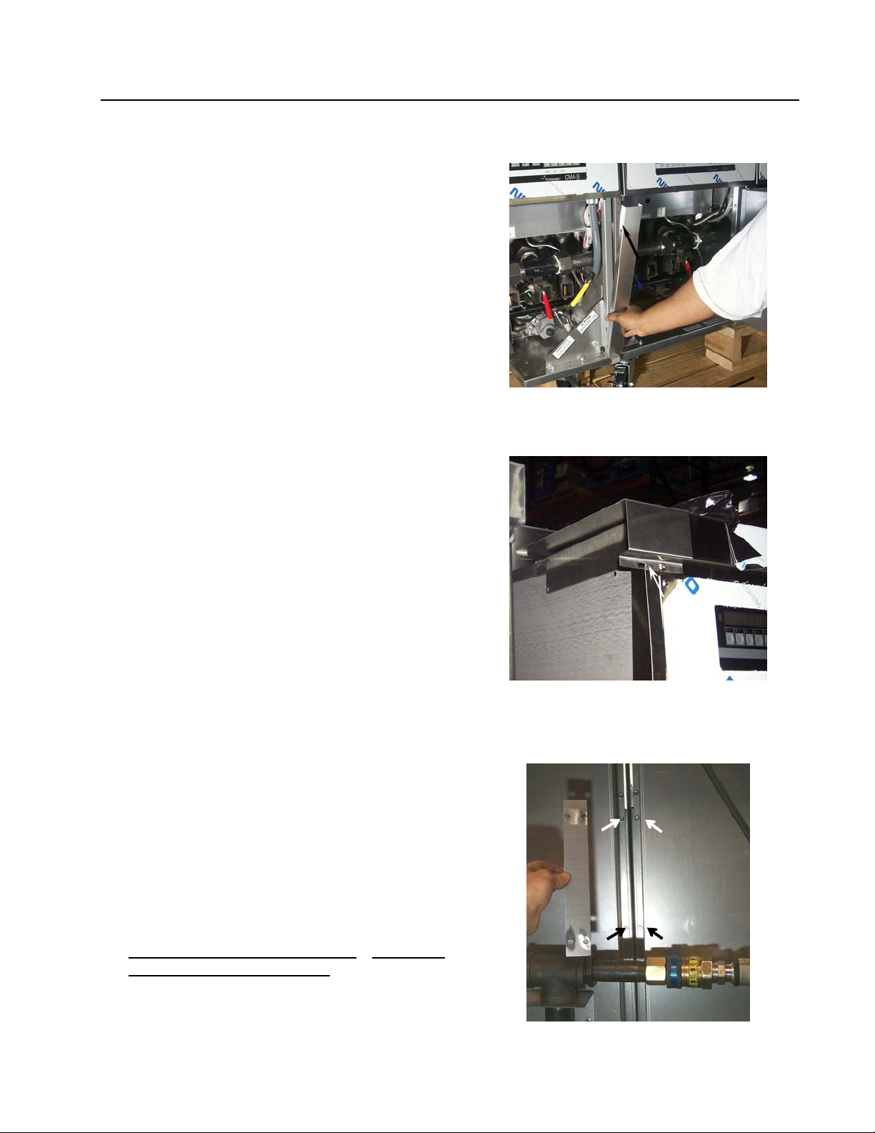
3. Connect red/white or red/yellow wires (Figure 4,
left) between fryer sections being assembled
(Figure 4, right, arrow). Oil-return will not
operate properly if these wires are not connected.
NOTE: On systems shipped in three or more
sections, additional wiring between cabinets
will exist. Ensure all wires are connected
before completing cabinet assembly.
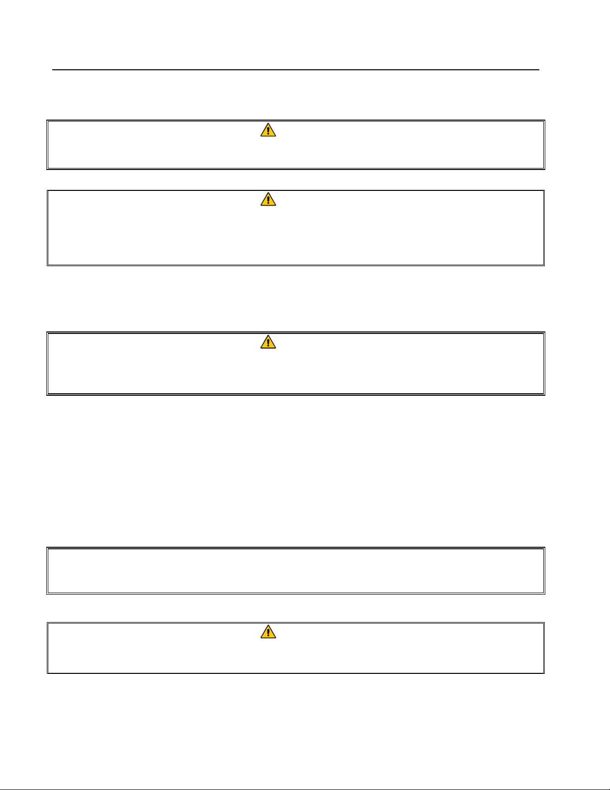
4. Remove the lower back panel-strips on fryers
being assembled to gain access to the oil return
and rinse-line connections (Figure 5, arrows).
Back removal may not be required on some
systems.
5. Slowly push the two cabinets together. Ensure
the drainpipe and slip-nut are aligned with the
drain-tee on the opposite fryer section. Ensure
the oil-return and rinse-hose connections (where
applicable) on each fryer section are aligned.
Ensure oil-return switch wires between cabinet
sections are not pinched when the cabinets are
brought together. Pull excess wire through the
opposite fryer side as the cabinets are brought
together. Secure excess wire inside cabinet with
a wire tie.
6. With the cabinets together, insert the drainpipe
into the opposite fryer drain-tee and position it
evenly between the fryers being connected.
Connect the oil-return and rinse-lines by
accessing the oil return union through the lower
fryer-back openings. Connect all fittings, but do
not tighten at this time.
7. Align the cabinet connection holes, front and
back (Figure 6, arrow). Connection hardware is
included in the accessories pack. Insert bolts and
install nuts, but do not tighten. If holes do not
align, use a 3/16" drill-bit and drill through the
misaligned hole.
8. Install the frypot joiner strip between cabinet
sections (Figure 7; also see factory-installed
strips on two-battery cabinet sections).
Figure 4. Oil return wires between sections
must be connected for oil-return operation.
Figure 5. Oil return and rinse-line (where
applicable) connections.
Figure 6. Cabinet connection locations
inside cabinet sections (front shown).
3-2
Figure 7. Install joiner strip(s) after fryers
are connected.
Page 16
FRYMASTER FPD65 SERIES GAS FRYERS
y
CHAPTER 3: INSTALLATION
3.1 Installing the Fryer (cont.)
9. Install the front connecting post on the connected
cabinets (Figure 8; see factory-installed posts on
two-battery fryer sections).
10. Complete installation of topcap battering strips
after the front connecting post has been installed
(Figure 9).
NOTE: Systems shipped in three or more
sections will require the installation of topcaps
and other components prior to installing
topcap-battering strips. See Topcap
Installation Instructions for these systems.
11. Install the rear connecting plate (Figure 10).
Remove four screws from the cabinet backs
(Figure 10, arrows), install connecting plate and
replace screws. Connection strips vary from
system to system.
12. At the fryer front: Tighten the drain manifold
slip-nuts. Install doors removed at the beginning
of assembly. At the fryer back: Tighten the oil-
return line and rinse-line (where applicable)
union(s).
13. Reinstall filter pan after fryer start-up has been
performed (boil-out, burner adjustment, etc.)
NEVER ALLOW WATER OR BOILOUT
SOLUTION INTO FILTER SYSTEM.
Check all connections for leaks.
components operate properly.
Ensure all
Figure 8. Installing front connecting post
on connected fryer sections.
Figure 9. Complete installation of topcap
battering strips (arrow) after installing
front connecting post(s) on connected
fr
ers.
Figure 10. Install rear connecting plate.
3-3
Page 17
FRYMASTER FPD65 SERIES GAS FRYERS
CHAPTER 3: INSTALLATION
3.1 Installing the Fryer (cont.)
DANGER
Fryers must be at room temperature and empty of oil during movement to avoid
damage and possible bodily injury.
DANGER
Hot shortening can cause severe burns. Avoid contact. Under all circumstances, oil
must be removed from the fryer before attempting to move it to avoid oil spills, and
the falls and severe burns that could occur. This fryer may tip and cause personal
injury if not secured in a stationary position.
3.2 Gas Connections
DANGER
Before connecting new pipe to this appliance the pipe must be blown out thoroughly
to remove all foreign material. Foreign material in the burner and gas controls will
cause improper and dangerous operation.
NATIONAL CODE REQUIREMENTS
This equipment is to be installed in compliance with the Basic Plumbing Code of the Building
Officials and Code Administrators International, Inc. (BOCA) and the Food Service Sanitation
Manual of the U.S. Food and Drug Administration.
This equipment is manufactured to use the type of gas specified on the rating plate attached to the
door. Connect equipment stamped "NAT" only to natural gas and that stamped "PRO" only to LP
(Propane) gas.
Notice
Installation shall be made with a gas connector that complies with national and local codes.
Quick disconnect devices, if used, shall likewise comply with national and local codes.
DANGER
The fryer MUST be connected to the gas supply specified on the rating and serial
number plate located on the back of the fryer door.
3-4
Page 18
FRYMASTER FPD65 SERIES GAS FRYERS
CHAPTER 3: INSTALLATION
3.2 Gas Connections (cont.)
DANGER
If gas odors are detected, the gas supply MUST be shut off at the main shut-off
valve. The local gas company or FASC should be contacted immediately to rectify
the problem.
A. The gas supply (service) line must be the same size or greater than the fryer inlet line. This
fryer system is equipped with three 1" (28 mm) female inlets (one inlet per two fryers). The
gas supply line must be sized to accommodate all the gas-fired equipment that may be
connected to that gas supply. Consult your contractor, gas company, supplier, or other
knowledgeable authorities.
Gas Types Number of Fryers
1 2 to 3 4 or more (*)
Natural Gas 3/4" (22 mm) 1" (28 mm) 1-1/4" (35 mm)
Propane Gas 1/2" (15 mm) 3/4" (22 mm) 1" (28 mm)
(*) When exceeding 18 feet for a configuration of more than four fryers, it is necessary to provide
a 1-1/4" (35 mm) rigid gas connection.
Recommended Gas Supply Line Sizes
DANGER
All connections must be sealed with a joint compound suitable for the gas being
used and all connections must be tested with a solution of soapy water before
lighting any pilots.
Never use matches, candles, or any other ignition source to check for leaks. If gas
odors are detected, shut off the gas supply to the appliance at the main shut-off
valve and immediately contact the local gas company or an authorized service
agency for service.
DANGER
"Dry-firing" your unit will cause damage to the frypot and can cause a fire. Always
ensure that melted shortening, cooking oil or water is in the frypot before firing the
unit.
B. Rigid Connections : Check any installer-supplied intake pipe(s) visually and clean threading
chips, or any other foreign matter before installing into a service line. If the intake pipes are
not clear of all foreign matter, the orifices will clog when gas pressure is applied. Seal pipe
joints with a sealant resistive to LP gas. When using thread compound on gas piping, use
very small amounts and only on male threads. Use a pipe thread compound that is not
affected by the chemical action of LP gases. DO NOT apply thread compound to the first
two pipe threads—doing so will cause clogging of the burner orifices and control valve.
3-5
Page 19

FRYMASTER FPD65 SERIES GAS FRYERS
CHAPTER 3: INSTALLATION
3.2 Gas Connections (cont.)
C. Manual shut-off valve : This gas service supplier-installed valve must be installed in the gas
service line ahead of the fryers in the gas stream and in a position where it can be reached
quickly in the event of an emergency.
D. Regulating Gas Pressure: The fryer and shut-off valve must be disconnected from the gas
supply during any pressure testing of the system.
1. External gas regulators are not normally required on this fryer. A safety control valve
protects the fryer against pressure fluctuations. If the incoming pressure is in excess of
½" PSI (3.45 kPa/35 mbar), a step-down regulator will be required.
DANGER
When pressure-testing incoming gas supply lines, disconnect the fryer from the gas
line if the test pressure is ½" PSI [3.45 kPa (14 inches W.C.)] or greater to avoid
damage to the fryer’s gas piping and gas valve(s).
E. Manifold Pressure: Your local service technician should check the manifold pressure with a
manometer.
1. Check the rating plate for specific manifold gas pressures. Natural gas units normally
require 4" W.C., and propane units normally require 11" W.C. gas pressure.
2. Double check the arrow forged into the bottom of the regulator body, which shows gas
flow direction. It should point downstream towards the fryers. The air vent cap is also
part of the regulator and should not be removed.
3. If a vent line from the gas pressure regulator is used, it should be installed in
accordance with local codes or in the absence of local codes, with the National Fuel
Gas Code, ANSI Z223.1-(latest edition).
WARNING
Use a diluted soap solution to find potentially dangerous gas leaks when making
new connections.
F. Regulators can be adjusted in the field, but it is recommended that they not be unless the part
is known to be out of adjustment or serious pressure fluctuations are found to exist and can
be solved no other way.
G. Only qualified service personnel should make adjustments to the regulators
.
H. Orifices: The fryer can be configured to operate on any available gas. The correct safety
control valve, appropriate gas orifices, and pilot burner are installed at the factory. While the
valve can be adjusted in the field, only qualified service personnel should make any
adjustments with the proper test equipment.
3-6
Page 20

FRYMASTER FPD65 SERIES GAS FRYERS
CHAPTER 3: INSTALLATION
3.2 Gas Connections (cont.)
I. Flexible Couplings, Connectors and Casters:
1. If the fryer is to be installed with flexible couplings and/or quick-disconnect fittings, the
installer must use a heavy-duty AGA design-certified commercial flexible connector of
at least 1" NPT (with suitable strain reliefs), in compliance with the Standard for
Connectors for Movable Gas Appliances, ANSI Z21.69-(latest edition) and Addenda
Z21.69a-(latest edition). Quick disconnect devices must comply with the Standard for
Quick-Disconnect Devices for Use with Gas Fuel, ANSI Z21.41-(latest edition).
WARNING
Do not attach accessories to this fryer unless fryer is secured from tipping.
Personal injury may result.
2. The fryer must be restrained by means independent of the flexible coupling or
connector in order to limit the movement of the fryer. Clips are located on the back
panel of the fryer for the attachment of restraints.
3. If disconnection of the restraint is necessary, this restraint must be reconnected after the
fryer has been returned to its originally installed position.
J. After hook-up, bleed the gas line of air to ensure that the pilot light will ignite quickly.
3.3 Adjustments/Adaptation To Different Gases
A. Proper operation of Frymaster/Dean gas fryers requires operator to inspect the following
adjustments in terms of:
1. Gas inputs and pressures.
2. Voltage and polarities of electrical power supplies.
B. Frymaster/Dean gas fryers are manufactured to use the type of gas and pressure specified on
the rating plate. When changing to a different gas, adaptation must be performed by
qualified personnel. Failure to use qualified personnel will void the Frymaster/Dean
warranty.
3-7
Page 21

FRYMASTER FPD65 SERIES GAS FRYERS
CHAPTER 3: INSTALLATION
3.3.1 Specifications
3.3.1.1 Adjustments to Different Gas Types
Gas Adjustments
Gas Type
Manifold Pressure†
Orifice Diameter
Burner Marking
Pilot Marking
* Gas pressure may vary per fryer model and altitude. Check the rating plate for specific
gas pressures.
Natural LP
4" W.C.*/10 mbar* 11" W.C.*/27.5 mbar*
Model Specific Model Specific
None None
26N (P/N 810-0811) 16LP (P/N 810-2400)
NOTE: Outlet gas pressure must be adjusted strictly within the above requirements 5 to 10 minutes
after the appliance is operating.
† For controls and adjustments, please refer to the "gas valve" illustration on page 3-9. (Pilot Flame
Adjustment: Turn the pilot adjustment screw clockwise/counter-clockwise until the desired flamevolume is achieved.)
3.3.2 Gas Conversion Procedures
DANGER
This appliance was configured at the factory for a specific type of gas. Converting
from one gas type to another requires the installation of specific gas-conversion
components.
Switching to a different type of gas without installing the proper conversion
components may result in fire or explosion. NEVER ATTACH THIS APPLIANCE TO A
GAS SUPPLY FOR WHICH IT IS NOT CONFIGURED!
Conversion of this appliance from one type of gas to another should only be
performed by qualified, licensed, and authorized installation or service personnel, as
defined in Section 1.6 of this manual.
3-8
Page 22

FRYMASTER FPD65 SERIES GAS FRYERS
CHAPTER 3: INSTALLATION
3.3.2 Gas Conversion Procedures (cont.)
Contact factory with the following information when performing conversions:
• Fryer Serial Number
• Fryer Model Number
• Gas Type
• Operating Altitude
Conversions can only be executed by qualified, factory-authorized personnel.
Pilot pressure adjustment
(remove cover screw to access)
Pressure flow adjustment
(remove cover screw to access)
Typical gas valve
Regulator Vent
ON/OFF Gas-Cock KnobPilot gas supply connection.
3.4 Electrical Connections
The fryer when installed must be electrically grounded in accordance with local codes, or in the
absence of local codes, with the National Electrical Code, ANSI/NFPA 70-(latest edition).
DANGER
This fryer is equipped with three-prong (grounding) plugs for protection against
electrical shock and must be plugged directly into a properly grounded, three-prong
receptacle. DO NOT CUT, REMOVE, OR OTHERWISE BYPASS THE GROUNDING
PRONGS ON THESE PLUGS!
The rating plate and wiring diagram are located inside the front door. The fryer is equipped with a
120VAC single-phase 60-hertz system (Domestic), or 230VAC single-phase 50-hertz system
(International/CE). Do not cut or remove the ground prong from any of the power cord plugs. Do
not attempt to use the fryer during a power outage.
DANGER
This appliance requires electrical power for operation. Place the gas control valve in
the OFF position in case of a prolonged power outage. Do not attempt to operate
this appliance during a power outage.
3-9
Page 23

FRYMASTER FPD65 SERIES GAS FRYERS
CHAPTER 4: FRYER OPERATIONS
4.1 Initial Start-up
WARNING
The on-site supervisor is responsible for ensuring that operators are made aware of
the inherent hazards of operating a hot oil frying system, particularly the aspects of
system operation, oil filtration, draining and cleaning procedures.
Cleaning: New units are wiped clean with solvents at the factory to remove any visible signs of dirt,
oil, grease, etc. remaining from the manufacturing process, then coated lightly with oil. Before any
food preparation, wash thoroughly with hot, soapy water to remove any film residue and dust or
debris then rinse out and wipe dry. Also wash any accessories shipped with the unit. Close the drain
valve completely and remove the crumb screen covering the heating tubes. Ensure the screws
holding the thermostat and high-limit control sensing bulbs into the frypot are tight.
Do not bang fry baskets or other utensils on the fryer’s joiner strip. The strip is
present to seal the joint between the frypot. Banging fry baskets on the strip to
dislodge shortening will distort the strip, adversely affecting its fit. It is designed for
Typical high-limit/sensor probe locations and mounting hardware.
WARNING
a tight fit and should only be removed for cleaning.
DANGER
Never operate this appliance with an empty frypot. The frypot must be filled with
water or cooking oil/shortening before lighting the burners. Failure to do so will
damage the frypot and may cause a fire.
WARNING
When checking for burner ignition or performance, do not get too close to the
burners. Slow ignition can cause possible flashback, increasing the potential for
facial and body burns.
4-1
Page 24

FRYMASTER FPD65 SERIES GAS FRYERS
CHAPTER 4: FRYER OPERATIONS
4.1.1 Pilot Lighting Procedures, Electronic Ignition Systems
Initial Pilot Lighting: All Frymaster/Dean fryers are tested, adjusted and calibrated to sea level
conditions before leaving the factory. Adjustments to assure proper operation of pilot may be
necessary on installation to meet local conditions, low gas pressure, differences in altitude and
variations in gas characteristics. These adjustments correct possible problems caused by rough
handling or vibration during shipment, and are to be performed only by qualified service personnel.
These adjustments are the responsibility of the customer and/or the dealer and are not covered by the
Frymaster/Dean warranty.
The inlet pipe at the lower rear of the fryer brings incoming gas to the pilot safety control valve, then
to the pilot and main burners. The pilot is located high in the cabinet center, at the base of the
frypot.
WARNING
Never use a match or taper to light pilot on this ignition system.
1. Turn gas "ON".
2. Turn electric power "ON" with the appropriate rocker switch or controller/computer.
3. The ignition module will energize the pilot gas supply and the ignitor. The ignitor spark will
ignite the pilot gas. The presence of the pilot flame is then proved by a flame sensor, which
sends a signal to the main gas supply, opening the valve. The operating thermostat or
computer/controller controls the fryer after ignition.
WARNING
In the event of prolonged power failure, the ignition module will shut down and lock
out the system. Turn the unit power "OFF" and them back "ON" after power has
been re-established.
4. If the pilot flame fails, the ignition module will shut down and lock out the system. To restart,
turn the electric power "OFF", wait approximately 5 minutes for the system to recycle itself, then
turn the power "ON" again. Repeat Steps 1-3.
4-2
Page 25

FRYMASTER FPD65 SERIES GAS FRYERS
CHAPTER 4: FRYER OPERATIONS
4.2 Boil-Out Procedure
DANGER
Never leave the fryer unattended during the boil-out process. If the boil-out solution
boils over, turn the fryer off immediately and let the solution cool for a few minutes
before resuming the process. To lessen the chance of boil over, turn the fryer’s gas
valve knob to the PILOT position occasionally.
WARNING
Do not drain boil-out solution into a shortening disposal unit, a built-in filtration unit,
or a portable filter unit. These units are not intended for this purpose, and will be
damaged by the solution.
DANGER
Remove all drops of water from the frypot before filling with cooking oil or
shortening. Failure to do so will cause spattering of hot liquid when the oil or
shortening is heated to cooking temperature and may cause injury to nearby
personnel.
A. Pour cleaning solution into the frypot and add water to the bottom OIL LEVEL line scribed
in the back of the frypot.
B. Operating thermostat-equipped fryers: Set dial/temperature controller to 225°F (107ºC), just
above that of boiling water.
C. Filtration/Boil-Mode equipped fryers: Turn fryer power switch to "ON". Press the fryer-
reset switch (if applicable). Turn the boil-out switch "ON".
CAUTION
If the pilot and main burner go out, the fryer(s) MUST be left completely shut down at
least 5 minutes before lighting.
D. The main burner will ignite.
E. When the solution nears boiling point, reset the temperature controller to 200°(93ºC).
F. The burners should shut off just as the water starts to boil.
CAUTION
Do not leave fryer unattended. The boil-out solution may foam and overflow if fryer is
left unattended. Press ON/OFF switch to the "OFF" position (Filtration/Boil-Mode
equipped fryers) or reduce temperature (Operating Thermostat equipped fryers) to
control this condition.
4-3
Page 26

FRYMASTER FPD65 SERIES GAS FRYERS
CHAPTER 4: FRYER OPERATIONS
4.2 Boil-Out Procedure (cont.)
G. The burners will heat the boil-out solution to a simmer. Simmer the solution for
approximately 45 minutes. Wearing protective gloves, scrub the sides of the frypot and the
tubes with the L-shaped Teflon brush, being careful not to disturb the temperature sensing
probes and the high-limit thermostat.
H. Do not allow the water level to decrease below the bottom OIL LEVEL line in frypot during
boil-out operation.
WARNING
Water or boil-out solution MUST not be allowed to drain into the filter pan or filter
system. Irreversible damage will result if water is allowed into the system.
I. After boil out is complete, turn the computer off. Drain the solution from the frypot. Place
a metal stockpot of sufficient size to safely hold the entire contents of the frypot under the
drain port to collect the water/boil-out solution. Do not allow water or boil-out solution to
drain into the filter pan. The filter pump is not designed for water operation, and will be
irreparably damaged (see warning statement above).
J. Close the drain, add fresh water (without boil-out solution) and wash all surfaces of the
frypot. Drain again.
K. Refill the frypot with fresh water and vinegar to neutralize any residual boil-out solution.
Wash all surfaces of the frypot. Drain completely and wipe down all surfaces of the frypot
to completely remove all water.
Computer-equipped fryers: See computer manual for boil-out programming and follow the
above procedures for boil-out.
DANGER
Do not go near the area directly over the flue outlet while the fryer is operating.
Always wear oil-proof, insulated gloves when working with the fryer filled with hot
oil.
Always drain hot oil into a metal stockpot of sufficient size to safely hold the entire
contents of the frypot.
4-4
Page 27

FRYMASTER FPD65 SERIES GAS FRYERS
CHAPTER 4: FRYER OPERATIONS
4.3 Final Preparation
WARNING
NEVER set a complete block of solid shortening on top of heating tubes. To do so
will damage the heating tubes and frypot, and void the warranty.
4.3.1 Filling Fryer with Cooking Oil/Shortening
A. When using a liquid shortening (cooking oil), fill the fryer to the bottom OIL LEVEL line
scribed into the back of the frypot.
B. When using a solid shortening, cut it into small pieces and pack it below the heat tubes,
between the tubes and on top of the tubes, leaving no air spaces around the tubes. Do not
disturb or bend the probe sensing bulbs.
C. Press the computer on/off switch to "ON". The burners will initially operate in the MELT
CYCLE mode until the shortening reaches 180°F. It will then automatically switch to
normal operation.
D. When the frypot is filled and the shortening is melted, carefully replace the crumb screen
over the heat tubes. Wear oil-proof insulated gloves to avoid the potential for burn injury
when placing crumb screen in frypot.
For additional computer instructions, see computer manual that came with
frying system.
4-5
Page 28

FRYMASTER FPD65 SERIES GAS FRYERS
CHAPTER 5: FILTRATION OPERATION
WARNING
Drawings and photos used in this manual are intended to illustrate operational,
cleaning and technical procedures and may not conform to on-site management
operational procedures.
5.1 General
Frymaster FPD65 Series gas fryer filter systems come equipped with a filter-leaf assembly, which
eliminates the need for filter paper. Filter powder is used to enhance the filtration process.
5.2 Filtration Preparation
On initial installation and before each use, remove all loose parts from the filter, wash the filter pan
and all accessories in hot, soapy water and dry thoroughly.
5.2.1 Assembling the Filter
Frymaster FPD65 Series filter systems incorporate a filter-leaf assembly, in which a fine mesh
screen is used to filter impurities and debris from the oil. The oil is pumped through the screen and
then returned to the frypot.
Assemble the filter pan as follows (see illustration below):
1. Filter pan assembly.
2. Filter-leaf assembly.
3. Crumb screen.
4. Front filter pan cover.
5. Rear filter pan cover.
5
4
2
3
1
5-1
Page 29

FRYMASTER FPD65 SERIES GAS FRYERS
CHAPTER 5: FILTRATION OPERATION
5.2.1 Assembling the Filter (cont.)
Assemble the filter as follows:
1. Remove the filter pan covers.
2. Place the filter leaf assembly in the bottom of
the filter pan, ensuring the filter disconnect is
properly placed in the filter pan slot. Support
the screen assembly by holding the supply
pipe during installation.
3. Ensure the filter screen lies flat in the bottom
of the pan and the supply connection bracket
is properly positioned in the pan slot before
proceeding.
Filter pan with covers removed.
The bracket fits into a slot in the pan.
Filter leaf properly positioned in filter pan.
5-2
Page 30

FRYMASTER FPD65 SERIES GAS FRYERS
CHAPTER 5: FILTRATION OPERATION
5.2.1 Assembling the Filter (cont.)
4. Place the crumb tray in filter pan.
5. Replace the pan covers and install the filter
pan into the cabinet. Ensure the connections
are fully engaged. Ensure the filter pan
opening is directly under the drain tubes to
avoid splashing hot oil. The fryer is ready for
filtering.
Crumb screen placement in filter pan.
The filter pan slides under the
fryer (above), connecting with a
slip fitting (right). The slip fitting
is located between the drain
tubes (above, arrow).
5-3
Page 31

FRYMASTER FPD65 SERIES GAS FRYERS
CHAPTER 5: FILTRATION OPERATION
5.2.2 Disassembling/Assembling and Cleaning an Optional Filter Leaf
Follow these steps to clean a leaf-style filter:
2
4
1
1
3
Filter Leaf Disassembly/Assembly
Grasp the seal frame near each corner at the locking tab (1) and pull frame apart The seal frame will
separate into two pieces. Separate the top and bottom screens (2 & 3) and remove the grid (4).
Assemble in reverse order.
5-4
Page 32

FRYMASTER FPD65 SERIES GAS FRYERS
CHAPTER 5: FILTRATION OPERATION
Cleaning the Filter Leaf Assembly
Clean the two seal frame pieces, screens and grid using a good quality degreaser and hot water from
a spray nozzle. The groove in the seal frame pieces can be cleaned with the edge of a Scotch-Brite
or similar cleaning pad.
At each scheduled boil out, disassemble the filter leaf as described in Section 5.7.1 and place in the
frypot filled with boil-out solution. Follow the boil-out procedure in Section 4.4.1, including placing
the filter leaf in the vinegar solution to neutralize boil-out residue, and clean water to rinse away
vinegar residue.
Allow all filter leaf components to air dry or thoroughly dry with paper towels.
5.3 Daily Filtration Operation
WARNING
Use caution and wear proper protective clothing. The oil to be filtered is at or near
350°F (177°C). Ensure all hoses are connected properly and drain handles are in
their proper position prior to operating any switches or valves. Failure to do this can
result in severe burns.
WARNING
Drawings and photos used in this manual are intended to illustrate operational,
cleaning and technical procedures and may not conform to on-site management
operational procedures.
5.3.1 General Overview
The filter pump is turned on only after the oil is brought to operating temperature and drained into
the prepared filter pan. The filter motor is then engaged and oil is drawn through the filter leaf
assembly and pumped back into the frypot. The frypot drain valve remains open during the filtering
process. The oil is cycled through the filter leaf assembly for approximately 10 minutes (see
computer section for specific instructions). At the end of 10 minutes, the drain valve is closed,
allowing the oil to pump back into the frypot. The pump should run for 15-30 seconds after bubbles
appear in the frypot to ensure all oil or shortening is pumped from the drain pan and the oil-return
lines. The frypot oil level should return to the top OIL LEVEL line. If not, add fresh oil or
shortening to obtain the proper level. Remember, the oil is at operating temperature during all
filtration procedures.
The filter pump can be activated with a manual On/Off switch located under the fryer control panel
if the oil-return, drain-flush or wand/dispose valves fail to activate the pump when opened. Contact
an authorized service technician immediately for repair.
Refer to specific store procedures for correct filter operation. Additional information can be found
in the computer section of this manual.
5-5
Page 33

FRYMASTER FPD65 SERIES GAS FRYERS
CHAPTER 5: FILTRATION OPERATION
5.3.2 Filtering Tools
Assemble tools to be used for filtering. These are supplied with the filter starter kit included with
the fryer/filter system:
• Frypot/Filter Brush– used to clean frypot and filter pan sides and bottom, heating tubes, and
to dislodge sediment during filtration or shortening change.
• Clean-Out Rod– used to dislodge heavy debris in the drain tube (when needed).
The following tools are not required, but are recommended:
• Measuring Cup– used to measure filter powder.
• Fine Mesh Skimmer– used to remove large debris.
Note: Prior to proceeding, put on safety goggles, neoprene gloves and heavy
vinyl apron.
NOTICE
Follow specific store procedures when filtering the fryer. In the event store
procedures are not available, the following instructions can be followed until specific
store procedures are obtained.
WARNING
Filter ONLY one frypot at a time. The filter pan is designed to hold the contents of
one frypot ONLY.
5-6
Page 34

FRYMASTER FPD65 SERIES GAS FRYERS
CHAPTER 5: FILTRATION OPERATION
5.4 Operating the Filter
5.4.1 Filter Operation
CAUTION
NEVER operate the filter unit unless cooking oil is at operating temperature [~350°F
(~177°C)].
1. Remove fry baskets from frypot. Prior to
filtering, skim any large debris from the oil
with the fine mesh skimmer. Use extreme
caution, as oil is at or near operating
temperature [~350°F (~177°C)]. Use a metal
scraper to gently remove debris from frypot
walls above shortening level.
2. Pour 12 ounces by volume of filter powder
into the vat. Carefully stir the powder into
the oil with the fine mesh skimmer.
3. Ensure the oil is at operating temperature
(~350°F/177°C). Open the fryer drain valve.
Allow the oil to drain into the filter pan. The
computer will display OPEN DRAIN.
Prior to filtering, skim any large debris from oil in
frypot.
Adding filter powder to vat prior to filtering.
Pull red handle to open drain valve and allow hot
shortening to drain into filter pan.
5-7
Page 35

FRYMASTER FPD65 SERIES GAS FRYERS
CHAPTER 5: FILTRATION OPERATION
5.4.1 Filter Operation (cont.)
4. When all the oil has drained from the frypot,
connect the hose-wand assembly to the
disconnect valve in the fryer cabinet. DO
NOT ACTIVATE FILTER PUMP UNTIL
THE HOSE HAS BEEN PROPERLY
CONNECTED. Ensure the hose-disconnect
is properly connected before proceeding.
Remove the frypot wire rack prior to rinsing
frypot.
5. Place the hose wand into the frypot being
filtered and activate the rinse valve by turning
the blue handle to "WAND" (where
applicable), or by pressing the manual bypass
switch (systems without oil disposal system).
The filter pump will activate and oil will start
flowing through the rinse hose.
6. Hold the wand inside the frypot at a 45-
degree angle while the rinse valve is opened.
7. Use the wand to rinse debris from the frypot
for approximately 3 minutes. At the end of 3
minutes, the computer display will alternate
from OPEN DRAIN to the timed
countdown cycle (10 minutes). Turn the blue
handle or the manual bypass switch to "OFF",
and then close the drain valve (red handle).
Disconnect and drain the hose of all
shortening or oil. Hang hose upright to
ensure no shortening remains in hose.
Hose/wand disconnect properly connected to
disconnect valve in fryer cabinet (orientation of
disconnect may vary according to system).
After the hose wand end is properly positioned in
the frypot, activate the filter pump by turning the
blue handle to "WAND" (where applicable).
Use the wand to rinse debris from the frypot into
the filter pan. Maintain a firm grip on the wand
handle at all times.
5-8
Page 36

FRYMASTER FPD65 SERIES GAS FRYERS
CHAPTER 5: FILTRATION OPERATION
5.4.1 Filter Operation (cont.)
8. Begin the filtering process by pulling the
yellow handle to open the oil-return valve
(this activates the filter pump automatically).
9. Oil will begin to pump from the filter pan
into the frypot. Allow the oil to circulate
through the frypot for the remainder of the
timed countdown (approximately 10
minutes). This process is known as
"polishing".
10. The computer will display FILL at the end
of the timed countdown. Replace the frypot
grid rack. Close the red drain valve handle to
begin refilling the frypot.
Begin the filtering process by pulling yellow handle
to open oil return valve. Leave the drain valve
(red handle) open during the filtering process.
Polishing the oil removes suspended particles,
which increases the life of the oil.
When the computer displays FILL, close the
drain valve to begin refilling the frypot.
5-9
Page 37

FRYMASTER FPD65 SERIES GAS FRYERS
CHAPTER 5: FILTRATION OPERATION
5.4.1 Filter Operation (cont.)
11. After all shortening is pumped back into the
frypot, bubbles will form, indicating air in the
oil return lines. Allow the shortening to
bubble for 15-30 seconds to ensure all
shortening is cleared from the return lines.
An audible alarm will sound, indicating that
the frypot is full. Push the yellow handle to
close the oil return valve and deactivate the
filter pump.
12. If the shortening level is low, add fresh
shortening until the level is at the top OIL
LEVEL line (the shortening is at operating
temperature).
13. Do not allow crumbs to accumulate in the
crumb tray. The crumb tray MUST
be
emptied into a fireproof container at the end
of frying operations EACH day.
Allow the oil to bubble for 15-30 seconds to
ensure evacuation of all oil in the return lines.
Add fresh shortening until the level is at the top
OIL LEVEL line. DO NOT OVERFILL THE
FRYPOT.
Empty the filter pan crumb tray into a fire-proof
container at the end of frying operations each day.
DO NOT ALLOW CRUMBS TO ACCUMULATE IN
TRAY.
5-10
Page 38

FRYMASTER FPD65 SERIES GAS FRYERS
CHAPTER 5: FILTRATION OPERATION
5.4.1 Filter Operation (cont.)
14. OPTIONAL EQUIPMENT: Drain-flushes
are included on 5-battery and larger
Frymaster FPD65 Series fryers. After
filtering frypot farthest from the filter system
for 10 minutes, close the oil return valve to
stop the filtering process. Do not refill the
frypot. Close the drain valve (red handle) on
the frypot being filtered. Ensure all other
valves (red and yellow handles) are closed.
Pull the blue handle to open the flush valve
(6-battery systems have two). After the drain
line is clear of sediment (approximately 2
minutes), push the blue handle to close flush
valve. Open the oil-return valve (yellow
handle) to refill the frypot.
15. OPTIONAL EQUIPMENT: Shortening
Disposal: Follow store procedures when
disposing of spent shortening. Ensure the
Shortening Disposal System is properly
connected and working properly before
proceeding. Turn the blue handle on the
wand/dispose valve to "DISPOSE" to start
the disposal process. Turn the blue handle to
"OFF" when the disposal process for that
frypot is complete.
Left drain-flush handle location (arrow) for frypot
#6.
Blue handle in "DISPOSE" position. Turn handle
to "OFF" after spent shortening is disposed of.
DANGER
The crumb tray in fryers equipped with a filter system must be emptied into a
fireproof container at the end of frying operations each day. Some food particles
can spontaneously combust if left soaking in certain shortening material.
WARNING
Do not bang fry baskets or other utensils on the fryer’s joiner strip. The strip is
present to seal the joint between the frypots. Banging fry baskets on the strip to
dislodge shortening will distort the strip, adversely affecting its fit. It is designed for
a tight fit and should only be removed for cleaning.
5-11
Page 39

FRYMASTER FPD65 SERIES GAS FRYERS
CHAPTER 6: PREVENTATIVE MAINTENANCE
6.1 General
DANGER
Never attempt to clean the fryer during the cooking process or when the frypot is
filled with hot oil/shortening. If water comes in contact with oil/shortening heated to
cooking temperature, it will cause spattering of the oil/shortening, which can result
in severe burns to nearby personnel.
Any equipment works better and lasts longer when maintained properly and kept clean. Cooking
equipment is no exception. Frymaster FPD65 Series gas fryers should be kept clean during the
working day, and thoroughly cleaned at the end of each day. Below are recommendations for daily,
weekly and periodic preventative maintenance.
6.1.1 Daily
WARNING
Use a commercial grade cleaner formulated to effectively clean and sanitize food-
contact surfaces. Read the directions and precautionary statements for use.
Particular attention must be paid to the concentration of cleaner and the length of
time the cleaner remains on the food-contact surfaces.
A. Remove and wash all removable parts.
B. Clean all exterior surfaces of the cabinet. Do not use cleaners, steel wool, or any other
abrasive material on stainless steel.
C. Filter the cooking oil and replace if necessary. The oil should be filtered more frequently
when under heavy use.
D. Clean filter pan, as well as, crumb tray as discussed on page 5-9.
6.1.2 Weekly
A. Completely drain the oil from the fryer into a metal stockpot of sufficient size to safely hold
the entire contents of the frypot for disposal. Do not use a glass or plastic container.
B. Clean the frypot by following boil-out procedures in Chapter 4.2.
WARNING
Never allow water to boil down and expose the heating tubes. Frypot damage will
result.
6-1
Page 40

FRYMASTER FPD65 SERIES GAS FRYERS
CHAPTER 6: PREVENTATIVE MAINTENANCE
6.1.3 Periodic/ Annual
The fryer should be inspected and adjusted periodically by qualified service personnel as part
of a regular kitchen maintenance program.
Frymaster/Dean recommends that the fryer be inspected at least annually by a Factory
Authorized Service Technician as follows:
• Inspect fryer cabinet inside and out, front and rear, for excessive oil build-up and/or oil
migration. Verify that burners and associated components (i.e. gas valves, pilot assemblies,
ignitors, etc.) are in good condition and functioning properly. Inspect all gas connections for
leaks and ensure all connections are properly tightened.
• Verify that temperature and high-limit probes are properly connected, tightened and functioning
properly.
• Verify all component box components (i.e. computer/controller, relays, transformers, interface
boards, etc.) are in good condition and free from oil migration build-up and other debris. Inspect
component box wiring and ensure all connections are tight and all wiring is in good condition.
Ensure all safety features (i.e. drain safety switches, reset switches, etc.) are present and
functioning properly.
• Verify that frypot is in good condition and free of leaks. Verify that frypot tube diffusers are
present and in good condition (i.e. no visible deterioration or damage).
• Verify that all wiring and connections are tight and in good condition.
Built-in Filtration:
• Inspect all oil-return and drain lines for leaks and verify that all connections are tight.
• Inspect the filter pan for leaks and cleanliness. If there is a large accumulation of crumbs in the
crumb basket, advise the owner/operator that the crumb basket should be emptied into a fireproof
container and cleaned daily.
• Verify that all O-rings and seals (including those on quick-disconnect fittings) are present and in
good condition. Replace O-rings and seals if worn or damaged.
6-2
Page 41

FRYMASTER FPD65 SERIES GAS FRYERS
CHAPTER 6: PREVENTATIVE MAINTENANCE
6.1.3 Periodic/ Annual (cont.)
• Check filtration system integrity as follows:
− With the filter pan empty, place each oil return handle, one at a time, in the "ON" position.
Verify that the pump activates and that bubbles appear in the cooking oil/shortening of the
associated frypot.
− Close all oil return valves (i.e., place all oil return handles in the "OFF" position). Verify proper
functioning of each oil return valve by activating the filter pump using the lever on one of the oil
return handle microswitches. No air bubbles should be visible in any frypot.
− Verify that the filter pan is properly prepared for filtering, then drain a frypot of oil heated to
350°F (177°C) into the filter pan and close the frypot drain valve. Place the oil return handle in
the "ON" position. Allow all cooking oil/shortening to return to the frypot (indicated by bubbles
in the cooking oil/shortening. Return the oil return handle to the "OFF" position. The frypot
should refill in no more than 2 minutes and 30 seconds.
To ensure good fryer health and a safe environment, the fryer should be checked and adjusted
periodically by qualified service personnel as part of a regular kitchen maintenance program.
6.1.4 Stainless Steel Care
DANGER
DO NOT let water splash into the tank of hot oil. It will splatter and can cause severe
burns.
All stainless steel fryer cabinet parts should be wiped regularly with hot, soapy water during the day,
and with a liquid cleanser designed for stainless steel at the end of each day.
A. Do not use steel wool, abrasive cloths, cleansers or powders.
B. Do not use a metal knife, spatula or any other metal tool to scrape stainless steel! Scratches
are almost impossible to remove.
C. If it is necessary to scrape the stainless steel to remove any encrusted materials, soak the area
first to soften the deposit, then use a wood or nylon scraper only.
6-3
Page 42

FRYMASTER FPD65 SERIES GAS FRYERS
CHAPTER 7: TROUBLESHOOTING
7.1 General
DANGER
Hot cooking oil/shortening will cause severe burns. Never attempt to move this
appliance when filled with hot cooking oil/shortening or to transfer hot cooking
oil/shortening from one container to another.
DANGER
This equipment should be unplugged when servicing, except when electrical circuit
tests are required. Use extreme care when performing such tests.
This appliance may have more than one electrical power supply connection point.
Disconnect all power cords before servicing.
Inspection, testing and repair of electrical components should be performed by an
authorized service agent only.
The problems and possible solutions covered are those most commonly encountered. To
troubleshoot, perform the test set-up at the beginning of each condition. Follow each step in
sequence.
7.2 Pilot Burner Malfunction
A. Pilot will not ignite; no evidence of gas at pilot burner.
1. Check that gas valve is open and gas is present at the gas valve.
2. Check pilot burner orifice for dirt or lint.
3. Authorized Service Agent Only
contamination; blow out if necessary, then reinstall.
B. Pilot burner ignites but will not remain lit when gas valve manual knob is released.
1. Check that thermopile lead is properly connected at the terminal block on the gas valve.
2. Authorized Service Agent Only: Pilot flame may be too high or too low. Adjust pilot
flame adjustment screw so that pilot flame extends about 3/4-inch (19-mm) above the top
of the pilot burner.
: Remove pilot burner gas-supply line and check for
7-1
Page 43

FRYMASTER FPD65 SERIES GAS FRYERS
CHAPTER 7: TROUBLESHOOTING
7.2 Pilot Burner Malfunction (cont.)
3. Check all connections for cleanliness and security.
C. Pilot flame of proper size, but is unstable. Flame wavers and does not envelop the
thermopile completely at all times.
1. Check for drafts that might be caused by air conditioning equipment or make-up air
apparatus. Turn air-moving equipment off and recheck the pilot.
7.3 Main Burner Malfunctions
A. Main burner will not come "ON"; gas not detected at main burner.
1. Check that the gas valve is open.
2. Check that the pilot is ignited and is operating properly.
3. Authorized Service Agent Only
4. Authorized Service Agent Only: Check the combination gas valve and replace if
defective.
B. Main burner flames are small and appear lazy; shortening does not come up to temperature
quickly.
1. Authorized Service Agent Only: Check gas pressure at the pressure tap of the gas valve.
Use dial type or standard water-type U-gauge manometer. With burner in operation, the
pressure should be 4" W.C. (10 mbar) for natural gas, and 11" W.C. (27.5 mbar) for
propane. If not, remove the pressure regulator adjustment cover. Use screwdriver to
turn the adjusting screw for proper pressure. Replace cover, re-check pressure and reinstall pressure tap plug.
C. Signs of excessive temperature; shortening scorches and quickly becomes discolored.
1. Check operating thermostat. May be out of adjustment or calibration. Recalibrate if
necessary.
2. Check gas pressure as outlined above.
3. Shortening used is of inferior quality and/or shortening has been used too long. Replace
shortening.
4. Ensure frypot is clean when refilling with new shortening.
: Check the high-limit switch for continuity.
7-2
Page 44

FRYMASTER FPD65 SERIES GAS FRYERS
CHAPTER 7: TROUBLESHOOTING
7.3 Main Burner Malfunctions (cont.)
D. Fryer will not reach the temperature setting and/or runs erratically.
1. Incorrect location of sensor probe or defective temperature sensor.
2. Loose wiring/wire connection
E. Fryer shortening temperature cannot be controlled; fryer runs at high-limit temperature.
1. Defective temperature probe; Call Authorized Service Agent.
7-3
Page 45

FRYMASTER FPD65 SERIES GAS FRYERS
CHAPTER 7: TROUBLESHOOTING
7.4 Wiring Diagram, Main
IGN
HI TENSION
TR
SEN
WHT
SENSOR
TH
NO
NC
CND
MV/PV
MV
PV
SAFETY
BLU
BRN
WHT
DRAIN SWITCH
C
1
2
987
2
1
8051481A
IGNITER
GAS
VALVE
24 VAC
BLU
654321
BLU
789
21 4356
54321 9876 14131110 12 15
CM4-S COMPUTER
TO J2 COMPUTER INTERFACE BOARD
HI LIMIT
BLK
BLK
YEL
12V
RED
24V
YEL
YEL
RED
BLK
RED
YEL
RED
1291011
87654321
BLK
WHT
2
1
J3
910 1211
4132 5678
COMPUTER INTERFACE
GRD
SOUND
A
10
BOARD
5342 8976 1412 1311 15
TO CM4-S COMPUTER
1
J2
LINE VOLTAGE
WHT
GND
BLK
FUSE
FUSE
2
1
TRANSFORMER
WHT
BLU
LINE
BLK
BLU
WHT
WHT
BLU
LINE
BLU
BLK
WHT
SPEAKER
7-4
Page 46

FRYMASTER FPD65 SERIES GAS FRYERS
CHAPTER 7: TROUBLESHOOTING
7.5 Wiring Diagram, Filter
8051428A
NC
NO
COM
35C35C
OIL RETURN
RH ADD-ON(S)
OIL RETURN
31C
12
BY-PASS SWITCH
33C
NCNC
NONO
FRYER
OIL RETURN
33C
82C
86C
COM COM
OIL RETURN
LH ADD-0N(S)
SHOWN IN
OFF POSITION
MICRO SWITCH
9C
4
3
TRANSFORMER/RELAY ASSY
82C
8C
27C
12C
MOTOR
41C
120V
24V
T5T4T2
LOW VOLTAGE SH OWN
T3
T8
P2
LEADS T5 AND T8 ON THE MOTOR
FOR CHANGE OF ROTATION INTERCHANGE
P1
T4
30C
WHT
5 AMP-480V
CB
BLK
115V
INPUT
CIRCUIT
7 AMP-120V
CIRCUIT BREAKER
T5
HIGH VOLTAGE SHOWN
WHT#1
P2
T2
T3
T8
P1
BLK
7-5
Page 47

FRYMASTER FPD65 SERIES GAS FRYERS
CHAPTER 8: PARTS LIST
8.1 Cabinetry and Related Components
Typical Cabinetry Components
(FPD665 Shown)
21
23
20
24
19
10
18
11
17
22
25
15
16
14
12
5
8
13
4
6
7
9
2
1
3
8-1
Page 48

FRYMASTER FPD65 SERIES GAS FRYERS
CHAPTER 8: PARTS LIST
8.1 Cabinetry and Related Components (cont.)
ITEM PART # COMPONENT
1 810-0357 Caster, 5" Swivel – With Brake
2 810-0356 Caster, 5" Swivel – Without Brake
3 823-3248 Support, Caster- Channel Base
4 202-1182 Gusset, Side Panel- Left
5 201-1182 Gusset, Side Panel- Right
6 200-1463 Channel, Base- Front & Rear- 2-Battery (FPD565 & FPD665)
* 200-2493 Channel, Base- Front & Rear- 1-Battery (FPD565 Only)
7 200-1198 Channel, Base- UFF Filter
8 823-3352 Support, Caster- UFF Base
9 200-1493 Frame, Base Lower Plate- UFF
10 200-1611 Base, Upper- UFF
11 200-4241 Plate, Motor Support- Offset
12 200-2308 Post, Door- UFF Cabinet
13 200-1393 Channel, Lower Joiner
14 200-1471 Duct, Door Access
15 202-1299 Panel, Side- Painted- Right
16 201-4775 Panel, Inner- Left
17 202-4775 Panel, Inner- Right
18 201-4237 Panel, Inner UFF- Left
19 202-4237 Panel, Inner UFF- Right
20 201-1299 Panel, Side- Painted- Left
21 823-3826 Fluecap
22 200-3696 Back, Upper Structural (FPD665)
* 200-3694 Back, Upper Structural (FPD565)
* 200-1376 Bracket, Restraining
23 200-1425 Back, Lower Structural- Right & Left Cabinet
24 200-4238 Back, Lower Structural- Middle UFF Cabinet
25 210-3700 Hanger, Basket- 2-Battery
* Not Illustrated
8-2
Page 49

FRYMASTER FPD65 SERIES GAS FRYERS
CHAPTER 8: PARTS LIST
8.2 Doors, Topcaps and Related Components
FPD665 Shown
2
1
3
ITEM PART # COMPONENT
1 824-1183 Topcap, 4-Battery
* 824-1184 Topcap, 3-Battery
2 824-1185 Topcap, 2-Battery
3 824-0951 Wireway, Control Panel (Component Box: See Section 8.4 For
4 200-1301 Pin, Door
5 200-1185 Panel, Door- Inner
6 210-1424 Panel, Door- Outer
7 810-2105 Handle, Door- Chrome
8 809-0918 Screw, #10-24 x ½" (Use With 810-2105)
9 809-0191 Washer, ¼" Lock (Use With 810-2105)
10 810-0066 Magnet, Door Catch- All Doors Except Filter
* 810-1105 Magnet, Door Catch- Filter Cabinet Doors
* 200-3663 Plate, Door Magnet (Use Where Magnet Contacts Stainless Steel)
11 809-0266 Screw, #10 x ½"
12 810-0179 Plug, Access (Handle Screws)
13 200-1675 Hinge, Lower Bracket- Door
* 809-0413 Spacer, Nylon- Lower Hinge/Door Pin
* Not Illustrated
13
4
Electronic Components)
11
12
10
9
8
5
7
6
8-3
Page 50

FRYMASTER FPD65 SERIES GAS FRYERS
CHAPTER 8: PARTS LIST
8.3 Frypots, Burners and Related Components
28
29
30
1
2
26
25
24
27
23
22
18
19
21
17
20
5
16
8
4
15
11121314
3
6
7
9
10
8-4
Page 51

FRYMASTER FPD65 SERIES GAS FRYERS
CHAPTER 8: PARTS LIST
8.3 Frypots, Burners and Related Components (cont.)
ITEM PART # COMPONENT
1 823-3948 Frypot- S/S- 65 Series
2 210-5170 Diffuser, Burner Tube
3 810-2150 Burner, Right
4 810-2149 Burner, Center
5 810-2151 Burner, Left
* 200-2738 Bracket, Burner Mounting
* 200-2746 Shield, Burner Heat
6 200-1615 Bracket, Manifold Mounting
7 809-0822 Bolt, ¼-20 x ½" Hex Head
8 809-0823 Nut, Nylock- ¼-20
9 810-2138 Valve, Trailing Pilot
10 813-0642 Tee, 1/8" NPT
11 813-0705 Plug, Brass- 1/8" Square Head
12 813-0643 Nipple, 1/8" NPT x Close BM
13 810-2050 Orifice, Natural- #44 (2.18 mm)
* 810-2324 Orifice, LP- #53 (1.40 mm)
14 823-3617 Manifold, Gas
15 807-3628 Valve, Gas- LP-24V, Honeywell
* 807-3552 Valve, Gas- Natural-24V, Honeywell
16 813-0174 Union- ¾" NPT BM
17 813-0635 Nipple, ¾ NPT x 2-½" BM
18 813-0066 Elbow- ¾" NPT 90° BM
19 813-0743 Nipple, ¾ NPT x 3-½" BM
20 813-0165 Elbow, Street- ½" NPT 90° BM
21 813-0670 Nipple, ½ NPT x 19" BM (Measure To Confirm Length)
* 813-0585 Nipple, ½ NPT x 20-½" BM (Measure To Confirm Length)
* 813-0737 Nipple, ½ NPT x 21" BM (Measure To Confirm Length)
22 810-2043 Clamp, Pipe- ½"
23 809-0805 Bolt, Pipe Clamp- ¼-20 x ½" Hex
* 200-1450 Bracket, Gas-Supply Clamp Support (UFF-Equipped Systems)
24 807-1553 Burner, Pilot- LP- Electronic Ignition
* 807-1311 Burner, Pilot- Natural- Electronic Ignition
* 807-1310 Sensor, Flame
25 810-0703 Gas Line, Main Pilot Supply- ¼ x 17-½"
* 810-0705 Gas Line, Main Pilot Supply- ¼ x 23"
26 810-2155 Burner, Trailing Pilot- LP
* 810-2032 Burner, Trailing Pilot- Natural
27 812-1544 Gas Line, Trailing Pilot Supply- ¼ x 12" (Not For Main Pilot)
28 106-2634SP
* 200-4086 Shield, Flue Heat
* 200-4087 Front, Flue Box
* 200-4088 Rear, Flue Box
* 200-3649 Deflector, Flue
29 810-2524 Grid, Frypot- 65 Series
30 106-2897SP Cover, Frypot- 65 Series
* Not Illustrated
Flue Assembly, Complete
8-5
Page 52

FRYMASTER FPD65 SERIES GAS FRYERS
CHAPTER 8: PARTS LIST
8.4 Component Box Components
1
ITEM PART # COMPONENT
1 823-3242 Control Box (Inside Non-Filter Fryer Cabinets)
2 210-1364 Plate, Face (For Item #1)
3 200-1322 Bracket, Spark Module
4 200-1326 Cover, Spark Module
5 807-3563 Module, Ignition (Spark)
* 807-1315 Cable, Ignition Module
6 806-4549 Board, Interface
7 807-0833 Relay, 12VDC 5A 1PDT (Latching)
8 807-0855 Transformer, 120VAC 50/60 Hz -12V 20VA
9 807-0800 Transformer, 120VAC 50/60 Hz -24V 50VA
10 807-1321 Fuse Holder, Buss
* 807-3750 Fuse, 5A
11 807-3580 Switch, Rocker- Manual Filter Power
12 807-3577 Breaker, Circuit- 7-Amp (115VAC Circuits)
* 807-3538 Breaker, Circuit- 5-Amp (230VAC Circuits)
13 807-3680 High-Limit Thermostat- Manual Reset 450° F (Non-CE Only)
14 806-7179 Device, Sound
15 200-2052 Bracket, Sound Device
16 807-3611 Relay, Filter- 24VAC Coil 24A
17 106-1541SP Probe, Temperature- Computer
18 806-8305 Computer, CM4-S- With Bezel Generic (Segmented Programming)
106-3028 Computer, CM4-S- With Bezel Church’s Only (Segmented. Prog.)
* 823-3433 Bezel, Computer
* Not Illustrated
3
17
4
16
5
2
13
12
15
11
10
14
6
7
8
9
CM4-S
18
8-6
Page 53

FRYMASTER FPD65 SERIES GAS FRYERS
CHAPTER 8: PARTS LIST
8.5 Filter Pan and Related Components
12
11
10
9
ITEM PART # COMPONENT
1 823-4109 Pan, Filter
2 810-2141 Caster, Filter Pan- 2"
3 809-0823 Nut, Nylock- ¼-20
4 810-2350 Leaf, Filter- 14-½ x 22-½"
5 810-2583 Fitting, Bottom- Filter Leaf
6 810-2582 Fitting, Top- Filter Leaf
* 803-0002 Powder, Filter- Box (Filter Magic- 100 1-Cup Applications)
7 823-4112 Tube, Suction
* 813-0679 Plug, Suction- 1/8" S/S Square Head
8 823-3872 Screen, Crumb
9 823-3178 Cover, Filter Pan- Front
10 210-1592 Cover, Filter Pan- Rear
11 810-2105 Handle, Pan Cover- Chrome
* 809-0918 Screw, #10-24 x ½" (Use With 810-2105)
* 809-0191 Washer, ¼" Lock (Use With 810-2105)
12 200-2713 Bracket, Slide Rail
13 210-1180 Insert, Slide Rail Bracket
14 823-3347 Rail, Slide
* Not Illustrated
6
5
1314
1
2
3
7
4
8
8-7
Page 54

FRYMASTER FPD65 SERIES GAS FRYERS
CHAPTER 8: PARTS LIST
8.6 Oil-Drain Components
22
20
19
18
17
16
15
21
23
5
6
4
2
3
8
7
Typical Drain Components
(FPD665 Shown)
1
14
9
13
12
10
11
8-8
Page 55

FRYMASTER FPD65 SERIES GAS FRYERS
CHAPTER 8: PARTS LIST
8.6 Oil-Drain Components (cont.)
ITEM PART # COMPONENT
1 823-4189 Pipe, Drain- Right- D665 (With Oil Disposal System)
* 823-3441 Pipe, Drain- Right- D565 (No Oil-Disposal System)
2 813-0829 Elbow, Drain Pipe- 75°
3 809-0884 Nut, Slip Joint- 1-½"
4 816-0544 O-ring (Slip-Joint Nut)
5 200-1840 Drain Manifold Tube
6 813-0749 Tee, 1-½" NPT With Handle
7 813-0165 Elbow, Street- ½ x ½" 90°
8 810-1069 Flex Line, 5/8" x 29-½ " (Measure To Confirm Length)
9 810-1057 Flex Line, 5/8 x 13" (Measure To Confirm Length)
10 810-1668 Adapter, 5/8" O.D. x ½"- Male (Use With 810-1057 and 810-1069)
11 813-0062 Elbow, ½" NPT BM 90°
12 813-0096 Nipple, ½ x 6" NPT BM
13 813-0686 Bell Reducer, 1-½ x ½" NPT
14 813-0784 Drain Pipe, Left Side
15 106-1401 Bracket, Microswitch (Optional On Some Units)
16 200-1617 Washer, Drain Valve (Use Without Microswitch)
17 210-2029 Bracket, Activator- Microswitch
18 200-1940 Handle (Actuator), Drain Valve
* 823-3440 Handle, Push/Pull- Drain (With Cap)
* 809-0885 Washer, 3/8 x 1 x .083"
* 809-0843 Cotter Pin
* 816-0547 Cap, Vinyl-Red
19 807-2104 Microswitch (Optional On Some Units)
20 809-0842 Nut, Nylock- #4-40 (Microswitch To Bracket)
21 816-0220 Insulation, Microswitch
22 200-1257 Retainer, Nut
23 810-2127 Drain Valve, 1-½" Full Port (With Washers & Nut)
* Not Illustrated
Drain Valve Components
8-9
Page 56

FRYMASTER FPD65 SERIES GAS FRYERS
CHAPTER 8: PARTS LIST
8.7 Oil-Return Components
17
10
Typical Oil-Return Components
(FPD665 Shown)
ITEM PART # COMPONENT
1 813-0156 Plug, Pipe- Hex Head Extruded
2
813-0022 Nipple, ½" x Close NPT BM
813-0087 Nipple, ½ x 1-½" NPT BM
813-0298 Nipple, ½ x 2" NPT BM
813-0265 Nipple, ½ x 2-½" NPT BM
813-0460 Nipple, ½ x 3" NPT BM
813-0247 Nipple, ½ x 3-½" NPT BM
813-0251 Nipple, ½ x 4-½" NPT BM
813-0646 Nipple, ½ x 5" NPT BM
813-0742 Nipple, ½ x 5-½" NPT BM
813-0674 Nipple, ½ x 7-¼" NPT BM
813-0672 Nipple, ½ x 8" NPT BM
813-0673 Nipple, ½ x 8-½" NPT BM
813-0698 Nipple, ½ x 10-½" NPT BM
813-0515 Nipple, ½ x 12" NPT BM
813-0418 Nipple, ½ x 17" NPT BM
813-0670 Nipple, ½ x 19" NPT BM
* Not Illustrated
16
2
Rinse Hose Plumbing
(Optional)
Nipple, Pipe (Measure To Confirm Length Prior To Replacing;
Choose From Nipple Lengths Below)
2
10
5
6
2
8
7
9
4
12
Oil Disposal Plumbing
2
3
13
1
14
(Optional)
10
15
2
11
8-10
Page 57

FRYMASTER FPD65 SERIES GAS FRYERS
CHAPTER 8: PARTS LIST
8.7 Oil-Return Components (cont.)
ITEM PART # COMPONENT
3 813-0173 Union, ½" NPT BM
4 813-0003 Tee, ½" NPT BM
5 813-0165 Elbow, Street ½" NPT BM 90°
6 813-0051 Coupling, ½" NPT BM
7 813-0062 Elbow, ½" NPT BM 90°
8 810-1003 Valve, Ball- Three-Way ½" 180°
* 823-4234 Handle, Wand/Disposal
* 210-4239 Bracket, Wand/Disposal Handle
* 816-0549 Cap, Handle- Blue (Cut Length To Fit)
9 106-1837SP Disconnect Assembly, With Collar
10 810-0278 Valve, Ball- Oil-Return ½"
* 823-3187 Handle, Oil-Return Valve
* 816-0548 Cap, Oil-Return Handle- Yellow
* 823-4174 Handle Assembly (Actuator)- Oil-Return Valve
* 809-0885 Washer, Actuator- Ball Valve- 3/8 x 1 x 0.083"
11 813-0463 Plug, Counter-Sink Hex ½"
12 810-1056 Flexline, Oil Disposal- 5/8 x 52-½"
13 823-3996 Nipple Assembly, Oil Disposal
14 810-0487 Disconnect, Male- Oil Disposal
15 810-1669 Adapter, Female- 5/8 x ½"
* 810-0278 Handle, Oil-Return Flush Valve
* 816-0549 Cap, Flush Valve Handle- Blue
16 810-2098 Pump, Filter- 8GPM
17 810-2100 Motor, Filter Pump- 120/230VAC 1/3 HP
* Not Illustrated
Oil Disposal Components
8.8 Suction Tube, Oil-Return Components
1
8
3
2
7
6
4
5
8-11
Page 58

FRYMASTER FPD65 SERIES GAS FRYERS
CHAPTER 8: PARTS LIST
8.8 Suction Tube, Oil-Return Components (cont.)
ITEM PART # COMPONENT
1 810-0697 Disconnect, Male- Suction Tube
* 826-1392 O-ring, Suction Tube Connection (Qty: 5)
2 813-0608 Coupling, Full- ½" NPT BM
3 823-3188 Suction Manifold Assembly
4 813-0062 Elbow, ½" x 90° NPT BM
5 813-0093 Nipple, ½ NPT x 4" NPT BM
6 813-0173 Union, ½" NPT BM
7 813-0165 Elbow, Street- ½" x 90° NPT BM
8
813-0022 Nipple- ½" NPT x Close BM
813-0156 Plug, ½" NPT BM Hex Head
813-0003 Tee, ½" NPT BM
* Not Illustrated
Oil Suction Start Fitting
8-12
Page 59

THIS PAGE INTENTIONALLY LEFT BLANK
Page 60

Frymaster, 8700 Line Avenue, Shreveport, Louisiana 71106
TEL 1-318-865-1711 FAX (Parts) 1-318-688-2200 FAX (Tech Support) 1-318-219-7135
PRINTED IN THE UNITED STATES
SERVICE HOTLINE
1-800-551-8633
819-6039
SEPT 2008
 Loading...