

Page 1
CT16 Series Toaster
Service and Parts Manual
Frymaster, a member of the Commercial Food Equipment Service Association, recommends
using CFESA Certified Technicians.
24-Hour Service Hotline 1-800-551-8633
JANUARY 2004
*8195993*
Page 2
NOTICE
IF, DURING THE WARRANTY PERIOD, THE CUSTOMER USES A PART FOR THIS ENODIS
EQUIPMENT OTHER THAN AN UNMODIFIED NEW OR RECYCLED PART PURCHASED
DIRECTLY FROM FRYMASTER/DEAN, OR ANY OF ITS AUTHORIZED SERVICE CENTERS,
AND/OR THE PART BEING USED IS MODIFIED FROM ITS ORIGINAL CONFIGURATION, THE
WARRANTY WILL BE VOID. FURTHER, FRYMASTER/DEAN AND ITS AFFILIATES WILL NOT BE
LIABLE FOR ANY CLAIMS, DAMAGES OR EXPENSES INCURRED BY THE CUSTOMER WHICH
ARISE DIRECTLY OR INDIRECTLY, IN WHOLE OR IN PART, DUE TO THE INSTALLATION OF
ANY MODIFIED PART AND/OR PART RECEIVED FROM AN UNAUTHORIZED SERVICE CENTER.
NOTICE
This appliance is intended for professional use only and is to be operated by qualified
personnel only. A Frymaster/DEAN Factory Authorized Service Center (FASC) or other qualified
professional should perform installation, maintenance, and repairs. Installation, maintenance,
or repairs by unqualified personnel may void the manufacturer’s warranty.
NOTICE
This equipment must be installed in accordance with the appropriate national and local codes of
the country and/or region in which the appliance is installed.
NOTICE TO U.S. CUSTOMERS
This device complies with Part 15 of the FCC rules. Operation is subject to the following two
conditions: 1) This device may not cause harmful interference, and 2) This device must accept
any interference received, including interference that may cause undesired operation. While
this device is a verified Class A device, it has been shown to meet the Class B limits.
NOTICE TO CANADIAN CUSTOMERS
This digital apparatus does not exceed the Class A or B limits for radio noise emissions as set
out by the ICES-003 standard of the Canadian Department of Communications.
Cet appareil numerique n’emet pas de bruits radioelectriques depassany les limites de classe A
et B prescrites dans la norme NMB-003 edictee par le Ministre des Communcations du Canada.
DANGER
Improper installation, adjustment, maintenance or service, and unauthorized alterations or
modifications can cause property damage, injury, or death. Read the installation, operating,
and service instructions thoroughly before installing, operating or servicing this equipment.
Do not operate the CT16 Toaster unless it has been properly installed and checked.
Do not operate the CT16 Toaster unless all covers and access panels are in place and properly
secured.
Do not attempt to repair or replace any component of the CT16 Toaster unless all power to the
unit has been disconnected.
Use caution when setting up, operating, or cleaning the CT16 Toaster to avoid contact with
heated surfaces.
DANGER
Do not store or use gasoline or other flammable liquids or vapors in the vicinity of this or any
other appliance.
Page 3
CT16 SERIES TOASTER
SERVICE AND PARTS MANUAL
CHAPTER 1: SERVICE PROCEDURES
Upper
Compression
Adjustment
Knobs
LED
DISPLAY
RAISE
SETPOINT
BUTTON
ON/OFF
BUTTON
REDY
LOWER
SETPOINT
BUTTON
DISPLAY
TEMPERATURE
BUTTON
Lower
Compression
Adjustment
Knobs
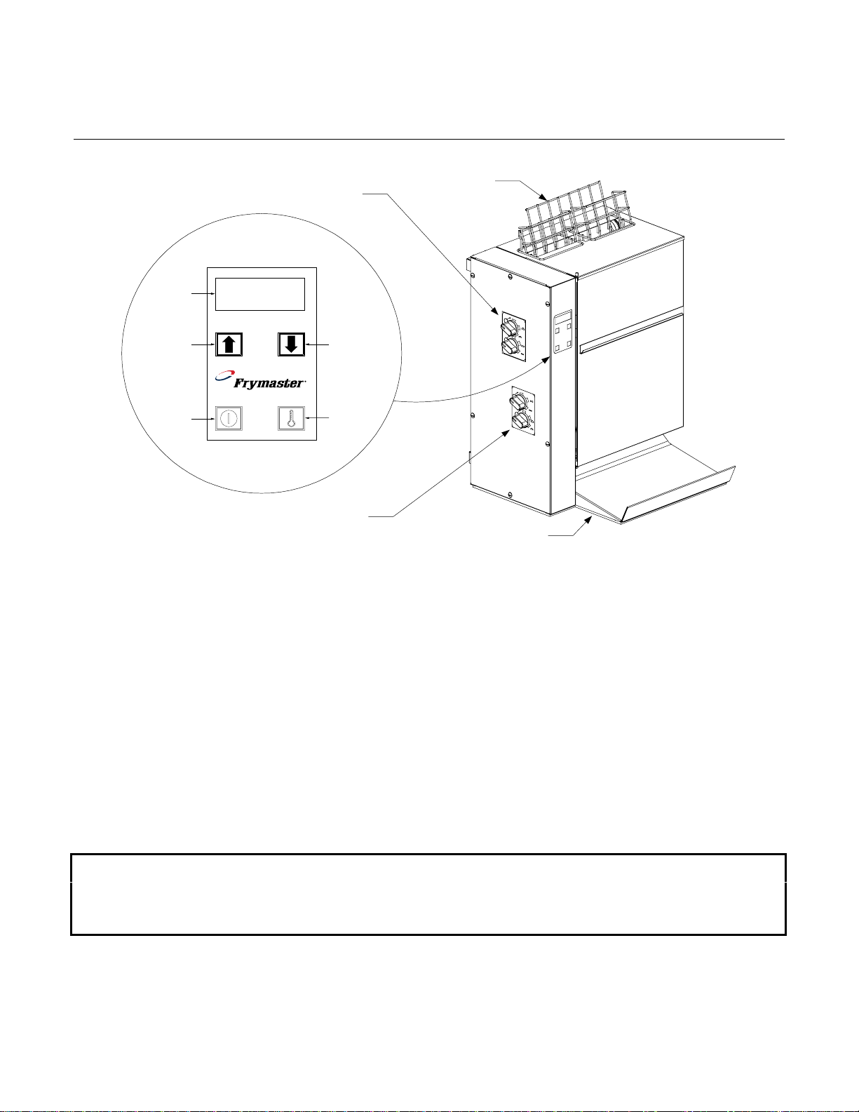
1.1 CT16 Toaster Functional Description
Bun Guide for Heel
and Crown Slots
Heated Holding Tray
The CT16 Toaster is designed to produce fresh, uniformly toasted buns on an "as needed” basis. The
countertop-mounted unit consists of a cabinet, a computer, a heating element and a pair of conveyor
assemblies.
When the unit is turned on, an electrical heating element (called a platen) is energized. The platen
heats up to a programmed temperature referred to as the setpoint. At the same time, both conveyor
assemblies are activated. When a bun is placed into one of the slots at the top of the cabinet, the
conveyor belts gently carry it through the unit, with the cut face of the bun passing over the heated
platen. As the bun passes over the platen, it is toasted. At the end of the process, the bun is deposited
onto a holding tray. The computer allows the operator to adjust the setpoint to obtain desired toasting
characteristics. Compression adjustment knobs also allow the operator to adjust the compression of
heels and crowns as they pass through the toaster.
1.2 Power Requirements
ALL ELECTRICALLY OPERATED APPLIANCES MUST BE ELECTRICALLY GROUNDED IN ACCORDANCE WITH LOCAL CODES, OR
PLUGGED INTO A PROPERLY GROUNDED RECEPTACLE. DO NOT CUT OR REMOVE THE GROUNDING PRONG FROM THIS PLUG!
• Voltage: 200VAC, 208VAC, or 240VAC, depending on model ordered
• Frequency: 60 Hz (non-CE )or 50 Hz (CE and Australian models)
• Phase: Single
• Service: 20 Amp
IN THE ABSENCE OF LOCAL CODES, WITH THE NATIONAL ELECTRICAL CODE (ANSI/NFPA NO. 70-1990) OR THE
CORRESPONDING NATIONAL CODE OF THE COUNTRY IN WHICH INSTALLED.
THIS APPLIANCE IS EQUIPPED WITH A GROUNDING PLUG FOR YOUR PROTECTION AGAINST SHOCK HAZARD AND MUST BE
1-1
Page 4

1.3 Replacing Components
Accessing the Electronics
1. Pull the bun compression knobs off their shafts.
2. Remove the screws around the edge of the component housing cover and remove the cover.
Accessing the Drive Motor and Auxiliary Transformer
Carefully lay the unit on its back and remove the seven screws that secure the bottom cover in place.
Removing the Conveyor Assemblies
1. Turn off and unplug the unit.
2. Remove the bun feeder then remove the cover by lifting it straight up until it is clear of its hinge
pins.
3. Rotate the bun compression knobs to positions 5 and E.
4. Press down on the top roller(s) of the conveyor assembly to be removed to lock it (them) in the
down position.
5. Rotate the tray stabilizer latch upward, then remove the belt(s). Return the tray stabilizer latch to
the latched position.
6. Pull the bun compression knobs from their shafts.
7. Remove the screws around the edge of the component housing cover and remove the cover.
8. Remove the diagonal brace.
9. Release the tension on the drive belt by pressing down on the belt tensioner arm and remove the
belt from the pulleys.
10. To remove the dual-belt conveyor assembly:
(See illustration on following page.)
a. Loosen the setscrew in the forward-most drive pulley and remove the pulley.
b. Remove the cartridge heater, marking the leads to facilitate reconnection.
c. Remove the four hex-head screws and two flange nuts that secure the conveyor assembly to the
component housing from the inside.
d. Rotate the tray stabilizer latch upward and, while supporting the conveyor assembly, remove the
two hex-head screws securing the top of the conveyor assembly from the outside (conveyor
side) of the component housing and carefully pull the conveyor assembly away from the housing.
e. Reinstall the conveyor assembly by reversing the steps performed, being sure to reattach the
ground wire with the top hex head screw.
1-2
Page 5
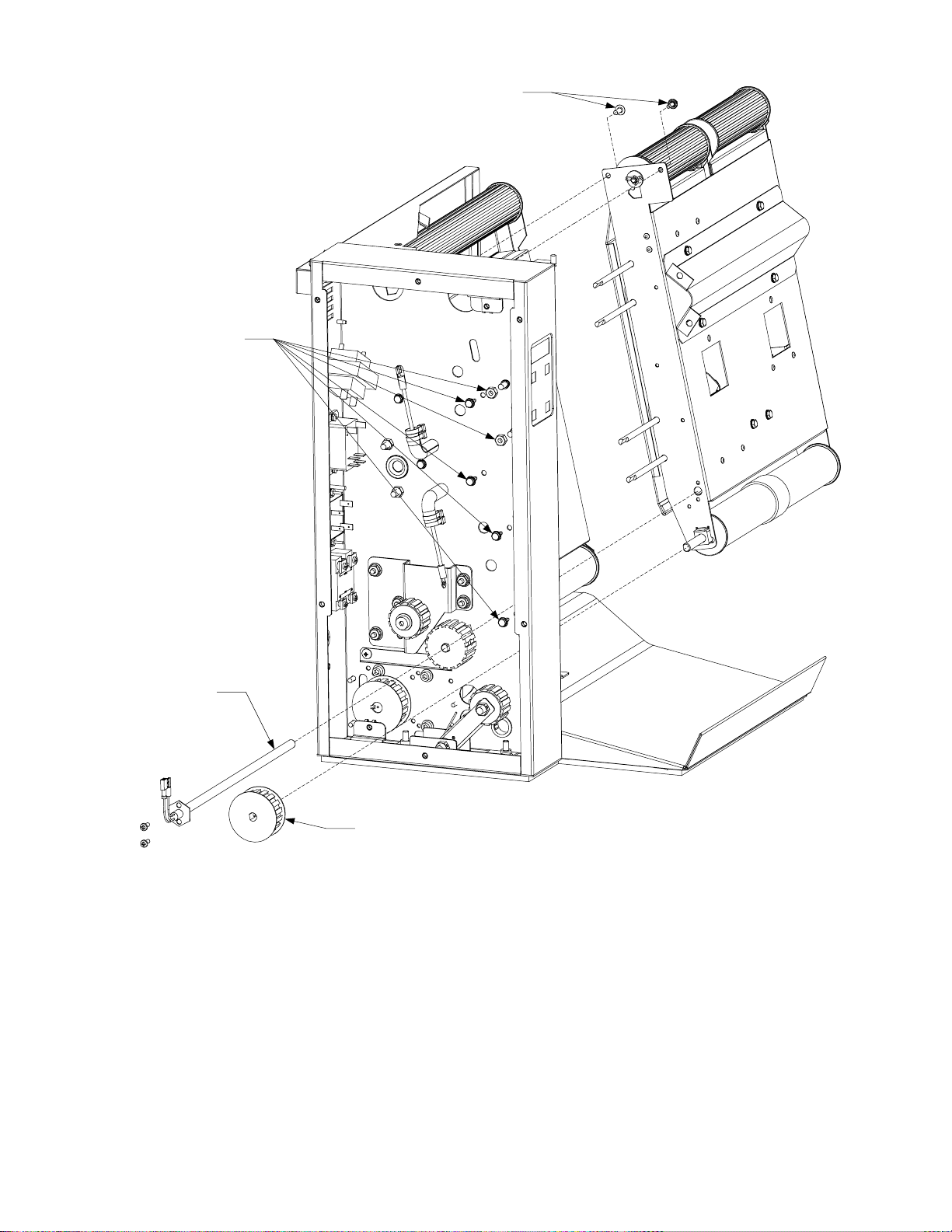
Step 10c - Remove
these four hex head
screws and two nuts.
Step 10d - Remove last two screws
and pull conveyor away from housing.
Step 10b - Remove
cartridge heater.
Step 10a - Remove drive pulley.
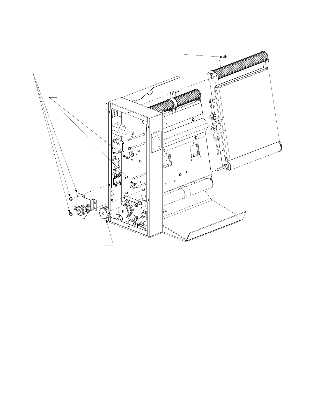
11. To remove the toasting conveyor assembly:
(See illustration on following page.)
a. Detach the platen and probe wiring from the relay, high-limit, and 9-pin connector.
b. Loosen the setscrew in the second drive pulley from the front and remove the pulley.
c. Remove the five flange nuts that secure the idler assembly to the housing and remove the idler
assembly.
d. Remove the two hex head screws shown in Step 11d of the illustration on the following page.
1-3
Page 6
e. Rotate the tray stabilizer latch upward and, while supporting the conveyor assembly, remove the
hex-head screw securing the top of the assembly from the outside (conveyor side) of the
component housing and carefully pull the assembly away from the housing.
Step 11e - Remove the last screw and pull
the conveyor away from the housing.
Step 11c - Remove
these five flange nuts
and the idler assembly.
Step 11d - Remove these
two hex head screws.
Step 11b - Remove the drive pulley.
f. Reinstall the conveyor assembly by reversing the steps performed, being sure to reattach the
two ground wires with the lower of the two hex head screws removed in Step 11d.
Replacing the High-Limit Thermostat or Heater Probe
(See illustration on following page.)
1. Turn off and unplug the unit, and remove toasting conveyor in accordance with the instructions on
Pages 18-19.
2. To replace the high-limit thermostat, remove the platen tray brace to expose the thermostat and
remove the screws securing it in place.
3. To replace the heater probe, remove the plug over the probe to expose the component. Remove
the screw securing the probe retainer and remove the probe.
1-4
Page 7
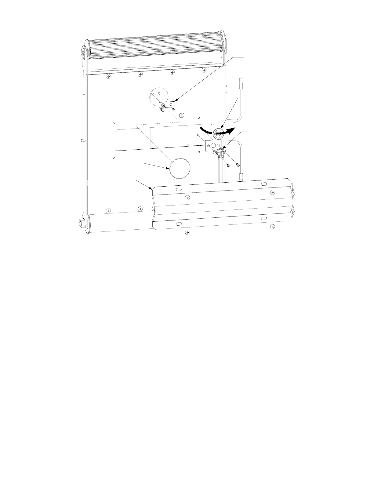
Platen Tray Brace
Heater Probe
NOTE: Probe
and high limit
wires must be
routed through
this bushing as
shown by large
arrow.
High Limit
Plug
4. Replace the failed component, being sure to route the component wires through the bushing as
shown in the illustration above. Reassemble by reversing the steps performed and reconnect the
wiring in accordance with the wiring diagram on the inside of the component housing cover.
Replacing the Drive Motor or Auxiliary Transformer
(See illustration on following page.)
1. Turn off and unplug the unit.
2. Pull the bun compression knobs from their shafts.
3. Remove the screws around the edge of the component housing cover.
4. Disconnect the failed component’s wiring, then carefully lay the unit on its back.
5. Remove the screws that secure the bottom cover in place and remove the cover. NOTE: The two
cap screws that pass through the bottom of the component housing also hold the belt tensioner
assembly in place.
6. To replace the drive motor, remove the screws that secure the diagonal brace to the component
housing. Remove the drive belt. Loosen the setscrew securing the motor pulley to the motor shaft
and remove the pulley. Hold the replacement motor next to the failed motor and transfer the wiring
connections to the replacement. Remove the four screws that secure the motor to the cabinet and
install the replacement.
1-5
Page 8
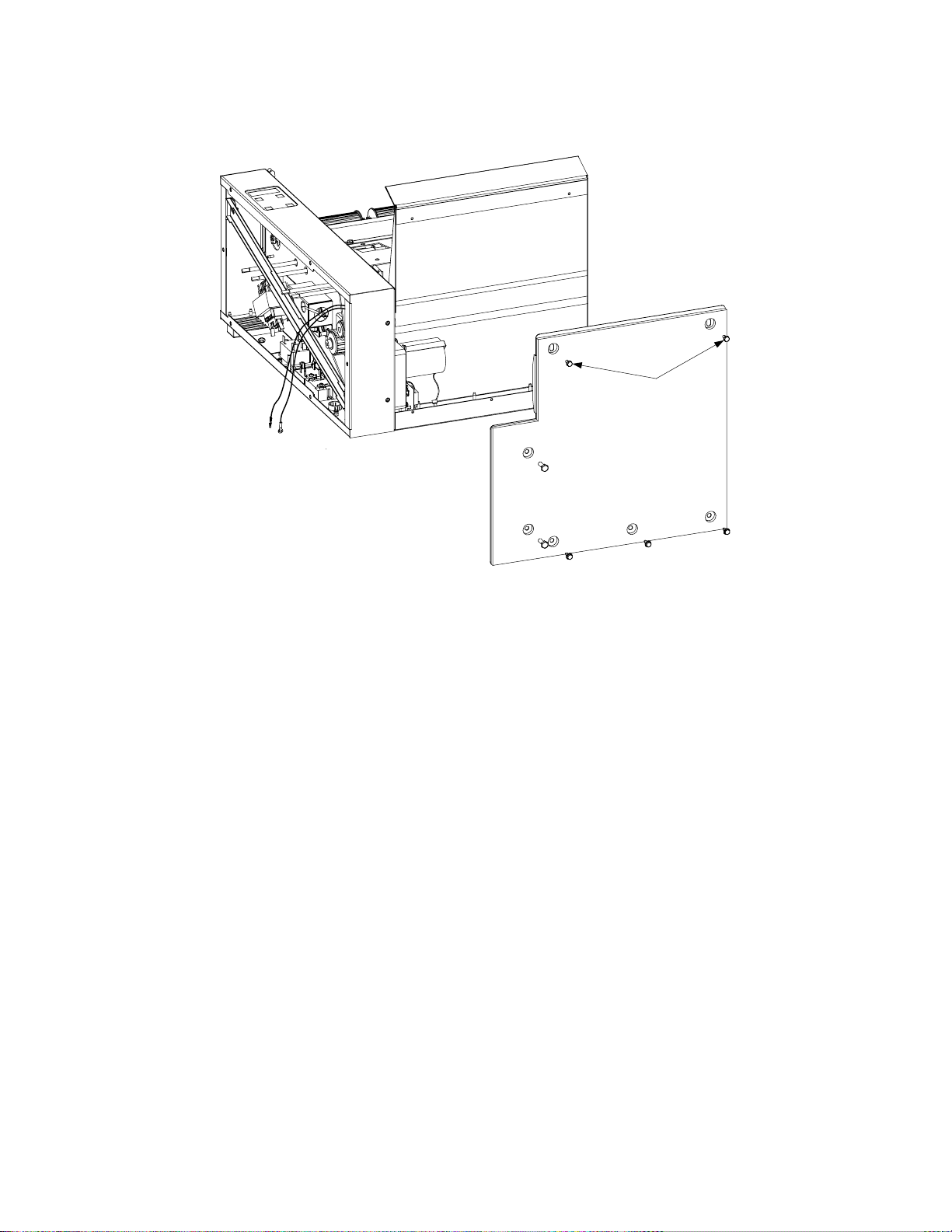
7. To replace the auxiliary transformer (present only in 200V and 208V units), hold the replacement
next to the failed transformer and, one at a time, disconnect the wires from the failed transformer
and connect them to the replacement. When all wiring has been transferred, remove the screws
and nuts that secure the transformer to the back wall of the motor compartment and install the
replacement.
Short screws
8. Reverse the steps performed to reassemble unit.
Replacing the Dual Belt Conveyor Cartridge Heater
1. Turn off and unplug the unit.
2. Pull the bun compression knobs off their shafts.
3. Remove the screws in the edge of the component housing cover.
4. Disconnect the heater leads. Remove the hex-head screws securing the heater in place and
remove the heater (see illustration on Page 1-6).
5. Reverse steps 1-4 to reassemble the unit.
Replacing the Transformer or Relays
1. Turn off and unplug the unit.
2. Pull the bun compression knobs from their shafts.
3. Remove the screws in the edge of the component housing cover.
4. Hold the replacement component next to the component to be replaced and, one at a time,
disconnect the wires from the failed component and connect them to the replacement component.
5. Remove the screws and/or nuts securing the failed component to the component housing and
install the replacement.
6. Reverse steps 1-3 to reassemble the unit.
1-6
Page 9

1.4 Technician Troubleshooting
PROBLEM PROBABLE CAUSES CORRECTIVE ACTION
A. Failed transformer.
Display remains blank
when unit turned on.
B. Failed computer.
C. Failed cover interlock switch or failed
high limit.
A. Failed motor. A. If platen is heating, replace motor.
Computer display is on, but
motor is not running
Motor is running at wrong
speed (i.e. average time for
three individual buns to
pass through toaster is
NOT between 15 and 18
seconds).
B. Broken/loose wire between computer and
latch relay or failed latch relay.
A. Toaster improperly configured for power
supply.
A. Improper power-supply.
B. Failed temperature probe.
Platen heats, but unit does
not reach setpoint.
C. Failed computer.
A. Check for line voltage on the primary
(line) side of transformer and 12VAC on
secondary (load) side of transformer. If
line voltage is present but secondary
voltage is not 12VAC, the transformer has
failed.
B. Check continuity between right terminal
of secondary (load) side of transformer
and Pin 9 of the 9-pin connector when the
cover interlock switch is closed. If
resistance is zero, replace the computer.
C. Check continuity between switch
terminals when the switch is closed.
If resistance is infinite, replace switch. If
resistance is zero, replace high limit.
B. Check for 12VDC on Pins 6 & 7 of
computer. If present and wiring is intact,
replace latch relay. If not present, replace
computer.
A. Check data plate for voltage rating, and
verify that power supply and toaster
match.
A. Verify that the power supply is 20 amp
single-phase 200, 208 or 240VAC
(depending upon model).
B. Use a temperature-measuring device to
determine actual platen temperature. If
measured temperature is within 10 degrees
of the temperature displayed on the
computer and the probe resistance at pins
3 and 5 of the 9-pin connector does not
correspond to the appropriate value in the
probe resistance chart on Pages 24 and 25,
replace the probe.
C. Use a temperature-measuring device to
determine actual platen temperature. If
measured temperature is within 10 degrees
of the temperature displayed on the
computer and probe resistance at pins 3
and 5 of the 9-pin connector corresponds
to the value in the probe resistance chart
on Pages 24 and 25, replace the computer.
1-7
Page 10

PROBLEM PROBABLE CAUSES CORRECTIVE ACTION
A. Check for 12VDC on computer pins 6 &
7. If NOT present AND motor is running,
replace computer. Check for 5VDC on
A. Failed computer.
terminals 3 & 4 of main heater relay and
pins 1 and 6 of computer. If NOT present
at either point AND motor is running,
replace computer.
B. Broken/loose wire between computer and
latch relay, or failed latch relay.
B. Check for 12VDC on computer pins 6 &
7. If present and wiring is intact, replace
latch relay.
C. Determine temperature of platen then
measure main heater probe resistance at
Platen does not heat, but
computer display is on.
C. Failed main heater probe.
pins 3 & 5 of 9-pin connector. If the
probe resistance is NOT approximately
equal to the corresponding resistance in
the chart on Pages 24 and 25, replace the
probe.
D. Check for 5VDC on terminals 3 & 4 of
D. Broken/loose wire between computer and
main heater relay, or failed main heater
relay.
main heater relay AND on computer pins
1 & 6. If present on pins 1 & 6, but NOT
on terminals 3 & 4, and wiring is intact,
replace the main heater relay.
E. Check for 5VDC on terminals 3 & 4 of
main heater relay and for line voltage on
E. Failed platen.
terminal 2 of main heater relay and
terminal 4 of latch relay. If expected
voltage is present at all three points,
replace the platen.
Probe Resistance Chart
For use with CT16 Series toasters manufactured with Minco Thermistor probes only.
FOHMSC FOHMSC FOHMSC FOHMSC FOHMSC
60 1059 16 160 1268 71 260 1473 127 360 1674 182 460 1872 238
65 1070 18 165 1278 74 265 1483 129 365 1684 185 465 1882 241
70 1080 21 170 1289 77 270 1493 132 370 1694 188 470 1892 243
75 1091 24 175 1299 79 275 1503 135 375 1704 191 475 1901 246
80 1101 27 180 1309 82 280 1514 138 380 1714 193 480 1911 249
85 1112 29 185 1320 85 285 1524 141 385 1724 196 485 1921 252
90 1122 32 190 1330 88 290 1534 143 390 1734 199 490 1931 254
95 1133 35 195 1340 91 295 1544 146 395 1744 202 495 1940 257
100 1143 38 200 1350 93 300 1554 149 400 1754 204 500 1950 260
105 1154 41 205 1361 96 305 1564 152 405 1764 207 505 1960 263
110 1164 43 210 1371 99 310 1574 154 410 1774 210 510 1969 266
115 1174 46 215 1381 102 315 1584 157 415 1783 213 515 1979 268
120 1185 49 220 1391 104 320 1594 160 420 1793 216 520 1989 271
125 1195 52 225 1402 107 325 1604 163 425 1803 218 525 1998 274
130 1204 54 230 1412 110 330 1614 166 430 1813 221 530 2008 277
135 1216 57 235 1422 113 335 1624 168 435 1823 224 535 2018 279
140 1226 60 240 1432 116 340 1634 171 440 1833 227 540 2029 282
145 1237 63 245 1442 118 345 1644 174 445 1843 229 545 2039 286
150 1247 66 250 1453 121 350 1654 177 450 1852 232 550 2049 288
155 1258 68 255 1463 124 355 1664 179 455 1862 235
1-8
Page 11

1.5 Wiring Diagrams
NOTE: These diagrams depict wiring as of the date of manual publication. They may not
reflect design changes made to the equipment after publication. Always refer to the wiring
diagram affixed to the unit when actually troubleshooting or servicing this equipment.
NON-CE TOASTERS
1-9
Page 12

CE AND AUSTRALIAN TOASTERS
1-10
Page 13

1.6 Schematic
LINE VOLTAGE
LINE FILTER (CE AND AUSTRALIAN TOASTERS ONLY)
Transformer
COM NO
12Volt
Secondary
Cover
Interloc
k
High
Limit
98
3
6
COMPUTER
5
Main
Heater
Probe
4
Resistor
12
Latch
Relay
6
8
3
4
2
Main
Heater
Relay
Main
Heater
7
1
0
2
4
1
Cartridge
Heater
Drive Motor
M
Fan
F
1-11
Page 14

THIS PAGE INTENTIONALLY LEFT BLANK.
Page 15

CT16 SERIES TOASTER
SERVICE AND PARTS MANUAL
CHAPTER 2: PARTS LIST
2.1 Introduction
CT16 Toasters manufactured for use in the European Union (CE) and those manufactured for use
elsewhere are identical in most respects, but there are some important differences. The paragraphs
that follow summarize the differences and provide a list of the parts that are unique to each model.
The most significant differences are in the electronic components. Units built for the CE and Australian
markets have a 50 Hz motor; all others have a 60 Hz motor. Non-CE and CE/Australian units also use
different transformers, and CE/Australian units have a line filter built into the electrical power supply
system. The line filter and cover are attached to the rear of the cabinet.
Because of the difference in the power cycle frequency (50 Hz vs. 60 Hz), CE and Australian units are
equipped with 10-tooth drive pulleys and a 28-Tooth motor pulley. Standard units have 17-tooth drive
pulleys and an 18-tooth motor pulley. The different pulleys on the CE and Australian units maintain the
correct belt speed even though the RPM of the motor at 50 Hz is slightly slower than that of the motor
at 60 Hz.
The table below identifies the components that are unique to each configuration.
Components Unique to CE andAustralian Units Components Unique to Non-CE Units
P/N Description P/N Description
807-2191 Transformer (208-240V/12V) 807-0979 Transformer (208-240V/12V)
807-0910 Transformer Fuse, 250V/3A N/A Not used.
106-0781 Transformer and Bracket Assembly N/A Not used.
807-3472 Line Filter N/A Not used.
824-0896 Line Filter Cover N/A Not used.
106-2143 Tensioner Assembly, Drive Belt 106-2723 Tensioner Assembly, Drive Belt
810-2300 28-Tooth Motor Driven Pulley 810-2565 18-Tooth Motor Driven Pulley
810-2301 10-Tooth Dual Belt Drive Pulley 810-2566 17-Tooth Dual Belt Drive Pulley
810-2332 10-Tooth Toasting Belt Drive Pulley 810-2564 17-Tooth Toasting Belt Drive Pulley
The illustrations in the parts list that follows also identify the CE/Australian and Non-CE components.
2-1
Page 16

2.2 Cabinetry
16
17
18
1
27
13
11
27
12
28
29
8
9
10
2423
30
6
29
7
29
19 20
21
14
16
22 26
2
3
4
30
25
5
2-2
Page 17

ITEM PART # COMPONENT
1 106-2720SP Back Cover Assembly
2 824-1117 Tray Assembly, Toast
3 816-0573 Insulation, Toast Tray
4 200-4270 Bottom, Toaster
5 816-0589 Seal, Toaster Base
6 823-3988 Housing, Component
7 210-5311 Bracket, Lower Hinge
8 823-2941 Bracket, Upper Hinge
9 210-3434 Cover, Air Inlet
10 200-2877 Brace, Component Housing
11 210-2876 Cover, Component Housing
12 810-2331 Knob, Compression Adjustment
13 106-0785SP Cover, Line Filter (used on CE and Australian units only)
14 810-2549 Guide, Bread (Wireform Feeder)
15 106-2158 Cover Assembly, Toaster (includes Items 16-21)
16 823-3656 Cover (does not include Items 17-21)
17 810-0066 Magnet
18 810-1683 Handle, Cover
19 910-9458 Reinforcement, Cover Side
20 809-0184 Washer, #10 Lock
21 809-0107 Screw, 8-32 x ⅜-inch Slotted Round Head
22 809-0104 Screw, 8-32 x ½-inch Slotted Truss Head
23 809-0112 Screw, 8-32 x 1 ¼-inch Slotted Truss Head
24 809-0247 Nut, 8-32 Hex
25 809-0434 Screw, #10 x ⅜-inch Hex Washer Head
26 809-0448 Clip, Tinnerman
27 826-1330 Screw, 10-32 x ⅜-inch Slotted Truss Head (Pkg. of 25)
28 826-1374 Screw, #10 x ½-inch Hex Head (Pkg. of 25)
29 826-1379 Screw, #10 x ½-inch Philips Truss Head (Pkg. of 10)
30 826-1389 Screw, ¼-20 x ¾-inch Hex Head (Pkg. of 10)
* 810-1712 Clip, Adhesive-backed Wire Routing
* Not illustrated
2-3
Page 18

2.3 Conveyor Assembly, Dual Belt
3
19
24
12
21
17
18
5
22
18
15
8
1
9
7
10
5
23
11
20
4
17
16
7
13
2
6
14
2-4
Page 19

ITEM PART # COMPONENT
1 806-9200 Roller Assembly, Dual Belt Idler
2 806-9318 Roller Assembly, Dual Belt Drive
3 810-2303 Washer, Teflon Crumb
4 809-0132 Screw, ¼-20 x ¾-inch Slotted Pan Head
5 826-1374 Screw, #10 x ½-inch Hex Head (Pkg. of 25)
6 809-0647 E-Ring
7 809-0745 Washer, ¼-inch Flat
8 810-1672 Spring, Compression Plate
9 810-1718 Shaft, Short Dual Belt Roller
10 810-1776 Pin, VT Cotter
11 810-1802 Bushing, Tray Stabilizer Latch Support
12 810-1818 Spring, 3.00-inch Long, 4.6 Lbs./Inch
13 810-2305 Bushing
14 816-0389 Belt, Dual Conveyor
15 823-2719 Plate Assembly, VT Right Pressure
16 823-3578 Plate Assembly, VT Left Pressure
17 823-2722 Cam Assembly, VT Long
18 823-2723 Cam Assembly, VT Short
19 823-2798 Cover Assembly, VT Spring
20 823-2838 Latch Assembly, VT Tray
21 823-3989 Tray Assembly, Dual Belt
22 900-8155 Bracket, Guide Rod
23 910-8254 Brace, Dual Belt Tray
24 910-8512 Bracket, Spring Guide Receiver
25 210-4245 Bracket, Left Center Support
26 210-4246 Bracket, Right Center Support
2-5
Page 20

2.4 Conveyor Assembly, Toasting
6
28
3
11
1013
27
24
14
1
18
19
22
12
20
7
5
28 29 30
31
25
2
15
8
17
4
16
2-6
Page 21

ITEM PART # COMPONENT
1 106-2123SP Tray with Grommet, VT Platen
2 210-0318 Crumb Shield, Toasting Conveyor
3 806-9195 Roller, VT Toasting Belt Idler
4 806-9196SP Platen Assembly, VT
5 806-9199 Roller, VT Toasting Belt Drive
6 810-2303 Washer, Teflon Crumb
7 809-0266 Screw, #10 x ½-inch Philips Truss Head
8 809-0647 E-Ring
9 809-0650 Screw, 10-32 x ⅜-inch Button Socket Head
10 809-0745 Washer, ¼-inch Flat
11 810-1721 Shaft, Long Roller
12 810-1736 Plug, 1.75-inch Stainless Button
13 810-1776 Pin, VT Cotter
14 810-1818 Spring, 3-inches Long, 4.6 Lbs./Inch
15 810-2305 Bushing, Roller
16 816-0379 Belt, Toasting
17 816-0403 Insulation, Platen
18 823-2726 Slide Assembly, Belt Tension
19 910-8246 Guide, Crumb Shield
20 910-8254 Brace, VT Platen Tray
*21* 910-8512 Bracket, Slide Assembly Receiver
22 810-1722 Grommet, .5-inch I.D. x 1.05-inch O.D. (Integral component of Item 1)
23 810-2013 Roller, VT Drive (Integral component of Item 3)
24 810-1810 Bushing, Teflon (Integral component of Item 3)
25 807-3037 Thermostat, High-Limit (Integral component of Item 4)
26 910-8637 Spacer, High-Limit Thermostat (Integral component of Item 4)
27 809-0729 Capscrew, 6-32 x ¼-inch Socket Head (Integral component of Item 4)
28 807-3247 Probe, Heater (Integral component of Item 4)
29 910-8757 Retainer, Heater Probe (Integral component of Item 4)
30 826-1330 Screw, 10-32 x ⅜-inch Slotted Truss Head (Integral component of Item 4)
31 810-1658 Platen, 5000W (Integral component of Item 4)
* Obscured by Item 1. See Item 24 on Page 5 for illustration.
2-7
Page 22

2.5 Electronic Components
15
14
7
6
5
4
3
2
1
8
10
13
9
12
2-8
11
Page 23

ITEM PART # COMPONENT
1 807-3213 Relay, Solid State 5A 3/16 Control Terminals
2 807-3021 Relay, 30A 12VDC DPST NO
3 826-1562 Relay, Solid State 40A 280V SPST NO
4 106-0781SP Transformer and Bracket Assembly, CE and Australian
* 807-0910 Fuse, 250V 3A (fuse for CE/Australian transformer)
5 807-0979 Transformer, 208-240VAC/12VAC, 50/60 Hz, 43VA, Non-CE
7 806-9296 Computer Assembly, VT
8 807-3196 Heater, 240V 165W Cartridge
9 807-3064 Switch, Cover Interlock
10 806-9796 Resistor Assembly, Holding Tray
11 807-3243 Cordset, Standard Twist-Lock
12 807-3198 Cordset, Hooded Twist-Lock
13 807-3242 Cordset, Pin and Sleeve
14 807-3529 Cordset, CE VT
15 807-3850 Cordset, Australian VT
*Not illustrated.
2-9
Page 24

2.6 Motor, Drive Train, and Fan Components
See Page 6
3
4
See Page 4
8
7
2
9
1
5
ITEM PART # COMPONENT
1 Motor Assembly, 50/60 Hz
106-3052 200-208V VT Drive
106-2841 220-250V VT Drive
2 810-2302 Drive Belt
3 106-2128 Bracket Assembly, VT Idler Pulley
4 826-1368 Nut, ¼-20 Serrated Flange (Pkg. of 10)
5 Pulley, Motor Driven
810-2565 18-Tooth (Non-CE
810-2704 21-Tooth (CE and Australian)
6 106-2723 Tensioner Assembly, Drive Belt
7 810-2566 Pulley, 17-Tooth Dual Belt Drive
8 810-2564 Pulley, 17-Tooth Toasting Belt Drive
9 106-2703 Fan Assembly, VT Motor Cooling
6
2-10
Page 25

THIS PAGE INTENTIONALLY LEFT BLANK.
Page 26

Frymaster, L.L.C., 8700 Line Avenue, PO Box 51000, Shreveport, Louisiana 71135-1000
Shipping Address: 8700 Line Avenue, Shreveport, Louisiana 71106
TEL 1-318-865-1711 FAX (Parts) 1-318-688-2200 FAX (Tech Support) 1-318-219-7135
PRINTED IN THE UNITED STATES
SERVICE HOTLINE
1-800-551-8633
819-5993
JANUARY 2004
 Loading...