

Page 1
Sierra User Manual
Sierra ROU10W
Multi-Operator/Multi-Band DAS
User Manual
VER 1.0
© FRTek Co. Ltd 2015 1
Confidential: Any reproduction or distribution without the express
written consent of FRTek is strictly prohibited
P/N: FR-RMDL10U @ revision 1.0
Page 2

Sierra ROU 10W User Manual
Table of Contents
1. Overview………………………………………………………………………………………………...7
1.1 Product Overview………………………………………………………………….……..7
1.2 System Features…………………………………………………………………………...7
2. System Network Configuration………………………………………………………………..9
3. System Architecture…………………………………………………………………………………13
3.1 Architecture………………………………………………………………………………….13
4. System Specifications……………………………………………………………………………….23
4.1 System Specification
4.2 Environmental conditions
5. Operational Program
5.1 Overview
5.2 Screen configuration
5.3 ROUStatus Verification and Control
5.4 Reset
5.5 Set-up Time Advance
5.6 Download
5.7 Debug
6. Main Technical Details
6.1 Main Technical details
6.2 Technical Details
7. Alarm and Troubleshooting
© FRTek Co. Ltd 2015 2
Confidential: Any reproduction or distribution without the express written consent of FRTek Co. Ltd
or FRTek US LLC is strictly prohibited
Page 3
Sierra ROU 10W User Manual
This equipment generates or uses radio frequency energy. Changes or modifications to this equipment
may cause harmful interference unless the modifications are expressly approved in the instruction
manual. The user could lose the authority to operate this equipment if an unauthorized change or
modification is made.
The head end unit must always be connected to the Base Station using a direct cabled connection.
This system has not been approved for use with a wireless connection via server antenna to the base
station.
Antennas must be installed in accordance with FCC 27.50. With 17dBi gain antennas the height of the
antenna above average terrain (HAAT) must not exceed 915m. For difference gain antennas refer to the
relevant rules.
FCC WARNING
INFORMATION TO THE USER
Part 27.5
Booster Warning Label
WARNING. This is NOT a CONSUMER device. It is designed for installation by FCC
LICENSEES and QUALIFIED INSTALLERS. You MUST have an FCC LICENSE or
express consent of an FCC Licensee to operate this device. Unauthorized use may result
in significant forfeiture penalties, including penalties in excess of $100,000 for each
continuing violation.
Specification or recommendation about Antennas is not available or not mention in this manual.
As per default antennas, cables or coupling devices, contact www.frtek.net for further information.
© FRTek Co. Ltd 2015 3
Confidential: Any reproduction or distribution without the express written consent of FRTek Co. Ltd
or FRTek US LLC is strictly prohibited
Page 4
Sierra ROU 10W User Manual
1. Overview
1.1 SIERRA Overview
This manual is created for operators who is using or will use Sierra DAS system to give an information and an
instructions how to figure out the system.
Operator shall be acknowledged, experienced and properly educated about the overalls of repeater system
and the experience of the installation & maintenance of DAS system.
1.2 Use of recommendation and warning
Booster Warning Label
WARNING. This is NOT a CONSUMER device. It is designed for installation by FCC
LICENSEES and QUALIFIED INSTALLERS. You MUST have an FCC LICENSE or
express consent of an FCC Licensee to operate this device. Unauthorized use may result
in significant forfeiture penalties, including penalties in excess of $100,000 for each
continuing violation.
Warning
Use of unauthorized antennas, cables, and/or coupling devices not conforming with ERP/EIRP and/or
indoor-only restrictions is prohibited.
Caution
This symbol indicates cautions which operators shall be careful while installing and managing systems
1.3 System Features
Sierra is an in-building/outdoor DAS system and provides 4 bands of service; 700MHz (LTE, 27MHz), 850MHz
(WCDMA, LTE 32MHz), 1.9GHz (WCDMA, LTE 65MHz), 2.1GHz (WCDMA, LTE, 45MHz) at the same time. The system
is scalable to extend additional 2 bands services - 2.3GHz and 2.5GHz frequencies. Sierra system is configured and
features:
A. ROU : Remote Optic Unit
- Type
1. ROU 10W : 700MHz SISO, 700MHz MIMO, 850MHz SISO, 1.9GHz SISO, 2.1GHz SISO, 2.1GHz MIMO
© FRTek Co. Ltd 2015 4
Confidential: Any reproduction or distribution without the express written consent of FRTek Co. Ltd
or FRTek US LLC is strictly prohibited
Page 5
Sierra ROU 10W User Manual
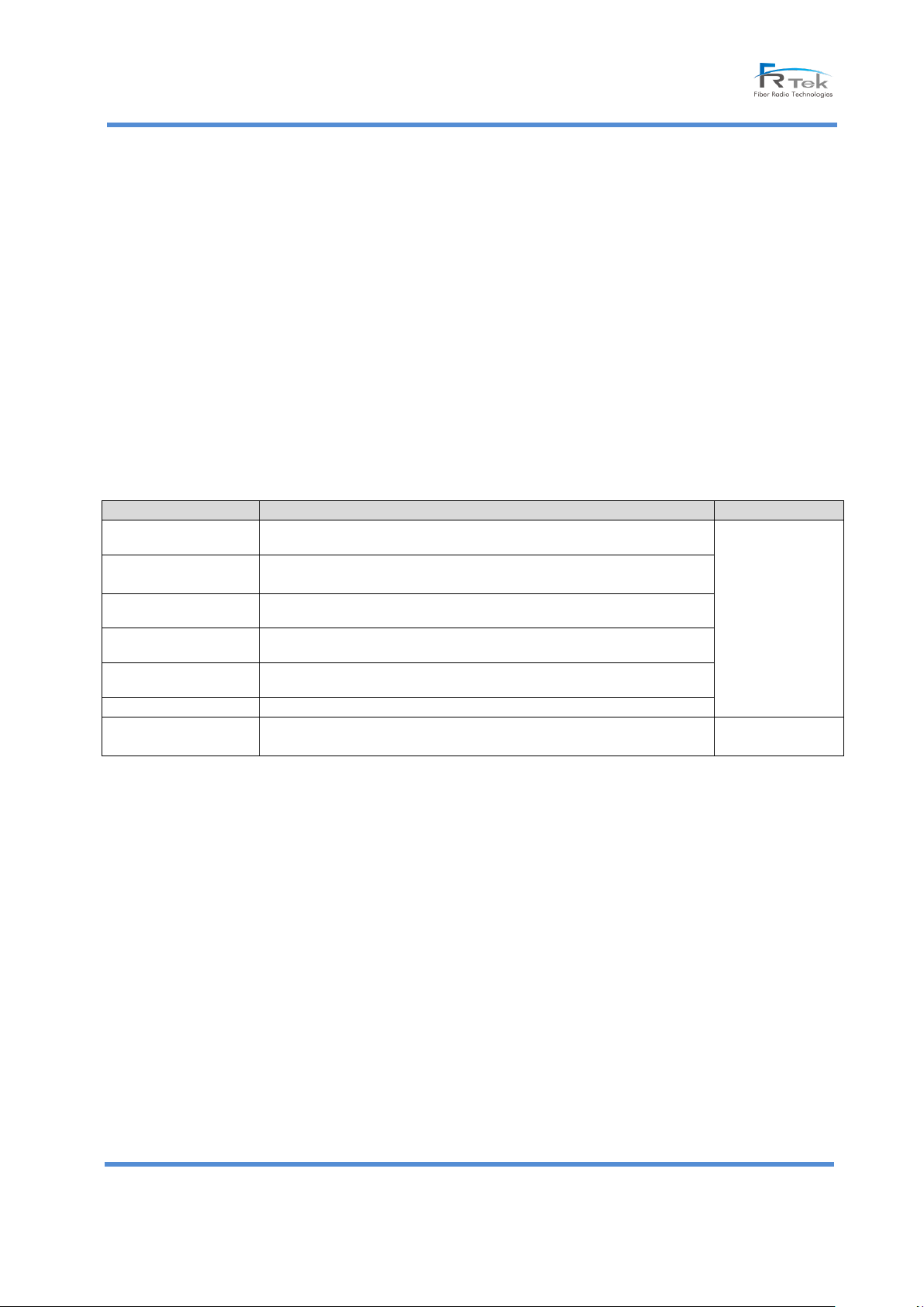
Port Type
Description
Port Location
Input Power
Single AC Power Input
Bottom side
Antenna
6 ports (700MHz SISO, 700MHz MIMO, 850MHz SISO, 1.9GHz SISO,
2.1GHz SISO, 2.1GHz MIMO)
Optic Cable
Optic Cable inputs – 3 ports (TR, IR, EX)
BATTERY
Pb BATT, Li-BATT inputs – 2 ports
External Fan
External Fan Power Input – Single port
Power Ground
Single port
Telecom Ground
2 ports
1 for each
Left/Right side
2. SROU 10W : 2.3GHz SISO, 2.3GHz MIMO, 2.5GHz SISO, 2.5GHz MIMO(Future ordering option)
- Conversion and amplification of digital optical signal into an RF signal (Downlink)
- Converting the RF signal into a digital optical signal (Uplink)
- Optic interfaces with MHU
- Node Isolation : Bypass to avoid impact on service of lower nodes in case of failure of upper nodes or
power off condition
- System Delay Equalizer (110us)
1.4 System Port Configuration
- Unauthorized cables and devices would give damages to the system.
Approved devices and cables are recommended to use.
A. ROU 10W Port Configuration
© FRTek Co. Ltd 2015 5
Confidential: Any reproduction or distribution without the express written consent of FRTek Co. Ltd
or FRTek US LLC is strictly prohibited
Page 6
Sierra ROU 10W User Manual
2. System Network Configuration
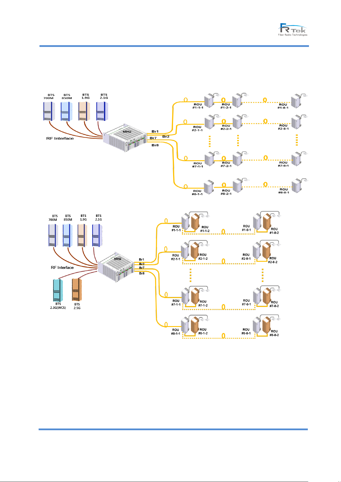
- The Sierra basic network configuration:
- Network configuration with SROU 10W expansion:
- MHU is interfacing with BTS(Base Transceiver Station) via RF cable and it has 8 optical interfaces with ROUs via
optical cable.
- ROU is interfacing with MHU using optic cable and can be cascaded with up to 8 ROUs.
- As for the scalability of Sierra, the total number of ROUs per each BR port is limited up to max. 8.
- SROU 10W is interfacing with ROU 10W through an optic cable and is installed in the same site of ROU.
© FRTek Co. Ltd 2015 6
Confidential: Any reproduction or distribution without the express written consent of FRTek Co. Ltd
or FRTek US LLC is strictly prohibited
Page 7
Sierra ROU 10W User Manual
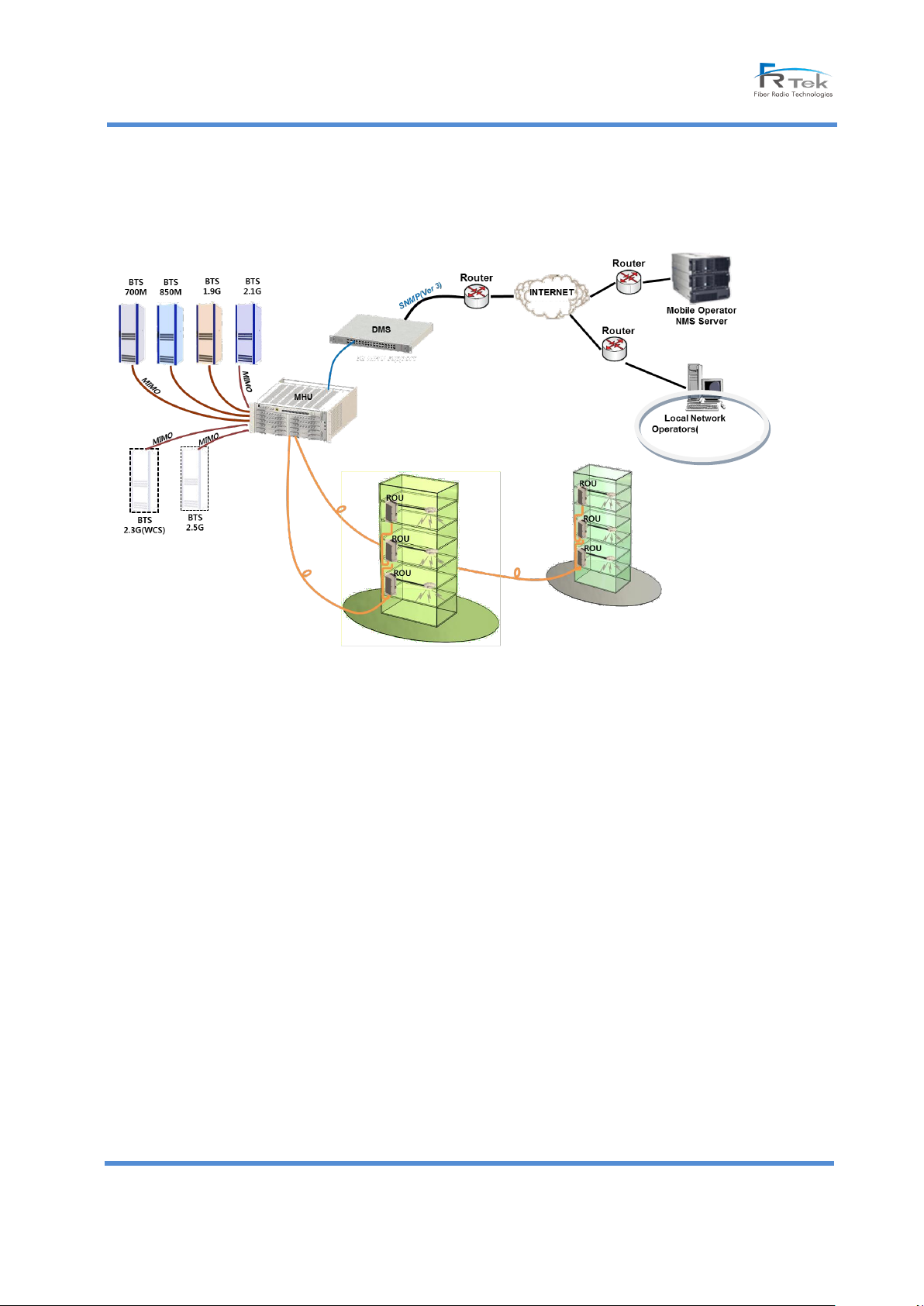
Offsite)
- MHU capacity can be scalable up to max. 64 ROUs plus 64 SROU 10Ws.
The network topology of Sierra is configured as follows;
© FRTek Co. Ltd 2015 7
Confidential: Any reproduction or distribution without the express written consent of FRTek Co. Ltd
or FRTek US LLC is strictly prohibited
Page 8
Sierra ROU 10W User Manual
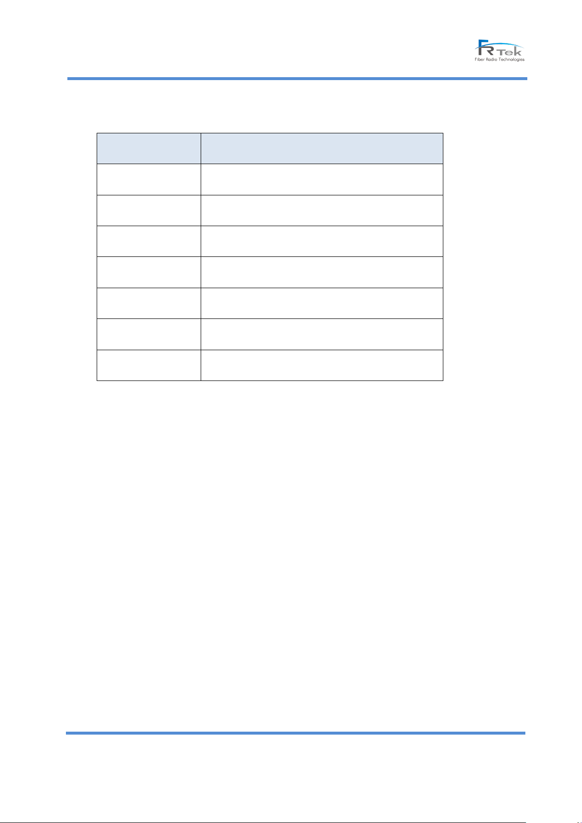
Function
ROU 10W
Input power
120V
Interface
(Input)
Optic
Interface
(Output)
RF
Service Band
Accommodation
LTE, Cellular, PCS, AWS, SMR, WCDMA
Type
10W : Indoor type
Cascading
Maximum 8
Back-up
Battery
Supported
Main features of Sierra
Advanced features of SIERRA
- Various network configurations (RF Interface with BTS. Various types of ROU configurations)
- Support for 700MHz(LTE,28MHz),850MHz(SMR, Cellular,25MHz),1.9GHz(PCS,65MHz), 2.1GHz(LTE,
45MHz) service/ In-building, etc.
- 4+2 bandwidth services on one ROU system
- Improving system efficiency by using the DPD, APD technology
- Node Isolation (ROU) to prevent service interruption from lower nodes
© FRTek Co. Ltd 2015 8
Confidential: Any reproduction or distribution without the express written consent of FRTek Co. Ltd
or FRTek US LLC is strictly prohibited
Page 9
Sierra ROU 10W User Manual
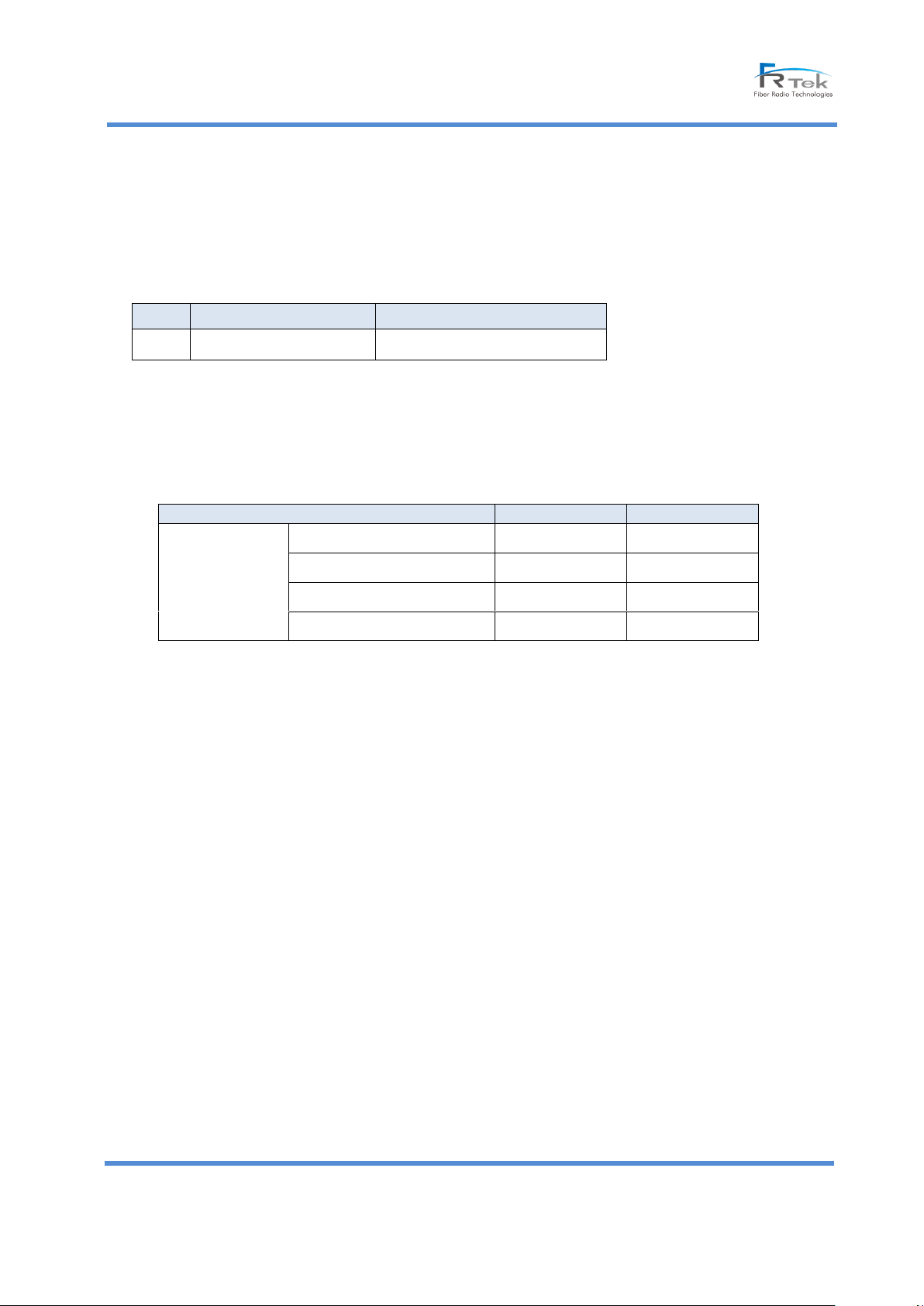
No.
Equipment
Part Numberl
1
ROU 10W
FR-RMDL10U
Service
SISO
MIMO
ROU 10W
700MHz
Applicable
Applicable
850MHz
Applicable
Not Applicable
1.9GHz
Applicable
Not Applicable
2.1GHz
Applicable
Applicable
3. System Architecture
3.1 Architecture
A. Types of Model
Sierra equipment is configured as shown below; the model name is as follows.
B. Design Considerations
- MHU and ROU use both an internal FAN and an external FAN to increase the cooling effect
- Definition of service
- Sierra provides a port connected to external battery in both ROU and MHU.
- RF Connector of MHU is a SMA female type and RF connector of ROU is a DIN-Type female type.
- The unit of this system is modular type in order for an easy module replacement and a maintenance
User is easy to plug-in or plug-out.
- Each units of this system are anti-insect , anti-dust and anti-pollution design structured.
- Each units of this system is designed to bear the vibration test regulation.
- Providing LTE Timing Advance function (0~110us).
© FRTek Co. Ltd 2015 9
Confidential: Any reproduction or distribution without the express written consent of FRTek Co. Ltd
or FRTek US LLC is strictly prohibited
Page 10
Sierra ROU 10W User Manual
Features
Item
Quantity
Interface spec
Remarks
Interface SPEC
AC 120V
1
MS Connector
Pb-BATTERY
1
MS Connector
Li-Battery
1
MS Connector
Antenna Port
6
DIN-Type Female
Optic Port
3
SMA Female
External FAN Port
1
MS Connector
Size
L*W*H (inch)
17.4"L x 15.35"W x 32.28"H
W/O rack mounting
brackets
With bracket
Weight
pound
170lb
10W
PWR Consumption
Watt
700
In lab test
condition
B. Structure and Shape per each equipment
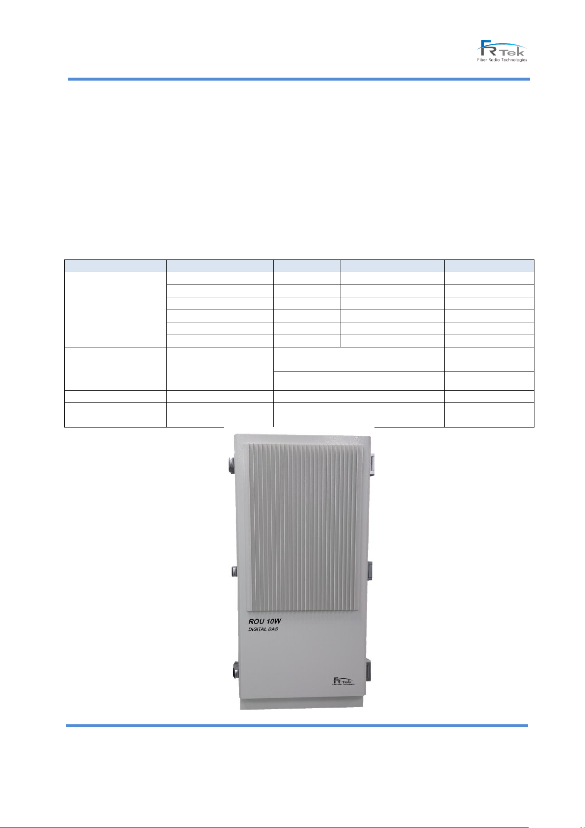
(1) ROU 10W Structure and Shape
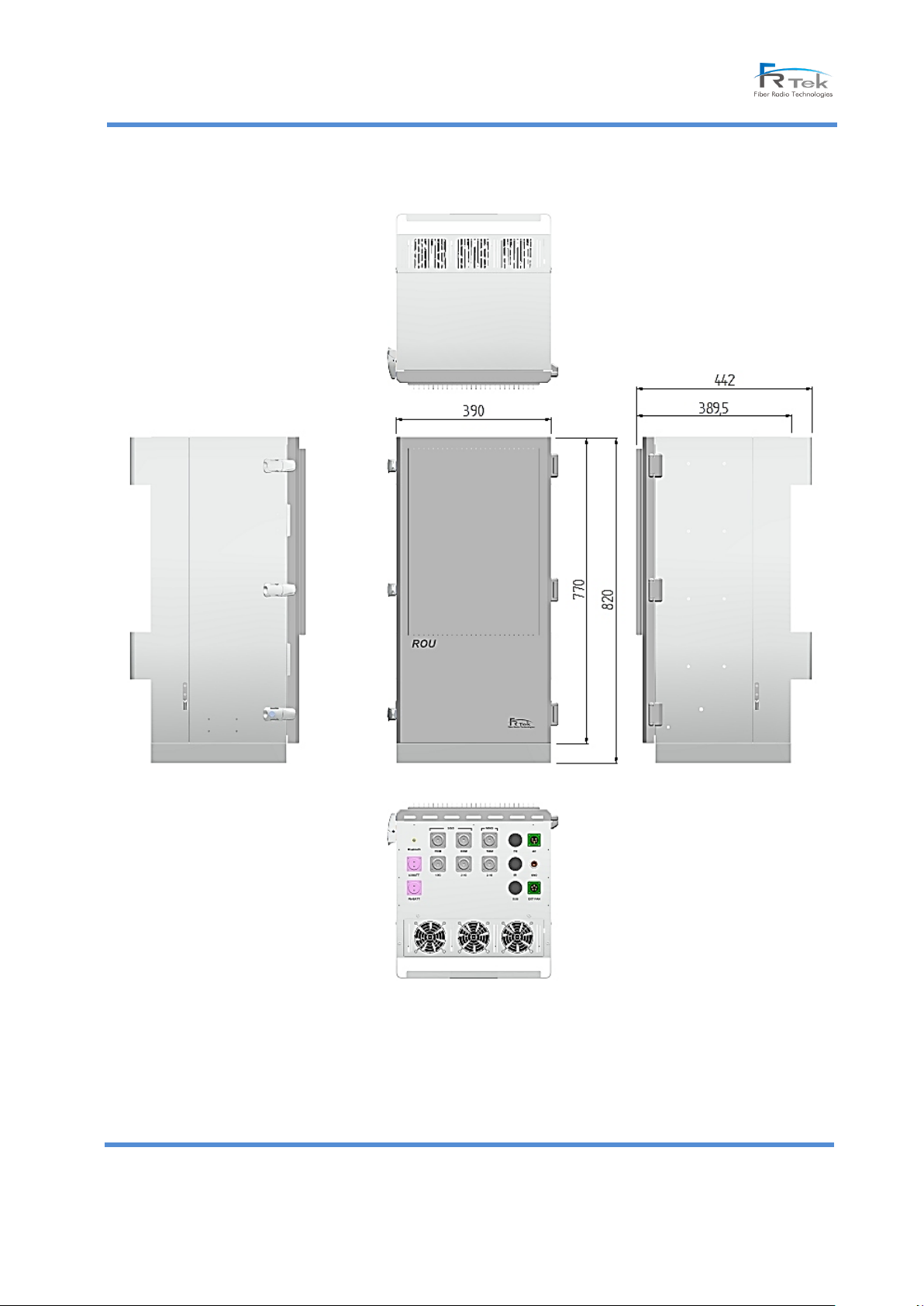
ROU 10W is designed as an indoor type repeater to install it at in-door. Physical dimension is designed to
meet the requirements of user convenience and small installation space. Power supply uses an AC 120V, in case
power failure occurs; it has an battery backup ports with an AWG(American Wire Gauge) 6 ground terminal rug.
External Interface Specifications and size are as follows;
© FRTek Co. Ltd 2015
10
Confidential: Any reproduction or distribution without the express written consent of FRTek Co. Ltd
or FRTek US LLC is strictly prohibited
Page 11
Sierra ROU 10W User Manual
[ROU 10W Front View]
[ROU 10W external appearance]
© FRTek Co. Ltd 2015
11
Confidential: Any reproduction or distribution without the express written consent of FRTek Co. Ltd
or FRTek US LLC is strictly prohibited
Page 12
Sierra ROU 10W User Manual
SPEC
Performance Requirements
Remarks
Frequency Band
TX
728 ~ 757MHz
28MHz, LTE Service
RX
699 ~ 716MHz
777 ~ 787MHz
SPEC
Performance
Requirements
Remarks
Output Level
TX
+40dBm/Total
4W@Operator
4. System Specification
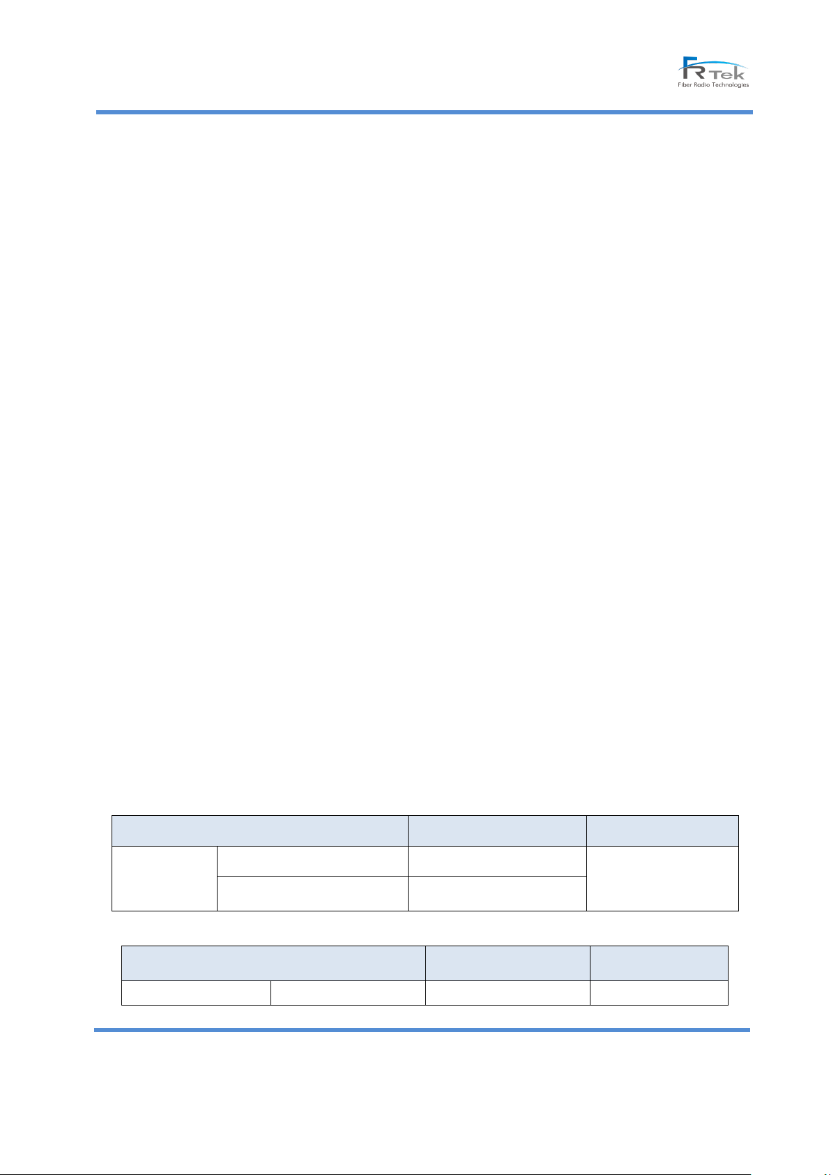
4.1 System Specification
This DAS system is designed for US market and it can support 700MHz SISO/MIMO, 850MHz SISO, 1900MHz SISO,
2100MHz SISO/MIMO and is going to support the 2300MHz SISO/MIMO, 2500MHz SISO/MIMO service(under
development)
Main ROU can support 700MHz, 850MHz, 1900MHz and 2100MHz, Sub ROU can support 2300MHz and
2500MHz signal.
4.1.1 Functional Specification
SIERRA meets the following features and performance features, the details are not specifically mentioned shall
follow functional and performance requirements of “3GPP TS25.1 / TS25.104”, “3GPP TS25.1 / TS25.106”, “3GPP
TS25.1 / TS36.104”.
SIERRA incorporates the following basic functional requirements.
1) MHU is connected with ROUs by optical cable for RF (wired) and ROU shall be installed and operated at
the shade area. LTE, Cellular, PCS, AWS signal transmission between 2 devices will operate through Single-
mode optical fiber. (Optic: supportable for 5.7Gbps)
2) The radio quality of LTE, Cellular, PCS, AWS serviced by SIERRA is the same level as the radio quality of the
base station.
3) When the mobile terminal enters the adjacent base station, SIERRA supports a continuous call (hand
over) of the terminal.
4.1.2 System Specification per Band(ROU10W)
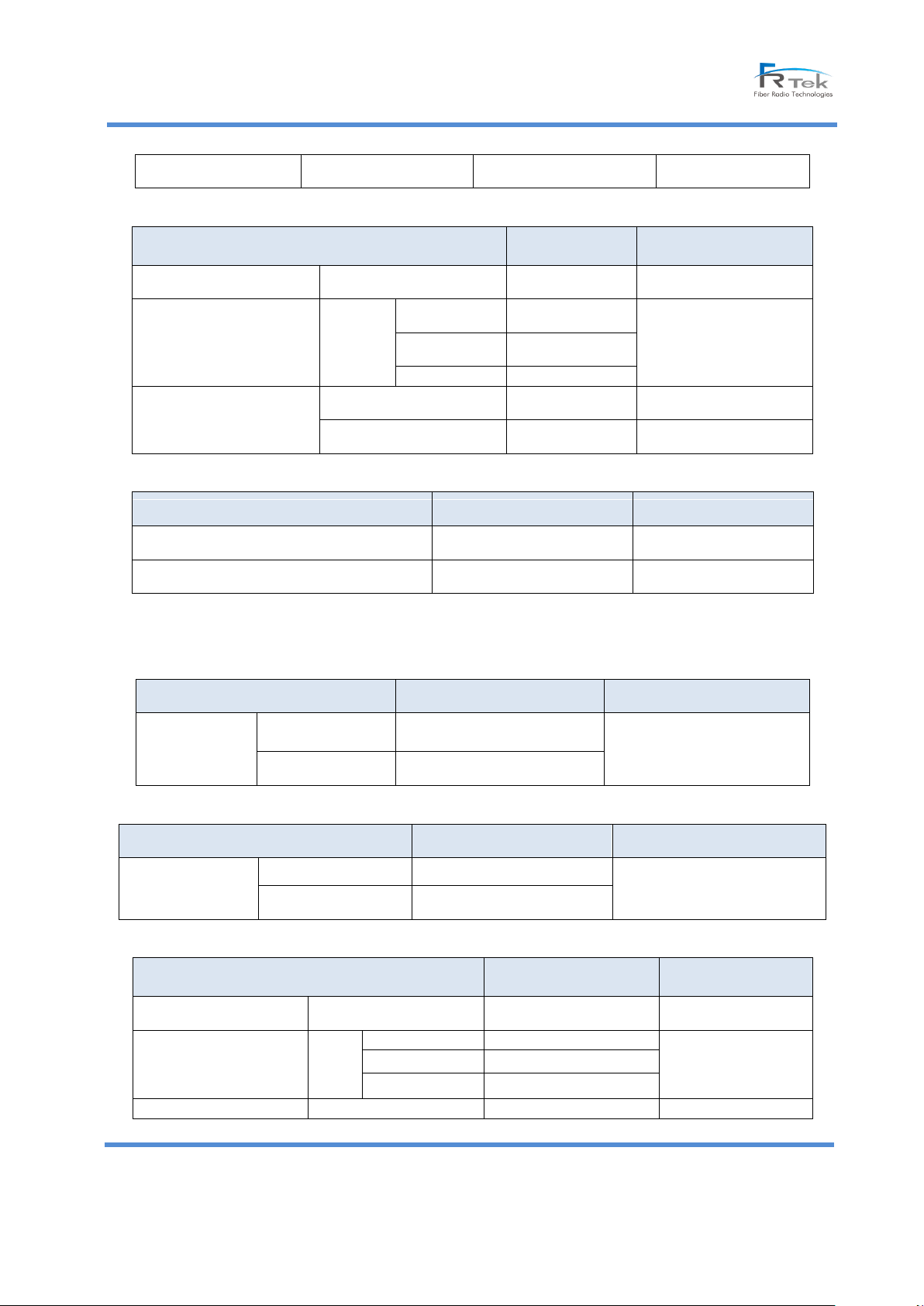
A. 700MHz (28MHz), SISO/MIMO
- Frequency Features
- Output Features
© FRTek Co. Ltd 2015
12
Confidential: Any reproduction or distribution without the express written consent of FRTek Co. Ltd
or FRTek US LLC is strictly prohibited
Page 13
Sierra ROU 10W User Manual
RX
+5dBm/Total
SPEC
Performance
Requirements
Remarks
Noise Figure (NF)
RX
7dB or under
Max Gain
Unwanted emission
features
(within band)
10W
±5.05MHz
-14dBm or under
Max Output
RBW 100KHz
±10.05MHz
-14dBm or under
±15.5MHz
-16dBm or under
ACLR
BW
channel
45dBc
2 * BW
channel
45dBc
SPEC
Performance Requirements
Remark
VSWR
1.5 : 1 or under
TX, RX Separation
100dBc or more
SPEC
Performance Requirements
Remarks
Frequency Band
TX
869~890MHz(862 ~ 868,
891~894MHz N/A)
22MHz(out of 32MHz)
RX
817 ~ 849MHz
SPEC
Performance Requirements
Remarks
Output Level
TX
+40dBm/Total
RX
+5dBm/Total
SPEC
Performance
Requirements
Remarks
Noise Figure(NF)
RX
7dB or under
Max. Gain
Unwanted Emission
Features
(Within band-LTE Signal)
10W
±5.05MHz
-14dBm or under
Max. Output
RBW 100KHz
±10.05MHz
-14dBm or under
±15.5MHz
-16dBm or under
ACLR
BW
channel
45dBc
- Noise Figure and Features
- Other Performance Requirements
B. 850MHz (32MHz), SISO
- Frequency Features
- Output Feature
- Noise Figure and Features
© FRTek Co. Ltd 2015
13
Confidential: Any reproduction or distribution without the express written consent of FRTek Co. Ltd
or FRTek US LLC is strictly prohibited
Page 14
Sierra ROU 10W User Manual
2 * BW
channel
45dBc
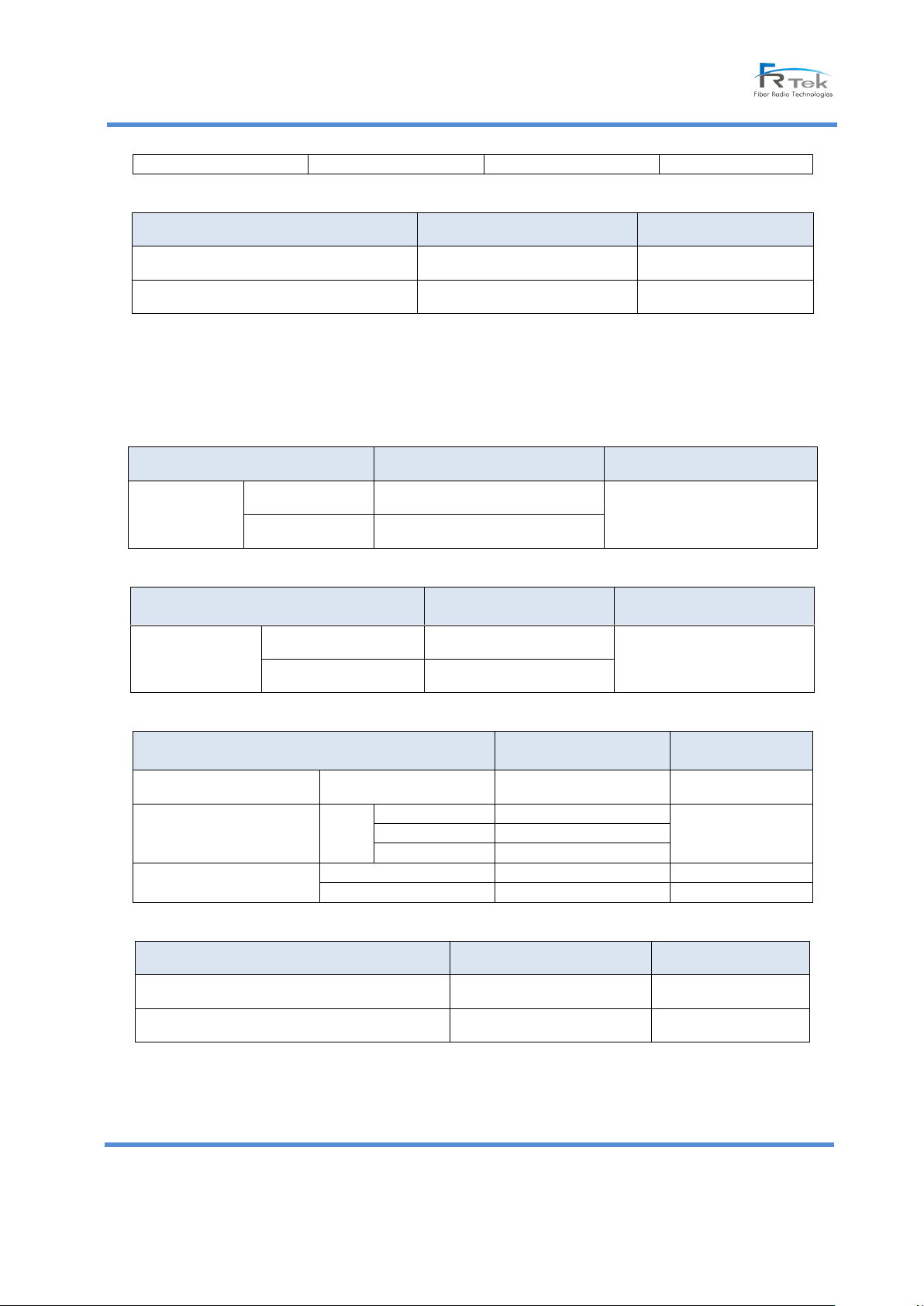
SPEC
Performance Requirements
Remarks
VSWR
1.5 : 1 or under
TX, RX Separation
100dBc or more
SPEC
Performance Requirements
Remarks
Frequency
Band
TX
1930 ~ 1995MHz
65MHz
RX
1850 ~ 1915MHz
SEPC
Performance
Requirements
Remarks
Output Level
TX
+40dBm/Total
RX
+5dBm/Total
SPEC
Performance
Requirements
Remarks
Noise Figure(NF)
RX
7dB or under
Max. Gain
Unwanted Emission
Features
(Within band-LTE Signal)
10W
±5.05MHz
-14dBm or under
Max. Output
RBW 100KHz
±10.05MHz
-14dBm or under
±15.5MHz
-16dBm or under
ACLR
BW
channel
45dBc
2 * BW
channel
45dBc
SPEC
Performance Requirements
Remarks
VSWR
1.5 : 1 or under
RX, TX Separation
100dBc or more
- Other Performance Requirements
C. 1.9GHz (65MHz), SISO
- Frequency Features
- Input/output Features
- Noise Figure and Unwanted Emission Features
- Other Performance Requirements
© FRTek Co. Ltd 2015
14
Confidential: Any reproduction or distribution without the express written consent of FRTek Co. Ltd
or FRTek US LLC is strictly prohibited
Page 15
Sierra ROU 10W User Manual
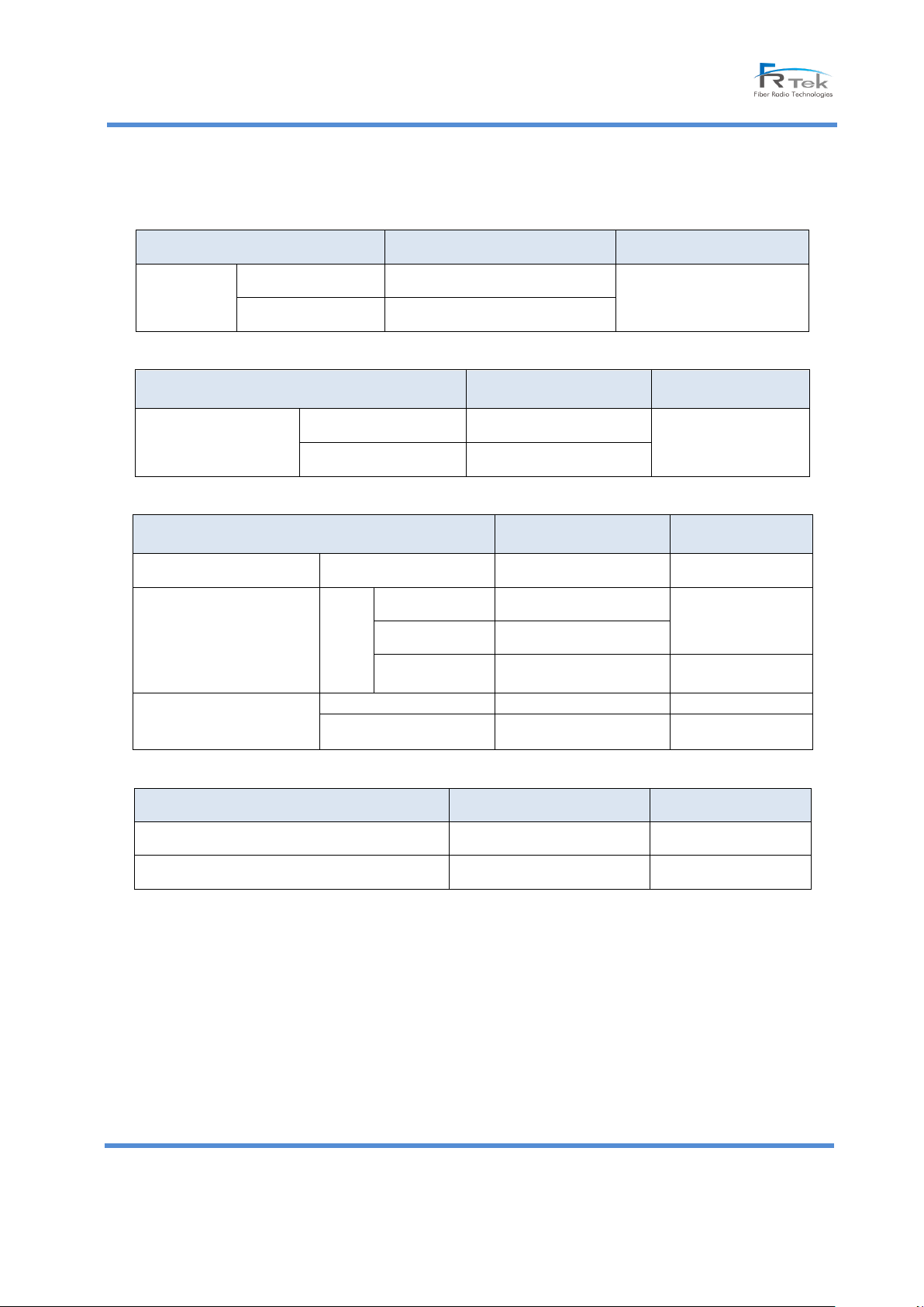
SPEC
Performance Requirements
Remarks
Frequency
Band
TX
2110 ~ 2155MHz
45MHz
RX
1710 ~ 1755MHz
SPEC
Performance
Requirement
Remarks
Output Level
TX
+40dBm/Total
RX
+5dBm/Total
SEPC
Performance
Requirements
Remarks
Noise Figure (NF)
RX
7dB or under
Max. Gain
Unwanted Emission
Features
(Within Band)
10W
±5.05MHz
-14dBm or under
Max. Output
RBW 100KHz
±10.05MHz
-14dBm or under
±15.5MHz
-16dBm or under
Max. Output
RBW 1MHz
ACLR
BW
channel
45dBc
2 * BW
channel
45dBc
SPEC
Performance Requirements
Remarks
VSWR
1.5 : 1 or under
RX, TX Separation
100dBc or more
D. 2.1GHz (45MHz), SISO/MIMO
- Frequency Features
- Output Features
- Noise Figure and Unwanted Emission Features
- Other Performance Requirements
* Standard conditions of the above is 1SET standard each MHU/ROU
© FRTek Co. Ltd 2015
15
Confidential: Any reproduction or distribution without the express written consent of FRTek Co. Ltd
or FRTek US LLC is strictly prohibited
Page 16
Sierra ROU 10W User Manual
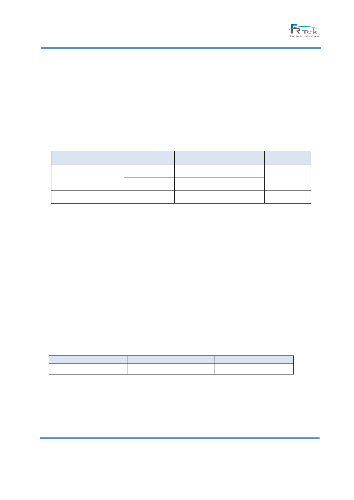
SPEC
Performance Requirements
Remarks
Center wavelength
TX
1270 ± 1nm
RX
1330 ± 1nm
Optical Output Power
- 5 dBm or more
Equipment
Type
Option
ROU 10W
Enclosure Type
Indoor
E. EMS Interface Specification
(1) Protocol : MHU ↔ ROU(Optic)
(2) MHU ↔ ROU (Optic)
(3) ROU ↔ ROU (Optic)
(4) Top surveillance : PC base EMS
(5) Debugger interface: USB2.0(MHU, ROU)
F. Optical characteristic requirements
(1) Transmitter
(2) Receiver
- Receiving element Type: InGaAs PIN Photodiode
- Max receive input range: 0dBm
- Max Rx Sensitivity: -15dBm
(3) Fiber optic cable
- Type: Single-mode fiber
- Loss: 0.25dB/km (1240 ~ 1620nm) or under
4.1.4 Mechanical condition
4.1.4.1 Structure and Shape
- MHU and ROU are to be designed considering the convenience of workers and space of installation site. The
appearance of SIERRA design should be streamlined.
- SIERRA is enabling to use an internal fan, only ROU uses an external fan.
- SIERRA provides a port connected to external battery to ROU.
- RF Connector of MHU is SMA Female and RF Connector of ROU is DIN-Type Female
- Components of the system should be modular. Each component to be fitted to the structure that can be
© FRTek Co. Ltd 2015
16
Confidential: Any reproduction or distribution without the express written consent of FRTek Co. Ltd
or FRTek US LLC is strictly prohibited
Page 17

Sierra ROU 10W User Manual
easily mounted and separated. Replacement and maintenance should be facilitated.
- Each device must be designed as a structure that cannot be dust, contaminants and insects that attack.
- Each device of the system is to be designed to withstand a specified vibration test.
- All parts of the cabinet should be smoothly processed in order to prevent physical damage during
maintenance
- Providing Timing Advance function (0~100us).
4.1.4.2 Manufacturing and Processing
- Sealing material has a strong characteristic to heat, does not tear or damage to the chemical.
- Internal and external wiring are designed as wire wrapping method or a connector connection. A
structure that can withstand the vibrations.
- The printed circuit board is to use the product at least equal to the epoxy resin or glass. Solder is
sophisticated; it is elegant in appearance after soldering. The electrical insulating film treatment is to
prevent a reduction in corrosion and pollution prevention and moisture and insulation resistance due to
the wiring between the accumulations of dust. The manufacturer was consulting us before choosing the
colors.
- Internal and external surfaces of the coating cabinet have a uniform color.
- Exterior of the cabinet is designed to withstand foam (Blistering), exfoliation (Peeling) and cracks for 5
years or more.
- It is designed and manufactured with taking into account the carbon emissions reduced (reduced power
consumption, reduced material use, and so on)
4.1.4.3 Materials and components
- Passive device has a stable characteristic for the frequency and temperature changes. Active element is
industrial or equal to or more semiconductor. The integrated circuit is a solidified device.
- The type of wire is flame retardant coating wire, and SIERRA uses a wire having a sufficient current capacity
and withstand voltage.
- Coaxial cable connected between each of the components is shielded cable coated with aluminum or brass.
- All metal used in the present device are designed to withstand a localized corrosion, including general
corrosion, stress corrosion (Stress Corrosion) and crack (Cracking).
- Plastics being used should not be melt by Solvent and there should be no crack, molting and color when it
exposed to ammonia.
- Plastics should not be cracked when chemical materials which is being used for cable assembly such as filling
compound, insulator, etc.)
© FRTek Co. Ltd 2015
17
Confidential: Any reproduction or distribution without the express written consent of FRTek Co. Ltd
or FRTek US LLC is strictly prohibited
Page 18

Sierra ROU 10W User Manual
- Housing, component, PCB, solder, cable, etc. that are applied to the device shall be in accordance with current
RoHS (Restriction of Hazardous Substances Directive).
-
4.1.5 Electrical conditions
- MHU, ROU operate normally in the commercial power supply (AC120 / 60Hz). (Considering of the
photoelectric composite cable power input)
- ROU can be operated with the external back-up battery only
- The power wiring should be attached to the inside of the door, designed to prevent damage.
- There is a function of overvoltage and overcurrent protection in the DC inputs.
- Withstand voltage is applied to the input and output 3KV for 1 minute, the leakage current is less than 10mA.
- Lleakage current is less than 3.5mA in the phase transition (120V).
- There should be no damage in case of 5 times surge voltage shock - 4kV at AC input port and 4kV at DC input
port.
- Grounding of equipment is separated; communication ground and power ground.
- Fuse must be able to determine whether or not a problem with the naked eye, it can be replaced without
dismantling the equipment.
- All parts used in this repeater meet the conditions of FCC Regulations Title 47, Part 15, Subject J, and EMI Class
B.
- Ground cables equivalent to #6AWG should be installed with a ground table into an enclosure.
4.1.6 Management and monitoring
- SIERRA can be configured up to the GUI for 1pc of MHU,64 pcs ROUs. Status Monitoring and Control is
enabled.
- SIERRA is designed to maintain the previous states such as setting up the device parameters and operating
conditions during recovery after a power outage.
- SIERRA is upper interworking by MHU and EMS Server
- A system control is possible by an operator using a Local GUI or Web GUI.
© FRTek Co. Ltd 2015
18
Confidential: Any reproduction or distribution without the express written consent of FRTek Co. Ltd
or FRTek US LLC is strictly prohibited
Page 19
Sierra ROU 10W User Manual
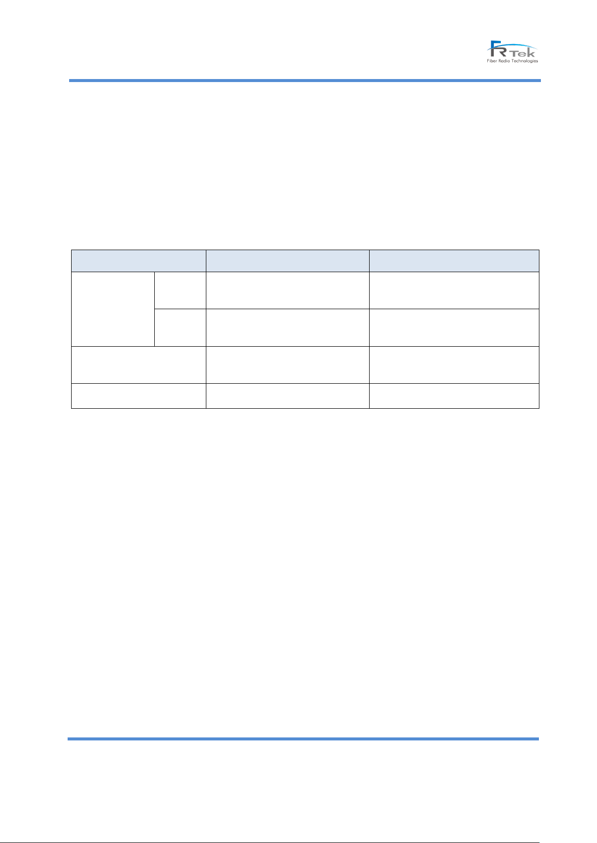
Contents
Performance Requirements
Remark
Operational
environment test
Indoor
- Temp’ : -10 ~ +60C
- Humidity : 0 ~ 95% RH
- Output Change : Within ±3dB
- Internal/external of enclosure has no
changes or problems
Outdoor
- Temp’ : -40 ~ +60C
- Humidity : 0 ~ 95% RH
- Output Change : Within ±3dB
- Internal/external of enclosure has no
changes or problems
Vibration Test
- 10 ~ 150Hz, Gravity Speed 2G
(IEC 60068-2-6)
- System performance is no change
- Internal/external of enclosure has no
changes or problems
Noise Testing
- GR-65-Core(4.6), Level 2
- 65dBA or under
(When use external Fan)
4.2.6 Environmental conditions
- When a specified temperature and humidity test, should not cause any traces of condensation inside the unit.
- Even if not in working order, SIERRA is designed not to be occurring internal condensation and functional
depression.
- When subjected to prescribed vibration test, should not have any performance and mechanical damage of the
system.
- When conducting prescribed waterproof test, the sign of water penetration inside the device should not be.
- MHU environment testing depends on the ambient operating standards
- Environmental test items and items iterations depends on the testing procedure of the business environment.
- Major environmental test conditions are as follows
© FRTek Co. Ltd 2015
19
Confidential: Any reproduction or distribution without the express written consent of FRTek Co. Ltd
or FRTek US LLC is strictly prohibited
Page 20
Sierra ROU 10W User Manual
②
④
③
⑤
⑥
⑦
⑧
⑨
①
5. Operational Program
5. Overview
5.1 Program overview
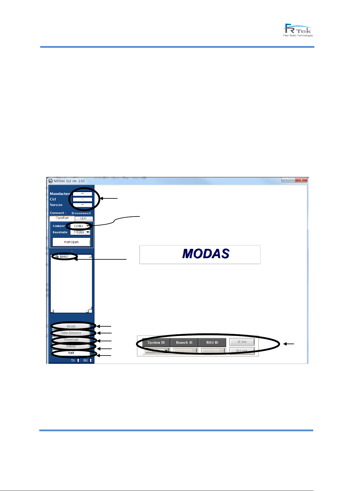
This operational program is designed to monitor and control the SIERRA.
The operational program communicates via the USB-B Type Port of equipment.
5.2 Screen configuration
5.2.1 GUI
This equipment is available to monitor and control via the GUI at the Local.
GUI Configuration, Monitoring, and Control items are shown in the following figure.
(Possible future changes)
[Main Screen]
① Environment Information – Showing equipment manufacturer, control manufacturer and information of
version.
② Tree Information
– Showing the connection status of current equipment.
© FRTek Co. Ltd 2015
20
Confidential: Any reproduction or distribution without the express written consent of FRTek Co. Ltd
or FRTek US LLC is strictly prohibited
Page 21
Sierra ROU 10W User Manual
Items
Unit
Remark
700MHz
Link Path
700MHz / 2.3GHz
Status
Insert
Insert / None
Status
TX Detect AMP
dBm
Status
TX Detect RRFU
dBm
Status
TX ATT
dB
Status/Control
TX FB ATT
dB
Status/Control
TX SD (High)
dBm
Status/Control
TX SD Alarm (High)
Alarm : Red, Normal: Green
Status
TX ALC (High)
dBm
Status/Control
TX ALC (Offset)
dBm
Status/Control
TX SD On/Off (High)
ON/OFF
Status/Control
TX ALC On/Off (High)
ON/OFF
Status/Control
TX ALC On/Off (Offset)
ON/OFF
Status/Control
RX Detect RRFU
dBm
Status
– Green LED signifies regular equipment, Yellow LED equipment signifies Link Fail, Red LED signifies Alarm,
Grey LED signifies equipment.
–When you do double-click of mouse left button, you can check status of equipment.
③ Com Port
– Showing the PC connection port which was connected currently.
– Automatically re-search connected RS-232C port when you click the Refresh.
– When you click Port Open and Port Close, RS-232 Port will do <Connection> and <Close>.
④ Reset – Showing the controller DTU and reset screen of system.
⑤ Time advance setting – Showing Time advance setting.
⑥ Download – Showing CPU F/W Download window per equipment.
⑦ Debug – Showing Debug Screen.
⑧ Exit – Terminate the program.
⑨ ID setting – Read the ID of the connected equipment, and sets the ID.
5.4 ROU Status Verification and Control
[Status Mode] to request information on the Status ROU equipment is 1Sec intervals.
Clicking the [Setup Mode] button at the top, [Set] button is activated. Enter to [Settings mod
e], and now stop the Status Request and to Control the ROU items.
If the setting is successfully completed, [Setting success] message will be shown at the window.
When clicking the [Close] button at the top of the window, the screen is shut down and return to the [GUI Mai
n] screen.
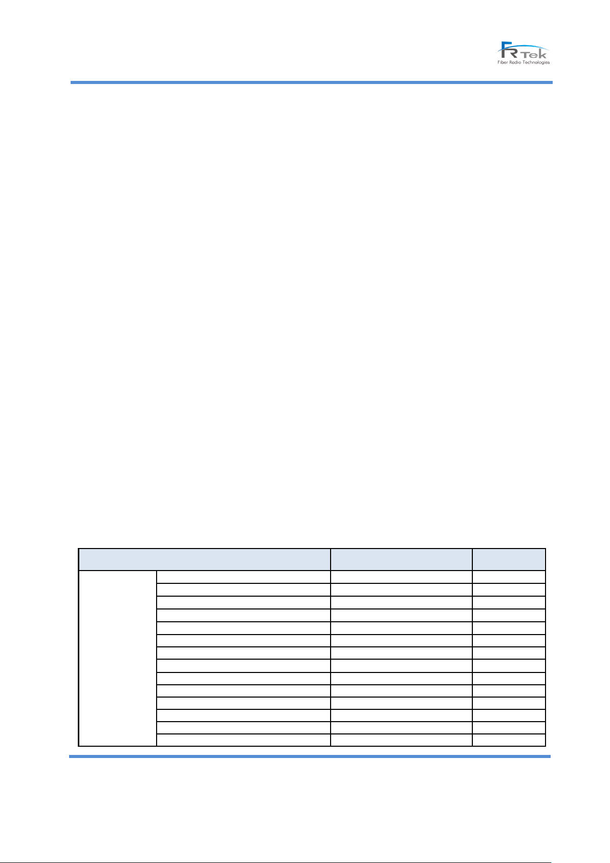
5.4.1 700MHz
- 700MHz Details (SISO – MIMO Items are the same)
© FRTek Co. Ltd 2015
21
Confidential: Any reproduction or distribution without the express written consent of FRTek Co. Ltd
or FRTek US LLC is strictly prohibited
Page 22
Sierra ROU 10W User Manual
RX Detect RRFU 2
dBm
Status
RX ATT
dB
Status/Control
RX ATT 2
dB
Status/Control
Items
Unit
Remark
850MHz
Insert
Insert / None
Status
TX Detect AMP
dBm
Status
TX Detect RRFU
dBm
Status
TX ATT
dB
Status/Control
TX FB ATT
dB
Status/Control
TX SD (High)
dBm
Status/Control
TX SD Alarm (High)
Alarm : Red, Normal: Green
Status
TX ALC (High)
dBm
Status/Control
TX ALC (Offset)
dBm
Status/Control
TX SD On/Off (High)
ON/OFF
Status/Control
TX ALC On/Off (High)
ON/OFF
Status/Control
TX ALC On/Off (Offset)
ON/OFF
Status/Control
RX Detect RRFU
dBm
Status
RX ATT
dB
Status/Control
RX Overpower
Alarm : Red, Normal: Green
Status
10MHz PLL
Alarm : Red, Normal: Green
Status
TX Delay
us
Status/Control
RX Delay
us
Status/Control
Over Power
Alarm : Red, Normal: Green
Status
VSWR
Alarm : Red, Normal: Green
Status
Over Temp
Alarm : Red, Normal: Green
Status
HPA Temp
℃
Status
Amp On/Off
ON/OFF
Status/Control
DTU TX Power (Block SMR ~ Block D)
Status
Items
Unit
Remark
1.9GHz
Insert
Insert / None
Status
TX Detect AMP
dBm
Status
TX Detect RRFU
dBm
Status
TX ATT
dB
Status/Control
TX FB ATT
dB
Status/Control
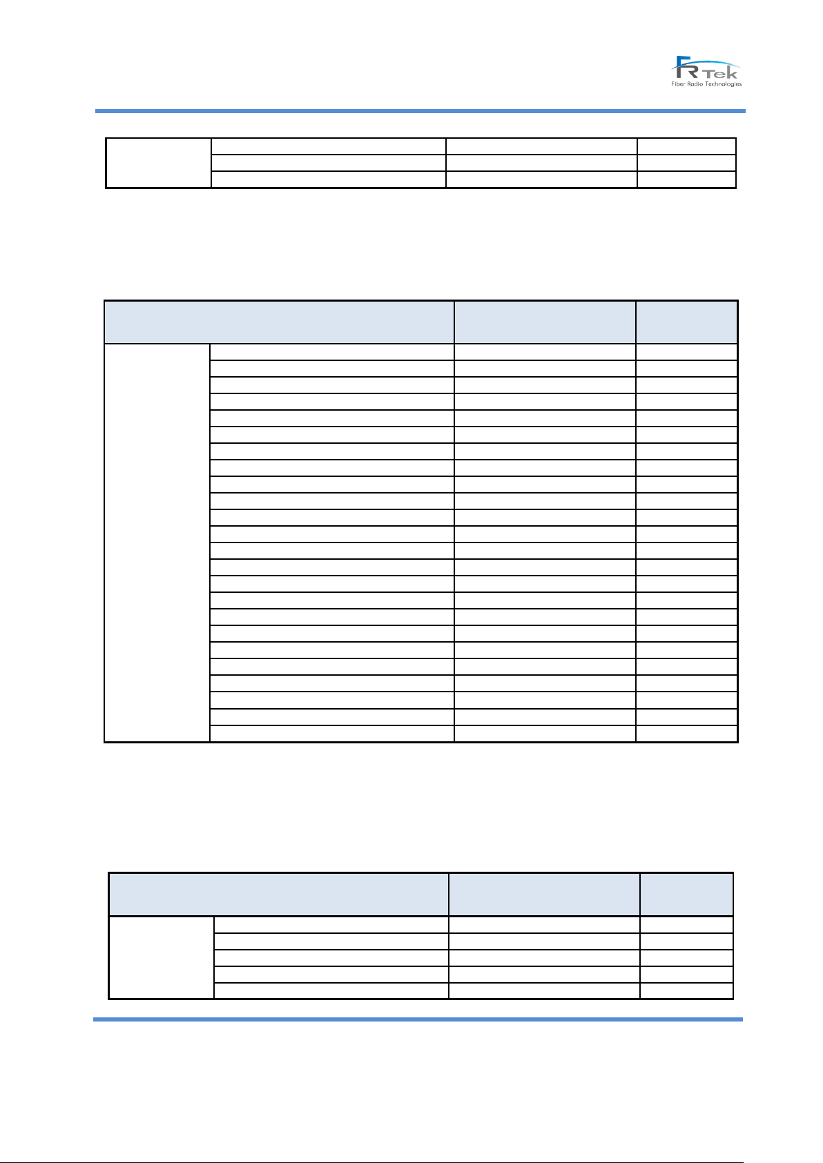
5.4.3 850MHz
- 850MHz Details
[700MHz Details]
-
5.4.4 1.9GHz
- 1.9GHz Details
© FRTek Co. Ltd 2015
22
Confidential: Any reproduction or distribution without the express written consent of FRTek Co. Ltd
or FRTek US LLC is strictly prohibited
[850MHz Details]
Page 23
Sierra ROU 10W User Manual
TX SD (High)
dBm
Status/Control
TX SD Alarm (High)
Alarm : Red, Normal: Green
Status
TX ALC (High)
dBm
Status/Control
TX ALC (Offset)
dBm
Status/Control
TX SD On/Off (High)
ON/OFF
Status/Control
TX ALC On/Off (High)
ON/OFF
Status/Control
TX ALC On/Off (Offset)
ON/OFF
Status/Control
RX Detect RRFU
dBm
Status
RX ATT
dB
Status/Control
RX Overpower
Alarm : Red, Normal: Green
Status
10MHz PLL
Alarm : Red, Normal: Green
Status
TX Delay
us
Status/Control
RX Delay
us
Status/Control
Over Power
Alarm : Red, Normal: Green
Status
Amp On/Off
ON/OFF
Status/Control
DTU TX Power (Block SMR ~ Block D)
Status
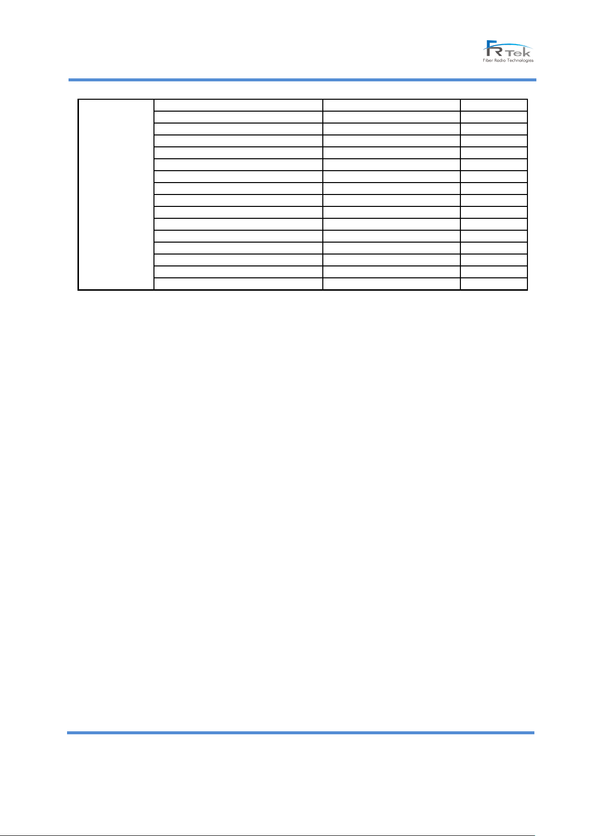
[1.9GHz Details]
5.4.5 2.1GHz
2.1GHz Details (SISO – MIMO Items are the same)
© FRTek Co. Ltd 2015
23
Confidential: Any reproduction or distribution without the express written consent of FRTek Co. Ltd
or FRTek US LLC is strictly prohibited
Page 24
Sierra ROU 10W User Manual
Items
Unit
Remark
2.1GHz
Link Path
2.1GHz / 2.5GHz
Status
Insert
Insert / None
Status
HPA USE
Enable / Disable
Status/Control
TX Detect AMP
dBm
Status
TX Detect RRFU
dBm
Status
TX ATT
dB
Status/Control
TX FB ATT
dB
Status/Control
TX SD (High)
dBm
Status/Control
TX SD Alarm (High)
Alarm : Red, Normal: Green
Status
TX ALC (High)
dBm
Status/Control
TX ALC (Offset)
dBm
Status/Control
TX SD On/Off (High)
ON/OFF
Status/Control
TX ALC On/Off (High)
ON/OFF
Status/Control
TX ALC On/Off (Offset)
ON/OFF
Status/Control
RX Detect RRFU
dBm
Status
RX ATT
dB
Status/Control
RX Overpower
Alarm : Red, Normal: Green
Status
10MHz PLL
Alarm : Red, Normal: Green
Status
TX Delay
us
Status/Control
RX Delay
us
Status/Control
Over Power
Alarm : Red, Normal: Green
Status
VSWR
Alarm : Red, Normal: Green
Status
Over Temp
Alarm : Red, Normal: Green
Status
HPA Temp
℃
Status
Amp On/Off
ON/OFF
Status/Control
DTU TX Power(Block A ~Block F)
Status
[2.1GHz Details]
© FRTek Co. Ltd 2015
24
Confidential: Any reproduction or distribution without the express written consent of FRTek Co. Ltd
or FRTek US LLC is strictly prohibited
Page 25
Sierra ROU 10W User Manual
6. System Installation
6.1 ROU 10W Installation
6.2.1 ROU 10W Configuration
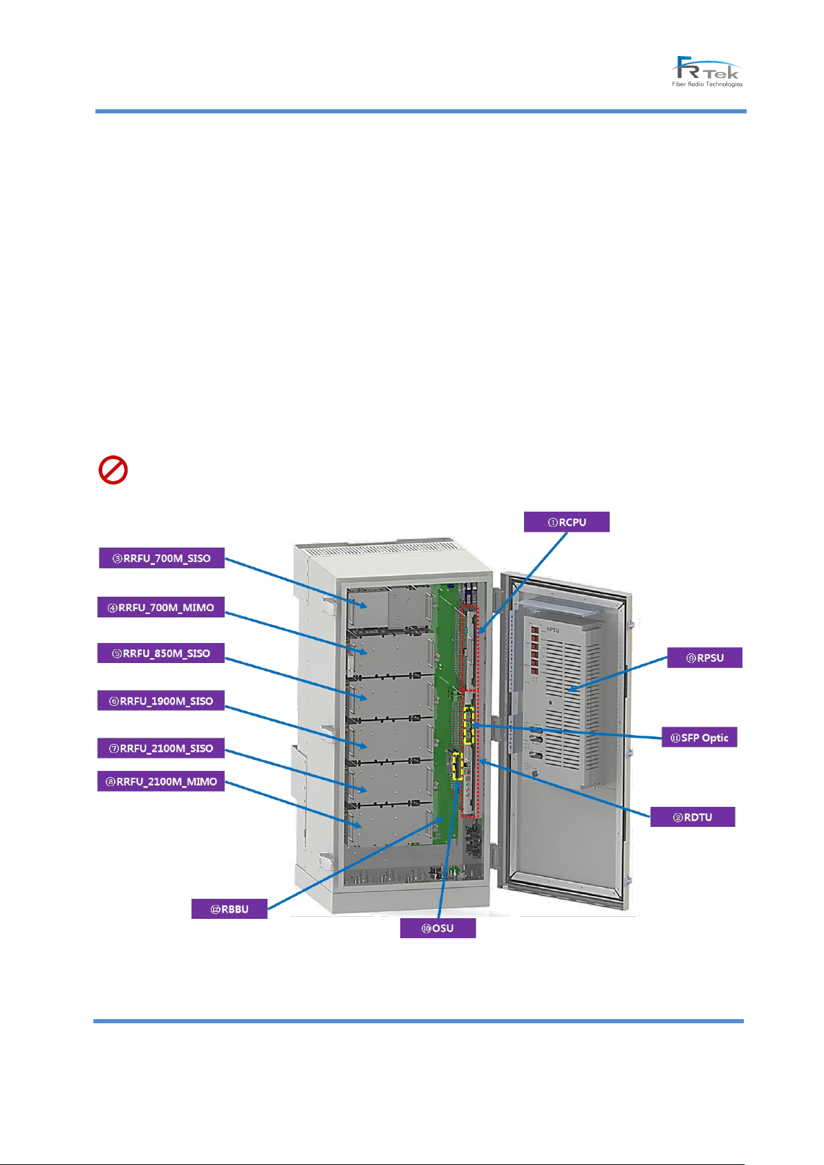
ROU 10W is configured of 6 pcs RF modules, Digital Board, CPU, PSU, Optic Switch and Optic module.
ROU 10W supports 4 bands and expandable to 2 more bands - 700MHz and 2.1GHz with MIMO service
ROU 10W can service up to 4 service providers per each band and the maximum output per band is up to 10W.
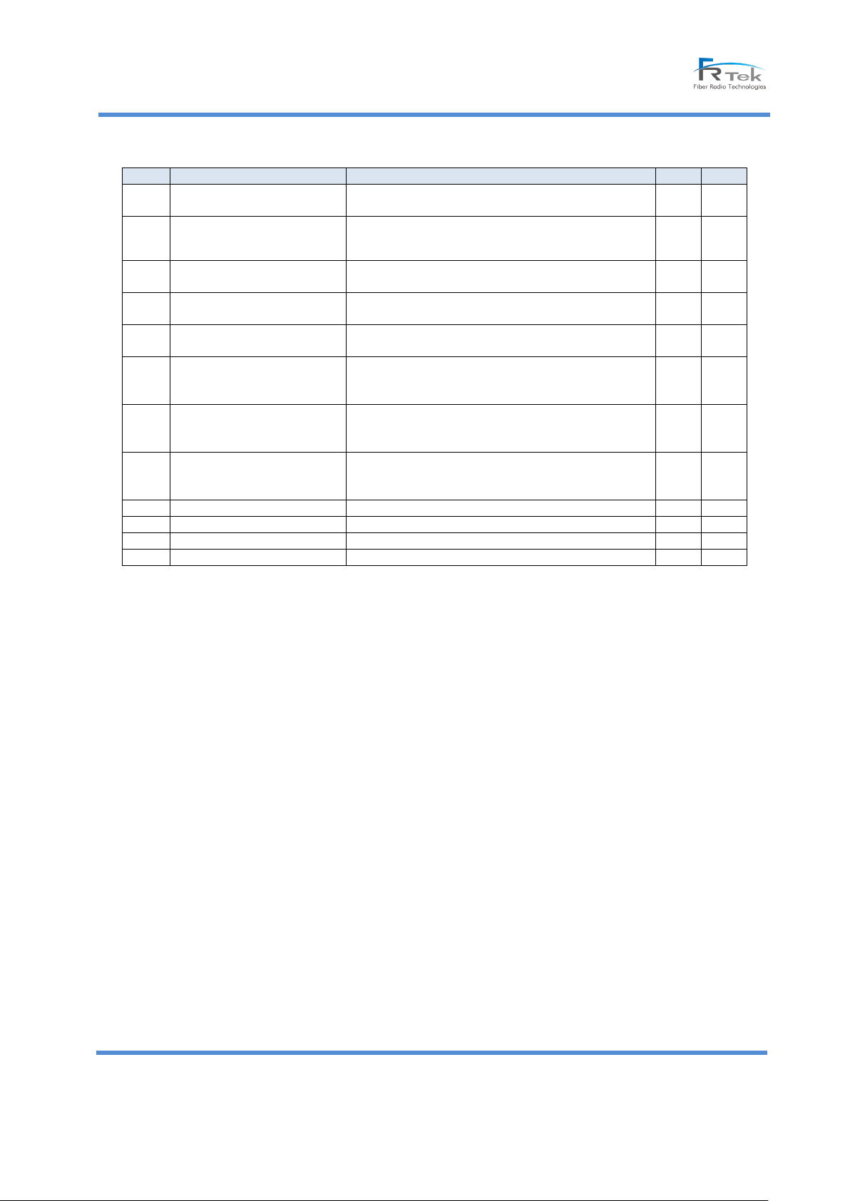
The definition of ROU 10W module is as following.
ROU 10 is powered by AC 120V(55 ~ 65Hz) and it also connects to battery backup port depending on the
installation environment. AC 120V power connector is located under the outdoor enclosure and the connector
recommended is MS3106A-16-10S(F) connecting to power distribution panel.
Maximum output per each service provider shall be limited up to 4W.
[ROU 10W Units Configuration]
© FRTek Co. Ltd 2015
25
Confidential: Any reproduction or distribution without the express written consent of FRTek Co. Ltd
or FRTek US LLC is strictly prohibited
Page 26
Sierra ROU 10W User Manual
NO
Module
Description
Unit
Q’ty
①
RCPU
Monitor and control each modules status, Local GUI &
Web GUI support
EA
1
②
RDTU
Digital Signal Processing(O/E, E/O Conversion), DPD and
Filter Function support
EA
1
③
RRFU_700M_SISO
700M(LTE) TX/RX Signal Amplification and Transmission
Filter, Sub DTU, RF Converter, HPA Unified Structure
EA
1
④
RRFU_700M_MIMO
700M(LTE) TX/RX Signal Amplification and Transmission
Filter, Sub DTU, RF Converter, HPA Unified Structure
EA 1 ⑤
RRFU_850M_SISO
850M(LTE) TX/RX Signal Amplification and Transmission,
Sub DTU, RF Converter, HPA Unified Structure
EA
1
⑥
RRFU_1900M_SISO
1900M(LTE) TX/RX Signal Amplification and
Transmission
Filter, Sub DTU, RF Converter, HPA Unified Structure
EA
1
⑦
RRFU_2100M_SISO
2100M(LTE) TX/RX Signal Amplification and
Transmission
Filter, Sub DTU, RF Converter, HPA Unified Structure
EA 1 ⑧
RRFU_2100M_MIMO
2100M(LTE) TX/RX Signal Amplification and
Transmission
Filter, Sub DTU, RF Converter, HPA Unified Structure
EA
1
⑨
RPSU
Input: AC 120V, Pb, Li-BATT Supported
EA 1 ⑩
OSU
Optical Path Switching Function
EA
1
⑪
SFP Optic
1270/1330nm@10Gbps Optic Signal Transmission
EA 1 ⑫
MBBU
ROU 10W Unit PWR Supply and Signal Interface
© FRTek Co. Ltd 2015
26
Confidential: Any reproduction or distribution without the express written consent of FRTek Co. Ltd
or FRTek US LLC is strictly prohibited
Page 27
Sierra ROU 10W User Manual
6.2.2 ROU 10W Installation
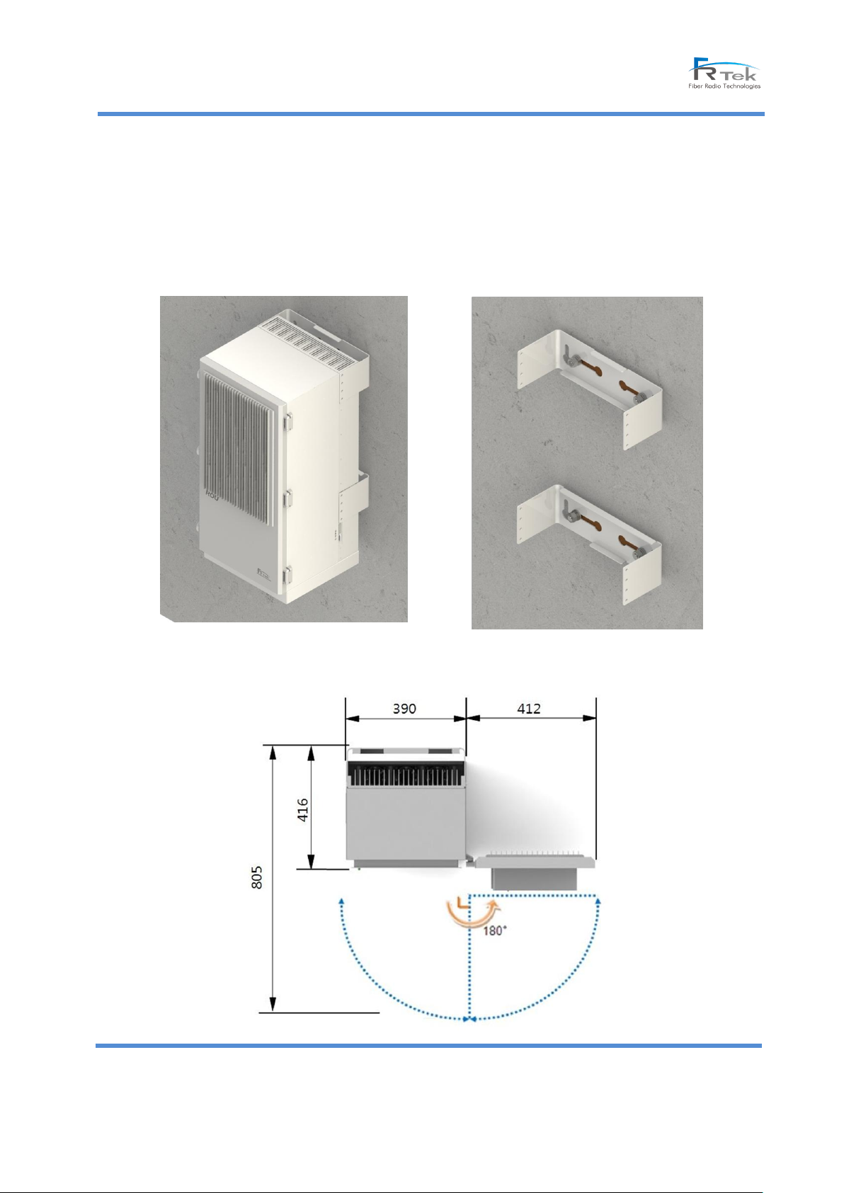
ROU 10W is designed as wall mount type and there shall be 412mm space at the right side of system in order for
easy maintenance in case of door open.
[ROU Wall Mount Installation Picture]
© FRTek Co. Ltd 2015
27
Confidential: Any reproduction or distribution without the express written consent of FRTek Co. Ltd
or FRTek US LLC is strictly prohibited
Page 28
Sierra ROU 10W User Manual
[ROU Open view]
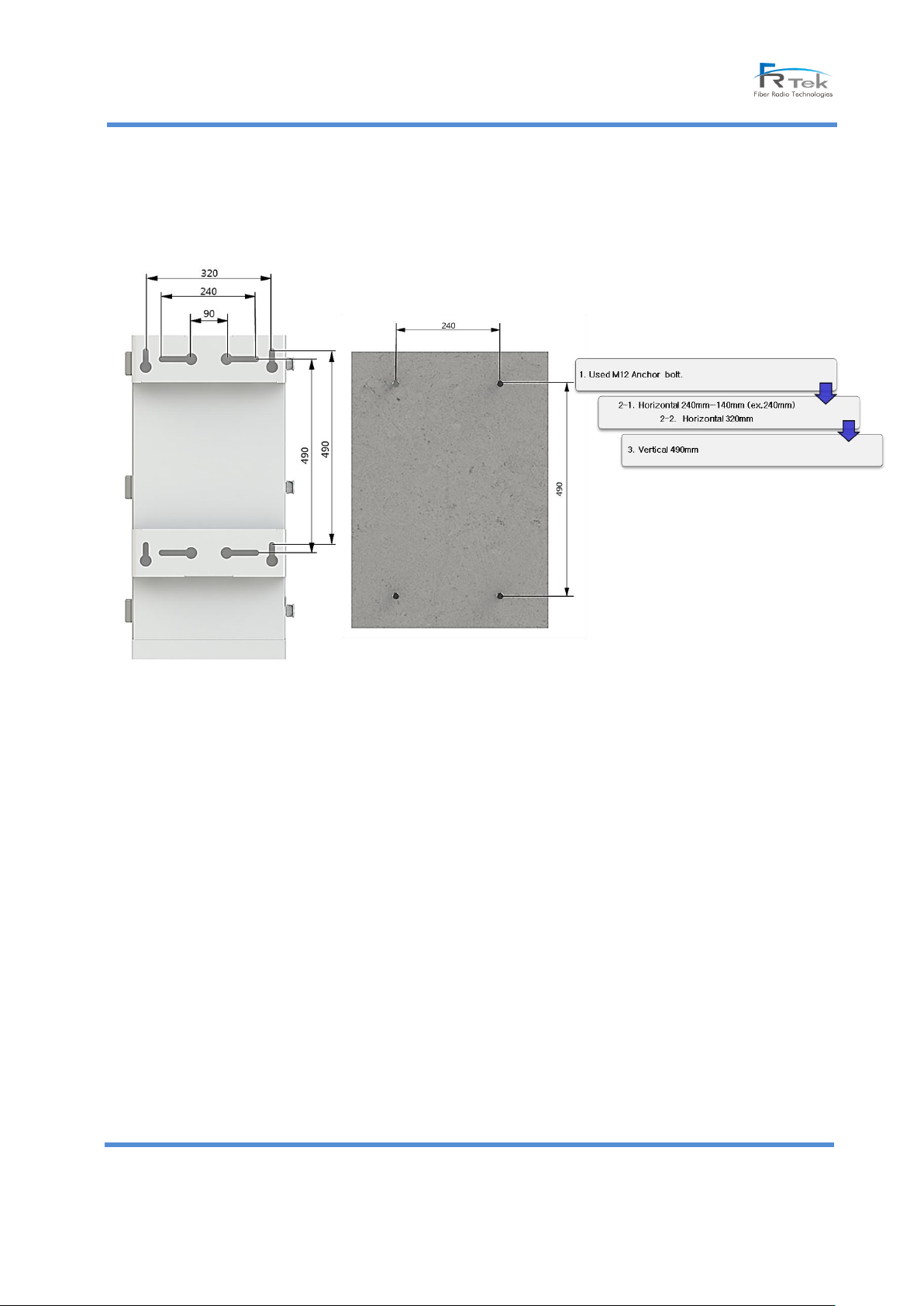
ROU 10W is using an anchor bolt for wall mount installation and is fixed.
The brief picture for wall mounting is as following.
[ROU 10W Anchor bolt Assembly]
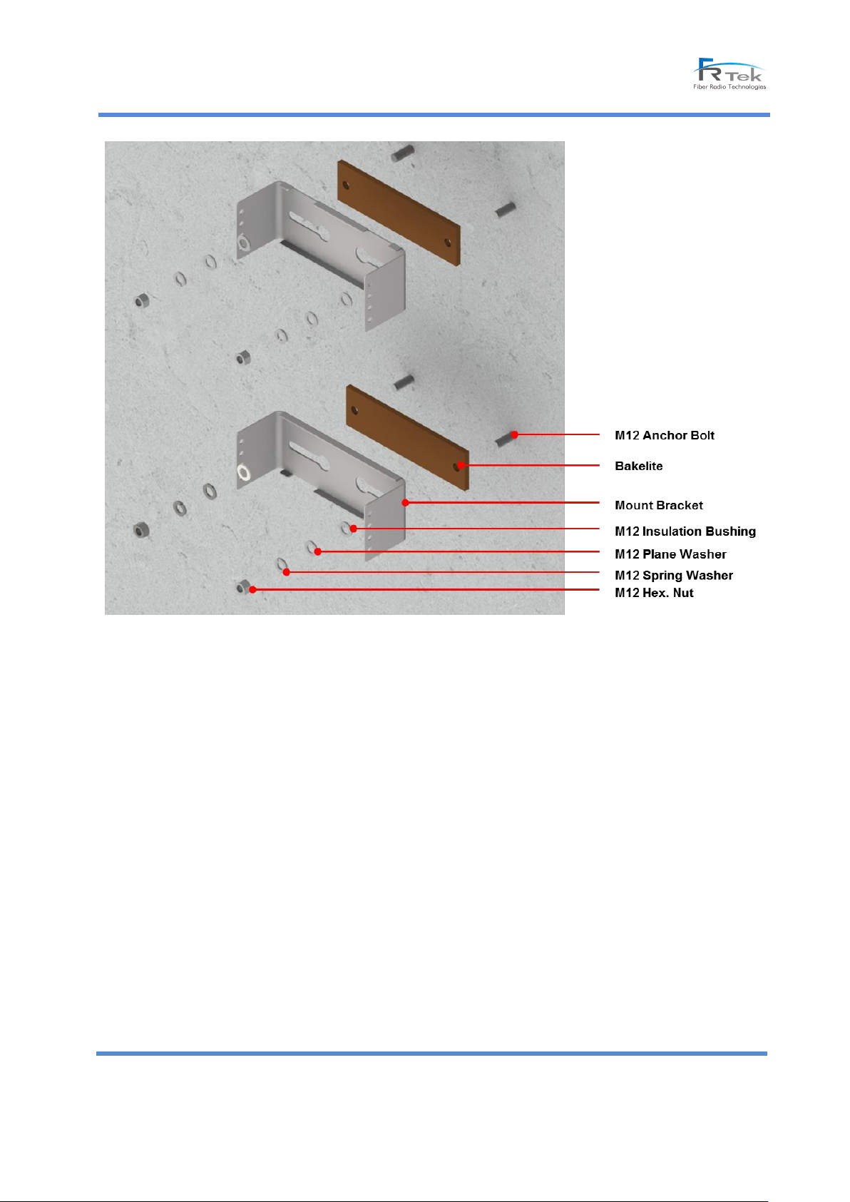
The picture below is mounting bracket assembly drawing for ROU 10W wall mount installation.
Assembly order is as following.
- Insert Bakelite to M12 Anchor bolt.
- Locate ROU 10W in accordance with M12 Anchor bolt.
- Insert M12 Insulation Bushing, M12 Plane washer, M12 Spring washer.
- Tightening them using M12 nut spanner.
© FRTek Co. Ltd 2015
28
Confidential: Any reproduction or distribution without the express written consent of FRTek Co. Ltd
or FRTek US LLC is strictly prohibited
Page 29
Sierra ROU 10W User Manual
[ROU 10W Wall mount Installation Assembly Drawing (Excluding enclosure image) ]
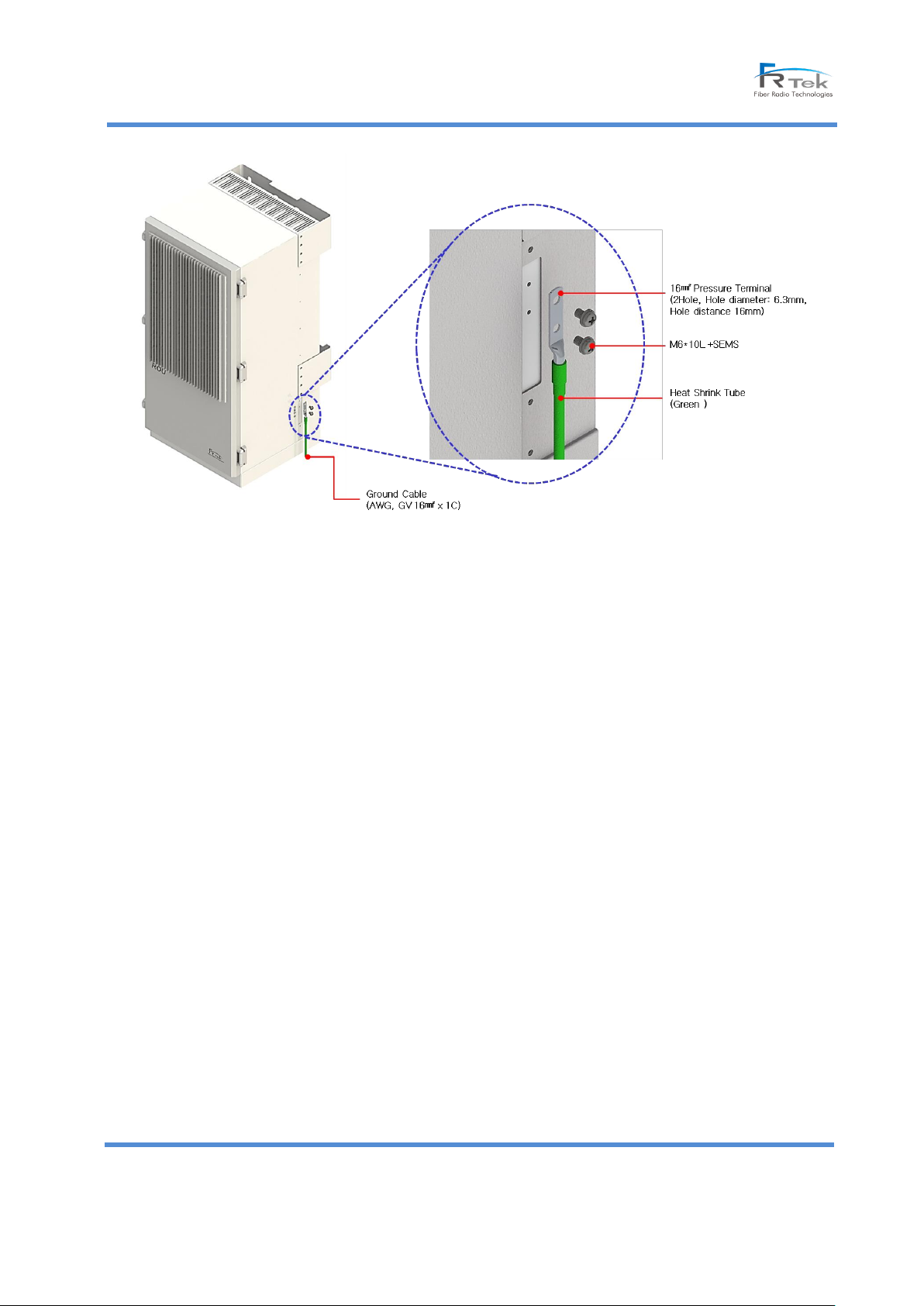
ROU 10W connects the ground of outdoor enclosure and the ground of building for the safety of system from
electricity risk and protects system and system operation.
© FRTek Co. Ltd 2015
29
Confidential: Any reproduction or distribution without the express written consent of FRTek Co. Ltd
or FRTek US LLC is strictly prohibited
Page 30
Sierra ROU 10W User Manual
[ROU 10W Ground Cable Connection ]
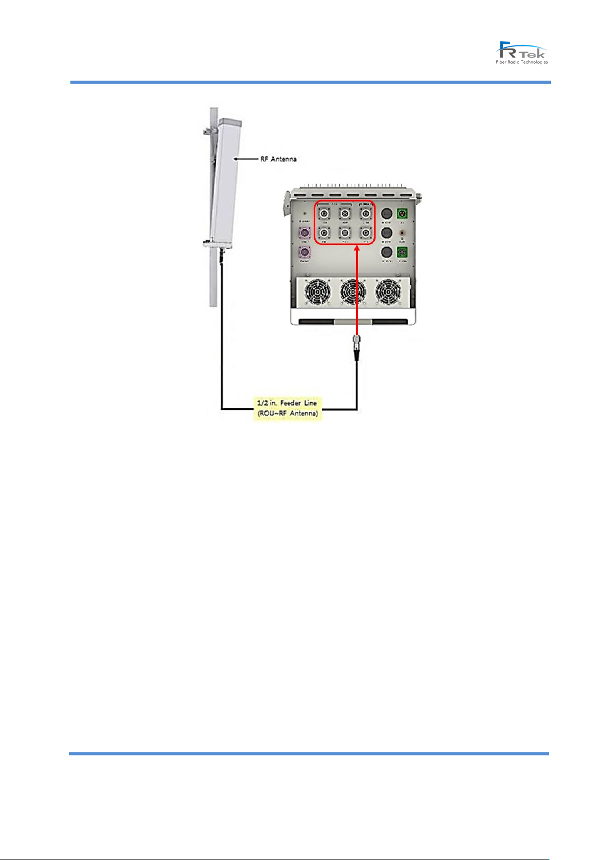
ROU 10W is configured of 6 modules and It has 6 antenna ports assigned for each band at the bottom of the
enclosure.
Antenna port connector type is Din connector and the maximum antenna output port is 10W.
The brief drawing which connects to the antenna of ROU 10W is as following.
Antenna shall be used for ROU 10W by approval of service provider or officially approved and antenna type can be
selective by the installation environment.
© FRTek Co. Ltd 2015
30
Confidential: Any reproduction or distribution without the express written consent of FRTek Co. Ltd
or FRTek US LLC is strictly prohibited
Page 31
Sierra ROU 10W User Manual
[ROU 10W Antenna Cable Connection ]
7. Alarm and Troubleshooting
(1) AC (MHU, ROU)
■ Phenomenon
- PSU LED : PSU AC LED Off
- Alarm window : GREEN → RED
■ Causes
- Input power 120V/AC is not normally enters
■ Appropriate Measures
- Solution : Check the Input power 120V/AC
- Measures : Check the input power 120V/AC, if there is no problems, check the operation by replacing PSU.
(2) DC (MHU, ROU)
■ Phenomenon
- PSU LED : PSU DC LED RED
- Alarm window : GREEN → RED
■ Causes
© FRTek Co. Ltd 2015
31
Confidential: Any reproduction or distribution without the express written consent of FRTek Co. Ltd
or FRTek US LLC is strictly prohibited
Page 32

Sierra ROU 10W User Manual
- PSU output voltage decreases 85% or under
■ Appropriate Measures
- Solution : Replacing PSU
- Measures : Check the operation by repacing PSU
(3) LD Alarm (MHU, ROU)
■ Phenomenon
- Alarm window : GREEN → RED
■ Causes
- LD of optical module is not normal
■ Appropriate Measures
- Solution : Replacing optical module
- Measures : Check the operation by repacing optical module
(4) PD Alarm (MHU, ROU)
■ Phenomenon
- Alarm window : GREEN → RED
■ Causes
- PD of optical module is not normal
■ Appropriate Measures
- Solution : Clean optical connector and check optical cable or replacing optical moduel
- Measures : Clean optical connector, check the optic cable and fix the problem.
If there is no falut, replace the optical module.
(5) TX/RX PLL (MHU, ROU)
■ Phenomenon
- Alarm window : GREEN → RED
■ Causes
- MHU: Has the problem at TX PLL in MUDC(750M/800M/1.9G/2.1G)
- ROU 10W: Has the problem at TX PLL in RRFU intergrated moduel Converter
■ Appropriate Measures
- Solution : MHU- Replacing MRFU(750M/800M/1.8G/2.1G)
ROU - Replacing RRFU intergrated module Converter(750M/800M/1.8G/2.1G)
- Measures : MHU- Check the operation by repacing MUDC(750M/800M/1.8G/2.1G) of Path(alarm occuring)
ROU 10W- Check the operation by repacing RRFU intergrated module
converter(750M/800M/1.8G/2.1G)
(6) Internal FAN (MHU, ROU 10W)
■ Phenomenon
- Alarm window : GREEN → RED
■ Causes
- Occuring some problems at internal fan
© FRTek Co. Ltd 2015
32
Confidential: Any reproduction or distribution without the express written consent of FRTek Co. Ltd
or FRTek US LLC is strictly prohibited
Page 33

Sierra ROU 10W User Manual
■ Appropriate Measures
- Solution : Check and replace the FAN
- Measures : Check the operation by chekcing and repacing the fan
(7) External FAN (MHU, ROU)
■ Phenomenon
- Alarm window : GREEN → RED
■ Causes
- Occuring some problems at external fan
■ Appropriate Measures
- Solution : FAN Check and replace
- Measures : Check the operation by chekcing and repacing the fan
(8) TX S/D(High) (ROU)
■ Phenomenon
- Alarm window : GREEN → RED
■ Causes
- TX output is higher than alarm setting value
■ Appropriate Measures
- Solution : Set appropriate TX ATT
- Measures : Setting the TX ATT in accordance with environment and truning ALC on to prevent to be S/D.
(9) DTU Status (MHU, ROU)
■ Phenomenon
- Alarm window : GREEN → RED
■ Causes
- Occur the problems at harbness connected DTU board or DTU board
■ Appropriate Measures
- Solution : Replacing the harbness connected DTU, if it still has the problem, replace the DTU board
- Measures : Check the operation by replacing the harbness connected DTU or DTU board.
(10) DTU Link Fail (MHU, ROU)
■ Phenomenon
- Alarm window : GREEN → RED
■ Causes
- Occur the problems of link fail between DTU board and CPU
■ Appropriate Measures
- Solution : Check Reference clock or Check the connectivity between DTU board and Back Board
- Measures : Check the connectivity status of DTU board and replace DTU board.
(11) VSWR (ROU)
■ Phenomenon
- Alarm window : GREEN → RED
■ Causes
© FRTek Co. Ltd 2015
33
Confidential: Any reproduction or distribution without the express written consent of FRTek Co. Ltd
or FRTek US LLC is strictly prohibited
Page 34

Sierra ROU 10W User Manual
- Occur the problems at antenna input port or AMP
■ Appropriate Measures
- Solution : Check antenna inputport connection status, if there is no fault, replace the AMP
- Measures : Check the antenna input port and if there is no fault, replace the AMP and confirm it works.
(12) Over Power (ROU)
■ Phenomenon
- Alarm window : GREEN → RED
■ Causes
- Has the problem at RRFU intergrated module output
■ Appropriate Measures
- Solution : Although it set the static output by controling ATT, if it still has the problem, RRFU intergrated
moduled should be replaced
- Measures : Check the operation by chekcing and repacing the RRFU intergrated module
(13) Over Temp (ROU)
■ Phenomenon
- Alarm window : GREEN → RED
■ Causes
- RRFU’s intergrated module temparature is more than 85℃
■ Appropriate Measures
- Solution : Checm the temparatrue table. Even though it is set approprate temarature, still has a problem. APD
AMP should be replaced.
- Measures : Check the operation by replacing the RRFU intergrated module
(14) Battery (ROU)
■ Phenomenon
- Alarm window : GREEN → RED
■ Causes
- Battery has some problems.
■ Appropriate Measures
- Solution : Replacing the Battery
- Measures: Check the operation by replacing the Battery
© FRTek Co. Ltd 2015
34
Confidential: Any reproduction or distribution without the express written consent of FRTek Co. Ltd
or FRTek US LLC is strictly prohibited
 Loading...