

Page 1
1
INOVA DAS Operating Manual
Document Reference
Company: Fiber Radio Technologies
Version: Ver 1.1
Document Status: Release 1
Issue Date: 2019. 03.
Department: R&D Group 2
Author Manager: Jun Hyun, Lee
INOVA DAS
Operating Manual
PRIVATE AND CONFIDENTIAL © 2019 FRTEK CO., LTD.
Page 2
2
INOVA DAS Operating Manual
▪ Copyright
The copyright of this manual is from FRTek Co., Ltd.
This manual may not be reproduced, distributed, modified on any form without the consent of FRTek
Co., Ltd
Unauthorized disclosure, distribution, copying or use of the information contained in this document
in whole or in part without authority is strictly prohibited.
▪ Trademark
The trademarks mentioned in this manual are registered trademarks of the respective company.
Please read this service manual before installation and operation. Use the system only in accordance with contents of this manual.
The specification and information regarding the products in this manual are subject to change due to updates to system functionality or
system revision changes without notice. For the latest revision of this manual or for technical inquiries, please contact below :
Company Address : 181 Metro Drive, Suite 580, San Jose, CA 95110
Homepage : http://www.frtek.com
Contact for technical inquires or troubleshooting.
Telephone : 330-622-2911 or 510-390-1939
PRIVATE AND CONFIDENTIAL © 2019 FRTEK CO., LTD.
Page 3
3
INOVA DAS Operating Manual
Version
Issue Date
Details of Revision
Author
Authorizing
Manager
V 1.0
19. 01. 02.
Original
Jun Hyun, Lee
V 1.1
19. 03. 29.
Original
Jun Hyun, Lee
Revision History
This manual is produced by R&D Group 2 Printed in FRTek.
PRIVATE AND CONFIDENTIAL © 2019 FRTEK CO., LTD.
Page 4

4
INOVA DAS Operating Manual
Contents
Chapter 1. Safety & Certification Notice ..................................................................................................... 8
1.1 FCC/IC Warning Statements ................................................................................................................. 9
1.1.1 FCC Part 15.105 statement ............................................................................................................ 9
1.1.2 FCC Part 15.21 statement .............................................................................................................. 9
1.1.3 Health and Safety Warnings ......................................................................................................... 9
1.1.4 RSS-GEN, Sec. 7.1.2 – (transmitters) .......................................................................................... 10
1.1.5 RSS-GEN, Sec. 7.1.2 – (detachable antennas) .......................................................................... 10
1.1.6 RF Radiation Exposure.................................................................................................................. 11
1.2 Certification Notice .............................................................................................................................. 13
Chapter 2. System Overview ......................................................................................................................... 15
2.1 System Overview .................................................................................................................................. 16
2.1.1 Overview ......................................................................................................................................... 16
2.1.2 INOVA DAS Design Considerations ........................................................................................... 17
2.2 System Network Configuration ......................................................................................................... 19
Chapter 3. System Configuration ................................................................................................................. 21
3.1 ERU Figure and Configuration ........................................................................................................... 22
Chapter 4. System Specification .................................................................................................................. 24
4.1 System Specification ............................................................................................................................ 25
4.1.1 System Specification per Frequency Band – 700MHz ............................................................ 25
4.1.2 System Specification per Frequency Band – 850MHz ............................................................ 26
4.1.3 System Specification per Frequency Band – 1.9GHz .............................................................. 27
4.1.4 System Specification per Frequency Band – 2.1GHz .............................................................. 28
4.1.5 System Specification per Frequency Band – 2.3GHz .............................................................. 29
4.1.6 System Specification per Frequency Band – 2.5GHz .............................................................. 29
4.1.7 System Specification per Frequency Band – 2.6GHz .............................................................. 30
4.2 Organization Specification .................................................................................................................. 31
PRIVATE AND CONFIDENTIAL © 2019 FRTEK CO., LTD.
Page 5

5
INOVA DAS Operating Manual
4.2.1 Structure and Type ........................................................................................................................ 31
4.2.2 Manufacturing and Processing ................................................................................................... 32
4.2.3 Materials and Components ......................................................................................................... 32
4.3 Electrical Specification ......................................................................................................................... 33
4.4 Environmental Specification ............................................................................................................... 33
Chapter 5. System Installation ..................................................................................................................... 35
5.1 Tools ........................................................................................................................................................ 36
5.2 ERU Installation .................................................................................................................................... 38
5.2.1 Product Ceiling Installation ......................................................................................................... 38
5.2.2 Product Wall Installation .............................................................................................................. 39
5.2.3 Antenna Connection ..................................................................................................................... 40
5.3 2.5GHz, 2.6GHz Setting Method ....................................................................................................... 40
Chapter 6. Local GUI(Graphical User Interface) ........................................................................................ 42
6.1 Local GUI Main Screen ........................................................................................................................ 43
6.2 Local GUI ERU Screen .......................................................................................................................... 47
6.2.1 ERU Main Screen ........................................................................................................................... 47
6.2.2 ERU Main Screen per Frequency ................................................................................................ 49
Chapter 7. Alarm and Corrective Action .................................................................................................... 57
7.1 Alarm Phenomenon and Solution ..................................................................................................... 58
PRIVATE AND CONFIDENTIAL © 2019 FRTEK CO., LTD.
Page 6

6
INOVA DAS Operating Manual
Figures
Figure 1. Basic Network Configuration. ................................................................................................................. 19
Figure 2. Extended Network Configuration. ......................................................................................................... 20
Figure 3. ERU Configuration ..................................................................................................................................... 22
Figure 4. ERU Port Configuration. ........................................................................................................................... 23
Figure 5. ERU Ceiling Installation. ........................................................................................................................... 38
Figure 6. ERU Ceiling Installation Assemble. ........................................................................................................ 38
Figure 7. ERU Anchor Bolt Wall Assemble. ........................................................................................................... 39
Figure 8. ERU Wall Installation Assemble. ............................................................................................................. 39
Figure 9. ERU Antenna Connection. ........................................................................................................................ 40
Figure 10. For 2.5GHz Service, Insert 2.5GHz MRFU/ERFU/Multiplexer Module. ........................................ 41
Figure 11. For 2.6GHz Service, Insert 2.6GHz MRFU/ERFU/Multiplexer Module. ........................................ 41
Figure 12. Local GUI Initial Screen. ......................................................................................................................... 43
Figure 13. Local GUI Main Screen. .......................................................................................................................... 44
Figure 14. Spectrum Analyzer Window Screen. ................................................................................................... 45
Figure 15. Time Advance Window Screen. ............................................................................................................ 46
Figure 16. Reset Window Screen. ............................................................................................................................ 46
Figure 17. Download Window Screen. ................................................................................................................... 46
Figure 18. Local GUI ERU Screen. ............................................................................................................................ 47
Figure 19. ERU PIMD Screen. ................................................................................................................................... 48
Figure 20. 700MHz ERU Band Information Screen.............................................................................................. 49
Figure 21. 850MHz ERU Band Information Screen.............................................................................................. 50
Figure 22. 1.9GHz ERU Band Information Screen. ............................................................................................... 51
Figure 23. 2.1GHz ERU Band Information Screen. ............................................................................................... 52
Figure 24. 2.3GHz ERU Band Information Screen. ............................................................................................... 53
Figure 25. 2.5GHz ERU Band Information Screen. ............................................................................................... 54
Figure 26. 2.6GHz ERU Band Information Screen. ............................................................................................... 55
PRIVATE AND CONFIDENTIAL © 2019 FRTEK CO., LTD.
Page 7

7
INOVA DAS Operating Manual
Used Abbreviations
DAS Distributed Antenna System
EMS Element Management System
MHU Master Hub Unit
EHUB Ethernet HUB unit
ERU Ethernet Remote Unit
PSU Power Supply Unit
ERFU ERU RF Unit
SFP The Small form-Factor Pluggable
GUI Graphical User Interface
SISO Single Input Single Output
SMR Specialized Mobile Radio
TBD To Be Determined
USB Universal Serial Bus
VSWR Voltage Standing Wave Ratio
ACLR Adjacent Channel Leakage Power Ratio
ALC Auto Level Control
EVM Error Vector Magnitude
3GPP 3rd Generation Partnership Project
PRIVATE AND CONFIDENTIAL © 2019 FRTEK CO., LTD.
Page 8

8
INOVA DAS Operating Manual
Chapter 1
Safety & Certification Notice
1.1 FCC/IC Warning Statements
1.2 Certification Notice
PRIVATE AND CONFIDENTIAL © 2019 FRTEK CO., LTD.
Page 9

9
INOVA DAS Operating Manual
Safety & Certification Notice
1.1 FCC/IC Warning Statements
1.1.1 FCC Part 15.105 statement
This equipment has been tested and found to comply with the limits for a Class A digital device,
pursuant to part 15 of the FCC Rules. These limits are designed to provide reasonable protection against
harmful interference when the equipment is operated in a commercial environment. This equipment
generates, uses, and can radiate radio frequency energy and, if not installed and used in accordance
with the instruction manual, may cause harmful interference to radio communications. Operation of
this equipment in a residential area is likely to cause harmful interference in which case the user will
be required to correct the interference at his own expense.
1.1.2 FCC Part 15.21 statement
Any changes or modifications not expressly approved by the party responsible for compliance could
void the user's authority to operate this equipment
1.1.3 Health and Safety Warnings
- This system can be operated by approved operator only and operator should observe the warning
sentence of operating manual.
- The operator who can install, operate or handle related system service should acquaint themselves
this manual.
- Control and configuration of this system should be set up according to purpose of use (Refer to the
manufacturer’s product information), it has to be satisfied prescribed request items.
- Operator should turn off the main power switch before installing system, maintenance and related
works.
- If this product is disassembled intentionally, it can bring electric shock, breakdown, malfunction and
static with losing life and property. Do not disassemble, repair and modify product.
- This system cover should be (door) securely fastened in open position, e.g. by tying it up, at outdoor
work in order to prevent door from slamming due to wind causing bodily harm or damage.
PRIVATE AND CONFIDENTIAL © 2019 FRTEK CO., LTD.
Page 10

10
INOVA DAS Operating Manual
- Due to power dissipation, the remote unit may reach a very high temperature. Do not operate this
equipment on or close to flammable materials. Use caution when servicing the unit.
- Use this equipment only for the purpose specified by the manufacturer. Do not carry out any
modifications or fit any spare parts, which are not sold or recommended by the manufacturer. This
could cause fires, electric shock or other injuries.
- Read and obey all the warning labels attached to the unit. Make sure that all warning labels are
kept in a legible condition.
- It is the responsibility of the network provider to implement prevention measures to avoid health
hazards associated with radiation from the antenna(s) connected to the unit.
- Do not use any solvents, chemicals, or cleaning solutions containing alcohol, ammonia, or abrasives.
- Although the remote unit is internally protected against overvoltage, it is strongly recommended to
ground (earth) the antenna cables close to the repeater’s antenna connectors for protection against
atmospheric discharge.
- Antenna(s) must be installed such that a minimum separation distance of at least 20cm is
maintained between the radiator (antenna) and all persons at all times. This device must not be co-
located or operating in conjunction with any other antenna or transmitter.
1.1.4 RSS-GEN, Sec. 7.1.2 – (transmitters)
Under Industry Canada regulations, this radio transmitter may only operate using an antenna of a
type and maximum (or lesser) gain approved for the transmitter by Industry Canada. To reduce potential
radio interference to other users, the antenna type and its gain should be so chosen that the equivalent
isotropically radiated power (e.i.r.p.) is not more than that necessary for successful communication.
Conformément à la réglementation d’Industrie Canada, le présent émetteur radio peut
fonctionneravec une antenne d’un type et d’un gain maximal (ou inférieur) approuvé pour l’émetteur
par Industrie Canada. Dans le but de réduire les risques de brouillage radioélectrique à l’intention
desautres utilisateurs, il faut choisir le type d’antenne et son gain de sorte que la puissance
isotroperayonnée quivalente (p.i.r.e.) ne dépassepas l’intensité nécessaire à l’établissement d’une
communication satisfaisante.
1.1.5 RSS-GEN, Sec. 7.1.2 – (detachable antennas)
PRIVATE AND CONFIDENTIAL © 2019 FRTEK CO., LTD.
Page 11
11
INOVA DAS Operating Manual
This radio transmitter (identify the device by certification number, or model number if Category II)has
been approved by Industry Canada to operate with the antenna types listed below with the maximum
permissible gain and required antenna impedance for each antenna type indicated. Antenna types not
included in this list, having a gain greater than the maximum gain indicated for that type, are strictly
prohibited for use with this device.
Le présent émetteur radio (identifier le dispositif par son numéro de certification ou son numéro de
modèle s’il fait partie du matériel de catégorie I) a été approuvé par Industrie Canada pour fonctionner
avec les types d’antenne énumérés ci-dessous et ayant un gain admissible maximal et l’impédance
requise pour chaque type d’antenne. Les types d’antenne non inclus dans cette liste,ou dont le gain est
supérieur au gain maximal indiqué, sont strictement interdits pour l’exploitation de l’émetteur.
1.1.6 RF Radiation Exposure
This equipment complies with RF radiation exposure limits set forth for an uncontrolled environment.
This equipment should be installed and operated with a minimum distance of 20 cm between the
radiator and your body. This transmitter must not be co-located or operating in conjunction with any
other antenna or transmitter. RF exposure will be addressed at time of installation and the use of higher
gain antennas require larger separation distances.
L’antenne (ou les antennes) doit être installée de façon à maintenir à tout instant une distance
minimum de au moins 20 cm entre la source de radiation (l’antenne) et toute personne physique. Cet
appareil ne doit pas être installé ou utilisé en conjonction avec une autre antenne ou émetteur.
Warning
Obey all general and regional installation and safety regulations relating to work on high
voltage installations, as well as regulations covering correct use of tools and personal protective
equipment.
Warning
Use of unauthorized antennas, cables, and /or coupling devices not conforming with ERP/EIRP
and /or indoor‐only restrictions is prohibited.
PRIVATE AND CONFIDENTIAL © 2019 FRTEK CO., LTD.
Page 12
12
INOVA DAS Operating Manual
The head end unit must always be connected to the Base Station using a direct cabled connection.
This system has not been approved for use with a wireless connection via server antenna to the
base station.
When external fan installed in the bottom of the enclosure operate,
please keep at regular intervals to prevent danger.
If you want to detach it, you must have access after operation of fan off.
WARNING. This is NOT a CONSUMER device. It is designed for installation by FCC LICENSEES
and QUALIFIED INSTALLERS. You MUST have an FCC LICENSE or express consent of an FCC
License to operate this device. Unauthorized use may result in significant forfeiture penalties,
including penalties in excess of $100,000 for each continuing violation.
WARNING: This is NOT a CONSUMER device. It is designed for installation by an installer
approved by an ISED licensee. You MUST have an ISED LICENCE or the express consent of an
ISED licensee to operate this device.
Warning
Laser radiation! Do not stare into the beam; do not view it directly or with optical instruments.
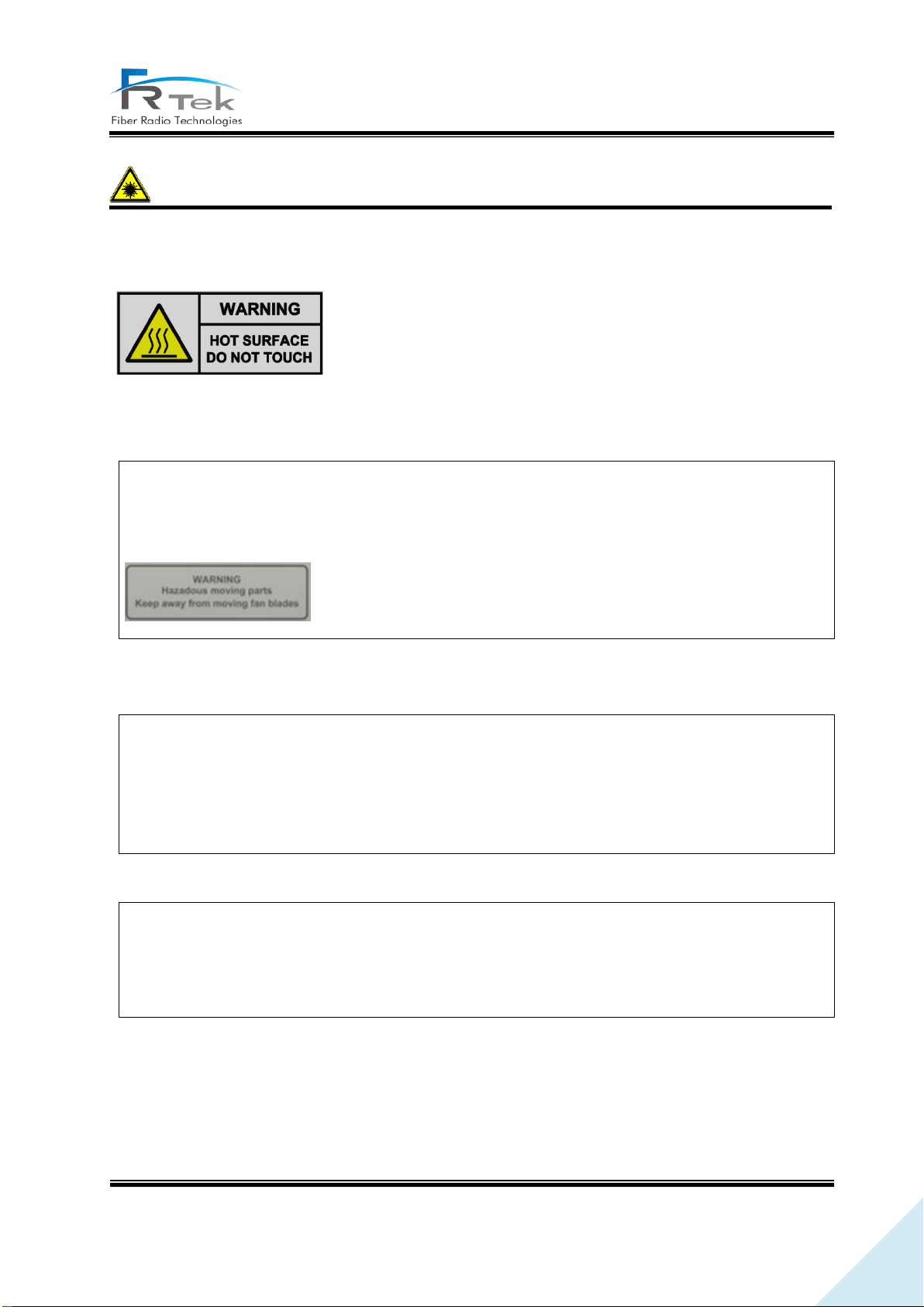
Please be informed that the temperature of the surface is too high. Please
be careful. The label is attached to the front of the equipment and the
PSU (Power Supply Unit).
• INFORMATION TO THE USER
• [FCC] BOOSTER WARNING LABEL
• [IC] BOOSTER WARNING LABEL
• NOTICE
PRIVATE AND CONFIDENTIAL © 2019 FRTEK CO., LTD.
Page 13

13
INOVA DAS Operating Manual
This equipment’s simple information are :
- AMP Gain : 42dB @700M, 850M / 44dB @1.9G, 2.1G / 40dB @2.3G / 43dB @2.5G, 2.6G
- Bandwidth : 28MHz @700M / 32MHz @850M / 65MHz @1.9G / 70MHz @2.1G / 10MHz @2.3G
195M @2.5G / 70MHz @2.6G
- Output Power: 21dBm @700M, 850M, 2.3G / 24dBm @1.9G, 2.1G, 2.5G, 2.6G
- Input/Output impedances : 50ohm
1.2 Certification Notice
Specification or recommendation about Antennas is not available or not mention in this manual. As
per default antennas, cables or coupling devices, contact www.frtek.com for further information.
For PLUGGABLE EQUIPMENT, the socket‐outlet shall be installed near the equipment and shall be
easily accessible.
- FCC : This equipment complies with the applicable sections of Title 47 CFR Rule Parts
- UL : This equipment complies with UL Standard for safety for information technology equipment,
including electrical business equipment.
- FDA/CDRH : This equipment uses a LASER according to FDA/CDRH Rules. This product conforms to
all applicable standards of 21 CFR Chapter 1, Subchapter J, Part 1040.
Note
RESTRICTED ACCESS LOCATION: location for equipment where both of the following apply:
- access can only be gained by SERVICE PERSIONS or by USERS who have been instructed about
the reason for the restrictions applied to the location and about any precautions that shall be
taken; and
- access is through the use of a TOOL or lock and key, or other means of security, and is controlled
PRIVATE AND CONFIDENTIAL © 2019 FRTEK CO., LTD.
Page 14

14
INOVA DAS Operating Manual
by authority responsible for the location
- Home/ personal use are prohibited
PRIVATE AND CONFIDENTIAL © 2019 FRTEK CO., LTD.
Page 15

15
INOVA DAS Operating Manual
Chapter 2
System Overview
2.1 System Overview
2.2 System Network Configuration
PRIVATE AND CONFIDENTIAL © 2019 FRTEK CO., LTD.
Page 16

16
INOVA DAS Operating Manual
System Overview
2.1 System Overview
2.1.1 Overview
INOVA DAS is a system that can provide high quality telecommunication quality and data
telecommunication service both in-building and outdoor. Also, this system is a DAS (Distributed
Antenna System) system, a digital system capable of accommodating a plurality of frequency bands,
available for public and private facilities.
INOVA DAS system can be installed in:
- Shopping Malls
- Hotels
- Campus
- Airports
- Subways
- Stadiums and convention centers, etc
INOVA DAS helps improve poor telecommunication in-building/outdoor wireless environments. This
system provides telecommunication service to every corner of the building, and allows the user to use
telecommunication service regardless of the location. Also, INOVA DAS supports worldwide
telecommunication standards and public interface protocols.
System capable frequencies :
- 700MHz(LTE)
- 850MHz(CDMA, UMTS, LTE)
- 1.9GHz(UMTS, LTE)
- 2.1GHz(UMTS, LTE)
- 2.3GHz(LTE)
- 2.5GHz(TD-LTE) or 2.6GHz(LTE)
INOVA DAS is configured with standardized modules. The coverage of specific frequency band can
be ensured by mounting the unit module of the frequency. Also, since multiple signals can be
transmitted through optic cable, additional hardware modification is not needed.
PRIVATE AND CONFIDENTIAL © 2019 FRTEK CO., LTD.
Page 17
17
INOVA DAS Operating Manual
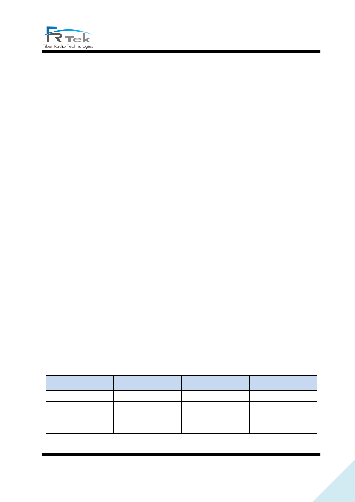
INOVA DAS
Model Name
Type
Remark
MHU
FR-RLWFMHUUC
19” Rack type
EHUB
FR-RLWFEHUBUC
Wall mount type
ERU
FR-RLWFDL24UC
Ceiling mount type
Available for wall
mount
The main characteristics and features of INOVA DAS can be summarized as below.
• Scalability
- Supports optic fiber port.
- Star or cascade structure of network configuration is available.
- in-building or outdoor service is available.
- EMS support of remote control/monitoring for all network configured MHU, EHUB, and ERU.
• Structure
- Modular frequency upgrade.
- Plug-in type module.
• Multi-band, multi-operator support
- One ERU supports up to 6 frequency band service.
- 2.6GHz frequency band service for Canada operators available.
- Multi-operator support for one frequency band available.
• Low OPEX / CAPEX
- Miniaturized design.
- Easy installation and maintenance.
• Technology improvements
- RF direct conversion technology by applying RF 1Chip.
- Sectorization function for Alpha or Beta sector service.
- 1Gbps Ethernet telecommunication function available for various applications.
- Node Isolation function implementation to prevent service disconnection of lower node. (EHUB)
2.1.2 INOVA DAS Design Considerations
INOVA DAS is configured as below, and the model name is as the following.
PRIVATE AND CONFIDENTIAL © 2019 FRTEK CO., LTD.
Page 18
18
INOVA DAS Operating Manual
Service Band
Remark
MHU
EHUB
ERU
700MHz
850MHz
1.9GHz
2.1GHz
2.3GHz
2.5GHz or 2.6GHz
USA : 2.5GHz support
Canada : 2.6GHz support
ITEM
MHU
EHUB
ERU
Input Power
88V~132V (60Hz)
88V~132V (60Hz)
PoE++
Interface(Input)
RF
Optic
Ethernet
Interface(Output)
Optic
Ethernet
RF
Service Capability
CDMA, UMTS, LTE,
TD-LTE
CDMA, UMTS, LTE,
TD-LTE
CDMA, UMTS, LTE,
TD-LTE
Type
Indoor
Indoor
Indoor
Cascade Function
X
2
Only 4-Star @EHUB
1EA
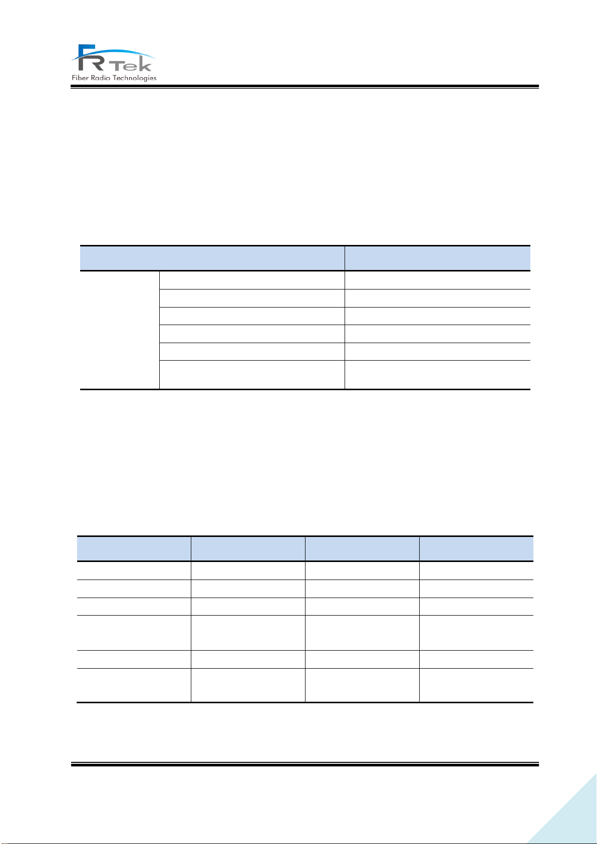
INOVA DAS is a digital optic repeater system capable of multi-band, multi-operator, and can extend
wireless service for in-building and outdoor areas. This system can accommodate up to 6 bands. It is
designed to support 700MHz (28MHz) LTE service, 850MHz (32MHz) CDMA & UMTS & LTE service,
1.9GHz (65MHz) UMTS & LTE service, 2.1GHz (70MHz) UMTS & LTE service, 2.3GHz(10MHz) LTE service,
2.5GHz(195MHz) TD-LTE service or 2.6GHz(70MHz) LTE service.
INOVA DAS MHU is configured with MWDM, MPSU, MDRU, MBIU, each unit is connected with
Harness, RF cable, and optic cable. Each component is modularized, and can be easily
mounted/dismounted, designed for simple module replacement and maintenance. Also, each unit is
designed to withstand vibration test standard (IEC 60068-2-6:2007). The EHUB and ERU is designed for
indoor use with enclosure structure designed to block dust, pollutant and insects.
PRIVATE AND CONFIDENTIAL © 2019 FRTEK CO., LTD.
Page 19
19
INOVA DAS Operating Manual
2.2 System Network Configuration
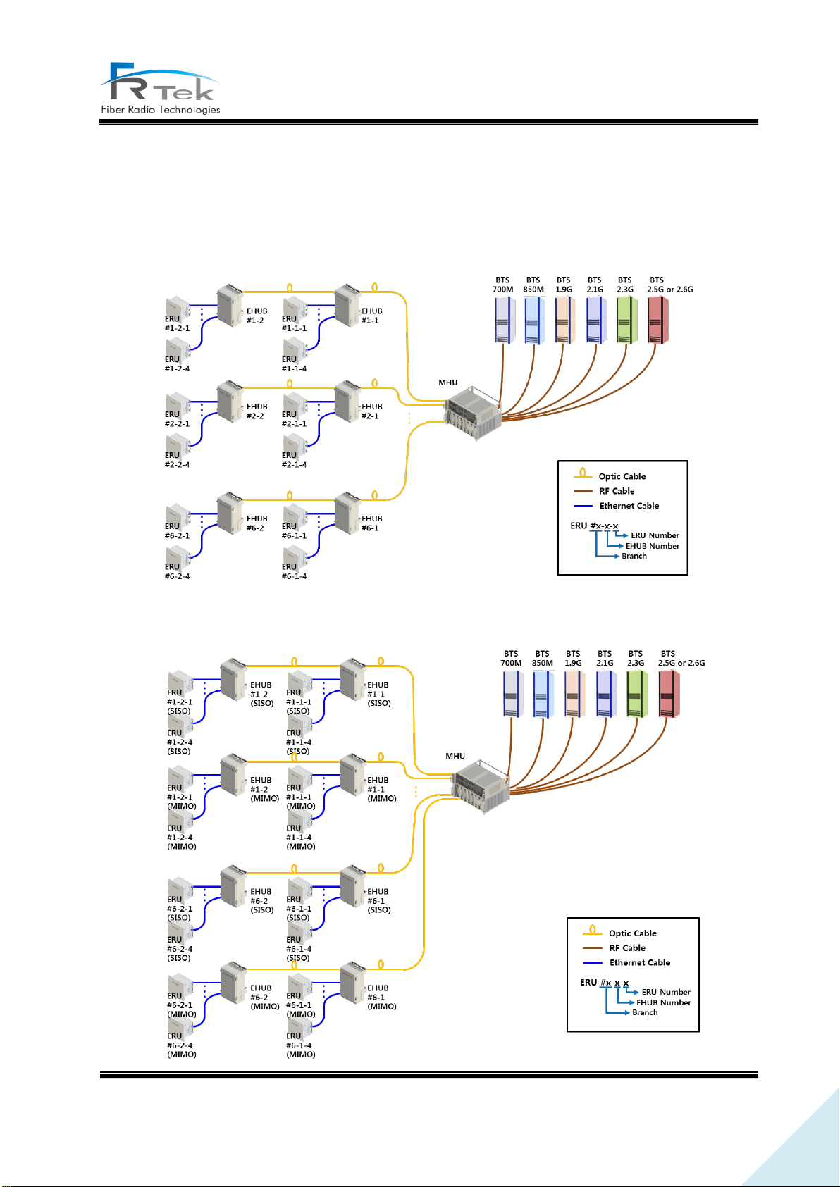
INOVA DAS basic network configuration for EHUB and ERU is as below picture.
Figure 1. Basic Network Configuration.
PRIVATE AND CONFIDENTIAL © 2019 FRTEK CO., LTD.
Page 20

20
INOVA DAS Operating Manual
Figure 2. Extended Network Configuration.
MHU is connected to the base station with wired RF cable, and connected to the lower EHUB
equipment with optic cable. EHUB is connected to ERU with wired Cat.7 cable, optic signal is converted
into Ethernet signal and transmitted to ERU or the Ethernet signal is converted into optic signal and
transmitted to MHU. Each branch of the MHU can each be connected cascade with 2 EHUBs for
operation, I EHUB can be connected to a total of 4 ERUs.
For service extension, EHUB and ERU are connected by optic cable with DTU(MHU), one branch can
operate up to 2 EHUBs, so up to 2 stages of cascade is available for configuration. Also, SISO ROU and
ROU are set to the same TX, RX Frequency.
PRIVATE AND CONFIDENTIAL © 2019 FRTEK CO., LTD.
Page 21

21
INOVA DAS Operating Manual
Chapter 3
System Configuration
3.1 ERU Figure and Configuration
PRIVATE AND CONFIDENTIAL © 2019 FRTEK CO., LTD.
Page 22
22
INOVA DAS Operating Manual
System Configuration
3.1 ERU Figure and Configuration
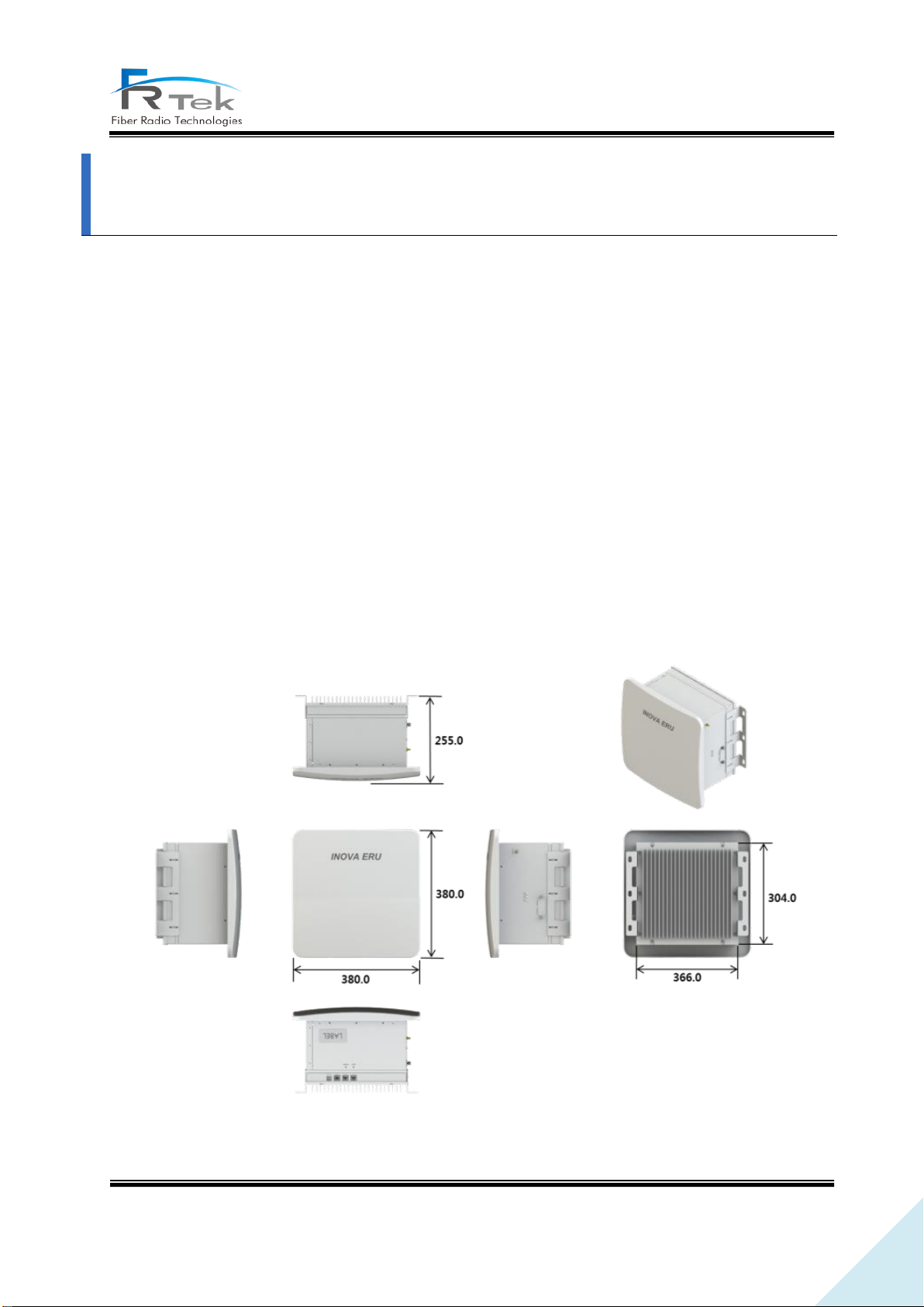
ERU is a structure that can be used in-building, enclosure is configured as ceiling fixed type. ERU is
configured with ERPSU, ERDTU, ERCPU, 4 ERFUs (ERU RF unit) and can support up to 6 frequency bands.
ERU functions can be explained as the following.
- Converts Ethernet signal to RF signal, amplifies and services through antenna. (Downlink)
- Converts RF signal to Ethernet signal, transmits to upper equipment. (Uplink)
- 700MHz, 850MHz, 1.9GHz, 2.1GHz, 2.3GHz, 2.5GHz or 2.6GHz service support.
- Receives power supply from EHUB through Cat.7 cable. (No separate PSU)
- Delay control function through Time Advance function.
- 1Gbps Ethernet port implementation for various use.
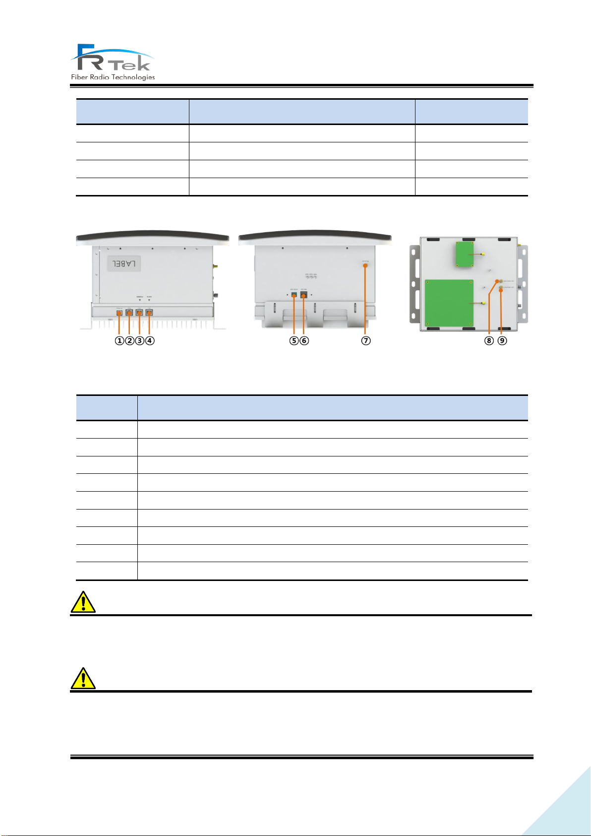
Below picture shows the ERU figure.
Figure 3. ERU Configuration
PRIVATE AND CONFIDENTIAL © 2019 FRTEK CO., LTD.
Page 23
23
INOVA DAS Operating Manual
Item
Content
Remark
Size
380 * 380 * 255 (W * H * D)
Including bracket
Weight
Approx. 19kg
Input power
PoE++
No separate PSU
Environment
In-building type
No
Content
①
ERU DTU Debug port
②
1Gbps service port
③
PoE++ Ethernet port (Power)
④
PoE++ Ethernet port (Data)
⑤
ERU CPU Debug port
⑥
Web GUI Ethernet port
⑦
Bluetooth antenna port
⑧
High Band antenna connection port
⑨
Low Band antenna connection port
Figure 4. ERU Port Configuration.
Caution
Maximum output operated from the ERU differs by frequency band, and must refer to the system
specification for operation.
Caution
Low band antenna must be accurately connected to Low band port, High band antenna must be
accurately connected to High band port.
PRIVATE AND CONFIDENTIAL © 2019 FRTEK CO., LTD.
Page 24

24
INOVA DAS Operating Manual
Chapter 4
System Specification
4.1 System Specification
4.2 Organization Specification
4.3 Electrical Specification
4.4 Environmental Specification
PRIVATE AND CONFIDENTIAL © 2019 FRTEK CO., LTD.
Page 25
25
INOVA DAS Operating Manual
Item
Performance
requirements
Remark
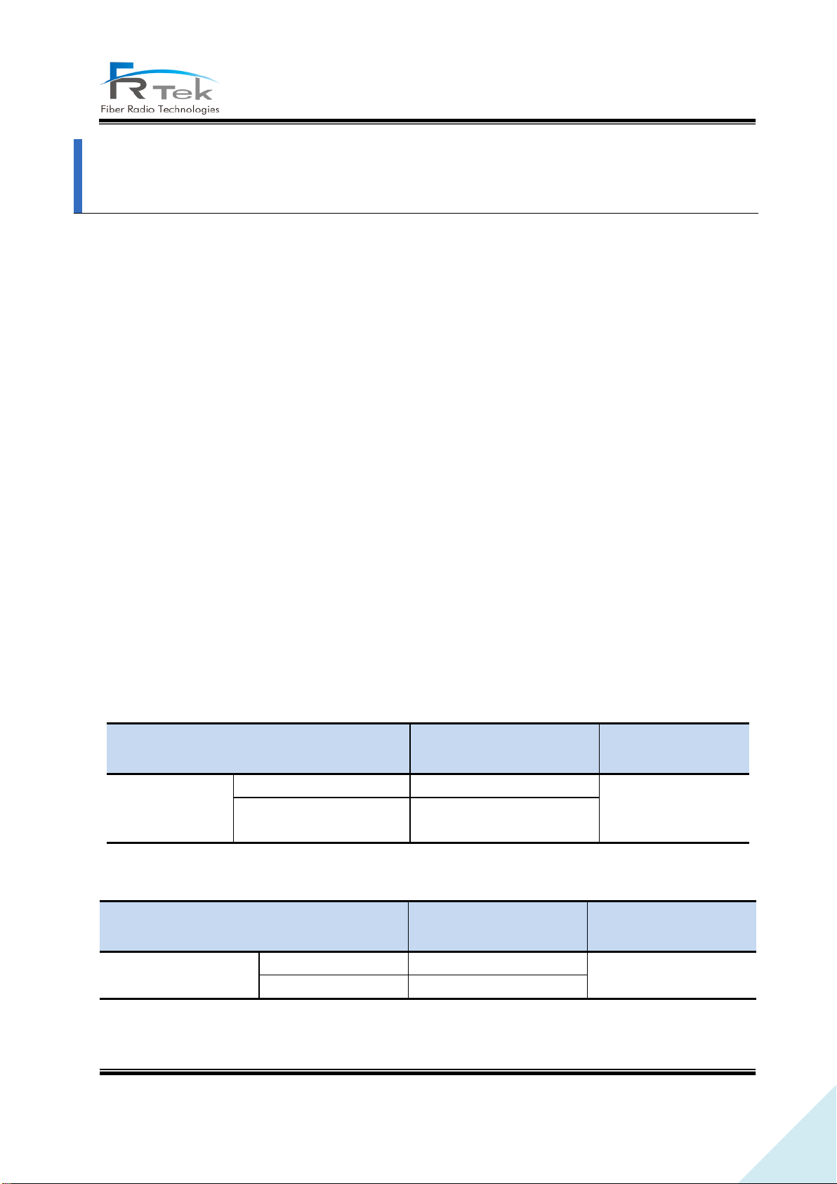
Frequency Band
Forward direction (DL)
728 ~ 756MHz
BW : 28MHz
LTE service support
Reverse direction (UL)
698 ~ 716MHz
777 ~ 787MHz
Item
Performance
requirements
Remark
Output level
Forward direction (DL)
+21dBm/Total
Tolerance : +1dB
Reverse direction (UL)
0dBm/Total
System Specification
4.1 System Specification
INOVA DAS is an US/Canada DAS equipment, supports 700MHz, 850MHz, 1.9GHz, 2.1GHz, 2.3GHz,
2.5GHz or 2.6GHz frequency bands, and all frequency bands are designed for extension. INOVA DAS
satisfies the following function and performance characteristics, and specifications not mentioned all
satisfy the functions and performance requests of “3GPP TS25.104”, “3GPP TS25.106”, “3GPP TS 36.104”.
INOVA DAS has the basic functions of the following.
- MHU is connected with base station by RF(wire) access, and connected to EHUB with one optic
cable. Also, EHUB is connected with ERU with Cat.7 cable, and ERU is installed in shaded area to
eliminate radio shaded areas.
-ERU receives power from EHUB through PoE++, and does not need a separate input power.
- Wireless quality of CDMA, UMTS, LTE, TD-LTE service is equal as base station wireless quality.
- When moving terminal enters neighboring base station, this system supports continuous handover.
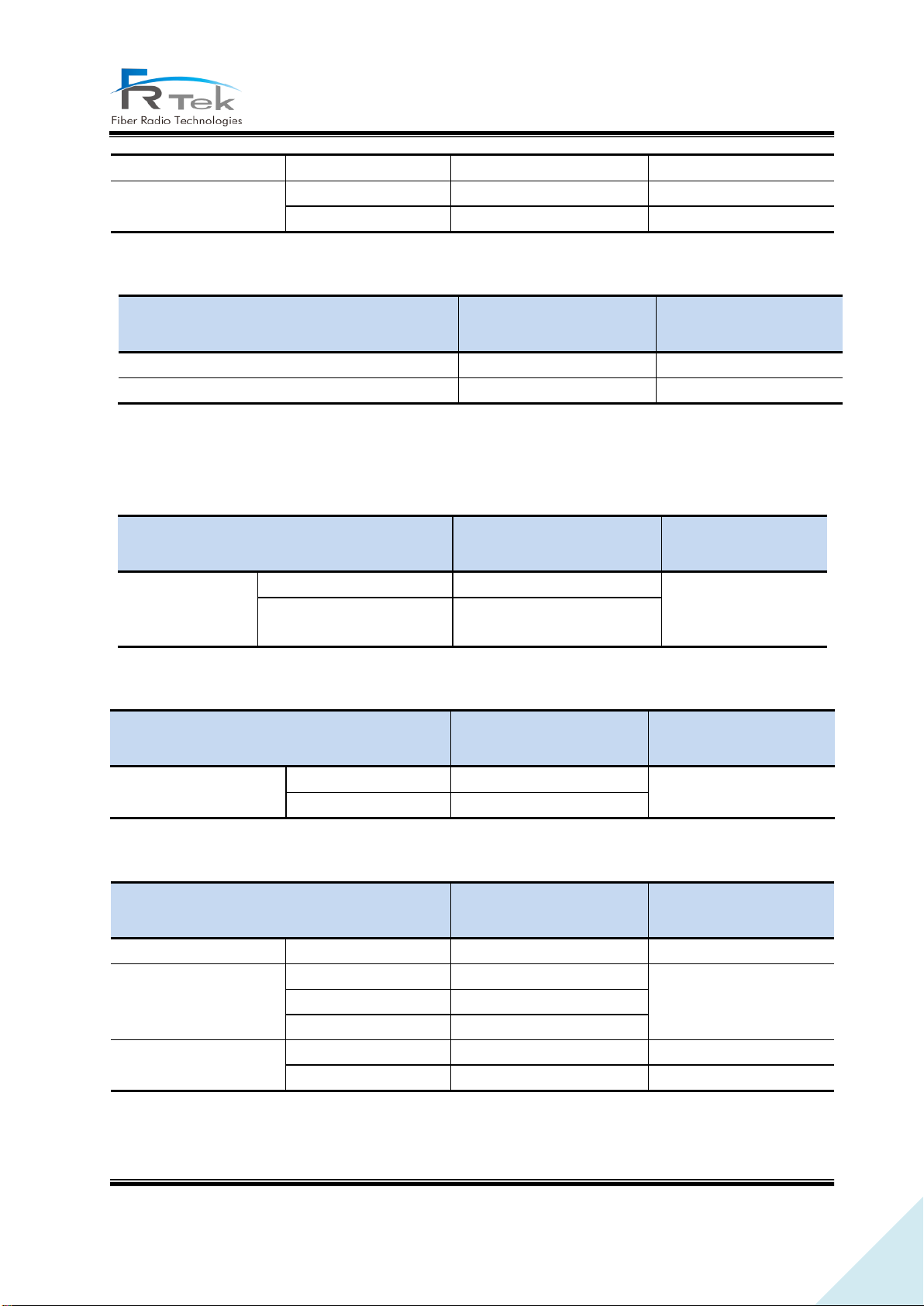
4.1.1 System Specification per Frequency Band – 700MHz
• Frequency characteristics
• Input/output characteristics
• Noise figure and spurious emission characteristics
PRIVATE AND CONFIDENTIAL © 2019 FRTEK CO., LTD.
Page 26
26
INOVA DAS Operating Manual
Item
Performance
requirements
Remark
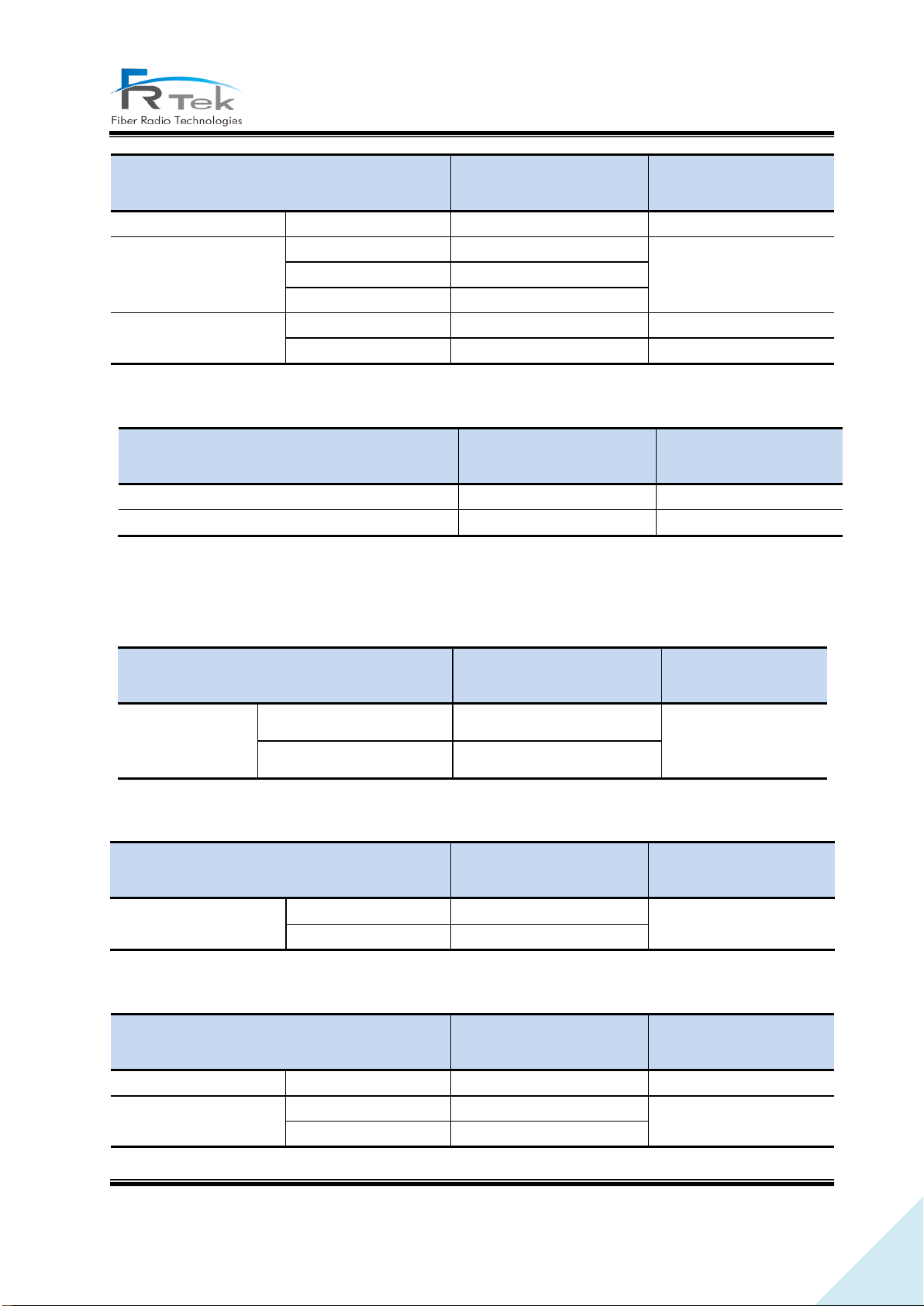
System noise figure (NF)
Reverse direction (UL)
Below 7dB
Maximum gain
Spurious emission
(within band)
±5.05MHz
Below -14dBm
Maximum output
RBW 100KHz
±10.05MHz
Below -14dBm
±15.5MHz
Below -16dBm
ACLR
BW
channel
45dBc
2 * BW
channel
45dBc
Item
Performance
requirements
Remark
VSWR
Below 1.5 : 1
Transmit/receive separation
Over 100dBc
Item
Performance
requirements
Remark
Frequency Band
Forward direction (DL)
862 ~ 894MHz
BW : 32MHz
CDMA, UMTS, LTE
service support
Reverse direction (UL)
817 ~ 849MHz
Item
Performance
requirements
Remark
Output level
Forward direction (DL)
+21dBm/Total
Tolerance : +1dB
Reverse direction (UL)
0dBm/Total
Item
Performance
requirements
Remark
System noise figure (NF)
Reverse direction (UL)
Below 7dB
Maximum gain
Spurious emission
(within band)
±5.05MHz
Below -14dBm
Maximum output
RBW 100KHz
±10.05MHz
Below -14dBm
• Other performance requirements
4.1.2 System Specification per Frequency Band – 850MHz
• Frequency characteristics
• Output characteristics
• Noise figure and spurious emission characteristics
PRIVATE AND CONFIDENTIAL © 2019 FRTEK CO., LTD.
Page 27
27
INOVA DAS Operating Manual
±15.5MHz
Below -16dBm
ACLR
BW
channel
45dBc
2 * BW
channel
45dBc
Item
Performance
requirements
Remark
VSWR
Below 1.5 : 1
Transmit/receive separation
Over 100dBc
Item
Performance
requirements
Remark
Frequency Band
Forward direction (DL)
1930 ~ 1995MHz
BW : 65MHz
UMTS, LTE service
support
Reverse direction (UL)
1850 ~ 1915MHz
Item
Performance
requirements
Remark
Output level
Forward direction (DL)
+24dBm/Total
Tolerance : +1dB
Reverse direction (UL)
0dBm/Total
Item
Performance
requirements
Remark
System noise figure (NF)
Reverse direction (UL)
Below 7dB
Maximum gain
Spurious emission
(within band)
±5.05MHz
Below -14dBm
Maximum output
RBW 100KHz
±10.05MHz
Below -14dBm
±15.5MHz
Below -16dBm
ACLR
BW
channel
45dBc
2 * BW
channel
45dBc
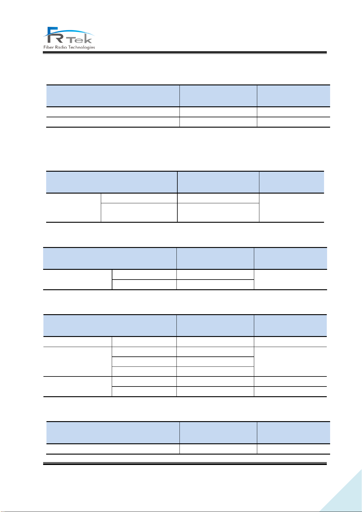
• Other performance requirements
4.1.3 System Specification per Frequency Band – 1.9GHz
• Frequency characteristics
• Output characteristics
• Noise figure and spurious emission characteristics
PRIVATE AND CONFIDENTIAL © 2019 FRTEK CO., LTD.
Page 28
28
INOVA DAS Operating Manual
Item
Performance
requirements
Remark
VSWR
Below 1.5 : 1
Transmit/receive separation
Over 100dBc
Item
Performance
requirements
Remark
Frequency Band
Forward direction (DL)
2110 ~ 2180MHz
BW : 70MHz
UMTS, LTE service
support
Reverse direction (UL)
1710 ~ 1780MHz
Item
Performance
requirements
Remark
Output level
Forward direction (DL)
+24dBm/Total
Tolerance : +1dB
Reverse direction (UL)
0dBm/Total
Item
Performance
requirements
Remark
System noise figure (NF)
Reverse direction (UL)
Below 7dB
Maximum gain
Spurious emission
(within band)
±5.05MHz
Below -14dBm
Maximum output
RBW 100KHz
±10.05MHz
Below -14dBm
±15.5MHz
Below -16dBm
ACLR
BW
channel
45dBc
2 * BW
channel
45dBc
Item
Performance
requirements
Remark
VSWR
Below 1.5 : 1
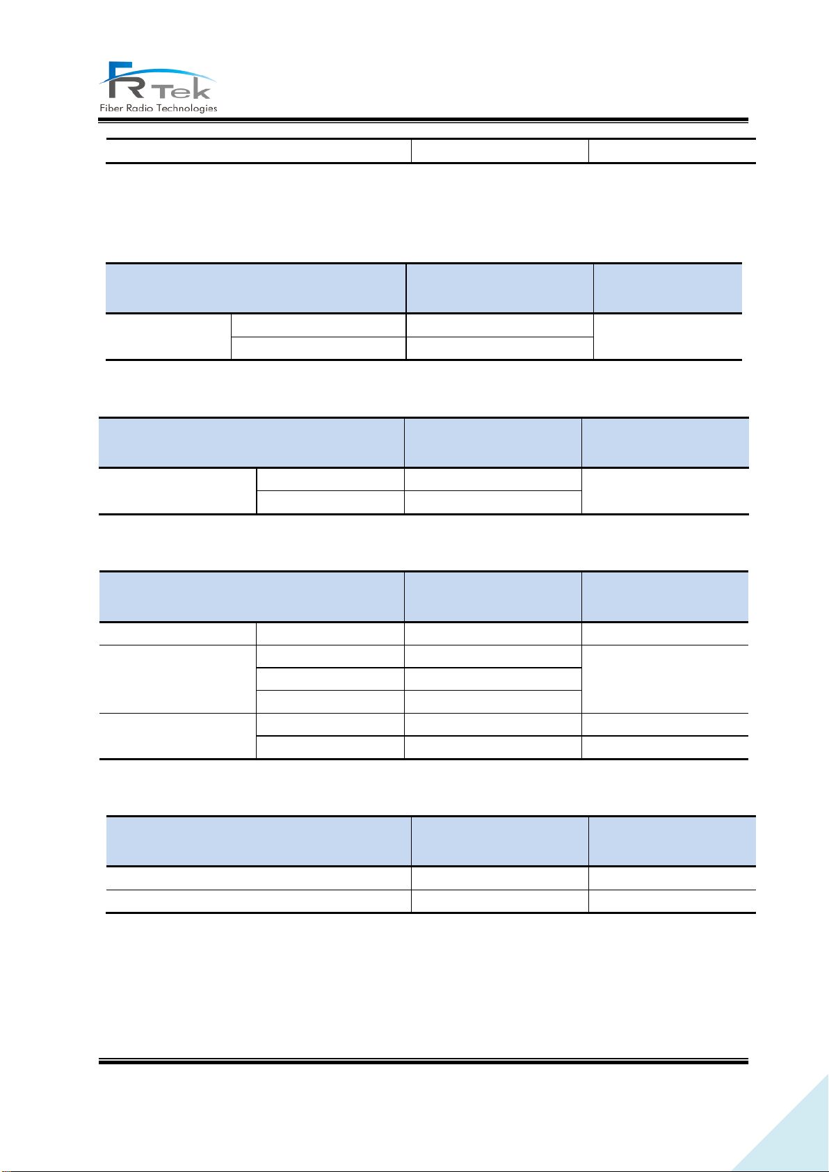
• Other performance requirements
4.1.4 System Specification per Frequency Band – 2.1GHz
• Frequency characteristics
• Output characteristics
• Noise figure and spurious emission characteristics
• Other performance requirements
PRIVATE AND CONFIDENTIAL © 2019 FRTEK CO., LTD.
Page 29
29
INOVA DAS Operating Manual
Transmit/receive separation
Over 100dBc
Item
Performance
requirements
Remark
Frequency Band
Forward direction (DL)
2350 ~ 2360MHz
BW : 10MHz
LTE service support
Reverse direction (UL)
2305 ~ 2315MHz
Item
Performance
requirements
Remark
Output level
Forward direction (DL)
Tolerance : +1dB
Reverse direction (UL)
0dBm/Total
Item
Performance
requirements
Remark
System noise figure (NF)
Reverse direction (UL)
Below 7dB
Maximum gain
Spurious emission
(within band)
±5.05MHz
Below -14dBm
Maximum output
RBW 100KHz
±10.05MHz
Below -14dBm
±15.5MHz
Below -16dBm
ACLR
BW
channel
45dBc
2 * BW
channel
45dBc
Item
Performance
requirements
Remark
VSWR
Below 1.5 : 1
Transmit/receive separation
Over 100dBc
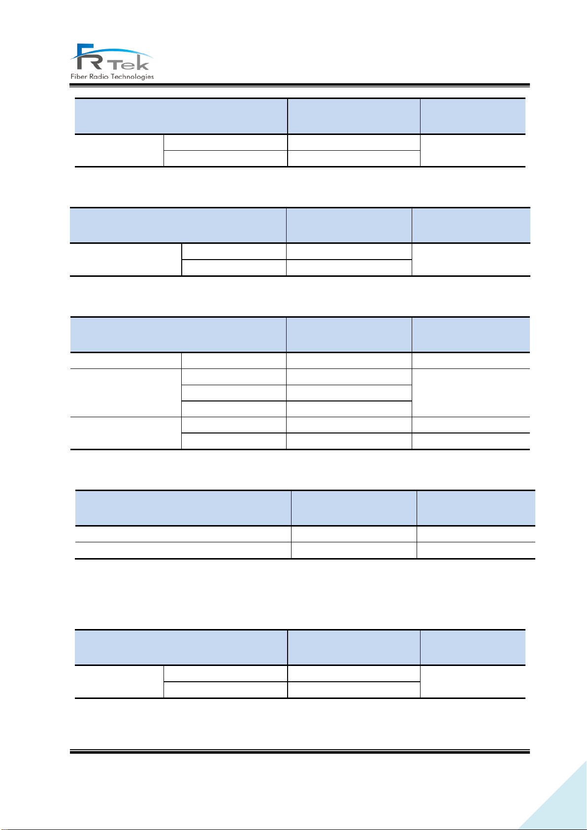
4.1.5 System Specification per Frequency Band – 2.3GHz
• Frequency characteristics
• Output characteristics
• Noise figure and spurious emission characteristics
• Other performance requirements
+21dBm/Total
4.1.6 System Specification per Frequency Band – 2.5GHz
• Frequency characteristics
PRIVATE AND CONFIDENTIAL © 2019 FRTEK CO., LTD.
Page 30
30
INOVA DAS Operating Manual
Item
Performance
requirements
Remark
Frequency Band
Forward direction (DL)
2496 ~ 2690MHz
BW : 194MHz
TD-LTE service support
Reverse direction (UL)
2496 ~ 2690MHz
Item
Performance
requirements
Remark
Output level
Forward direction (DL)
+24dBm/Total
Tolerance : +1dB
Reverse direction (UL)
0dBm/Total
Item
Performance
requirements
Remark
System noise figure (NF)
Reverse direction (UL)
Below 7dB
Maximum gain
Spurious emission
(within band)
±5.05MHz
Below -14dBm
Maximum output
RBW 100KHz
±10.05MHz
Below -14dBm
±15.5MHz
Below -16dBm
ACLR
BW
channel
45dBc
2 * BW
channel
45dBc
Item
Performance
requirements
Remark
VSWR
Below 1.5 : 1
Transmit/receive separation
Over 100dBc
Item
Performance
requirements
Remark
Frequency Band
Forward direction (DL)
2620 ~ 2690MHz
BW : 70MHz
LTE service support
Reverse direction (UL)
2500 ~ 2570MHz
• Output characteristics
• Noise figure and spurious emission characteristics
• Other performance requirements
4.1.7 System Specification per Frequency Band – 2.6GHz
• Frequency characteristics
• Output characteristics
PRIVATE AND CONFIDENTIAL © 2019 FRTEK CO., LTD.
Page 31
31
INOVA DAS Operating Manual
Item
Performance
requirements
Remark
Output level
Forward direction (DL)
+24dBm/Total
Tolerance : +1dB
Reverse direction (UL)
0dBm/Total
Item
Performance
requirements
Remark
System noise figure (NF)
Reverse direction (UL)
Below 7dB
Maximum gain
Spurious emission
(within band)
±5.05MHz
Below -14dBm
Maximum output
RBW 100KHz
±10.05MHz
Below -14dBm
±15.5MHz
Below -16dBm
ACLR
BW
channel
45dBc
2 * BW
channel
45dBc
Item
Performance
requirements
Remark
VSWR
Below 1.5 : 1
Transmit/receive separation
Over 100dBc
Item
Type
Option
MHU
19”Rack type
In-building type
EHUB
Wall fixed type
In-building type
ERU
Wall/ceiling fixed type
In-building type
• Noise figure and spurious emission characteristics
• Other performance requirements
4.2 Organization Specification
4.2.1 Structure and Type
• MHU, EHUB, ERU of INOVA DAS should be designed considering installation space and operator's
convenience, and the structure design should be elegant.
• Components of INOVA DAS should be modular, installation should be made in a structure that
each component can be easily mounted and dismounted, and should be easy to replace and
maintain.
PRIVATE AND CONFIDENTIAL © 2019 FRTEK CO., LTD.
Page 32

32
INOVA DAS Operating Manual
• Each equipment of INOVA DAS is designed in a structure to block dust, pollutant and insects.
• Each equipment of INOVA DAS is designed to withstand vibration test standard.
• All parts of the cabinet should be smoothly treated in order to prevent personal physical injury
during maintenance.
• INOVA DAS provides Timing Advance function for network optimization.
4.2.2 Manufacturing and Processing
• Sealing materials have a very strong thermal properties, and are not torn or damaged by chemicals.
• Internal/external wiring of INOVA DAS is designed elegantly with lapping method or connecter
connecting method, and can withstand vibration.
• Printed circuit board of INOVA DAS is made of glass epoxy resin or equivalent products, soldering
area is exquisite, appearance after soldering is elegant, and has electricity insulator film in order to
prevent reduction of insulation resistance due to corrosion, pollutant, and accumulation of dust and
moisture.
• Internal/external surface of painted cabinet has the same color, cabinet exterior is designed to
withstand blistering, peeling and cracking for 5 years.
• INOVA DAS is designed and manufactured considering methods for emission carbon reduction.
(power consumption reduction, material reduction, etc)
4.2.3 Materials and Components
• Passive devices used in INOVA DAS have stable characteristics on frequency and temperature
change, active devices are industrial or equivalent semiconductors, and integrated circuits are solid-
state devices.
• Wires used in INOVA DAS are tolerance coated wiring with sufficient current capacity and withstands
voltage.
• Coaxial line used to connect each component of INOVA DAS are shielded cable of aluminum or
copper cladding.
• All metal used in INOVA DAS are designed to withstand not only the generally known corrosion,
but also local corrosion including stress corrosion and cracking.
• Plastic used should be insoluble to solvent, and is designed to be free from cracking, molting, and
color change when exposed to ammonia.
PRIVATE AND CONFIDENTIAL © 2019 FRTEK CO., LTD.
Page 33

33
INOVA DAS Operating Manual
• Plastic is designed not to crack when exposed to materials(ex-insulators, filing compound) used for
cable manufacturing.
• Enclosure, components, PCB, solder, cables of INOVA follow RoHS(Restriction to hazardous
substances).
4.3 Electrical Specification
• Power supplied to MHU, EHUB operates normally on commercial power supply (AC120/60Hz).
• There is overvoltage and over current protection function for the power supply.
• When after momentary power outage occurs, RF set value automatically returns to the status right
before the power outage.
• Withstand voltage of primary side power terminal and enclosure ground on input/output terminal
is DC 2.75KV for one minute, and leakage current is within 100mA.
• Withstand voltage of primary side power terminal and secondary side ground on input/output
terminal is DC 4.25KV for one minute, and leakage current is within 100mA.
• Leakage current on phase(120V) is within 3.5mA.
• Surge should not be abnormal when more than 2KV voltage is applied on AC input terminal.
• Equipment grounding is located on both sides of the enclosure.
• Fuse should be visually confirmable(MHU, EHUB), and should be replaceable without equipment
disassemble.
• All components used on INOVA DAS satisfies EMI terms of FCC title 47, part 15, subject J, class A.
• Grounding strap to ground the grounding wire of #6AWG must be attached to the enclosure.
4.4 Environmental Specification
• No condensation marks should occur inside the equipment when specified temperature and
humidity tests are performed.
• INOVA DAS should be designed to have no internal condensation or deterioration due to humidity
and internal, external temperature differences, even when it is not normally operated.
• When performing specified vibration test, system performance or mechanical damage should not
occur.
• When performing specified waterproof test, there should be no moisture penetration inside the
equipment.
• MHU environment test should be performed in accordance to ambient temperature operation
PRIVATE AND CONFIDENTIAL © 2019 FRTEK CO., LTD.
Page 34
34
INOVA DAS Operating Manual
Item
Conditions
Performance Requirements
Environment
test
In-building
- Temperature : -10 ~ +45C
- Humidity : 0 ~ 90% RH
- Output change : within ±3dB
- No problem inside/outside
enclosure
Vibration test
- 10 ~ 150Hz, gravitational
acceleration 1G
(IEC 60068-2-6)
- No system performance change
- No problem inside/outside
enclosure
Noise test
- GR-65-Core(4.6), Level 2
- Below 65dBA (When using
external Fan)
standards(in-building standard, for external enclosure outdoor standard).
• Environment test items and method repetition cycle item should be in accordance to operator
environment test procedure.
Main environment test conditions for INOVA DAS are as the following.
PRIVATE AND CONFIDENTIAL © 2019 FRTEK CO., LTD.
Page 35

35
INOVA DAS Operating Manual
Chapter 5
System Installation
5.1 Tools
5.2 ERU Installation
5.3 2.5GHz, 2.6GHz Setting Method
PRIVATE AND CONFIDENTIAL © 2019 FRTEK CO., LTD.
Page 36
36
INOVA DAS Operating Manual
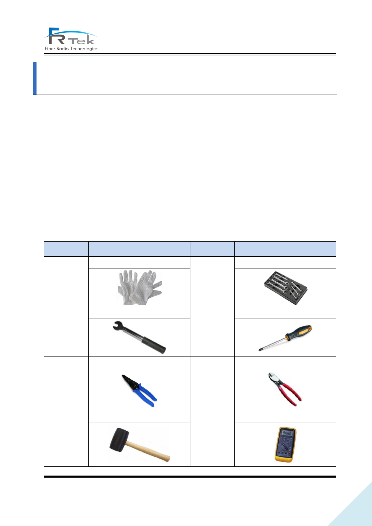
No.
Tools
No.
Tools
1
ESD Gloves
2
Torque Wrench Set
3
33mm Torque Wrench
4
+, 3Φ Screw Driver
5
Wire Stripper
6
Wire Cutter
7
Rubber Mallet
8
Digital Multi-meter
System Installation
“This manual is to provide product installation method and product information to the user operating
the INOVA DAS system, the repeater manager who uses the operation manual needs to require
professional knowledge and experience on construction operation of repeater systems. “
This chapter explains how to connect power cables and how to install each equipment and optic
cable. It specifically describes MHU(MWDM, MPSU, MDRU, MBIU), EHUB, ERU installation method and
cable connecting method.
5.1 Tools
Tools needed for installation are as below.
PRIVATE AND CONFIDENTIAL © 2019 FRTEK CO., LTD.
Page 37
37
INOVA DAS Operating Manual
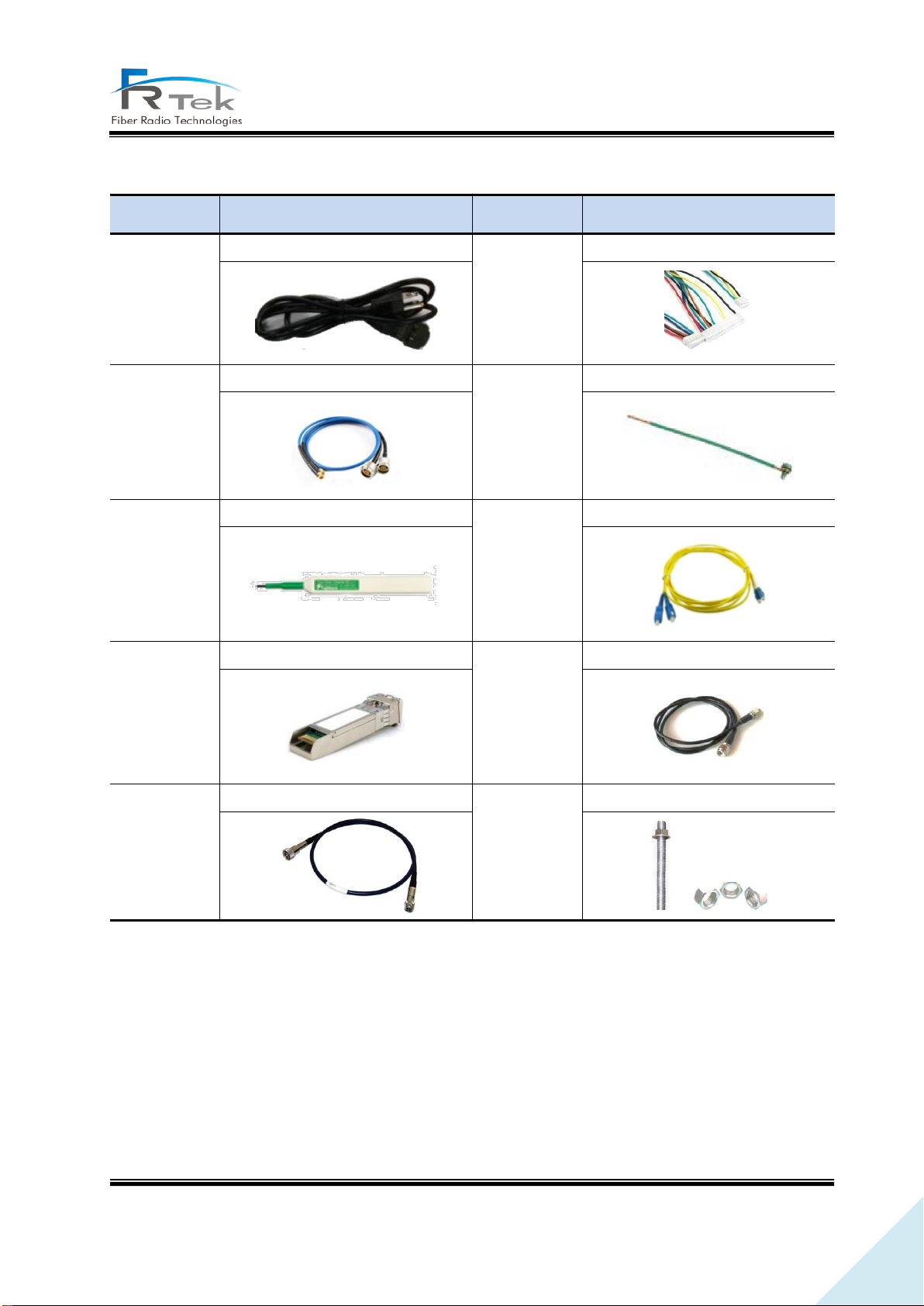
No.
Tools
No.
Tools
1
AC Cable
2
INOVA Harness Cable
3
INOVA RF Cable
4
Ground Wire Line
5
Optic Connector Cleaner
6
LC-type Optic Fiber
7
Optic Module
8
SMA Cable
9
ANT RF Cable
10
Bracket Bolt/Nut
Other cables and components needed for installation are as below.
PRIVATE AND CONFIDENTIAL © 2019 FRTEK CO., LTD.
Page 38
38
INOVA DAS Operating Manual
5.2 ERU Installation
5.2.1 Product Ceiling Installation
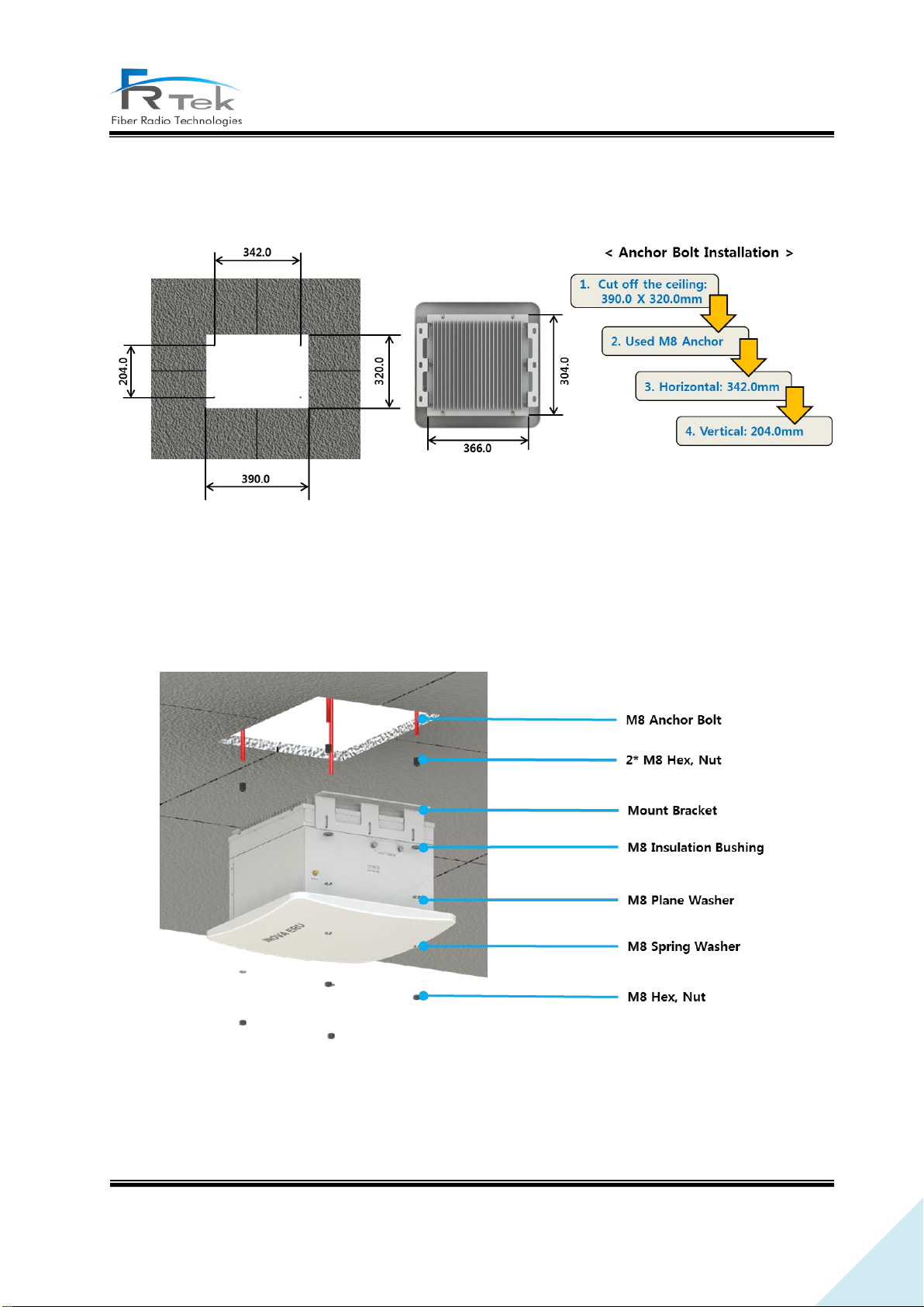
Figure 5. ERU Ceiling Installation.
ERU can be installed on the ceiling through mount bracket. Above figure is a simplified drawing of
the ceiling. Use anchor bolt to fix ERU for ceiling installation.
Above figure is the assemble drawing of EHUB ceiling installation. The assemble orders are as below.
1. Insert bakelite to M8 Anchor Bolt, and locate ERU according to M8 Anchor Bolt location.
Figure 6. ERU Ceiling Installation Assemble.
PRIVATE AND CONFIDENTIAL © 2019 FRTEK CO., LTD.
Page 39
39
INOVA DAS Operating Manual
2. Insert M8 Insulation Bushing, M8 Plane Washer, and M8 Spring Washer.
3. Tighten M8 Hex, Nut using spanner.
5.2.2 Product Wall Installation
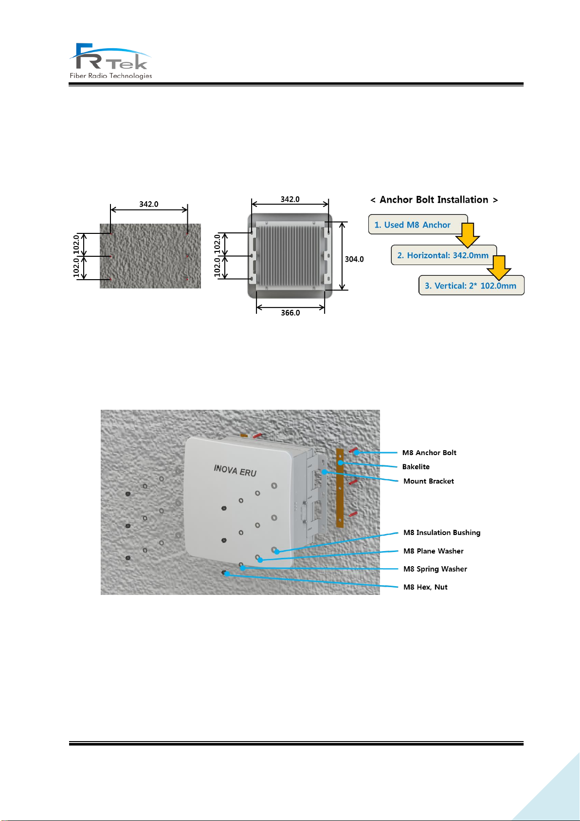
Figure 7. ERU Anchor Bolt Wall Assemble.
ERU can be installed on the wall through mount bracket. Above figure is a simplified drawing of the
wall. Us anchor bolt to fix ERU for wall installation.
Figure 8. ERU Wall Installation Assemble.
Above figure is the assemble drawing of ERU wall installation. The assemble orders are as below.
1. Insert bakelite to M8 Anchor Bolt, and locate ERU according to M8 Anchor Bolt location.
2. Insert M8 Insulation Bushing, M8 Plane Washer, and M8 Spring Washer.
3. Tighten M8 Hex, Nut using spanner.
PRIVATE AND CONFIDENTIAL © 2019 FRTEK CO., LTD.
Page 40
40
INOVA DAS Operating Manual
5.2.3 Antenna Connection
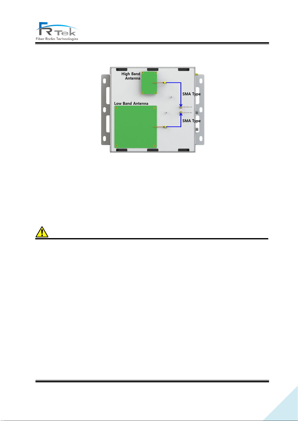
Figure 9. ERU Antenna Connection.
ERU is installed on shaded area to support continuous telecommunication service. Below the ERU
antenna cover there are 2 antennas (Low band, High band) and each antenna port as above figure. The
low band antenna should be connected to the low band antenna port, and the high band antenna
should be connected to the high band antenna port.
Reference
ERU low band antenna gain is 00dB, high band antenna gain is 00dB.
5.3 2.5GHz, 2.6GHz Setting Method
INOVA DAS is basically available to service 700MHz, 850MHz, 1.9GHz, 2.1GHz, 2.3GHz frequency
bands, and is designed to select one of 2.5GHz or 2.6GHz frequency band for service. So according to
the module inserted on the MHU and ERU, it can service 700MHz, 850MHz, 1.9GHz, 2.1GHz, 2.3GHz,
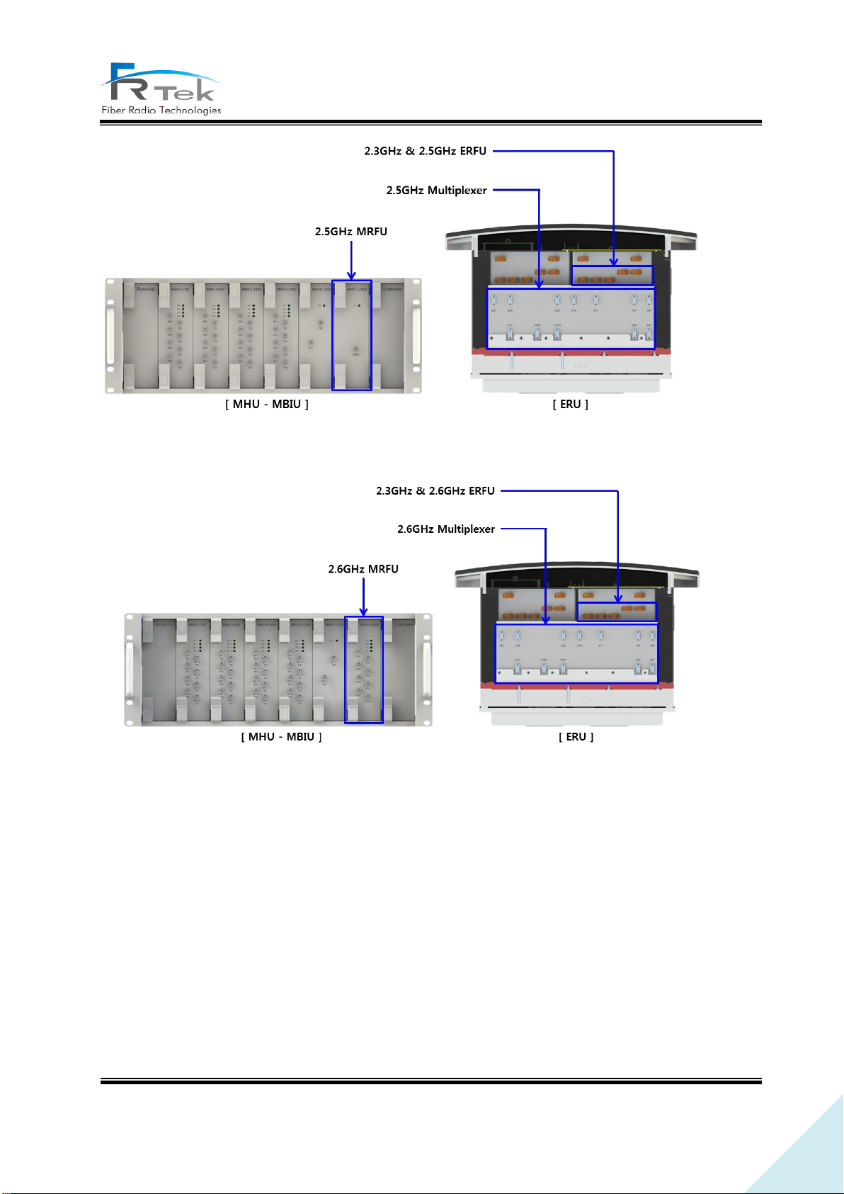
2.5GHz or 700MHz, 850MHz, 1.9GHz, 2.1GHz, 2.3GHz, 2.6GHz. Therefore, as the below figure for 2.5Ghz
and 2.6Ghz, the MRFU, ERFU, ERU Multiplexer of the desired frequency band should be inserted in the
INOVA DAS for service.
PRIVATE AND CONFIDENTIAL © 2019 FRTEK CO., LTD.
Page 41
41
INOVA DAS Operating Manual
Figure 10. For 2.5GHz Service, Insert 2.5GHz MRFU/ERFU/Multiplexer Module.
Figure 11. For 2.6GHz Service, Insert 2.6GHz MRFU/ERFU/Multiplexer Module.
PRIVATE AND CONFIDENTIAL © 2019 FRTEK CO., LTD.
Page 42

42
INOVA DAS Operating Manual
Chapter 6
Local GUI(Graphical User Interface)
6.1 Local GUI Main Screen
6.2 Local GUI ERU Screen
PRIVATE AND CONFIDENTIAL © 2019 FRTEK CO., LTD.
Page 43
43
INOVA DAS Operating Manual
Local GUI(Graphical User Interface)
“This manual is to provide product installation method and product information to the user operating
the INOVA DAS system, the repeater manager who uses the operation manual needs to require
professional knowledge and experience on construction operation of repeater systems. “
• This operation program is designed for controlling and monitoring INOVA DAS.
• This operation program uses USB-B type port configured on each equipment CPU for
telecommunication.
• User is available to monitor and control the INOVA DAS operation status through MHU and ERU
main screen.
6.1 Local GUI Main Screen
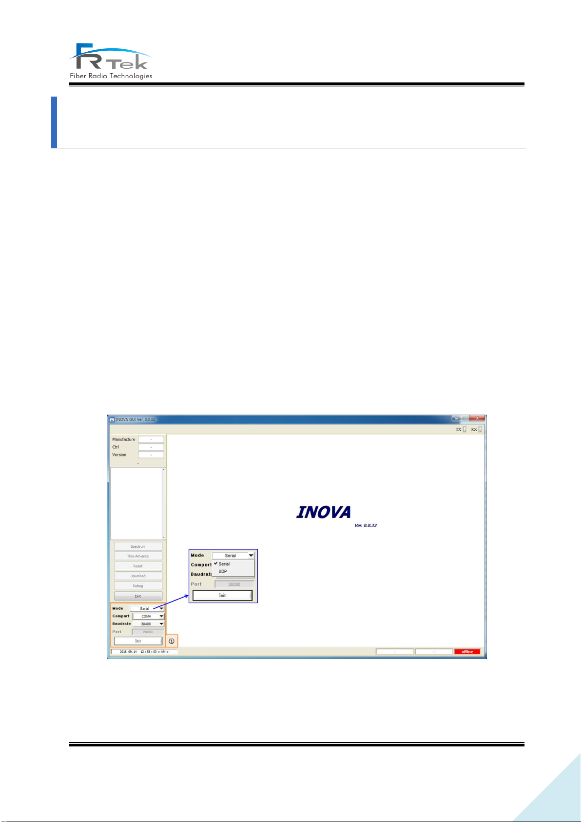
When executing Local GUI of INOVA DAS, the GUI initial screen is shown as the above figure. Local
GUI and INOVA DAS equipment can be connected with serial communication or UDP communication..
Figure 12. Local GUI Initial Screen.
PRIVATE AND CONFIDENTIAL © 2019 FRTEK CO., LTD.
Page 44
44
INOVA DAS Operating Manual
Serial telecommunication can be used by connecting to USB B-type port of MCPU or ERCPU, UDP
telecommunication can be used by connecting to Ethernet port of MCPU or ERCPU.
① Telecommunication Connection
This is the window to select telecommunication method for GUI operation with INOVA DAS.
- Mode : You can select GUI connection method for equipment. (Serial or UDP telecommunication)
- Comport : You can select auto set serial port on GUI notebook.
- Baudrate : Basically uses 38400.
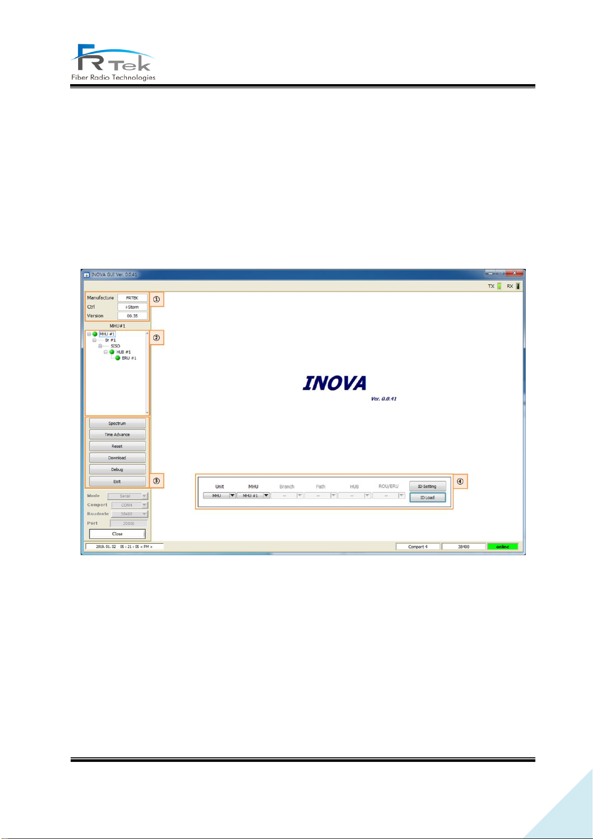
GUI screen as above figure will show up when selecting telecommunication method and connecting
GUI and INOVA DAS. When accessing to the desired equipment (MHU, EHUB, ERU) from the screen,
GUI screen of the equipment will appear.
① Manufacturer Information
Window to check INOVA DAS manufacturer information and GUI version information.
② Equipment Tree
Figure 13. Local GUI Main Screen.
PRIVATE AND CONFIDENTIAL © 2019 FRTEK CO., LTD.
Page 45
45
INOVA DAS Operating Manual
Window to check current INOVA DAS connection status all at once. From this tree configuration,
the status of equipment connected to each branch of the MHU, connected EHUB, ERU configuration
information can be checked, and existence of equipment alarm can be confirmed through the alarm
on the side. Also, by selecting the desired equipment on this window, the screen to check status
information and to control the equipment will show.
③ GUI Function
INOVA spectrum analyzer function or time advance, download function can be checked on this
item.
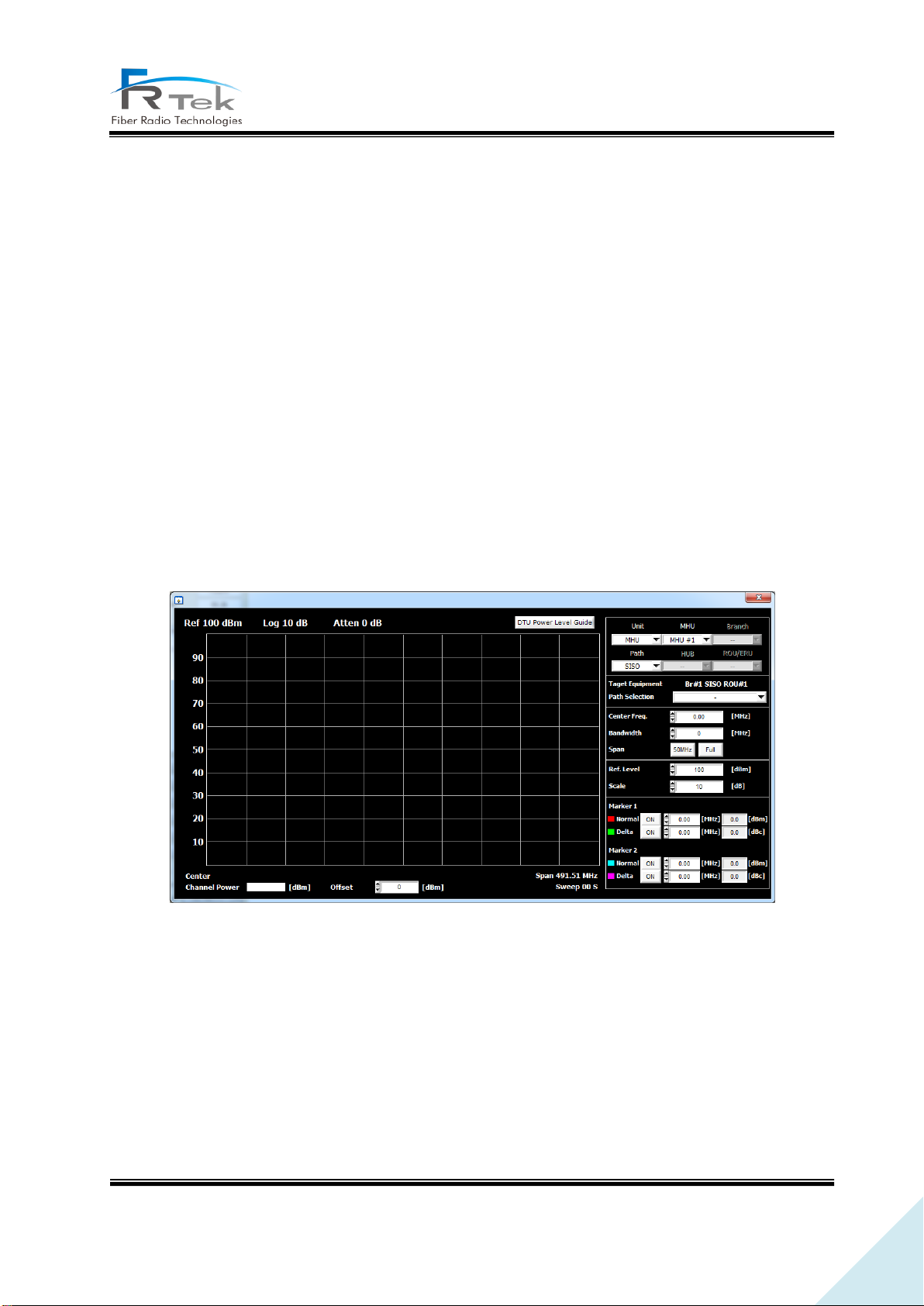
- Spectrum : Item to use INOVA DAS spectrum analyzer function. Digital input/output signal of
all frequency bands can be checked from this function, and each service signal per frequency
can be checked real time. Spectrum Analyzer screen is as below.
Figure 14. Spectrum Analyzer Window Screen.
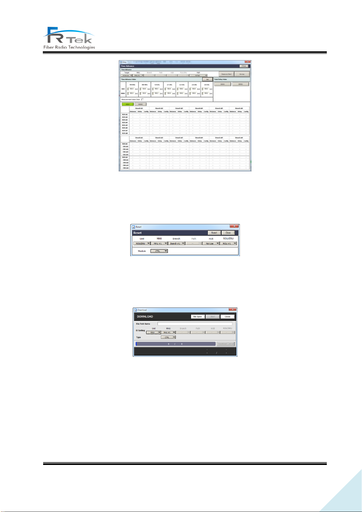
- Time Advance : Item to use INOVA DAS time advance function. Measures delay between optic
cables of configured equipment, and can automatically set system delay to user set delay value.
Time Advance screen is as below.
PRIVATE AND CONFIDENTIAL © 2019 FRTEK CO., LTD.
Page 46
46
INOVA DAS Operating Manual
Figure 15. Time Advance Window Screen.
- Reset : Item to use reset function of CPU or DTU of the current configured equipment. Below
figure shows the reset window.
Figure 16. Reset Window Screen.
- Download : Item to use function to download firmware such as CPU, DTU, RF unit of the current
configured equipment. Below figure shows the download window..
Figure 17. Download Window Screen.
- Debug : Item to use debug on GUI.
- Exit : Item to use when exiting current GUI.
④ ID Setting
Item to read set ID, and reset ID. When using this item, GUI needs to be accessed by connecting
cable to EHUB CPU and ERCPU. When ID is assigned, EHUB ID and ERU ID must all be set.
PRIVATE AND CONFIDENTIAL © 2019 FRTEK CO., LTD.
Page 47
47
INOVA DAS Operating Manual
6.2 Local GUI ERU Screen
6.2.1 ERU Main Screen
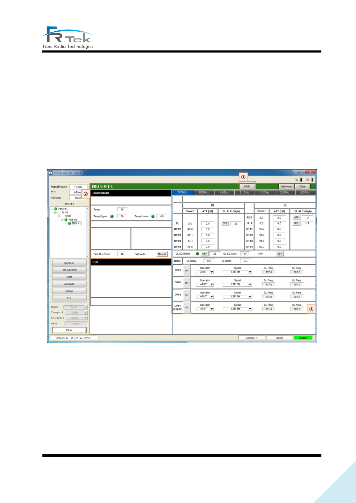
• <Status Mode> requests ERU equipment's status information at intervals of 1
• By clicking <Set Mode> button, <Set> button next to the button is activated, enters to <Set
Mode>, stops status request and can control ERU items.
• When setting is successfully completed, <Setting Success> message window is shown.
• When clicking <Close> button the window will close, and go back to <GUI Main>.
Above figure shows the INOVA ERU GUI screen. ERU main screen is available to monitor temperature,
status monitoring and control of the RF signal.
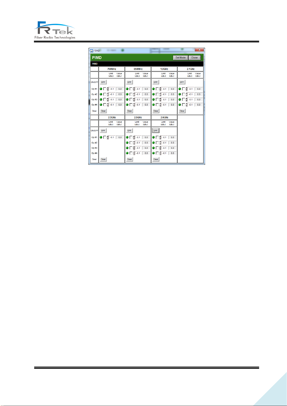
① PIMD
Item for ERU PIMD function control. On/off button to generate CW tone on RX path (Uplink) of
frequency band exists, and items to measure and check RX gain is configured.
Figure 18. Local GUI ERU Screen.
PRIVATE AND CONFIDENTIAL © 2019 FRTEK CO., LTD.
Page 48
48
INOVA DAS Operating Manual
Figure 19. ERU PIMD Screen.
② Environment
Item to check ERU temperature alarm.
③ Band Information
TX output signal(Downlink) and RX input signal (Uplink) status monitoring and control per each
frequency band is available in this item, and channel information per each frequency set on MHU
can be checked. Also, same as MHU, 2.5GHz and 2.6GHz can be activated/deactivated according to
inserted RRFU.
PRIVATE AND CONFIDENTIAL © 2019 FRTEK CO., LTD.
Page 49
49
INOVA DAS Operating Manual
6.2.2 ERU Main Screen per Frequency
• 700MHz Band Information
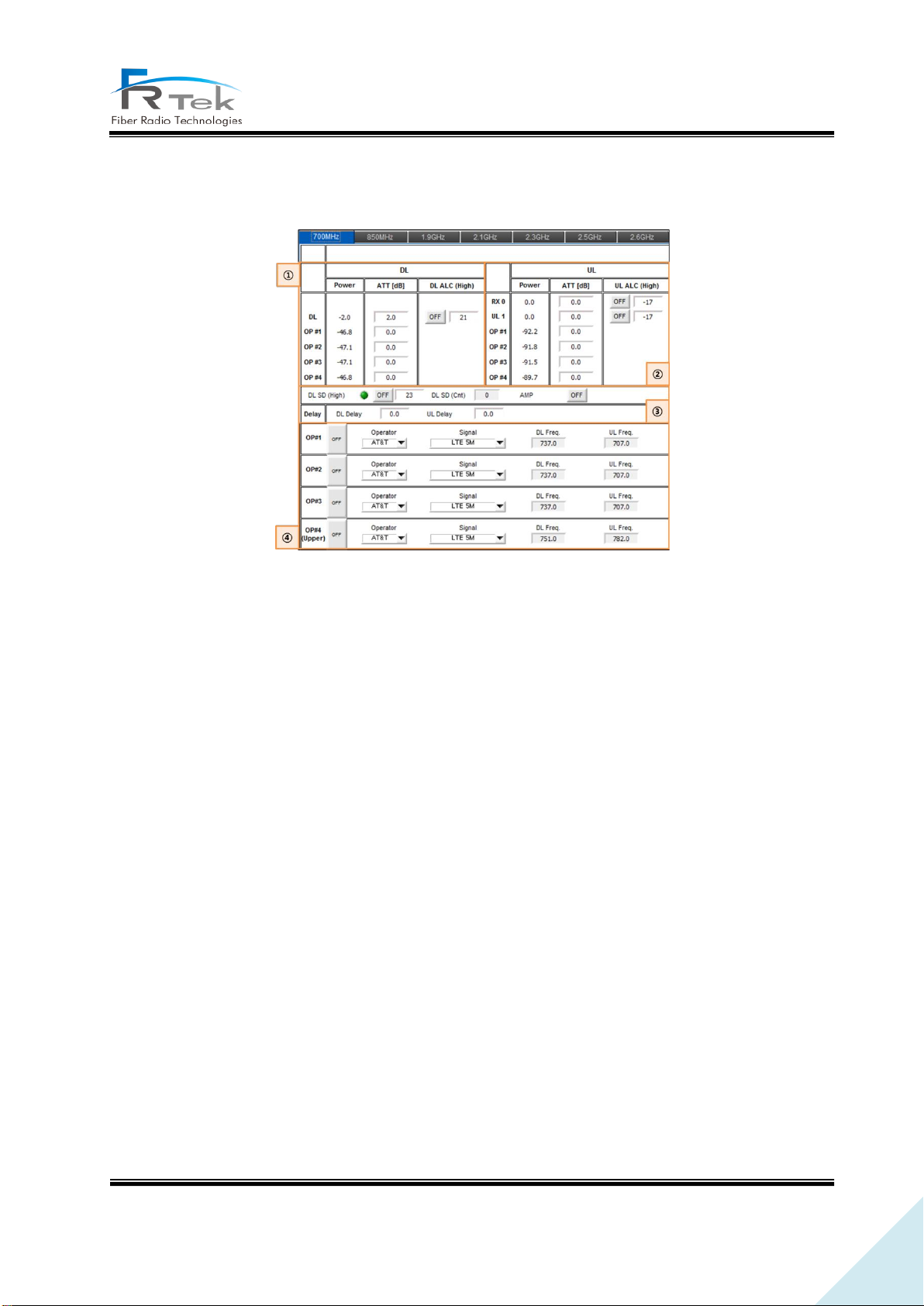
Figure 20. 700MHz ERU Band Information Screen.
① 700MHz TX Signal Monitoring and Control
The RF signal output level(Downlink) of 700MHz band received from the MHU, EHUB can be
checked on this item, and the output level can be manually adjusted by controlling ATTen. according
to the operator. Also, ALC function is configured for the user to automatically adjust output level by
inputting the desired ALC level and turning the function ON.
② 700MHz RX Signal Monitoring and Control
The RF signal input level(Uplink) of 700MHz band received from the terminal can be checked on
this item. Also, same as TX, input level can be manually adjusted by controlling ATTen., and automatic
input level adjustment through ALC is implemented.
③ 700MHz TX Shutdown and Delay Control
Item implements shutdown function of automatically turning HPA off when 700MHz TX output
signal gets high due to overpower. User can set shutdown signal level, function operates when switch
is on.
Also, item is configured with delay control item to control 700MHz system delay. When user inputs
specific value on this delay window, 700MHz system delay applies with the user input value added.
PRIVATE AND CONFIDENTIAL © 2019 FRTEK CO., LTD.
Page 50
50
INOVA DAS Operating Manual
④ 700MHz Channel Status
Item cannot be controlled on the ERU screen, the operator label, channel filter type, downlink
frequency, uplink frequency set from MHU per each operator can be checked.
• 850MHz Band Information
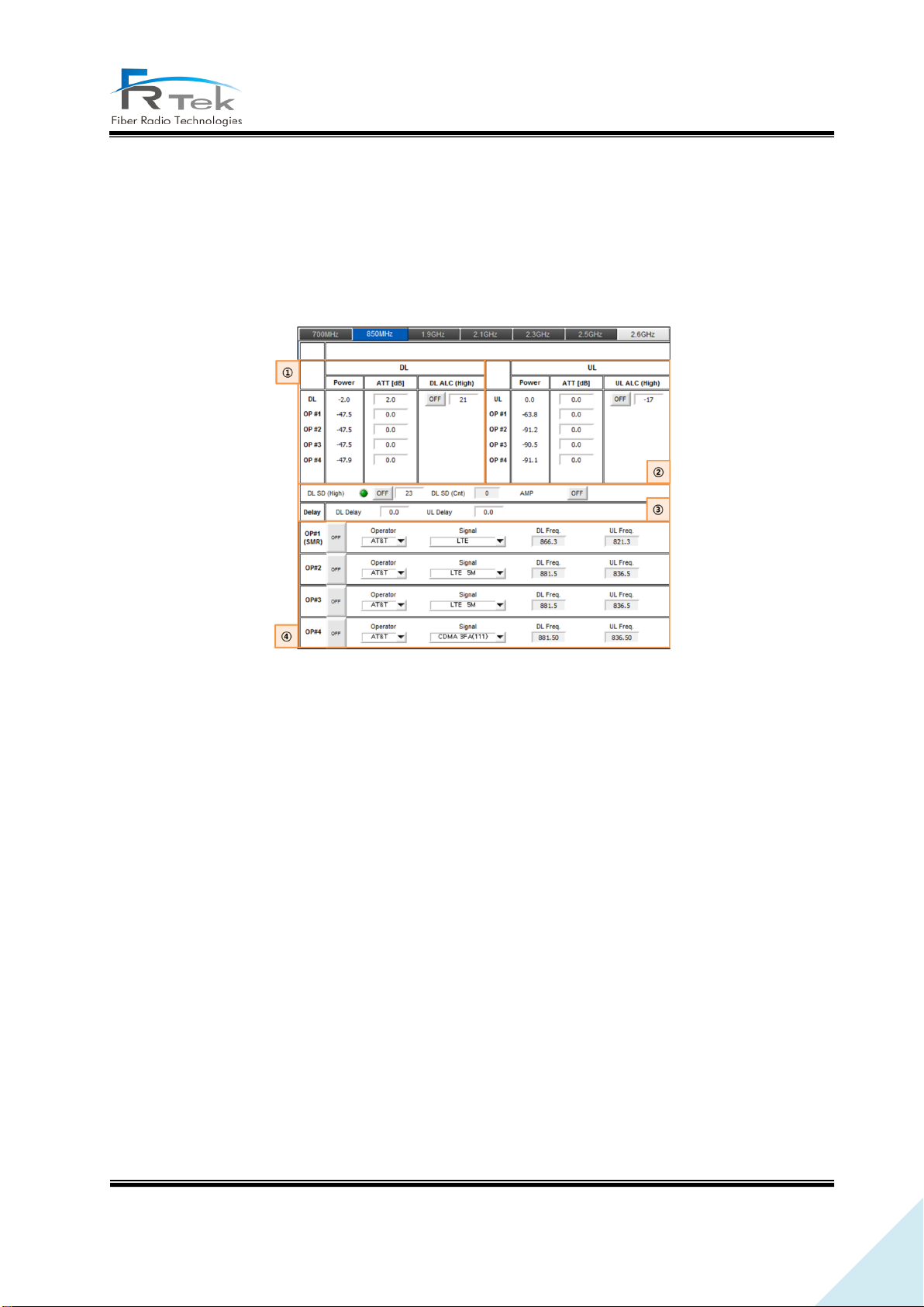
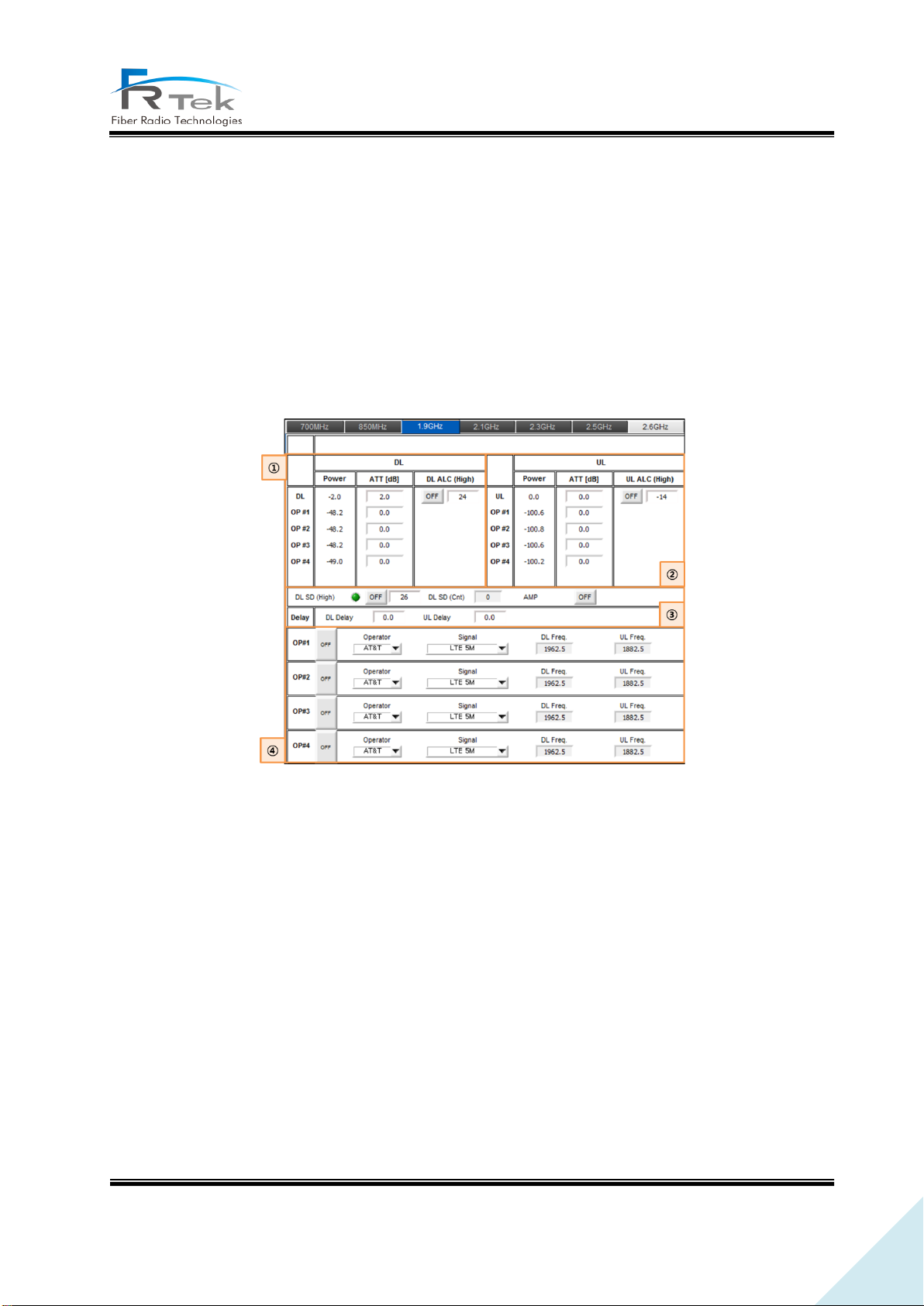
Figure 21. 850MHz ERU Band Information Screen.
① 850MHz TX Signal Monitoring and Control
The RF signal output level(Downlink) of 850MHz band received from the MHU, EHUB can be
checked on this item, and the output level can be manually adjusted by controlling ATTen. according
to the operator. Also, ALC function is configured for the user to automatically adjust output level by
inputting the desired ALC level and turning the function ON.
② 850MHz RX Signal Monitoring and Control
The RF signal input level(Uplink) of 850MHz band received from the terminal can be checked on
this item. Also, same as TX, input level can be manually adjusted by controlling ATTen., and automatic
input level adjustment through ALC is implemented.
③ 850MHz TX Shutdown and Delay Control
Item implements shutdown function of automatically turning HPA off when 850MHz TX output
signal gets high due to overpower. User can set shutdown signal level, function operates when switch
is on.
PRIVATE AND CONFIDENTIAL © 2019 FRTEK CO., LTD.
Page 51
51
INOVA DAS Operating Manual
Also, item is configured with delay control item to control 850MHz system delay. When user inputs
specific value on this delay window, 850MHz system delay applies with the user input value added. .
④ 850MHz Channel Status
Item cannot be controlled on the ERU screen, the operator label, channel filter type, downlink
frequency, uplink frequency set from MHU per each operator can be checked.
• 1.9GHz Band Information
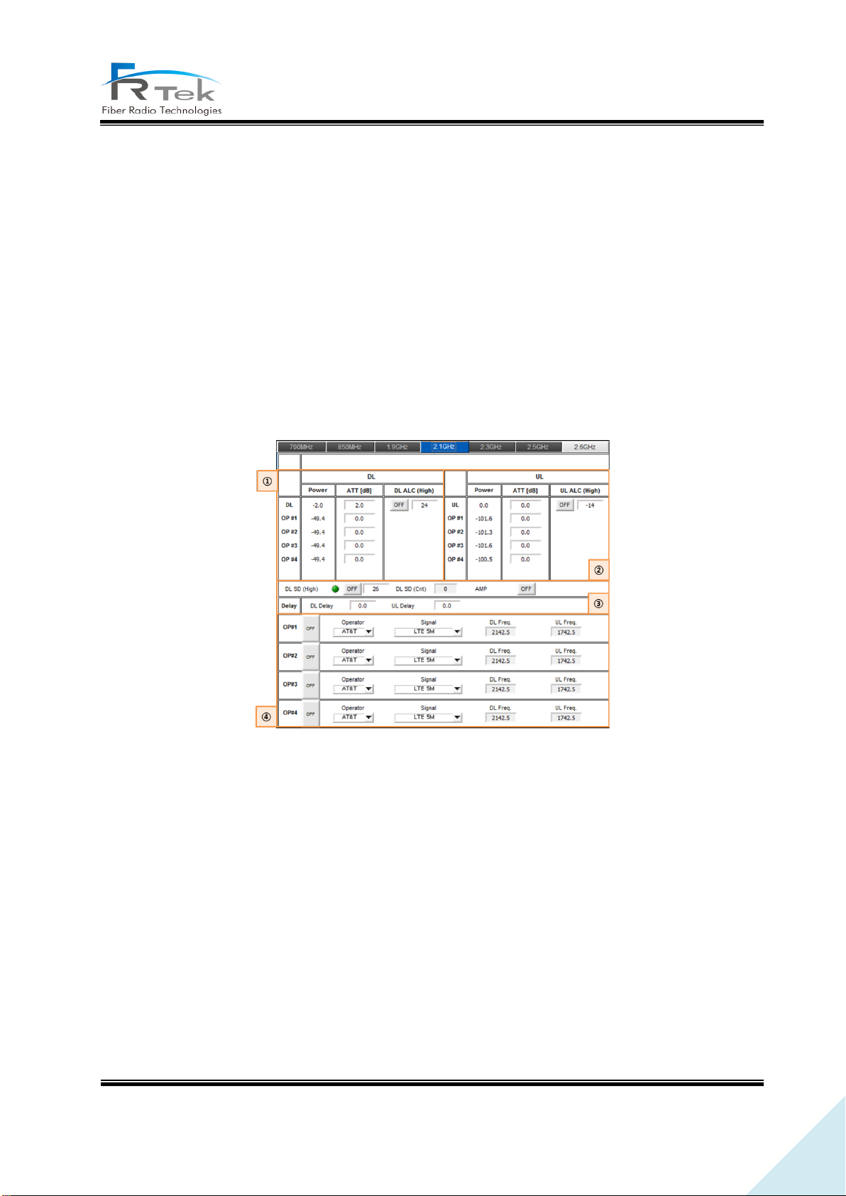
Figure 22. 1.9GHz ERU Band Information Screen.
① 1.9GHz TX Signal Monitoring and Control
The RF signal output level(Downlink) of 1.9GHz band received from the MHU, EHUB can be checked
on this item, and the output level can be manually adjusted by controlling ATTen. according to the
operator. Also, ALC function is configured for the user to automatically adjust output level by inputting
the desired ALC level and turning the function ON.
② 1.9GHz RX Signal Monitoring and Control
The RF signal input level(Uplink) of 1.9GHz band received from the terminal can be checked on
this item. Also, same as TX, input level can be manually adjusted by controlling ATTen., and automatic
input level adjustment through ALC is implemented.
③ 1.9GHz TX Shutdown and Delay Control
PRIVATE AND CONFIDENTIAL © 2019 FRTEK CO., LTD.
Page 52
52
INOVA DAS Operating Manual
Item implements shutdown function of automatically turning HPA off when 1.9GHz TX output signal
gets high due to overpower. User can set shutdown signal level, function operates when switch is on.
Also, item is configured with delay control item to control 1.9GHz system delay. When user inputs
specific value on this delay window, 1.9GHz system delay applies with the user input value added.
④ 1.9GHz Channel Status
Item cannot be controlled on the ERU screen, the operator label, channel filter type, downlink
frequency, uplink frequency set from MHU per each operator can be checked.
• 2.1GHz Band Information
Figure 23. 2.1GHz ERU Band Information Screen.
① 2.1GHz TX Signal Monitoring and Control
The RF signal output level(Downlink) of 2.1GHz band received from the MHU, EHUB can be checked
on this item, and the output level can be manually adjusted by controlling ATTen. according to the
operator. Also, ALC function is configured for the user to automatically adjust output level by inputting
the desired ALC level and turning the function ON.
② 2.1GHz RX Signal Monitoring and Control
The RF signal input level(Uplink) of 2.1GHz band received from the terminal can be checked on
this item. Also, same as TX, input level can be manually adjusted by controlling ATTen., and automatic
input level adjustment through ALC is implemented.
PRIVATE AND CONFIDENTIAL © 2019 FRTEK CO., LTD.
Page 53
53
INOVA DAS Operating Manual
③ 2.1GHz TX Shutdown and Delay Control
Item implements shutdown function of automatically turning HPA off when 2.1GHz TX output signal
gets high due to overpower. User can set shutdown signal level, function operates when switch is on.
Also, item is configured with delay control item to control 2.1GHz system delay. When user inputs
specific value on this delay window, 2.1GHz system delay applies with the user input value added.
④ 2.1GHz Channel Status
Item cannot be controlled on the ERU screen, the operator label, channel filter type, downlink
frequency, uplink frequency set from MHU per each operator can be checked.
• 2.3GHz Band Information
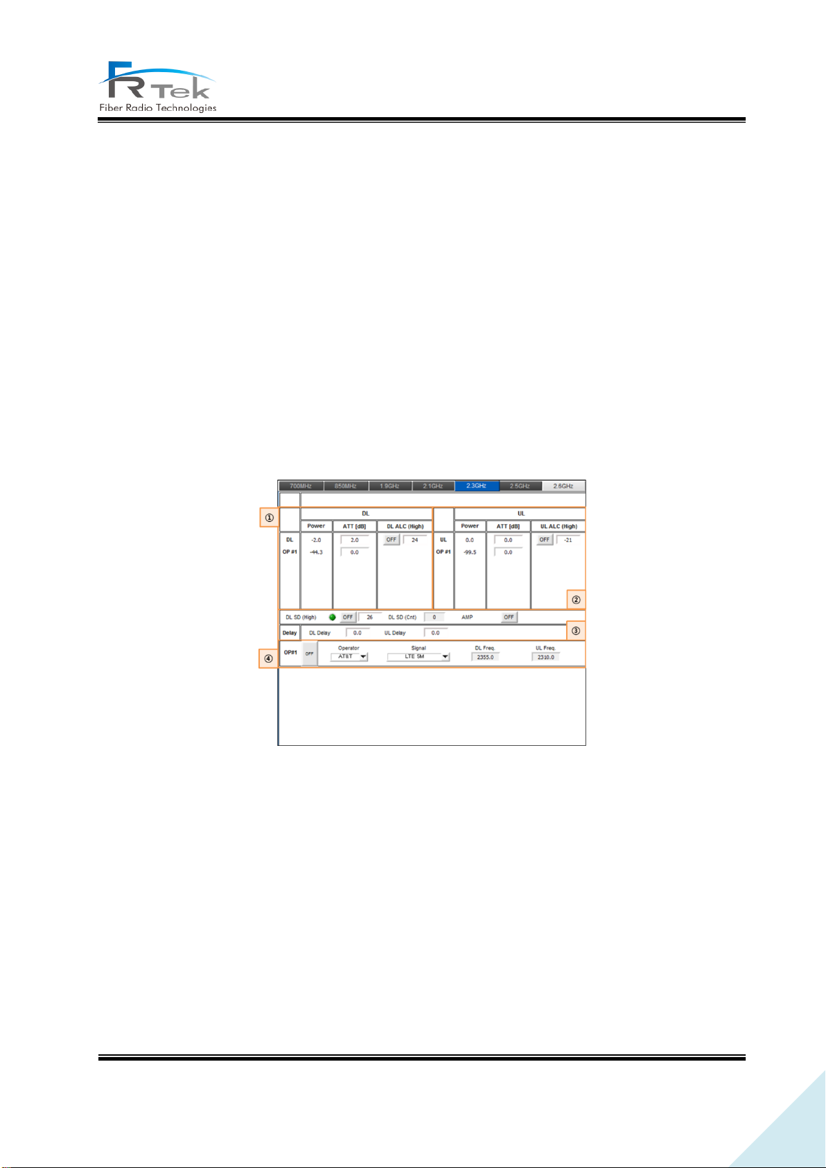
Figure 24. 2.3GHz ERU Band Information Screen.
① 2.3GHz TX Signal Monitoring and Control
The RF signal output level(Downlink) of 2.3GHz band received from the MHU, EHUB can be checked
on this item, and the output level can be manually adjusted by controlling ATTen. according to the
operator. Also, ALC function is configured for the user to automatically adjust output level by inputting
the desired ALC level and turning the function ON.
② 2.3GHz RX Signal Monitoring and Control
The RF signal input level(Uplink) of 2.3GHz band received from the terminal can be checked on
this item. Also, same as TX, input level can be manually adjusted by controlling ATTen., and automatic
PRIVATE AND CONFIDENTIAL © 2019 FRTEK CO., LTD.
Page 54
54
INOVA DAS Operating Manual
input level adjustment through ALC is implemented.
③ 2.3GHz TX Shutdown and Delay Control
Item implements shutdown function of automatically turning HPA off when 2.3GHz TX output signal
gets high due to overpower. User can set shutdown signal level, function operates when switch is on.
Also, item is configured with delay control item to control 2.3GHz system delay. When user inputs
specific value on this delay window, 2.3GHz system delay applies with the user input value added.
④ 2.3GHz Channel Status
Item cannot be controlled on the ERU screen, the operator label, channel filter type, downlink
frequency, uplink frequency set from MHU per each operator can be checked.
• 2.5GHz Band Information
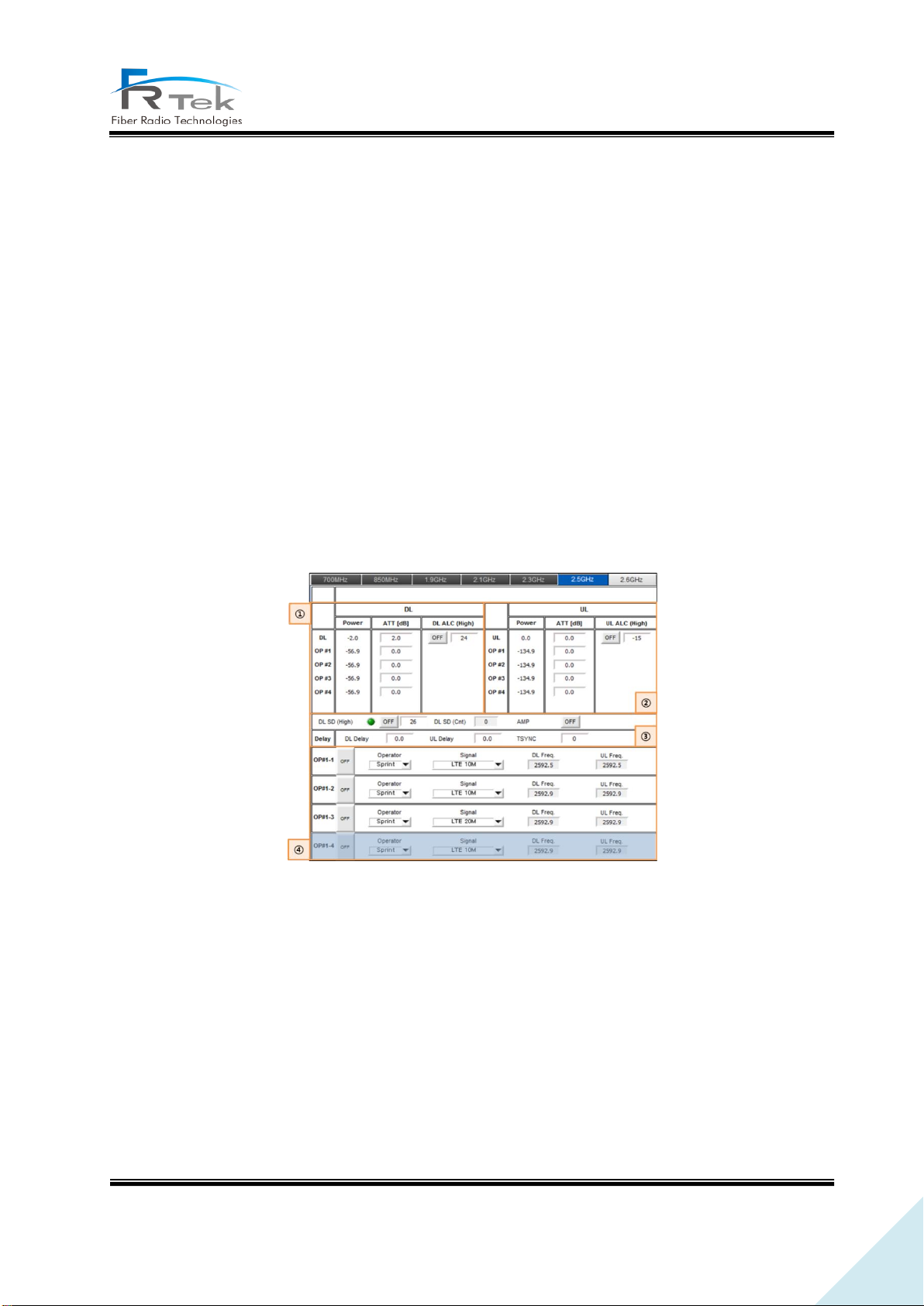
Figure 25. 2.5GHz ERU Band Information Screen.
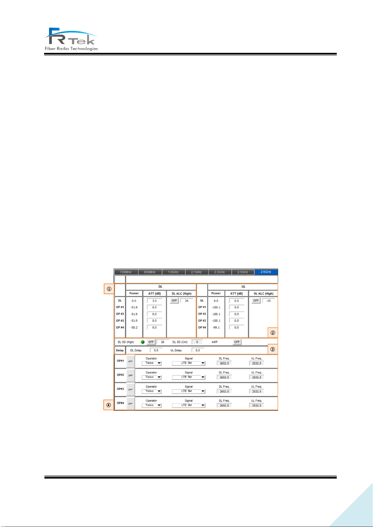
① 2.5GHz TX Signal Monitoring and Control
The RF signal output level(Downlink) of 2.5GHz band received from the MHU, EHUB can be checked
on this item, and the output level can be manually adjusted by controlling ATTen. according to the
operator. Also, ALC function is configured for the user to automatically adjust output level by inputting
the desired ALC level and turning the function ON.
② 2.5GHz RX Signal Monitoring and Control
The RF signal input level(Uplink) of 2.5GHz band received from the terminal can be checked on
PRIVATE AND CONFIDENTIAL © 2019 FRTEK CO., LTD.
Page 55
55
INOVA DAS Operating Manual
this item. Also, same as TX, input level can be manually adjusted by controlling ATTen., and automatic
input level adjustment through ALC is implemented.
③ 2.5GHz TX Shutdown and Delay Control
Item implements shutdown function of automatically turning HPA off when 2.5GHz TX output signal
gets high due to overpower. User can set shutdown signal level, function operates when switch is on.
Also, item is configured with delay control item to control 2.5GHz system delay. When user inputs
specific value on this delay window, 2.5GHz system delay applies with the user input value added.
TSNC item slightly delays total time of the 2.5GHz synchronization signal when user inputs specific
value.
④ 2.5GHz Channel Status
Item cannot be controlled on the ERU screen, the operator label, channel filter type, downlink
frequency, uplink frequency set from MHU per each operator can be checked.
• 2.6GHz Band Information
① 2.6GHz TX Signal Monitoring and Control
The RF signal output level(Downlink) of 2.6GHz band received from the MHU, EHUB can be checked
on this item, and the output level can be manually adjusted by controlling ATTen. according to the
Figure 26. 2.6GHz ERU Band Information Screen.
PRIVATE AND CONFIDENTIAL © 2019 FRTEK CO., LTD.
Page 56

56
INOVA DAS Operating Manual
operator. Also, ALC function is configured for the user to automatically adjust output level by inputting
the desired ALC level and turning the function ON.
② 2.6GHz RX Signal Monitoring and Control
The RF signal input level(Uplink) of 2.6GHz band received from the terminal can be checked on
this item. Also, same as TX, input level can be manually adjusted by controlling ATTen., and automatic
input level adjustment through ALC is implemented.
③ 2.6GHz TX Shutdown and Delay Control
Item implements shutdown function of automatically turning HPA off when 2.6GHz TX output signal
gets high due to overpower. User can set shutdown signal level, function operates when switch is on.
Also, item is configured with delay control item to control 2.6GHz system delay. When user inputs
specific value on this delay window, 2.6GHz system delay applies with the user input value added.
④ 2.6GHz Channel Status
Item cannot be controlled on the ERU screen, the operator label, channel filter type, downlink
frequency, uplink frequency set from MHU per each operator can be checked.
PRIVATE AND CONFIDENTIAL © 2019 FRTEK CO., LTD.
Page 57

57
INOVA DAS Operating Manual
Chapter 7
Alarm and Corrective Action
7.1 Alarm Phenomenon and Solution
PRIVATE AND CONFIDENTIAL © 2019 FRTEK CO., LTD.
Page 58
58
INOVA DAS Operating Manual
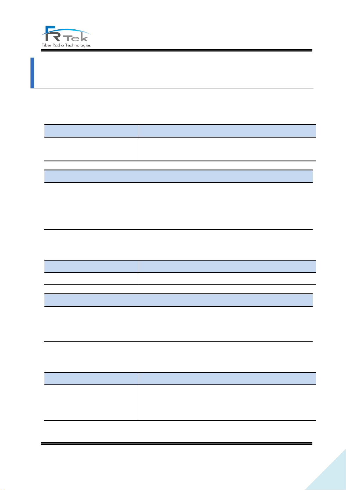
Phenomenon
Cause
- Alarm window: green → red
- MHU : When TX PLL within MRFU is abnormal
- ERU : When TX PLL within ERFU is abnormal
Solution and Action
- Solution : Replace MRFU for MHU, replace ERFU for ERU
- Action : For MHU, replace MRFU of frequency band that alarm generated and check if it works
normally, for ERU, same as MHU, replace ERFU of frequency band that alarm generated
and check if it works normally
Phenomenon
Cause
- Alarm window: green → red
- When TX output level is higher than shutdown alarm set value
Solution and Action
- Solution: Set to appropriate TX ATTen.
- Action: Set TX ATTen. appropriately according to the environment, turn ALC on and prevent
shutdown.
Phenomenon
Cause
- Alarm window : green → red
- When DTU board abnormality such as DTU board connection
harness, DTU board clock, DTU board telecommunication
abnormality occurs
Alarm and Corrective Action
7.1 Alarm Phenomenon and Solution
7.1.1 TX/RX PLL Alarm
7.1.2 TX S/D(High) Alarm
7.1.3 DTU Alarm
PRIVATE AND CONFIDENTIAL © 2019 FRTEK CO., LTD.
Page 59
59
INOVA DAS Operating Manual
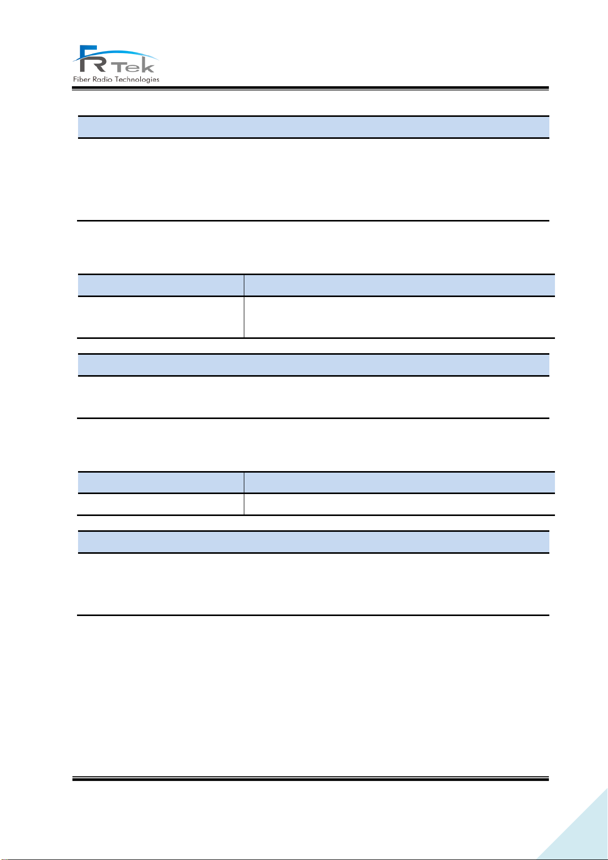
Solution and Action
- Solution : Replace DTU board connection harness or if abnormality still occurs after 10MHz
reference signal input replace DTU board.
- Action : Check DTU board connection harness, input reference signal and replace DTU board and
check if it works normally.
Phenomenon
Cause
- Alarm window: green → red
- When telecommunication between DTU board and CPU
abnormality occurs
Solution and Action
- Solution : Check DTU board and back board connection status and check reference clock
- Action : Check DTU board connection status and replace DTU board
Phenomenon
Cause
- Alarm window: green → red
- When unit temperature is over 80℃
Solution and Action
- Solution : Turn ON internal or external FAN
When AMP temperature is abnormal, change ERFU of relevant frequency band
- Action: When AMP is abnormal, change ERFU integration module and check if it works normally.
7.1.4 DTU Link Fail Alarm
7.1.5 Over Temp
PRIVATE AND CONFIDENTIAL © 2019 FRTEK CO., LTD.
 Loading...