

Page 1
INOVA DAS Operating Manual
1
INOVA DAS
Operating Manual
Document Reference
Company: Fiber Radio Technologies
Version: Ver 1.2
Document Status: Release 1
Issue Date: 2018. 10.
Department: R&D Group 2
Author Manager:
Jun Hyun, Lee
PRIVATE AND CONFIDENTIAL © 2018 FRTEK CO., LTD.
Page 2

INOVA DAS Operating Manual
PRIVATE AND CONFIDENTIAL © 2018 FRTEK CO., LTD.
2
Please read this service manual before installation and operation. Use the system only in accordance with contents of this manual.
The specification and information regarding the products in this manual are subject to change due to updates to system functionality or
system revision changes without notice. For the latest revision of this manual or for technical inquiries, please contact below :
Company Address : 181 Metro Drive, Suite 580, San Jose, CA 95110
Homepage : http://www.frtek.com
Contact for technical inquires or troubleshooting.
Telephone : 330-622-2911 or 510-390-1939
▪
Copyright
The copyright of this manual is from FRTek Co., Ltd.
This manual may not be reproduced, distributed, modified on any form without the consent of FRTek
Co., Ltd
Unauthorized disclosure, distribution, copying or use of the information contained in this document in
whole or in part without authority is strictly prohibited.
▪
Trademark
The trademarks mentioned in this manual are registered trademarks of the respective company.
Page 3
INOVA DAS Operating Manual
PRIVATE AND CONFIDENTIAL © 2018 FRTEK CO., LTD.
3
Version
Issue Date
Details of Revision
Author
Authorizing
Manager
V 1.0
18. 09. 12.
Original
Jun Hyun, Lee
V 1.1
18. 10. 17.
1
st
Revision
Jun Hyun, Lee
V 1.2
18. 10. 22.
2
nd
Revision
Jun Hyun, Lee
Revision History
This manual is produced by R&D Group 2 Printed in FRTek.
Page 4

INOVA DAS Operating Manual
PRIVATE AND CONFIDENTIAL © 2018 FRTEK CO., LTD.
4
Chapter 1
Safety & Certification Notice
1.1
FCC/IC Warning Statements
Page 5

INOVA DAS Operating Manual
PRIVATE AND CONFIDENTIAL © 2018 FRTEK CO., LTD.
5
Safety & Certification Notice
1.1
FCC/IC Warning Statements
1.1.1
FCC Part 15.105 statement
-
This equipment has been tested and found to comply with the limits for a Class A digital device.
-
These limits are designed to provide reasonable protection against harmful interference when the
equipment is operated in a commercial environment.
-
This equipment generates, uses, and can radiate radio frequency energy and, if not installed and
used in accordance with the instruction manual, may cause harmful interference to radio
communications.
-
Operation of this equipment in a residential area is likely to cause harmful interference in which
case the user will be required to correct the interference at his own expense.
1.1.2
FCC Part 15.21 statement
-
Any changes or modifications not expressly approved by the party responsible for compliance could
void the user's authority to operate this equipment
1.1.3
Health and Safety Warnings
-
This system can be operated by approved operator only and operator should observe the warning
sentence of operating manual.
-
The operator who can install, operate or handle related system service should acquaint themselves
this manual.
-
Control and configuration of this system should be set up according to purpose of use (Refer to the
manufacturer’s product information), it has to be satisfied prescribed request items.
-
Operator should turn off the main power switch before installing system, maintenance and related
works.
-
If this product is disassembled intentionally, it can bring electric shock, breakdown, malfunction and
static with losing life and property. Do not disassemble, repair and modify product.
-
This system cover should be (door) securely fastened in open position, e.g. by tying it up, at outdoor
Page 6
INOVA DAS Operating Manual
PRIVATE AND CONFIDENTIAL © 2018 FRTEK CO., LTD.
6
Warning
Warning
Warning
work in order to prevent door from slamming due to wind causing bodily harm or damage.
-
Due to power dissipation, the remote unit may reach a very high temperature. Do not operate this
equipment on or close to flammable materials. Use caution when servicing the unit.
-
Use this equipment only for the purpose specified by the manufacturer. Do not carry out any
modifications or fit any spare parts, which are not sold or recommended by the manufacturer. This
could cause fires, electric shock or other injuries.
-
Read and obey all the warning labels attached to the unit. Make sure that all warning labels are
kept in a legible condition.
-
It is the responsibility of the network provider to implement prevention measures to avoid health
hazards associated with radiation from the antenna(s) connected to the unit.
-
Do not use any solvents, chemicals, or cleaning solutions containing alcohol, ammonia, or abrasives.
-
Although the remote unit is internally protected against overvoltage, it is strongly recommended to
ground (earth) the antenna cables close to the repeater’s antenna connectors for protection against
atmospheric discharge.
Obey all general and regional installation and safety regulations relating to work on high
voltage installations, as well as regulations covering correct use of tools and personal protective
equipment.
Use of unauthorized antennas, cables, and /or coupling devices not conforming with ERP/EIRP and
/or indoor‐only restrictions is prohibited.
Laser radiation! Do not stare into the beam; do not view it directly or with optical instruments.
Page 7

INOVA DAS Operating Manual
PRIVATE AND CONFIDENTIAL © 2018 FRTEK CO., LTD.
7
maintained between the radiator (antenna) and all persons at all times. This device must not be co-
located or operating in conjunction with any other antenna or transmitter.
Under Industry Canada regulations, this radio transmitter may only operate using an antenna of a
type and maximum (or lesser) gain approved for the transmitter by Industry Canada. To reduce
potential radio interference to other users, the antenna type and its gain should be so chosen that
the equivalent isotropically radiated power (e.i.r.p.) is not more than that necessary for successful
communication.
Conformément à la réglementation d’Industrie Canada, le présent émetteur radio peut
fonctionneravec une antenne d’un type et d’un gain maximal (ou inférieur) approuvé pour l’émetteur
par
Industrie Canada. Dans le but de réduire les risques de brouillage radioélectrique à l’intention
desautres utilisateurs, il faut choisir le type d’antenne et son gain de sorte que la puissance
isotroperayonnée quivalente (p.i.r.e.) ne dépassepas l’intensité nécessaire à l’établissement d’une
communication satisfaisante.
Please be informed that the temperature of the surface is too high.
Please be careful. The label is attached to the front of the equipment
and the PSU (Power Supply Unit).
•
[FCC] RF Exposure Statement
The antenna(s) must be installed such that a minimum separation distance of at least 20cm is
•
[IC] RSS-GEN, Sec. 7.1.2 – (transmitters)
Page 8
INOVA DAS Operating Manual
PRIVATE AND CONFIDENTIAL © 2018 FRTEK CO., LTD.
8
This equipment complies with RF radiation exposure limits set forth for an uncontrolled
between the radiator and your body. This transmitter must not be co-located or operating in
conjunction with any other antenna or transmitter. RF exposure will be addressed at time of
installation and the use of higher gain antennas require larger separation distances.
L’antenne (ou les antennes) doit être installée de façon à maintenir à tout instant une distance
Cet appareil ne doit pas être installé ou utilisé en conjonction avec une autre antenne ou émetteur.
•
RF Radiation Exposure
environment. This equipment should be installed and operated with a minimum distance of 20 cm
minimum de au moins 20cm entre la source de radiation (l’antenne) et toute personne physique.
Page 9

INOVA DAS Operating Manual
PRIVATE AND CONFIDENTIAL © 2018 FRTEK CO., LTD.
9
Chapter 2
System Overview
2.1
2.2
System Overview
System Network Configuration
Page 10
INOVA DAS Operating Manual
PRIVATE AND CONFIDENTIAL © 2018 FRTEK CO., LTD.
10
This equipment’s simple information are :
■ Bluetooth V 2.0 / Class 1
■ Output Transmit Power: 9.5dBm to 11.1dBm.
■ Size : 27.1 X 14.8 X 2.6mm (Shield case)
■ Operating Temperature: -40°c ~ +85°c
System Overview
2.1
System Overview
INOVA DAS is a system that can provide high quality telecommunication quality and data
telecommunication service both in-building and outdoor. Also, this system is a DAS (Distributed Antenna
System) system, a digital system capable of accommodating a plurality of frequency bands, available
for public and private facilities.
INOVA DAS system can be installed in:
-
Shopping Malls
-
Hotels
-
Campus
-
Airports
-
Subways
-
Stadiums and convention centers, etc
INOVA DAS contains Bluetooth module (SBM-2715-C1)
This module is just operated for status monitoring and control parameters from server, software for DAS
download and signal quality measurement. So, there is no simultaneous transmission between Bluetooth
module and other wireless modules within Booster transmitter since real Booster signal is not transmitted
through Bluetooth module.
Page 11

INOVA DAS Operating Manual
PRIVATE AND CONFIDENTIAL © 2018 FRTEK CO., LTD.
11
Chapter 3
System Configuration
3.1
ROU 2W Configuration
3.2
ROU 5W Configuration
Page 12
INOVA DAS Operating Manual
PRIVATE AND CONFIDENTIAL © 2018 FRTEK CO., LTD.
12
Item
Content
Remark
Size
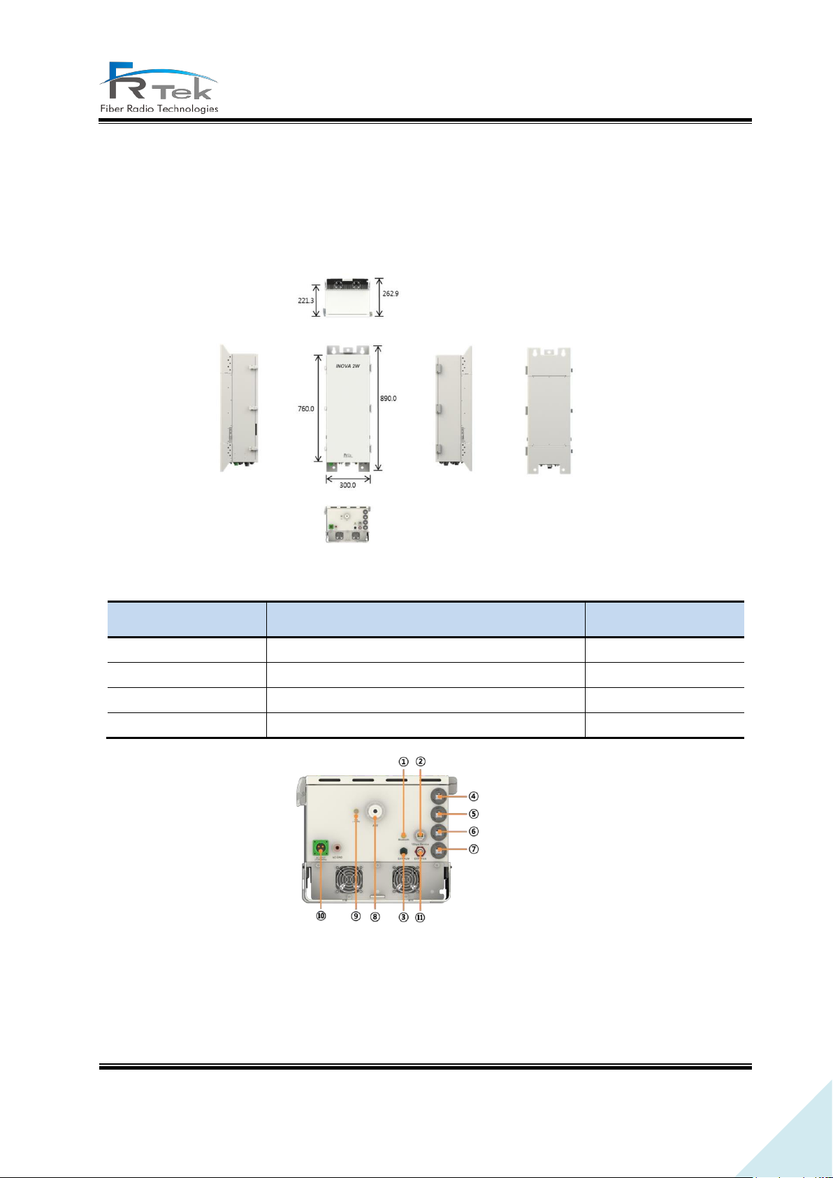
300 * 890 * 262.9 (W * H * D)
Including bracket
Weight
Approx. 39kg
Input power
AC 120V (60Hz)
Environment
In-building type
3.1 ROU 2W Configuration
ROU 2W is a structure that can be used in-building, enclosure is minimized considering installation
space and operator's convenience. ROU 2W is configured with RPSU, RDTU, RCPU, 6 RRFUs(ROU RF
unit) and supports up to 6 frequency bands.
Figure 11. ROU 2W
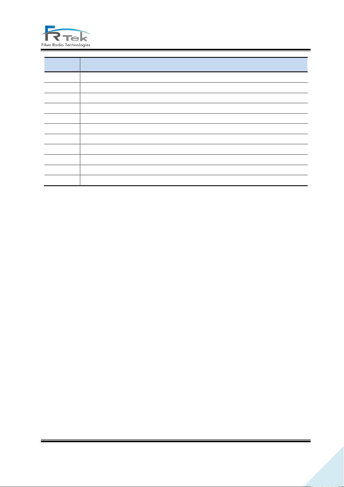
Figure 12. ROU 2W Port Configuration.
Page 13
INOVA DAS Operating Manual
PRIVATE AND CONFIDENTIAL © 2018 FRTEK CO., LTD.
13
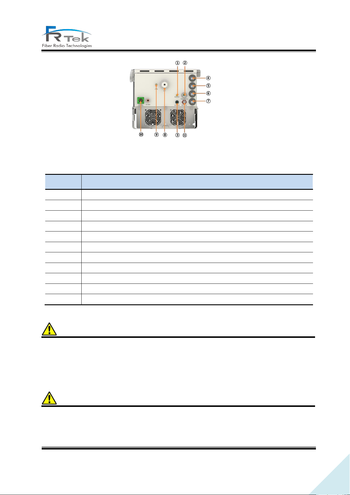
No
Content
①
Bluetooth antenna port
②
1Gbps service port
③
External alarm port
④
MHU/ROU Single OPTIC port
⑤
MHU/ROU Extend OPTIC port
⑥
Reserved OPTIC port (Single Sectorization or 5G interlink)
⑦
Reserved OPTIC port (Extend Sectorization or 5G interlink)
⑧
ANT port
⑨
Coupling port
⑩
AC power input port
⑪
EXT FAN input port
Page 14
INOVA DAS Operating Manual
PRIVATE AND CONFIDENTIAL © 2018 FRTEK CO., LTD.
14
Item
Content
Remark
Size
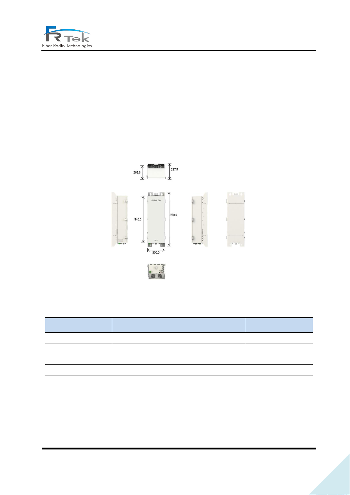
300 * 970 * 287.9 (W * H * D)
Including bracket
Weight
Approx. 50kg
Input power
AC 120V (60Hz)
Environment
In-building/outdoor type
3.2 ROU 5W Configuration
ROU 5W is a structure for in-building and outdoor, minimized enclosure considering installation space
and operator's convenience. ROU 5W, same as ROU 2W, is configured with RPSU, RDTU, RCPU, 6
RRFUs (ROU RF unit), and supports up to 6 frequency bands. Also, functions of ROU 5W are the same
as ROU 2W. Below picture shows the ROU 5W figure.
Figure 13. ROU 5W.
Page 15
INOVA DAS Operating Manual
PRIVATE AND CONFIDENTIAL © 2018 FRTEK CO., LTD.
15
No
Content
①
Bluetooth antenna port
②
1Gbps service port
③
External alarm port
④
MHU/ROU Single OPTIC port
⑤
MHU/ROU Extend OPTIC port
⑥
Reserved OPTIC port (Single Sectorization or 5G interlink)
⑦
Reserved OPTIC port (Extend Sectorization or 5G interlink)
⑧
ANT port
⑨
Coupling port
⑩
AC power input port
⑪
EXT FAN input port
Warning
Warning
Figure 14. ROU 5W Port Configuration.
Maximum output for ROU 5W differs from each frequency band, should be operated with reference
to system specification.
When HPA is ON through ROU GUI for service, connection status between ROU output port and
antenna must be checked.
Page 16

16
INOVA DAS Tune-up Procedure
Chapter 3
Bluetooth Connection
3.1 Bluetooth Connection
LTD.
PRIVATE AND CONFIDENTIAL © 2018 FRTEK CO.,
Page 17

17
INOVA DAS Tune-up Procedure
3.1 Bluetooth Connection
INOVA DAS is implemented with Bluetooth function for user's convenience. ROU is
configured with Bluetooth port, and GUI access is available remotely through Bluetooth.
Connect Bluetooth antenna to ROU’s Bluetooth port, and turn on the ROU power. Then
go to the control panel - hardware and sound - device and printer window, click right
button of the mouse and click the add device button.
In the list of devices to be added, the Bluetooth module available for connection will be
searched. Please select the I-STORM module from the list. The Bluetooth name can be
changed by setting, if the device cannot be searched, recheck the connection between the
Bluetooth and the Main Board.
Click on 'enter the device connection code' item. Then input the device connection code.
(Default : 1234)
When the device connection code has been correctly input, window will show as the
above picture. When the window appears, click the 'close' button.
Open the Device manager window, and check if 2 new Comports are added in the PC.
Normally it would take 10~15 seconds to confirm. Also, the Comport number will be set
randomly.
Access the Local GUI, and check the Comport assigned to the Bluetooth. Select the faster
number of the Comport number and access to GUI. (If there are COM23 and COM24, then
select COM23.)
CO., LTD.
PRIVATE AND CONFIDENTIAL © 2018 FRTEK
Page 18

INOVA DAS Operating Manual
92
Chapter 4
System Installation
4.1 Tools
4.2 ROU 2W Installation
4.3 ROU 5W Installation
Page 19
INOVA DAS Operating Manual
92
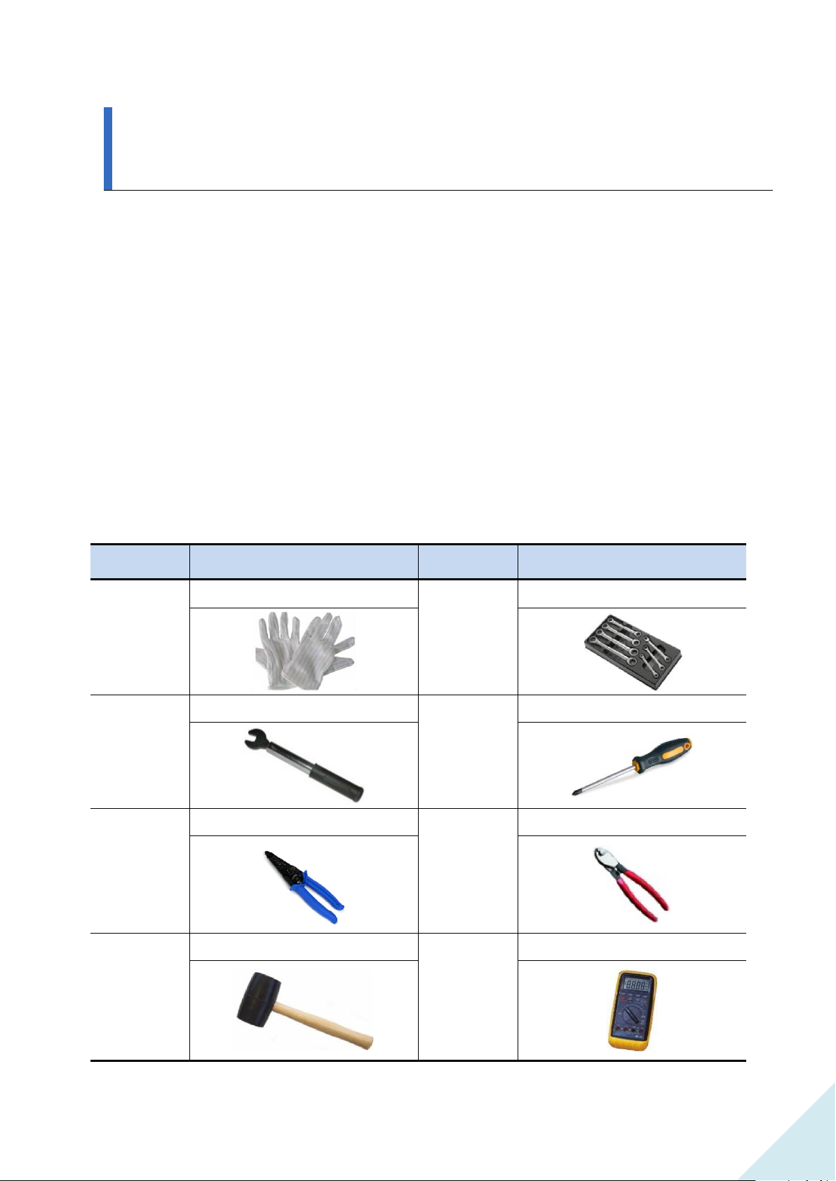
No.
Tools
No.
Tools
1
ESD Gloves
2
Torque Wrench Set
3
33mm Torque Wrench
4
+, 3Φ Screw Driver
5
Wire Stripper
6
Wire Cutter
7
Rubber Mallet
8
Digital Multi-meter
System Installation
“ This manual is to provide product installation method and product information to the user
operating the INOVA DAS system, the repeater manager who uses the operation manual needs to
require professional knowledge and experience on construction operation of repeater systems. “
This chapter explains how to connect power cables and how to install each equipment and optic
cable. It specifically describes MHU (MWDM, MPSU, MDRU, MBIU), ROU 2W, ROU 5W installation
method and cable connecting method.
4.1 Tools
Tools needed for installation are as below.
Page 20
INOVA DAS Operating Manual
92
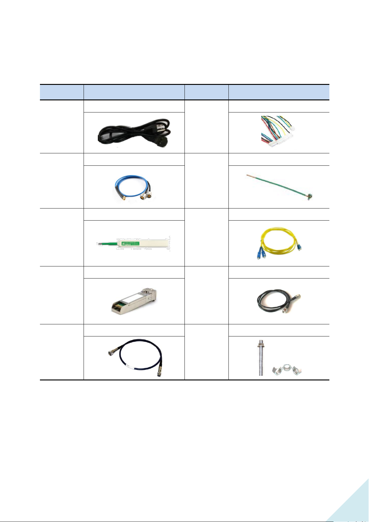
No.
Tools
No.
Tools
1
AC Cable
2
INOVA Harness Cable
3
INOVA RF Cable
4
Ground Wire Line
5
Optic Connector Cleaner
6
LC-type Optic Fiber
7
Optic Module
8
SMA Cable
9
ANT RF Cable
10
Bracket Bolt/Nut
Other cables and components needed for installation are as below.
Page 21
INOVA DAS Operating Manual
92
4.2 ROU 2W Installation
4.2.1 Product Installation
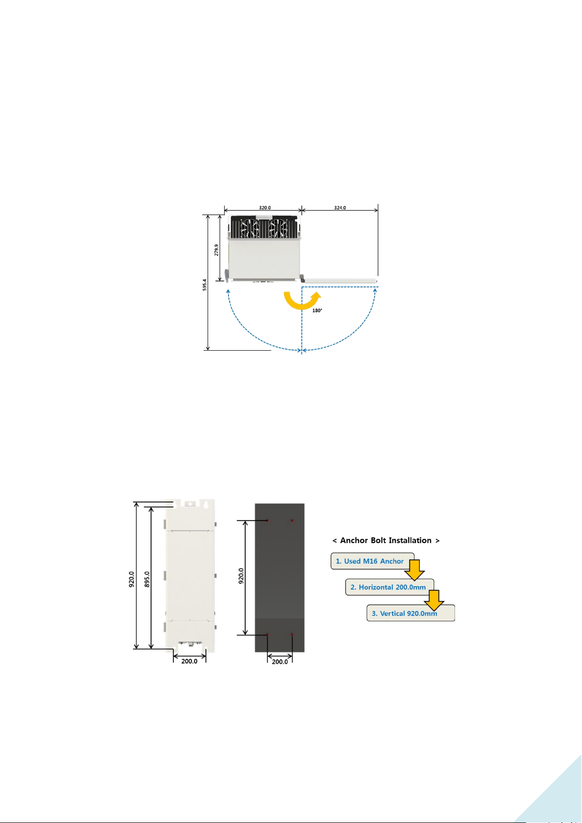
ROU 2W is configured to one enclosure, can be installed to wall through mounting bracket.
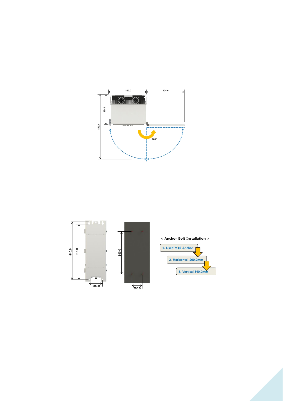
Figure 1. ROU 2W needed Door space.
Since ROU 2W is configured with door, for ease of process, 324mm space on the equipment
right side must be secured, and more than 570mm installation space is needed from installation
wall.
Figure 2. ROU 2W Anchor Bolt Assemble.
Above figure is a simple drawing for the wall face. For wall installation of ROU 2W, use anchor
bolt to fix.
Page 22
INOVA DAS Operating Manual
92
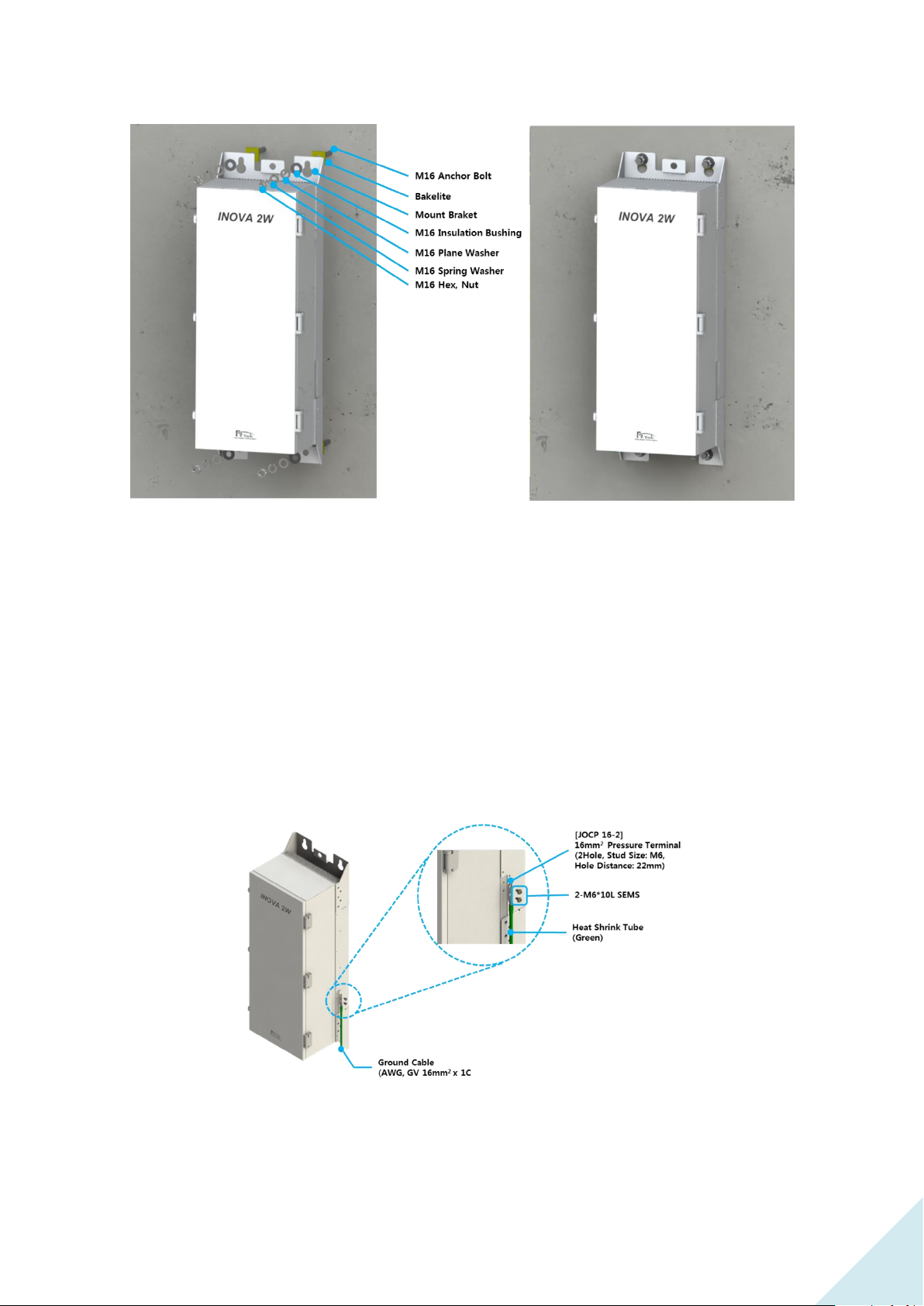
Figure 3. ROU 2W Wall Installation Assemble.
Above figure is the assemble drawing of ROU 2W's wall installation. The assemble orders are as
below.
1. Insert bake lite to M16 Anchor Bolt, and locate ROU 2W according to M16 Anchor Bolt
location.
2. Insert M16 Insulation Bushing, M16 Plane Washer, and M16 Spring Washer.
3. Tighten M16 Hex, Nut using spanner.
4.2.2 Ground Cable Connection
Enclosure grounding and building grounding is connected in order to stable and protect ROU
2W equipment from electrical danger.
Figure 4. ROU 2W Ground Cable Connection.
Page 23
INOVA DAS Operating Manual
92
MS Connector
Pin Name
Name
Description
Length(mm)
A
AC_H
AC Hot
1800
B
AC-N
AC Neutral
1800
C
F.G
Frame Ground
1800
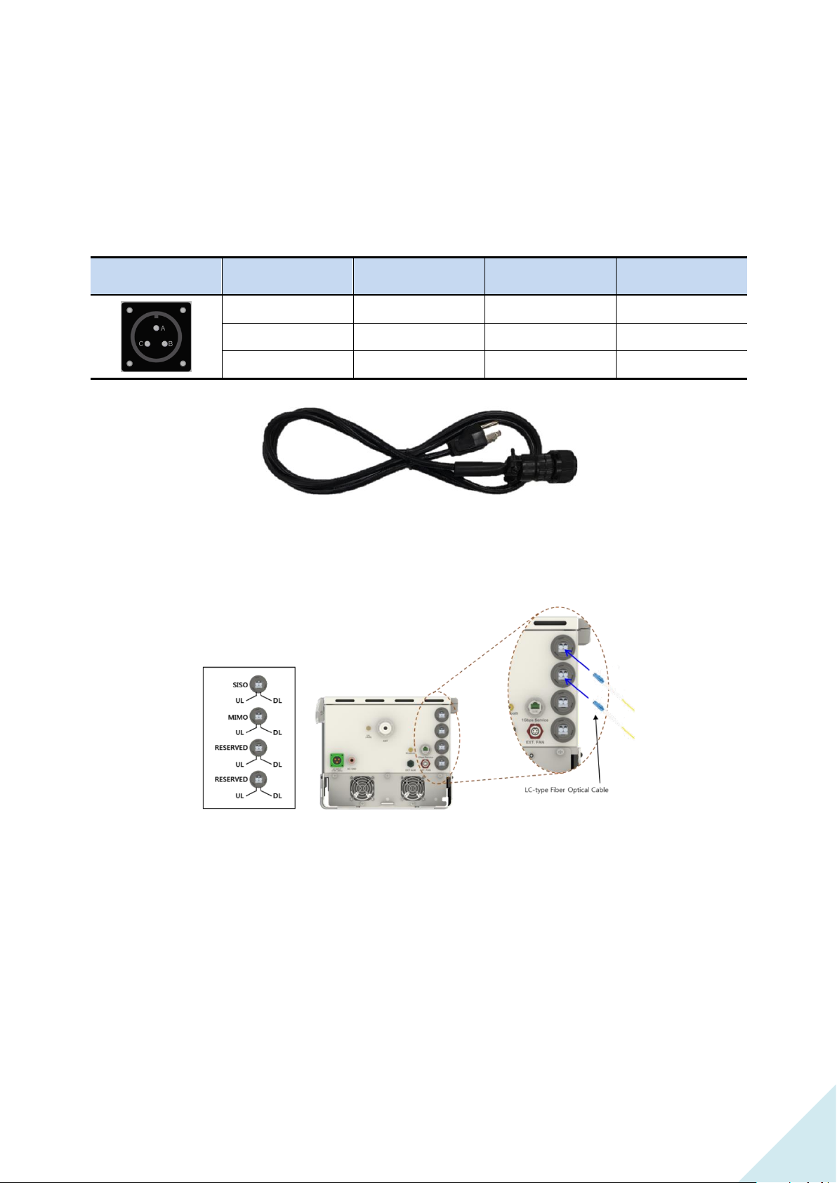
4.2.3 Power Cable Connection
ROU 2W uses AC120V(60Hz) as main power, and power cable includes plug. Below is the pin
specification of AC power cable, when connecting power, polarity of each pin must be checked.
Figure 5. ROU 2W의 Power Cable.
4.2.4 Optic Cable Connection
Figure 6. ROU 2W Optic Cable Connection.
Since ROU 2W is in-building equipment, it does not necessarily have to use waterproof optic
cable. ROU 2W is configured with a total of 4 optic ports. First optic port for SISO operation is
generally connected to MHU, and also used for cascade network expansion through lower ROU
installation. Second optic port is used for MIMO expansion, third and forth port are configured for
spare optic ports. Optic cable connected from MHU or upper ROU is connected with first optic
port for service operation.
Page 24
INOVA DAS Operating Manual
92
4.3 ROU 5W Installation
4.3.1 Product Installation
ROU 5W is configured with one enclosure, installation on wall is available through mounting
bracket.
Figure 7. ROU 5W Needed Door Space.
Since ROU 5W is, same as ROU 2W, configured with door, for ease of process, 324mm space on
the equipment right side must be secured, and more than 570mm installation space is needed
from installation wall.
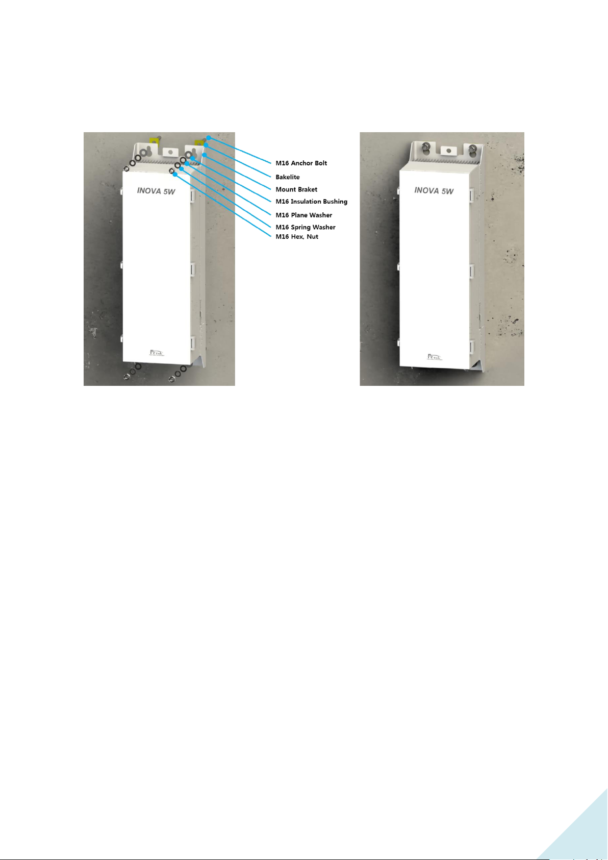
Above figure is a simple drawing of the wall face. For wall face installation of ROU 5W, anchor
Figure 8. ROU 5W Anchor Bolt Assemble.
Page 25
INOVA DAS Operating Manual
92
bolt is used to fix.
Figure 9. ROU 5W Wall Face Installation Assemble.
Above figure is a assemble drawing of wall face installation of ROU 5W. Assemble order is as the
following.
1. Insert bakelite to M16 Anchor Bolt, and locate ROU 5W according to M16 Anchor Bolt
location.
2. Insert M16 Insulation Bushing, M16 Plane Washer, and M16 Spring Washer.
3. Tighten M16 Hex, Nut using spanner.
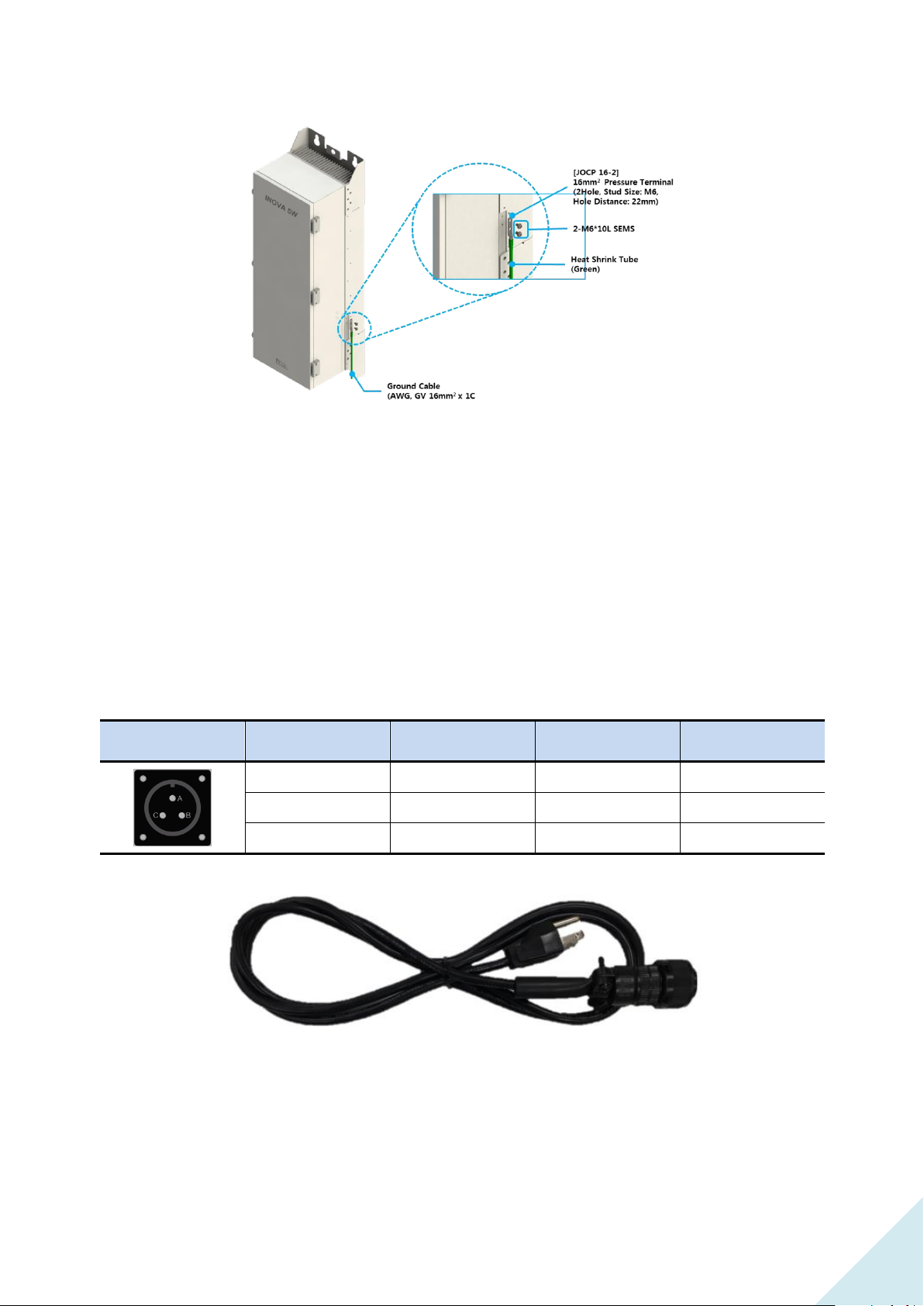
4.3.2 Ground Cable Connection
Page 26
INOVA DAS Operating Manual
92
MS Connector
Pin Name
Name
Description
Length(mm)
A
AC_H
AC Hot
1800
B
AC-N
AC Neutral
1800
C
F.G
Frame Ground
1800
Figure 10. ROU 5W Ground Cable Connection.
Same as ROU 2W, Enclosure grounding and building grounding is connected in order to stable
and protect ROU 5W equipment from electrical danger.
4.3.3 Power Cable Connection
Same as ROU 2W, ROU 5W uses AC power cable, and when connecting power, polarity of each
pin must be checked.
Figure 11. ROU 5W Power Cable.
Page 27
INOVA DAS Operating Manual
92
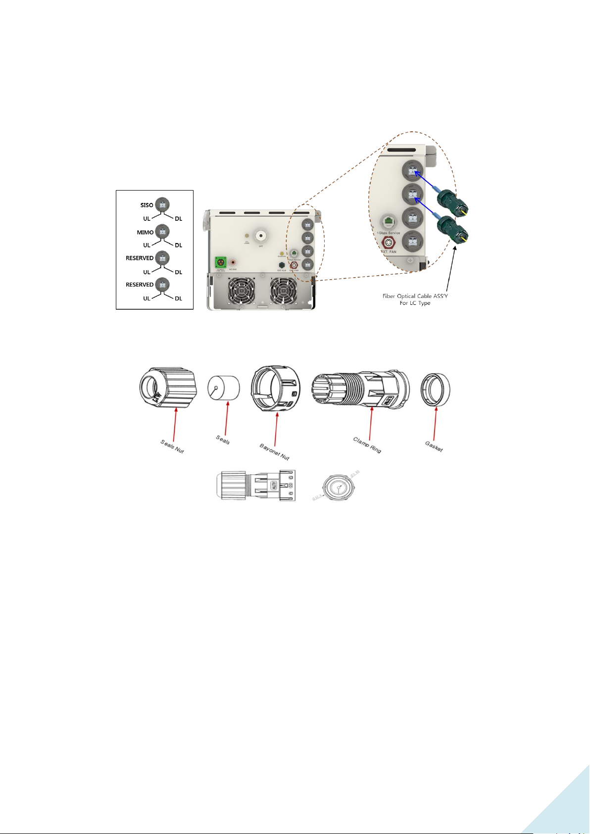
4.3.4 Optic Cable Connection
Figure 12. ROU 5W Optic Cable Connection.
Figure 13. ROU 5W Waterproof Type Optic Connector.
Since ROU 5W is also installed and operated outdoors, waterproof type optic cable must be used
for outdoor use. Above figure shows information of the optic cable connection method and
waterproof type optic connector.
Page 28
INOVA DAS Operating Manual
92
 Loading...