

Frosty Factory 127 Service Manual

1
Frosty Factory
of America, Inc.
2301 S. Farmerville St., Ruston, LA 71270
frostyfactory.com
(318) 255-1162 (800) 544-4071 (318) 255-1170 fax
Service Manual
All technical data, pictures and drawings contained in this manual are not binding on the
manufacturer nor can the manufacturer be held liable for any modifications to the machine in whole
or in part. Revised 1/2016

2
TABLE OF CONTENTS
1.0 INTRODUCTION
1.1 Use of the Manual
1.2 Preliminary Inspection
1.3 Description
1.4 Dimensions
2.0 LOCATION AND INSTALLATION
2.1 Safety Precautions
2.2 Installation
3.0 OPERATION
3.1 Machine Controls
3.2 The Product You Serve
3.3 Product Consistency
3.4 Start Up
3.5 Freeze Time
4.0 MAINTENANCE
4.1 Cleaning
4.2 Re-Assembly
4.3 Preventative Maintenance
4.4 Extended Storage
4.5 Troubleshooting
4.6 Rear Cylinder and Drive Assembly Parts List
4.7 Faceplate and Faucet Assembly
4.8 Float Switch Assembly
4.9 Thermostat Assemblies
4.10 Using the Cleaning Brushes
4.11 Scraper Blade and Spring Seal Installation
4.12 Beater Seal Assembly
4.13 Ceramic Seal Removal and Re-installation
5.0 SPARE PARTS LIST
6.0 FACTORY ASSISTANCE
7.0 ELECTRICAL SCHEMATIC
8.0 WIRE DRAWING
9.0 WARRANTY
3
SECTION 1
CAUTION
RISK OF ELECTRICAL SHOCK.
DISCONNECT POWER
BEFORE SERVICING UNIT.
CAUTION
MOVING PARTS
DO NOT OPERATE UNIT
WITH PANELS REMOVED
WARNING
DO NOT INSERT ANY OBJECTS
INTO CYLINDER OR HOPPER WHILE
MACHINE IS RUNNING!
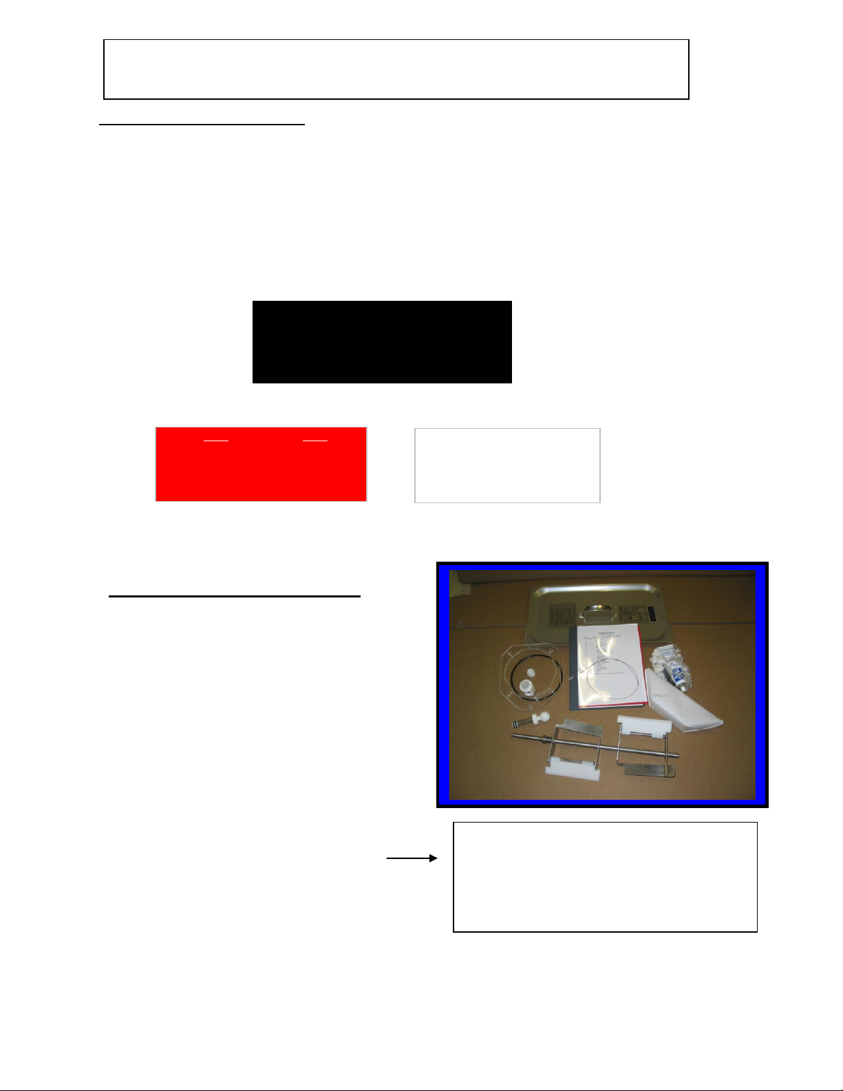
Long Beater Bar, Drip Tray, Faceplate,
Faceplate Knobs, Hopper Cover, PetroGel, Sanitizer, Spare Faucet O-Rings,
Warranty Card, Wire Brushes and
Skirts (Not shown).
1.2 PRELIMINARY INSPECTION
Unpack the unit as soon as possible upon
its arrival. Check the entire machine and
its contents for possible shipping damage.
Note damage, if any, and notify your
carrier immediately. All machines are
shipped FOB Ruston, Louisiana, which
means that the machines left our docks in
perfect working order. Frosty Factory of
America is not responsible for damaged
merchandise once the equipment leaves
our dock. Inventory the accessories to be
sure they include the items you specified
on your order. Normally the accessories
include:
INTRODUCTION
1.1 USE OF THIS MANUAL
Your service manual has been prepared as a guide to help you get the most from your Frozen
Drink Machine. It contains information about the installation and operation of your machine.
The manual also contains instructions for service and care. The manual should be read carefully
by the operator of the Frozen Drink Machine to become familiar with the machine and the
correct operating procedures described within. The following notations are used throughout the
manual to bring important facts to your attention:
“Warning” - This notation is used whenever the personal safety of the operator(s) might be
jeopardized, if procedures are not followed correctly.
“Caution” - This notation is used whenever the operator may receive or cause injury if not
observed.
“Notice” - This notation is used to bring important information to your attention that will
enhance the performance of your machine.
4
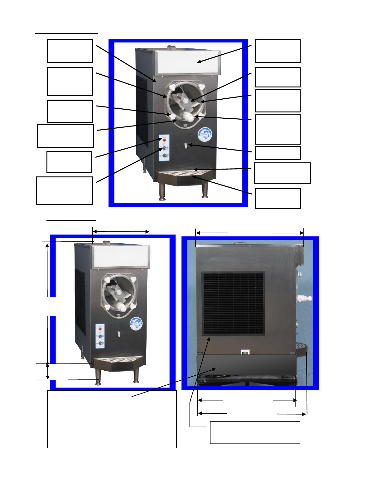
1.3 DESCRIPTION
24.5”
(62.2cm)
1.4 DIMENSIONS
19” (48.2cm)
23 ¾” (60.3 cm)
26” (53.3 cm)
Drip Tube
Lighted
Flavor Sign
Beater Bar
C6530
Faucet
Assembly
C6513
Scraper
Blade C6510
Stainless
Steel Cabinet
Stainless
Steel
Cylinder
Faceplate
Knobs F0262
Clear Plastic
Faceplate C6521
Fill Indicator
Light F0207
12.0” (27.3cm)
Drip Tray Insert
F6604
Note: With skirts installed air intake
will be between the two front legs and
should be near room temperature. If the
intake air is warmer than the room
temperature more exhaust space is
needed at the sides of the machines.
4”
Control Switches
Top F0416
Bottom F0417
Drip Tray
F6603
Allow at least 8” on both sides
of unit for air circulation
5
SECTION 2
LOCATION & INSTALLATION
2.1 SAFETY PRECAUTIONS
Do not attempt to operate your Frozen Drink Machine until the safety precautions and
operating instructions in this manual are read completely and are thoroughly understood.
2.2 INSTALLATION
Placing your Frozen Drink Machine in a highly visible area will enhance sales.
CAUTION: Do not attempt to share the dedicated electrical outlet with any other
appliance; this will cause the circuit breaker to trip.
1. Remove the machine from the shipping container.
2. Place the unit on a sturdy platform able to hold the weight of the machine when full of
product.
3. Level the machine by turning the adjustable part of the leg. The machine should be
level front to back as well as left to right.
4. Air-cooled condensers must have correct ventilation. Air intake is under the
machine (updraft) and discharges through the sides. 18” clearance is recommended on
both sides. In addition, all Frozen Drink Machines require 12” clearance above the
machine.
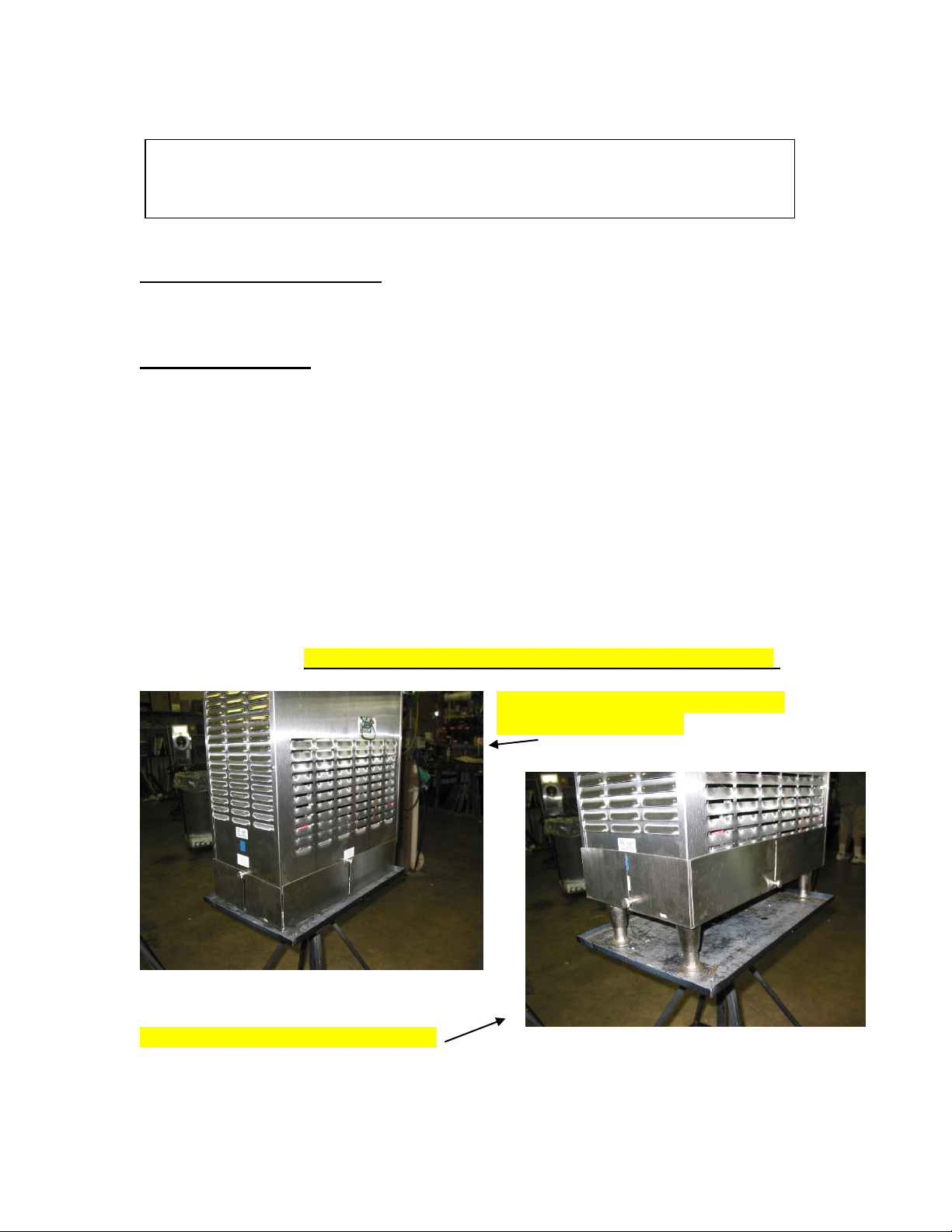
5. Install the skirts! Operation without the skirts will make it take longer to freeze!!
Skirts down for operation. For normal
operation/freezing mode.
Skirts up for transport or carrying mode.
6
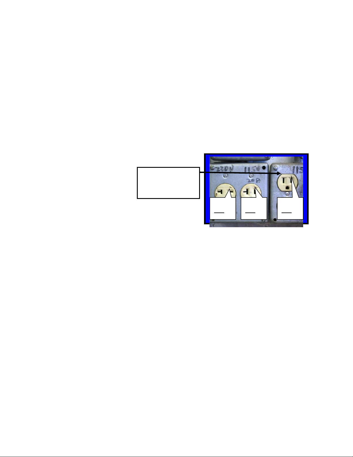
WARNING: Do not
attempt to alter the
electrical plug. Serious
injury or electrocution
may result.
Notice: Your
receptacle should
look like this.
115V
20A
230V
20A
115V
15A
8. Install the drip tray, cover, beater bar and
faceplate assemblies on the Frozen Drink
Machine.
NOTICE: Locating the unit in direct sunlight, near cooking equipment or any high
heat area will reduce the performance of your machine.
CAUTION: Extended operations under severe heat condition can damage the cooling
system.
NOTICE: Establishments that serve beverages from frozen drink machines are
responsible for providing the necessary facilities for cleaning and
sanitizing their food service equipment.
6. Place the three-position switch in the OFF position (center).
7. Connect the power cord. The Frozen Drink Machine must be connected to a properly
grounded receptacle. The electrical cord furnished as part of the Frozen Drink
Machine has a three prong grounding type plug. The use of an extension cord is not
recommended. If one must be used, refer to the national and local electrical codes.
Do not use an adapter to get around grounding requirements.
7
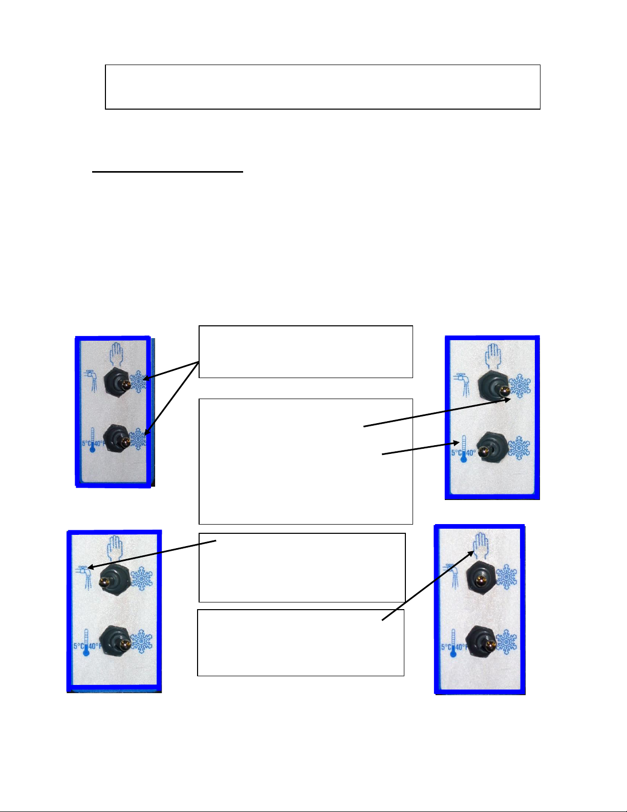
Normal Operation – Both switches on
snowflake. Machine will freeze mix to
provide frozen beverage as desired.
Cleaning Operation - The drive
motor will run in the faucet position
to allow a stirring action of the rinse
water while cleaning.
Off - The hand symbol is the
recognized international symbol for
“stop”. In this position,
the machine will not run.
Cooling Operation – Top switch on
snowflake, Bottom switch on
thermometer symbol. Machine will
automatically come on whenever
necessary to keep mix cooled to
5ºC/40º F - used primarily for
overnight storage of mix remaining
in the machine.
3.1 MACHINE CONTROLS
Two selector switches located on the front of the machine control operation of the Frozen
Drink Machine. Selection of the right (snowflake) position, with both switches, will
schedule the machine for normal operation. The compressor cycle is protected by a time
delay circuit, which will engage the compressor approximately 2 minutes after normal
operation is initiated. A red fill light located above the switches will illuminate when the
level of mix is low in the hopper. A thermostat knob on the electrical control box of your
machine is set at the factory and should not be changed or adjusted except by an
authorized service repairman.
Refer to the information below for functions available with various combinations of
switch positions.
SECTION 3
OPERATION
8
3.2 THE PRODUCT YOU SERVE
An exclusive, patented, torque consistency
control (TCC) developed by Frosty Factory of
America will allow for consistent texture and
thickness adjustments of your frozen beverages.
The adjustment screw (accessible through the
left side panel) is pre-set at the factory. Various
mix consistencies can be achieved by turning the
screw clockwise (thicker drink) or counter
clockwise (thinner drink). Turn the screw one
full turn then allow enough time to lapse (about
three minutes) for the compressor to complete a
cycle before sampling. Continue this process
until the desired result is obtained.
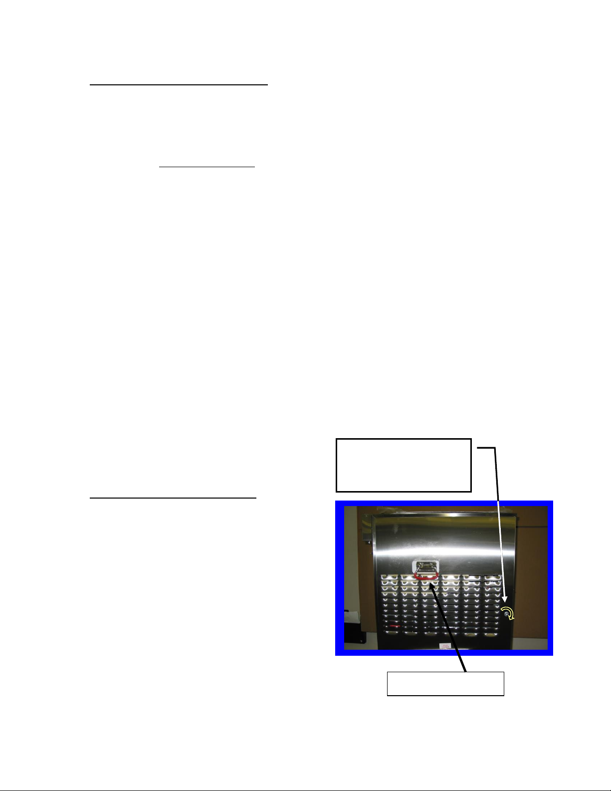
Turning the TCC screw
clockwise will make the
beverage thicker
Note: Optional Handles
The Frozen Drink Machine will produce a fine grain, semi-frozen slush when the proper
mix is used. When measured with a refractometer, the proper mix will measure 13 to 18
“brix”. Too little sugar in the mix will cause larger ice crystals to form. Too much sugar
will lengthen the freeze time.
CAUTION: Freezing water only will cause severe damage to your machine.
NOTICE: Do not add sugar directly into the machine, as some of it will settle and
result in an improper mix.
FRUIT JUICES with at least 32 grams of sugar per 8-oz. serving will freeze well in
the Frozen Drink Machine. They will remain stable during the freezing process while
retaining their natural color and flavor.
NEUTRAL BASES are used to produce a neutral frozen cocktail base. A wide variety
of different drinks can be created from one neutral base by the addition of various flavors.
Most brands of neutral bases specify a mixture of four parts water to one part neutral
base. However, before use in the Frozen Drink Machine, be sure the “brix” level is 13 to
18.
The amount of ALCOHOL in the recipe will affect the freezing process. As a rule of
thumb, for the mix to freeze properly, the recipe should contain no more than 25 percent
alcohol.
Suggestion for optimum production and sales:
1) Use the finest ingredients available.
2) Test the product before serving it.
3) Keep the machine clean - ALWAYS!
3.3 PRODUCT CONSISTENCY
9
3.4 START UP
Never under any circumstances,
place your finger or any other object
into the hopper or feed hole while the
machine is in operation. Serious
personal injury may occur.
When the cylinder is full and the hopper is filled to one inch from the top, the machine is
ready to run. Turn on by selecting the “right” (snowflake) position of both switches on
the front panel.
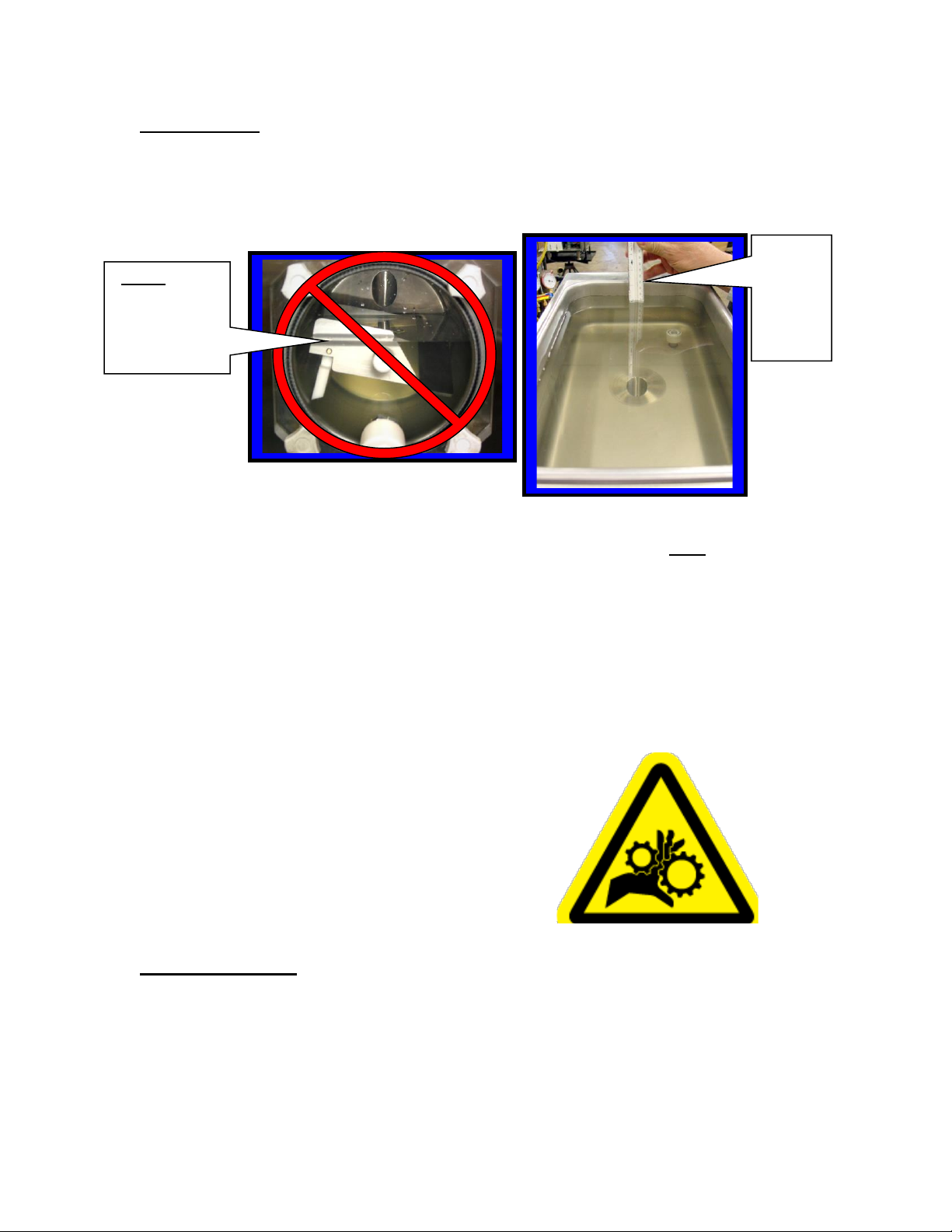
Fill the
Hopper
to about
1 inch
from the
top
Do not run the
machine when
the freezing
cylinder is not
completely full!
NOTICE: Before start-up, be sure the machine has been sanitized in accordance
with procedures set forth in the cleaning section of this manual.
Pour the mix into the hopper and allow it to drain into the cylinder.
NOTICE: Always add mix as soon as the orange, level indicator light, above the
switches, comes on to prevent air from entering the cylinder.
CAUTION: Allowing air into the cylinder will cause a rocking motion of the machine.
If the mix is not yet frozen the air can escape by turning the machine off for
20-30 seconds.
WARNING:
3.5 FREEZE TIME
The freeze time on the Model 127A is approximately 20 minutes when ideal
conditions are met. Such as, pre-cooled starting mix temperature of 40 degrees and
room temperature at 80 degrees. The time will increase if the machine in not properly
ventilated or is operated in a hot environment. Recipes with high alcohol or high
sugar content will naturally take a little longer.
10
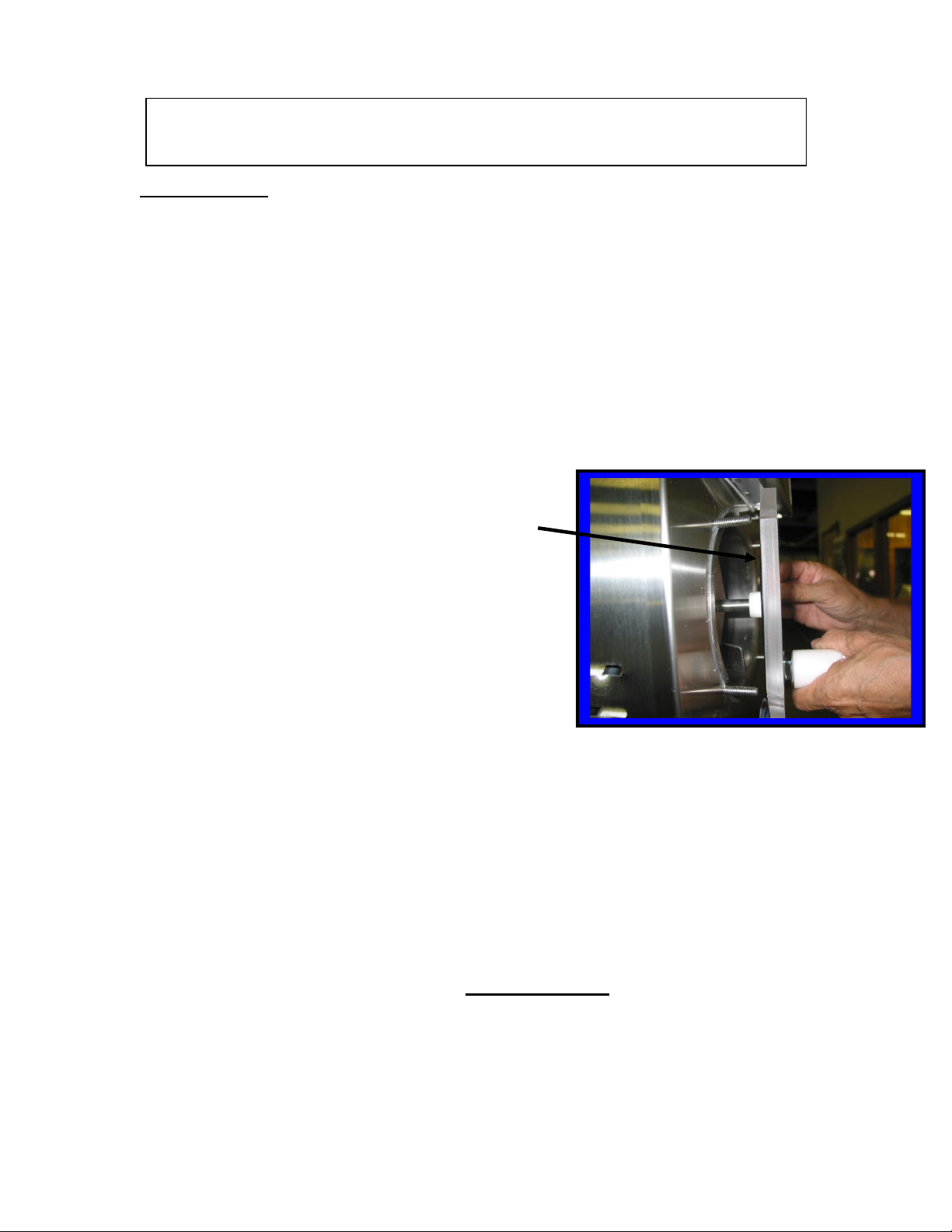
(4) Remove the knobs from the faceplate by turning in
a counter clockwise direction. Carefully pull the
faceplate straight away from the front of the machine.
Remove the beater bar assembly from the cylinder.
Then slide the spring seal off the rear of the beater bar.
Unscrew white faucet cap to remove faucet plunger
from faucet body. Remove all O-rings for cleaning.
4.1 CLEANING
The following cleaning procedure should be used for initial start-up and on an as
needed basis to comply with the minimum cleaning and sanitizing frequencies
specified by the federal, state or local regulatory agency having jurisdiction.
(1.) Turn the machine to the off, “hand” position then remove hopper cover.
(2.) If applicable, drain mix into a sanitized container as per local health code
procedures.
NOTICE: Do not put hands or foreign matter into mix.
(3) Pour two gallons of cool (75ºF.) water into the hopper. Place upper switch in
“faucet” position to let the machine stir for 2 minutes. Turn machine “OFF”, drain
and dispose of the rinse water. Repeat until water is clear.
NOTICE: Do not unscrew faucet body from faceplate
to clean. (Leak free service after disturbing the Teflon
seal cannot be assured).
(5) All parts removed during the above steps plus the drip tray and insert can now be
cleaned in your warm (100º F) cleaning solution. Rinse all parts in clean water and
allow to air-dry before re-assembly.
(6) Use cloth and cleaning solution to wipe any residue from cylinder and hopper.
(7) Re-assemble as shown in section 4.2 (next page).
(8) Mix two gallons of warm water (approximately 100º F) with two ounces of
sanitizing powder to achieve 100 parts/million (PPM) sanitizing solution.
(9) Pour the sanitizing solution into the hopper.
(10) Place upper switch in “faucet” position. Let solution stir for 5 minutes. Turn
upper switch “OFF” (hand) position. Drain all solution.
Notice: Do not leave the solution in the machine for more than 5 minutes.
(11) Pour product into hopper. Replace hopper cover. Place both switches in right
(snowflake) position when ready to freeze product.
SECTION 4
MAINTENANCE
 Loading...