

Page 1

FROSTFROSTFROSTFROST
OIL - FIRED CONSTRUCTION HEATER
MODEL IHS 1500
JULY 2014
TO PRESENT
Installation - Operation
Maintenance Instructions
and Parts List
READ INSTRUCTIONS PRIOR TO STARTING HEATERS
FROST FIGHTER INC.
100-1500 NOTRE DAME
WINNIPEG, MANITOBA
CANADA R3P 0E9
TEL : (204) 775-8252
FAX: (204) 783-6794
TOLL FREE: (888) 792-0374
WWW.FROST-FIGHTER.COM
JULY, 2014
Page 2
FROSTFIGHTER WARRANTY
Frost Fighter Inc. warrants the Frostfighter heater to be free from defects in
workmanship and materials for a period of twelve (12) months from date of initial
service not to exceed fifteen (15) months from date of shipment.
If during the warranty period, the heat exchanger fails under normal use and service
due to a defect in material or workmanship said heat exchanger will be repaired or
replace free of charge F.O.B. the Winnipeg Factory..
All mechanical and electrical components are covered by a one (1) year limited
warranty. Normal maintenance items are excluded under the warranty. The
warranty does NOT include any freight, labor or sales taxes incurred by the
purchaser and is subject to the following conditions:
1. The heater shall be operated in accordance with the manufacturer’s
operating and maintenance manual.
2. The heater shall be subject to normal use in service and shall not have
been misused, neglected, altered or other wise damaged.
3. The unit shall be operated within the rated capacities and with the
prescribed fuel.
4. The unit has not been allowed to exceed its proper temperature limits due
to control malfunction or inadequate air circulation.
5. There is no evidence that the unit has been subject to tampering or
deliberate destruction.
No representative of Frost Fighter Inc., nor any of its distributors or dealers, is
authorized to assume for Frost fighter Inc. any other obligations or liability in
connection with this product, not alter the terms of the warranty in any way. This
warranty is limited to the express provisions contained herein and does not extend to
liability for labor costs incurred in replacing defective parts.
Parts can be obtained from Frost Fighter Inc., Winnipeg, Manitoba on the basis that
credit will be issued if the defective parts returned qualify for replacement pursuant to
the terms and conditions of this warranty. Authorization to return any alleged
defective parts must be first obtained from the factory prior to transporting the part.
The transportation charges for the alleged defective part must be prepaid by the
owner. Frost Fighter Inc. will not accept charges for parts purchased unless the
conditions of this warranty have been satisfied and prior authorization to purchase
the parts has been received from the factory.
100-1500 NOTRE DAME , WINNIPEG, MANITOBA
R3P 0E9, (204) 775-8252, 1-888-792-0374
Page 3
INSTRUCTION MANUAL
INDIRECT FIRED CONSTRUCTION HEATER
HAZARD DEFINITIONS
The following will be used throughout this manual to bring attention to hazards and
their risk factors, or to special information.
Denotes presence of a hazard which, if ignored, will result in severe personalDANGER
injury, death or substantial property damage.
Denotes presence of a hazard, which, if ignored, could result in severeWARNING
personal injury, death or substantial property damage.
CAUTION Denotes presence of a hazard, which, if ignored, could result in minor
personal injury, or property damage.
NOTICE Intended to bring special attention to information, but not related to personal
injury or property damage.
To the owner-
WARNING Installation and adjustment of the burner requires technical knowledge and
the use of combustion test instruments. Do not tamper with the unit or controls. Call your
qualified service technician. Incorrect operation of the burner could result in severe
personal injury, death or substantial property damage.
Have your equipment inspected and adjusted annually by your qualified service technician
to assure continued proper operation.
Never store gasoline or combustible materials near the heating equipment. This could
result in explosion or fire, causing severe personal injury, death or substantial property
damage.
Never burn garbage or refuse in your heating appliance or try to light theWARNING
burner by tossing burning material into the appliance. This could result in severe personal
injury, death or substantial property damage.
Never restrict air openings on the burner or to the room in which the appliance is located.
This could result in fire hazard or flue gas leakage, causing severe personal injury, death
or substantial property damage.
THE INSTALLATION OF THE UNIT SHALL BE IN ACCORDANCE WITH THE REGULATIONS
OF THE AUTHORITIES HAVING JURISDICTION - Refer to CSA Standard B139-1962, Installation
Code for Oil-Burning Equipment for recommended installation practice.
2
Page 4
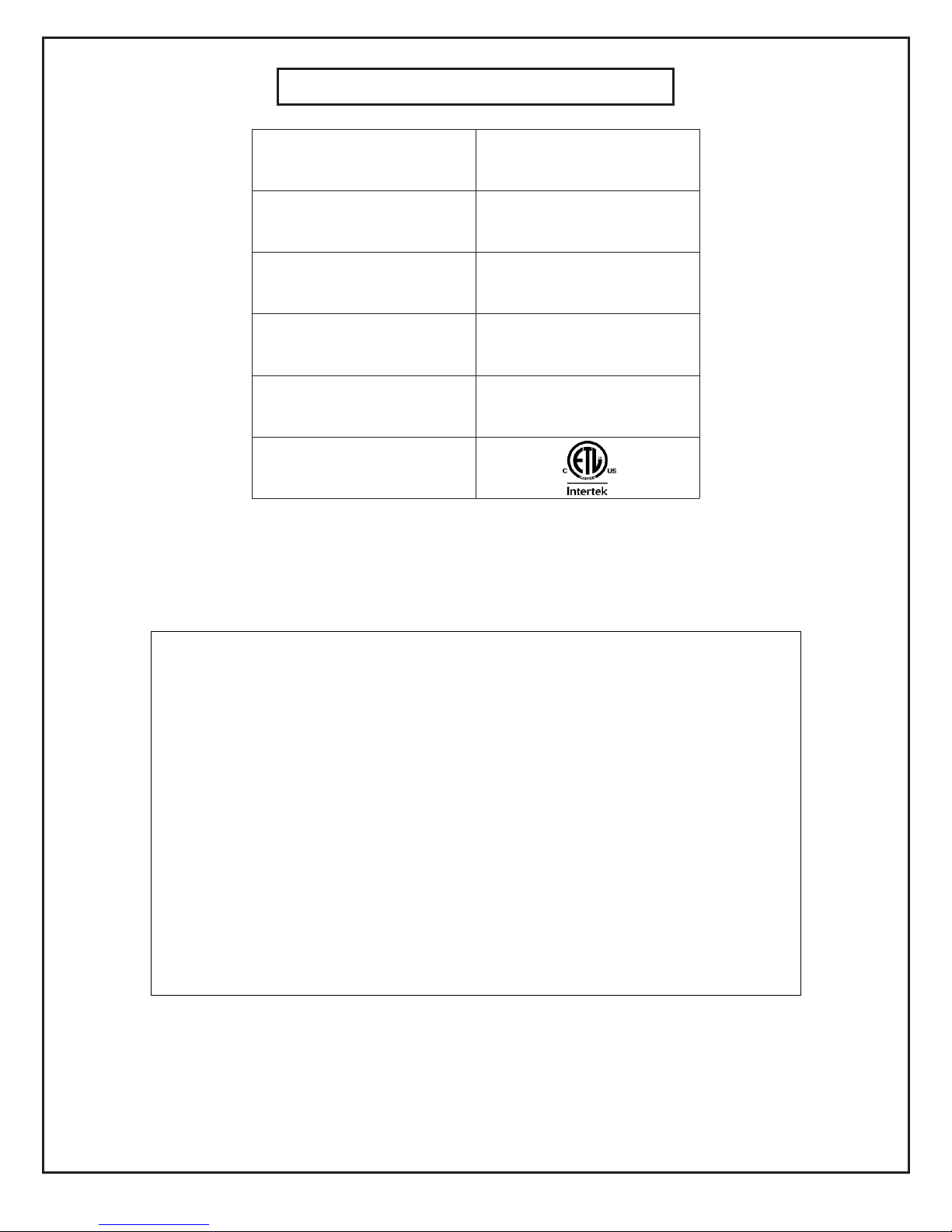
MODEL
IHS-1500
FUEL TYPES
#2 Fuel Oil / Diesel Fuel
NOZZLE
SIZE
6.50 USGPH
45’ B (SOLID)
PUMP
PRESSURE
High Fire 300 P.S.I.g *
Low Fire 140 P.S.I.g *
AIR SETTING
High Fire: 45
Low Fire: 30
Burner Slide Plate Setting: 2
APPROVAL
AGENCY
SPECIFICATIONS
* Pressure at the bleeder port. Subtract 10 PSI if measured at the pump discharge
port. See unit rating plate for exact specifications.
To the owner-
WARNING Read all the instructions before proceeding. Follow all instructions completely.
failure to follow these instructions could result in equipment malfunction, causing severe
personal injury, death or substantial property damage.
This equipment must be installed, adjusted and started only by a qualified service technician
– an Individual or agency, licensed and experienced with all the codes and ordinances, who
is responsible for the installation and adjustment of the equipment. The installation must
comply with all local codes and ordinances and with the National Fire Protection Standard
for Oil-Burning Equipment, NFPA 31 (or CSA B139-04).
NOTICE Concealed damage – If you discover damage to the burner or the controls
during Unpacking, notify the carrier at once and file the appropriate claim.
NOTICE High altitude installations – Accepted industry practice requires no derate of
Burner capacity up to 2000 feet above sea level. For altitudes higher than
2000 Feet, derate burner capacity 4% for each 1000 feet above sea level.
3
Page 5

PRE-INSTALLATION CHECKLIST
COMBUSTION AIR SUPPLY
The burner requires combustion air and ventilation air for reliable operation. Assure that the
Building and/or combustion air openings comply with National Fuel Gas Code NFPA 54/CSA B149. For
appliance/burner units in confined spaces, the room must have an air opening near the top of the room
plus one near the floor, each with a free area at least one square inch per 1000 Btu/hr input of all fuel
burning equipment in the room. For other conditions, refer to NFPA 31 (CSA B1139-M91 in Canada).
If there is a risk of the space being under negative pressure or of exhaust fans or other devices depleting
available air for combustion and ventilation, the appliance/burner should be installed in an isolated room
provided with outside combustion air.
CLEARANCES
The unit must be installed with minimum clearances of 16 inches on the sides, 12 inches from the top of
the unit, 16 inches from the flue (venting), 48” from the front, 0” from the floor, 48” from ductwork and 36
inches from the burner access side. The unit must be installed on a level floor.
DUCT INSTALLATION
- Duct diameter is 20 inches
- Use belt cuff ducting. Slide the cuff overtop of the duct inlet/outlet and tighten with the belt.
- The top two connections are the heated supply air into the building.
- The bottom two duct connections are for cold air or return air into the heater.
- The heater is approved use with or without ducting.
- Maximum duct length is 100 feed per supply opening. If return air ducting is used the length of
the return air duct must be subtracted form the allowable supply ducting length (i.e. if the return
air duct length is 30 feet the maximum supply duct length is reduced to 70 feet).
- Ducts should be rated for 300 F. minimum.
HIGH LIMITS
- The heater is supplied with manual reset high limits located behind marked panels on the left
side of the heater
- The high limit contacts are normally closed and open on the over temperature condition
- If a high limit trips allow the heater to cool down and then reset the high limit by manually
depressing the reset button located in the centre of the high limit.
4
Page 6
VENT SYSTEM
The flue gas venting system must be in good condition and must comply with all the applicable codes.
OUTDOOR INSTALLATIONS:
For outdoor installation, vent cap must be installed and fastened.
INDOOR INSTALLATIONS:
Must be done in accordance to NFPA 54 (or CSA B149) with local authorities having jurisdictions.
1. The flue must be securely attached to the unit with tight joints.
2. The flue must not be sized to have a cross-sectional area less then that of the flue
collar at the unit.
3. Other appliances must not be connected so as to vent through the vent of this unit.
4. Do not use 90-degree tees or elbows greater than 45 degrees.
5. Do not support the weight of the stack on the flue connection of the heating system.
6. The maximum flue gas temperature is 650 F. “A” vent, or single wall steel pipe must
be used.
7. Minimize connecting pipe length and the number of bends by locating the unit as close
to the flue pipe as possible.
8. Maintain clearances between the flue pipe and combustible materials that are
acceptable to the Federal, Provincial and local authorities having jurisdiction.
9. Unit must be connected to a flue having sufficient draft to ensure proper operation of
unit.
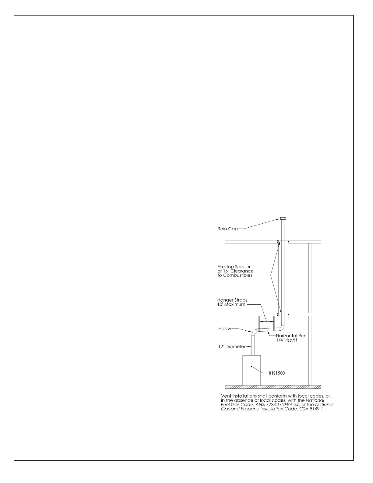
VERTICALLY VENTED UNITS
1. Maximize the height of the vertical run of
vent pipe. A minimum of five (5) feet
(1.5m) of vertical pipe is required. The
top of the vent must extend at least two
(2) feet (0.61m) above highest point on
the roof. A weatherproof vent cap must
be installed to the vent termination.
2. Horizontal runs must not exceed 75% of
the vertical height of the vent pipe, up to
a maximum of ten (10) feet (3m).
Horizontal runs should be pitched upward
¼” per foot
(21 mm) and should be supported at 3
foot (1m) maximum intervals.
3. Design vent pipe to minimize the use of
elbows. Each 90 is equivalent to 5 feet
(1.5m) of straight vent pipe run.
4. Vent pipe should not be run through
unheated spaces. If such runs cannot be
avoided, insulate vent pipe to prevent
condensation inside vent pipe. Insulation
should be a minimum of ½” (12.7mm)
thick foil faced fibreglass, minimum 1 ½#
density.
5. Dampers must not be used in vent piping
runs. Spillage of flue gases into the
occupied space could result.
6. Vent pressure must be negative.
7. The vent must be terminated vertically.
5
Page 7

.
HORIZONTAL FLUE VENTING
25' Maximum
90 Degree elbow
3' Minimum
IHS 1500
Vent installations shall conform with local codes, or,
in the absence of local codes, with the National
Fuel Gas Code, ANSI Z223.1/NFPA 54, or the National
Gas and Propane installation Code, CSA B149.1
3' Minimum
Rise ratio
1/4" per foot
90 Degree elbow
Straight section
Vent Diameter: 12"`
Material: Single wall steel pipe or type A vent
6
Page 8
ELECTRICAL SUPPLY
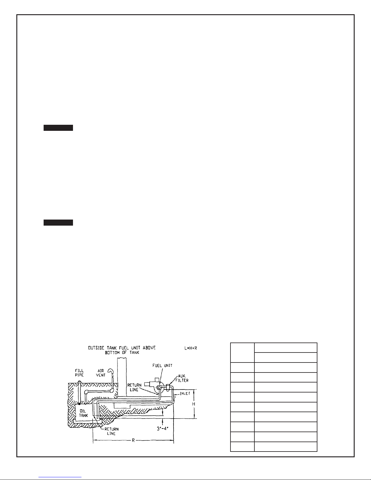
Lift “H”
3450 RPM Motor Speed
3/8” OD Tubing @ 7 GPM
0’
80’2’73’
4’
66’
6’
59’
8’
52’
10’
45’
12’
38’
14’
31’
16’
80’
Verify that the power connections available are correct for the Unit. All power must be supplied
through the disconnect.
INSTALLING THE OPTIONAL THERMOSTAT
Plug the thermostat directly into the receptacle. WARNING: THE RECEPTACLE IS USED FOR
INSTALLING THE THERMOSTAT ONLY! THIS IS NOT A POWER SOURCE.
CONNECT THE FUEL LINE(S) - REFER TO CHART BELOW FOR FUEL LINE LENGTH
WARNING Install the oil lines using the following guidelines. Failure to comply could lead to equipment
damage and present a risk of sever personal injury, death or substantial property damage
due to leakage of oil and potential fire hazard.
Use only flare fittings at joints and connections. Never use compression fittings.
Install fittings only in accessible locations to assure any leak will be detected.
Where joint sealing is needed, use only pipes dope. Never use Teflon tape. Tape strands
can break free and damage the fuel unit.
On two-pipe oil systems verify that the suction line vacuum does not exceed the fuel
manufacturer's recommendation.
WARNING Do not operate the burner unless a return line or a by-pass loop is installed. Failure to
follow this guideline will cause damage to the fuel seals and consequent fuel leakage. This
could result in severe personal injury, death or substantial property damage.
OIL SUPPLY / RETURN LINES
Install the oil tank lines in accordance with all applicable codes.
Use continuous lengths of heavy wall copper tubing, routed under the floor, where possible. Do not attach
fuel lines to the fuel unit or to the floor joists if possible. This reduces vibration and noise transmission
problems.
Install a high quality shut-off valve in an accessible location on the oil supply line. Locate one valve close
to the tank.
TWO-PIPE SYSTEM - (Bypass plug installed in pump) TWO-STAGE TWO-PIPE MAXIMUM
LINE LENGTH (H + R)
7
Page 9
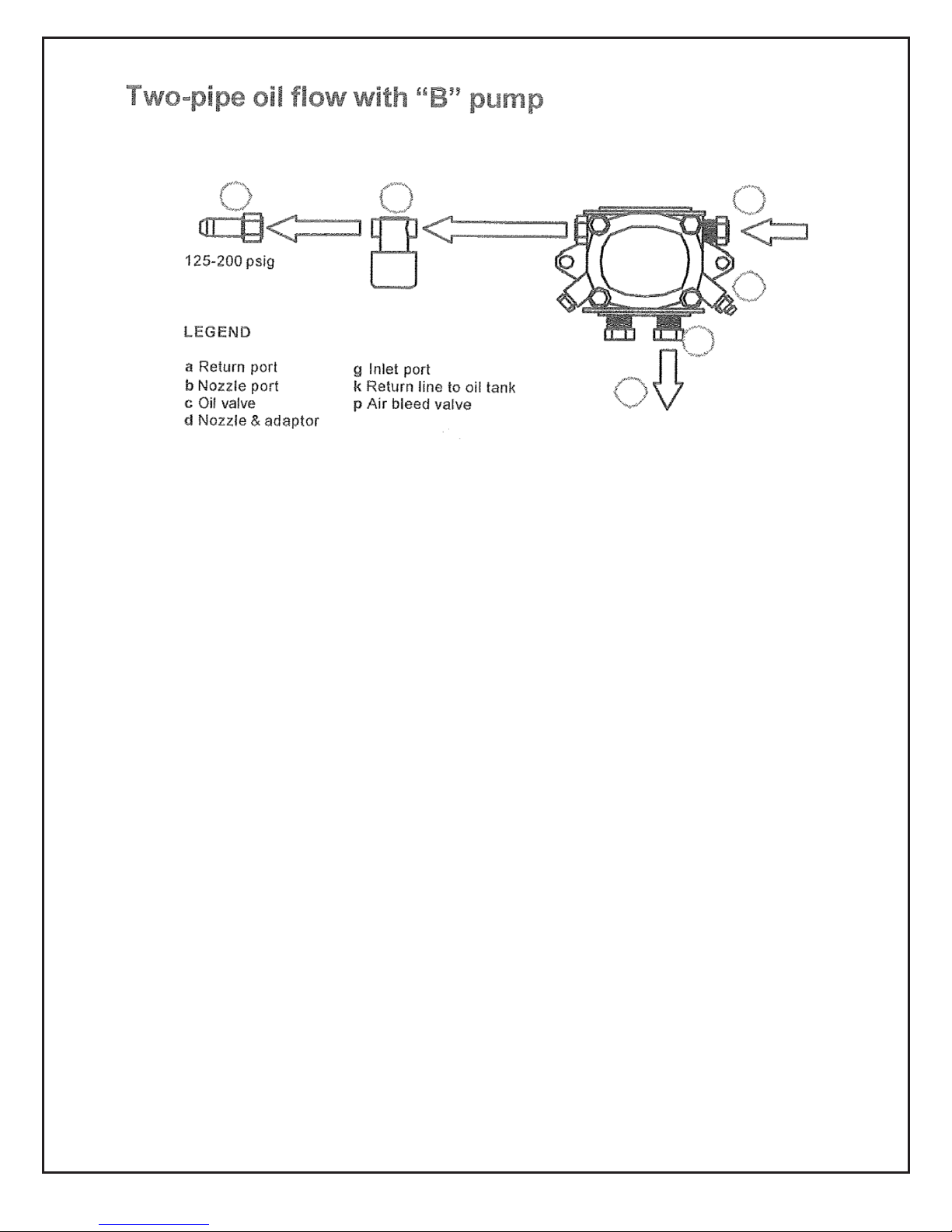
d c
SEQUENCE OF OPERATION – TYPICAL
1. Turn the unit switch to manual.
2. Power is applied to the R7184B black wire (BK).
3. After 10 seconds, the F7184B applies 120 volts to the orange wire (OR),
activating the burner motor (M1) and the ignition transformer (TR). The oil
pump is operated by the burner-motor, so oil pressure is delivered to the oil
valve inlets.
4. Power is applied to the oil valve circuit. After a ten second pre-purge. When
the timer times out, oil valves (S1 and S3) are activated, allowing oil to flow to
the nozzle.
5. Trail for ignition (TFI). A flame should be established within the 15-second
lockout time. If no flame is sensed after 15 seconds, the R7184B will terminate
all power to the blower and oil circuits, shutting the burner down. The control
will electrically lock out and has to be manually reset. If the control locks out
three times in a row, the control enters restricted lockout. Call a qualified
service technician.
6. After the flame is established, there is a 30 second warm-up. After the 30
seconds the main blower starts.
7. When the call for heat signal terminates (at the black wire of the R7184B), the
R7184B terminates power to all circuits, closing the oil valves and stopping the
burner motor. The main blower motor stays in operation for 3 minutes, then the
blower shut down.
140-300 psig
a
k
g
p
(Optional)
If a thermostat is used, the thermostat is plugged into the receptacle on the side of unit. The sensor unit
should be placed in the heated space. On a call for heat the unit will be activated as above.
8
Page 10
PREPARE THE BURNER FOR START-UP
Start-up checklist – Verify the following before attempting to start burner
o Combustion air supply and venting have been inspected and verified to be free of obstruction
and installed in accordance with all applicable codes.
o Fuel connection to nozzle line assembly is secure.
o Fuel supply line is correctly installed, the oil tank is sufficiently filled, and shut-off valves are
open.
START THE BURNER
WARNING Do not proceed unless all prior steps in this manual have been completed. Failure to
comply could result in severe personal injury, death or substantial property damage.
WARNING Do not attempt to start the burner when excess oil has accumulated, when the appliance is
full of vapor or when the combustion chamber is very hot. Do not attempt to re-establish
flame with the burner running if the flames should be extinguished during start-up, venting
or adjustment. Allow the unit to cool off and all vapors to dissipate before attempting
another start. Failure to comply with these guidelines could cause an explosion or fire,
resulting in severe personal injury, death or substantial property damage.
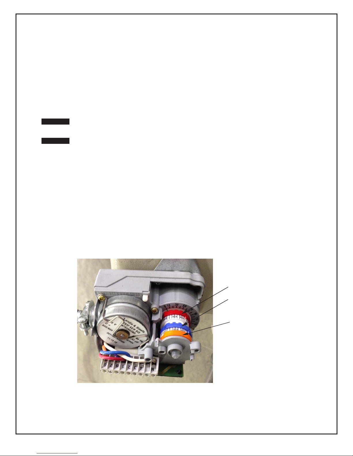
AIR SETTING
The low fire cam should be set at 30 and the
high fire cam at 45. Refer to figure shown below.
In some cases these air-setting needs to be adjusted.
To do this insert your flue gas analyzer into the flue, 6 inches above the top of unit.
Measure you excess O2% and CO2% levels. Set your air shutter to bring your O2% levels
between 5-6%. Your CO2% will be between 9-10% and your CO levels should be around
zero. Alternately, set the burner for #1 smoke spot on the Bacharach scale.
High Fire Cam 45 SetPoint
Low Fire Cam 30 SetPoint
Transition cam set at 35
(Between high and low fire cams)
9
Page 11

DAMPER MOTOR
A
LEGEND
A Cover screw F Damper motor scale
B Cover G Disengaging pin
C Wrench H High fi re cam (red)
D Low fi re cam (blue) J Transition cam (orange)
E Cam notch
INITIAL AIR SETTINGS
If your burner was built for a specific OEM (Original
Equipment Manufacturer) application, the manufacturer
will indicate the initial air settings made at Beckett.
Please verify those settings using the following procedure.
The following steps outline the procedure for initially setting
the damper (these settings may be different from
settings specific to a particular OEM).
Remove the cover screw (A) then the cover (B) and
set aside.
Push in on pin (B) to disengage the motor from the
damper shaft and cam stack. Rotate the damper
shaft by hand to place the adjustment cams in a
position where their adjustment scale can be easily
seen. Release pin (G) to secure the damper shaft
and cam stack to the motor.
Using the wrench (C) supplied with the damper
motor, adjust the blue low fi re cam (D) to the initial
setting listed in Table 4.
Using the same wrench, adjust the red high fi re
cam (H) to the initial settings listed in Table 4.
To adjust the high fi re transition, use a small straight
edge screwdriver. Turn the white adjustment screw
located in the orange transition cam (J) until the
cam indicator is half way between the high and low
settings on the scale.
After setting all the cams, make sure the damper
shaft and cam stack is set between its low fi re
setting and its high fi re setting. (If you don’t it may
not move when it is powered.) Push in pin (G),
move the damper by hand so that notch (E) is
between the low fi re setting and high fi re setting
on scale (F), then release pin (G) to re-engage the
motor. When the motor is powered it will go to its
low fi re setting.
This initial setting should be adequate for starting the
burner at low fi re. Once the burner is in operation,
the air setting will be adjusted for best performance as
discussed later in this manual. Don’t forget to re-install
the cover after all adjustments have been made.
The damper plate is attached
by screws to its shaft, and bears
against a fl at on the shaft for alignment. The shaft is
secured to the damper motor by a sleeve coupling with
two setscrews bearing against the damper shaft and two
more against the motor shaft. The motor shaft has a
fl at matching the one on the damper shaft. The fl ats on
the damper shaft and the motor shaft should be aligned
so that the position indicator in the damper motor reads
accurately. The best way to align the fl ats is to tighten
the set screws that bear against the fl ats on the shafts
fi rst, and then tighten the ones that bear against the
round surface of the shafts afterward.
The test for proper alignment is to disengage the damper
motor from its shaft using the disengaging pin (Item G in
Figure 17) and rotate the damper plate to its full closed
position. The position indicator should point to 0° within
+ 5° tolerance.
10
Page 12

SET “Z” DIMENSION
The air slider (z dimensions) settings should be set at 2 on the drawer assembly, which is located
on the right hand side of the burner.
Replace the rear access door on the burner, making sure that the adjusting plate assembly is seated in
the recessed area in the housing. Loosen acorn nut (item c) and spline nut (item b). Move nozzle line to
the head setting #2 and tighten acorn nut (item c) and spline nut (item b).
SLIDE PLATE SETTINGS
11
Page 13

MAINTENANCE AND SERVICE
WARNING Operation and adjustment of the burner requires technical knowledge and the use of
combustion test instruments. Do not tamper with the burner or controls. Failure to
comply could result in failure or the burner or system, resulting in severe personal injury,
death or substantial property damage.
ANNUAL SERVICE
Have the burner inspected; tested and started at least annually by a qualified service technician. This
annual test/inspection should include at least the following:
o Clean burner and blower wheel (to remove lint and debris).
o Test ignition and combustion and verify air damper settings.
o Test fuel lines and all connections
o Inspect combustion air and vent systems.
o Oil motor (if not permanently lubricated).
MONTHLY MAINTENANCE
o Observe combustion air openings and vent system for integrity. Openings must be clean
and free of obstructions.
o Check the fuel lines and fittings to verify there are no leaks.
o Observe burner ignition and performance to verify smooth operation.
o Shut the system down if you observe abnormal or questionable operation. Call a
qualified service agency for professional inspection and service.
o Grease the main supply blower bearings.
CLEANING THE HEAT EXCHANGER
To clean the secondary of heat exchanger remove the clean out panel located above the burner. This
gives you access to the heat exchanger. Remove the exchanger panel and flue baffles. With a brush
clean out the secondary walls. When re-installing the exchanger panel replace the gasket and re-apply
high temperature silicone rated to 800F. To clean out the main drum, remove the burner and with a brush
clean the sides of the drum. To re-install the burner replace the gasket and insure the burner inserts into
the exchanger 3 ¾ inches. Run the unit at full fire.
12
Page 14
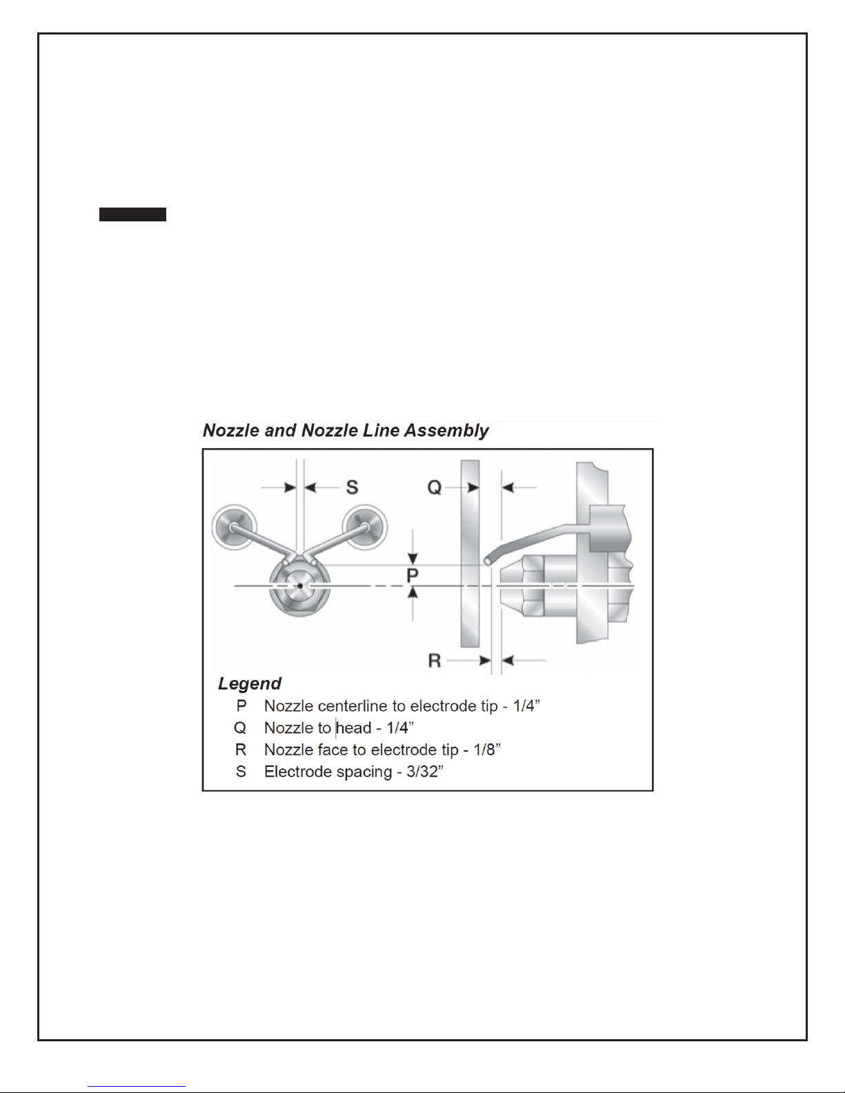
INSTALL NOZZLE
Install the oil nozzle in the nozzle adaptor. Use a ¾” open-end wrench to steady the nozzle adaptor and
use a 5/8” open-end wrench to turn the nozzle. Tighten securely but do not over-tighten.
Verify that the oil tube assembly and electrodes are in good condition, with no cracks or damage.
WARNING Failure to properly set and maintain the electrode and nozzle spacing dimensions can
cause incorrect burner ignition or poor combustion. This could result in severe personal
injury, death or substantial property damage.
13
Page 15

BEARING INSTALLATION AND MAINTENANCE
NOTE: To prevent premature failure – please ensure greasing instructions below are applied. As well,
tighten bearing set screws, collars, and wheel lugs every four to six months.
ENGINEERING – BALL & ROLLER BEARINGS LUBRICATION
For bearings that are equipped with a hydraulic grease fitting threaded into the housing for ease of
lubrication, the proper amount of lubricant in the bearing is important. Both excessive and inadequate
lubrication may cause failure. The bearings should be re-lubricated while they are rotating (if it is safe to
do so); the grease should be pumped in slowly until a slight bead forms around the seals. The bead in
addition to acting as an indicator of adequate re-lubrication provides additional protection against the
entry of foreign matter and helps flush out contaminates in the bearing.
By the time the slight bead is formed, it will be noticed that the bearing temperature will rise. It is not
uncommon for the temperature to rise as much as 30 degrees Fahrenheit after re-lubrication. If
necessary to re-lubricate while the bearing is idle, refer to the recommended re-lubrication grease chart
tables on the following page for various sizes of the bearings.
LUBRICANT-STANDARD BEARINGS:
All bearing units are pre-lubricated at the factory with a lithium soap grease which is compatible with
multi-purpose grease readily available from local suppliers. The lubricant selected for factory lubrication
uses a highly refined mineral oil with a high viscosity index, thickened with lithium soap to conform to
NLGI grade 2 consistency. A suitable additive package is added to protect the highly polished rolling
contact surfaces from corrosion and oxidation of the lubricant. The lubricant is satisfactory for an
operating temperature range of –30 F to +250 F.
Select standard industrial grade greases that conform to the following specification for optimum bearing
performance:
General Duty Ball & Roller;
58-75 SUS @ 210 F
450-750 SUS @ 100 F
Premium Duty Ball & Roller;
68-75 SUS @ 210 F
600-750 SUS @ 100 F
Heavy Duty Roller Bearing;
82 SUS @ 210 F
886 SUS @ 100 F
NOTE: For heavy loaded roller bearing applications, grease with EP additives are often recommended
for optimum performance.
14
Page 16

TABLE I. RECOMMENDED LUBRICATION
Ball Bearings
Roller Bearings
Speed
Temperature
Cleanliness
Greasing Interval
Shaft Size
(inches)
1 – 1 ½ 0.15 1 – ½ to 1 – 1 1/16 0.32
Grease Charge
(ounces)
Shaft Size
(inches)
Grease Charge
(ounces)
Frequency of re-lubrication depends upon operating conditions. The bearing operating temperature is the
best index for determining a re-lubrication schedule. The following chart gives the frequency of re-lubrication
based upon continuous operation for various operating temperatures and can be used as a satisfactory guide
for determining when bearings should be re-lubricated.
TABLE II. LUBRICATION FREQUENCY
100 RPM Up to 120 F Clean 5 months
500 RPM Up to 130 F Clean 2 months
1000 RPM Up to 210 F Clean 2 weeks
1500 RPM Over 150 F Clean Weekly
Any speed Up to 150 F Dirty 1 week to 1 month
Any speed Over 150 F Dirty Daily to 1 week
Any speed Any temperature Very dirty Daily to 1 week
Any speed Any temperature Extreme conditions Daily to 1 week
15
Page 17

TENSIONING V-BELT DRIVES
CLDÜw9 !
FORCE
S
P
A
N
L
E
N
G
T
H
X
PER INCH OF SPAN
DEFLECTION 1/64"
BELT
CROSS
SECTION
(Marked on Belt)
MOTOR PULLEY
PITCH
DIAMETER
DEFLECTION FORCE
1. Ideal tension is the lowest tension at which the belt will not slip under peak load conditions.
2. Check tension frequently during the first 24-48 hours of operation.
3. Over-tensioning shortens the belt and bearing life.
4. Keep belts free from foreign material that may cause slip.
5. Make V-drive inspection on a periodic basis. Tension when slipping. Never apply belt dressing
as this will damage the belt and cause early failure.
Check and tighten belt tension. The following procedure is recommended for tightening belts:
a) Measure span “X” shown in Figure A.
b) At the center of span length “X”, apply a force perpendicular to the span and large enough to deflect
belt 1/64” for each inch of span length. Example- the required deflection for a 40” span would be
40/64” or 5/8”.
c) Compare the force applied with the values given in Table III. If force is between the minimum and
maximum range shown, the drive tension should be satisfactory. A force below the minimum value
indicates an under tightened belt and force that exceeds the maximum value indicates an over
tightened belt.
TABLE III
B 4.4” – 5.6” 4.0 lbs. 5.87 lbs.
MINIMUM MAXIMUM
16
Page 18

SEQUENCE OF OPERATION
1. SYSTEM SWITCH “MANUAL” HEAT SWITCH “LOW FIRE”
After a ninety second purge period, the burner fires on low fire. Thirty seconds after the burner fires the
supply fan starts. when the call for heat from the thermostat is satisfied the burner shuts down and after a
three minute cool down period the supply fan shuts down.
2. SYSTEM SWITCH “MANUAL” HEAT SWITCH “HIGH FIRE”
After a ninety second purge period, the burner fires on high fire. Thirty seconds after the burner fires the
supply fan starts. when the call for heat from the thermostat is satisfied the burner shuts down and after a
three minute cool down period the supply fan shuts down.
3. SYSTEM SWITCH “THERMOSTAT” (the Heat Switch is inoperative in this mode)
On a call for first stage heat from the thermostat, after a ninety second purge period, the burner fires on
low fire. Thirty seconds after the burner fires the supply fan starts. On a call for second stage heat from
the thermostat the burner goes to high fire. When the call for heat from the thermostat is satisfied the
burner and supply fan shut down.
4. SYSTEM SWITCH “OFF”
The heater is inoperative.
NOTES:
- When the “VENTILATION SWITCH” is in the “ON” position the supply fan will run continuously.
- When the system switch is turned off the supply fan will continue to run for three minutes to cool down
the heat exchanger
- Do not shut down the heater by disconnecting the power supply to the heater as this could damage the
heater. To shut down the heater turn the SYSTEM SWITCH to the “OFF” position and wait for the three
minute cool down cycle to complete before disconnecting the power supply.
SEQUENCE OF OPERATION
BECKETT GENISYS 7505
Burner States
1. Standby: The burner is idle, waiting for a call for heat.
2. Valve-on Delay: The igniter and motor are on while the control delays turning on the oil solenoid valve
for the programmed time (45 seconds).
3. Trial for ignition: The oil solenoid valve is energized. A flame should be established within the factory
set trial for ignition time (”lockout time”).
4. Lockout: The control has shut down for one of the following safety reasons:
a. The trial for ignition (lockout) time expired without flame being established
b. The cad cell detected flame at the end of the Valve on Delay state.
To reset the control from lockout click the button 1-second.
NOTE: A recurrence of the above failure modes or a failed welded relay check could cause the control to
enter a Hard Lockout state that must be reset only by a qualified service technician.
To reset from Hard Lockout, hold the reset button for 15 seconds until the yellow light turns on.
5. Ignition Carryover: Once flame is established, the igniter remains on for 10 additional seconds to
ensure flame stability.
6. Run: The flame is sustained until the call for heat is satisfied. The burner is then sent to Motor-Off
Delay, if applicable, or it is shut down and sent to Standby.
7. Recycle: If the flame is lost while the burner is firing, the control shuts down the burner, enters a 60
second recycle delay, and repeats the ignition sequence. The control will continue to Recycle each time
the flame is lost, until it reaches a pre-set time allotment. The control will then go into a Hard Lockout
instead of recycle. This feature prevents excessive accumulation of oil in the appliance firing chamber.
8. Motor-Off Delay: If applicable, the oil solenoid valve is turned off and the control delays turning the
motor off for the set motor-off delay time before the control returns to standby.
9. Pump Prime: The igniter and motor are on with the oil solenoid valve energized for 4 minutes. During
Pump Prime mode, the cad cell is disregarded, allowing the technician to prime the pump without having
to jumper the cad cell.
17
Page 19

RESET BUTTON OPERATION
If the burner is in
the below state:
Pushing the reset
Button Click
(press < 1 second)
Button will:
Button Hold
(press > 1 second)
Button Hold
(press 15+ seconds)
Lockout
Reset from Soft
Lockout
Reset from Soft
Lockout
Reset from Restricted
(Hard) Lockout
Valve-on Delay, Trial
for Ignition Carryover
Run (Ignitor is shut off)
Go to Pump Prime (see
“Priming the Pump”
above)
Yellow light flashes to
indicate cad cell
resistance. See “Cad Cell
Resistance Indicator” for
table of resistance
values.
Disable the Burner:
Any time the burner is
running, press and hold
the reset button to
disable the burner.
The burner will remain off
as long as the button is
held.
Enables Pump Priming:
After the reset button has
been held for 15
seconds, the button can
then be clicked during
the next ignition
sequence to enter Pump
Prime mode.
Motor-off Delay,
Standby
No action
Pump Prime
No action
Exit Pump Prime mode
and return to Standby
Exit Pump Prime mode
and return to Standby
Table 2 explains what action the control will take when the reset button is pressed for different lengths of
time during the various burner operating states.
Priming th Pump
1. Prepare the burner for priming by attaching a clear plastic hose over the bleed port fitting and fully
opening the pump bleed port. Use a suitable container to collect purged oil.
WARNING Hot Gas Puff-Back and Heavy Smoke Hazard
Failure to bleed the pump properly could result in unstable combustion, hot gas puff-back and heavy
smoke.
- Do not allow oil to spray into a hot combustion chamber while bleeding air from the pump.
- Install a gauge in the nozzle discharge port tubing or fully open the pump bleed valve to prevent oil
spray from accumulating in the combustion chamber during the air bleed procedure.
- Ensure that all bubbles and froth are purged from the oil supply system before tightening the pump
bleed valve.
- Ensure that the appliance is free of oil and vapor before starting or resetting the burner.
2. Initiate a call for heat.
3. After the burner starts, press and hold the reset button for 15 seconds until the yellow light turns on.
This indicates that the button has been held long enough.
4. Release the reset button. The yellow light will turn off and the burner will start up again.
5. At burner start up, click the reset button while the igniter is still on. This will transition the control to a
dedicated Pump Prime mode, during which the motor, igniter, and valve are powered for four minutes.
The yellow light will be on.
6. Bleed the pump until all froth and bubbles are purged. If desired, terminate the call for heat or hold the
reset button for at least one second to exit Pump Prime mode and return to Standby.
TABLE 2 - RESET BUTTON OPERATION
18
Page 20
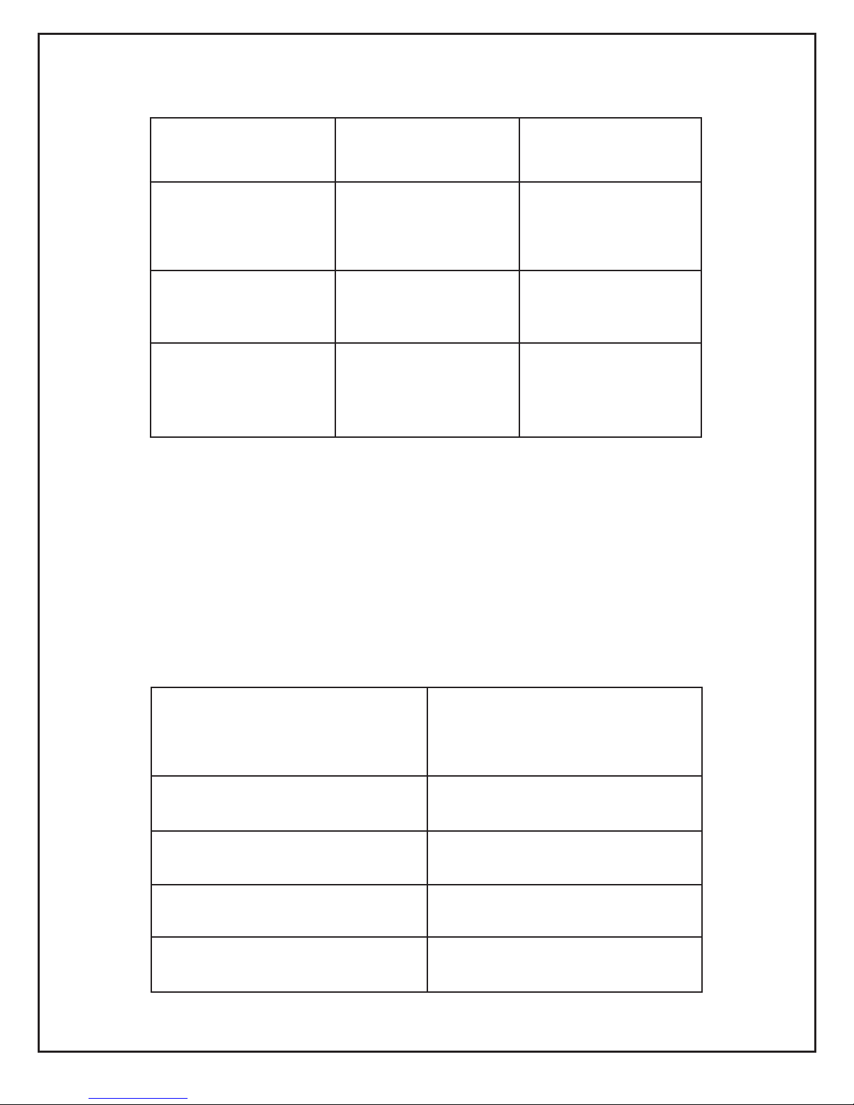
TABLE 3 - STATUS LIGHTS
Light Color
On Continuously
Flashing
Red
Restricted (Hard) Lockout
Soft Lockout
Green
Flame sensed during
normal operation (Could be
stray light during standby)
Recycle
Yellow
Control is in Pump Prime
mode or Reset button
currently held for 15+
seconds.
Cad Cell resistance. See
“Cad Cell Resistance
Indicator” on page 10 for a
table of resistance values.
Yellow
Light
Flashes
Flame Detection Range
1
Normal (0 - 400 ohms)
2
Normal (400 - 800 ohms)
3
Normal (800 - 1600 ohms)
4
Limited (1600 ohms - Lockout)
7. At the end of 4 minutes, the yellow light will turn off and the control will automatically return to standby
mode.
8. If prime is not established during the four minute pump prime mode, return to step 5 to re-enter Pump
Prime mode. Repeat steps 5 through 7 until the pump is fully primed and the oil is free of bubbles.
9. Terminate the call for heat, and the control will resume normal operation.
CAD CELL RESISTANCE INDICATOR
During the burner Run state, click the reset button (less than 1 second) to check the cad cell
resistance range. The yellow light will flash 1 to 4 times, depending on the amount of light
detected by the cad cell. See chart below:
19
Page 21

RESETTING FROM RESTRICTED OR HARD LOCKOUT
WARNING: Fire & Smoke Hazard
Before starting or resetting the control from restricted lockout state, troubleshoot the heating
system for the root cause(s) of the lockout.
1. Make necessary repairs or adjustment to ensure a safe start condition.
2. Ensure that the appliance is free of oil and oil vapours before starting or resetting the burner.
3. If the control continues to lockout without a satisfied call for heat, or fails the motor relay check,
the control enters Hard (restricted) Lockout in order to limit accumulation of unburned oil in the
combustion chamber.
4. To reset, hold the button down for 15 seconds until the red light turns off and the yellow light
turns on.
5. Always verify the control functions according to all specifications before leaving the installation
site.
6. Replace the control if it does not operate as specified.
DISABLE FUNCTION
Any time the burner is running, press and hold the reset button to disable the burner. The burner
will remain off as long as the button is held.
20
Page 22
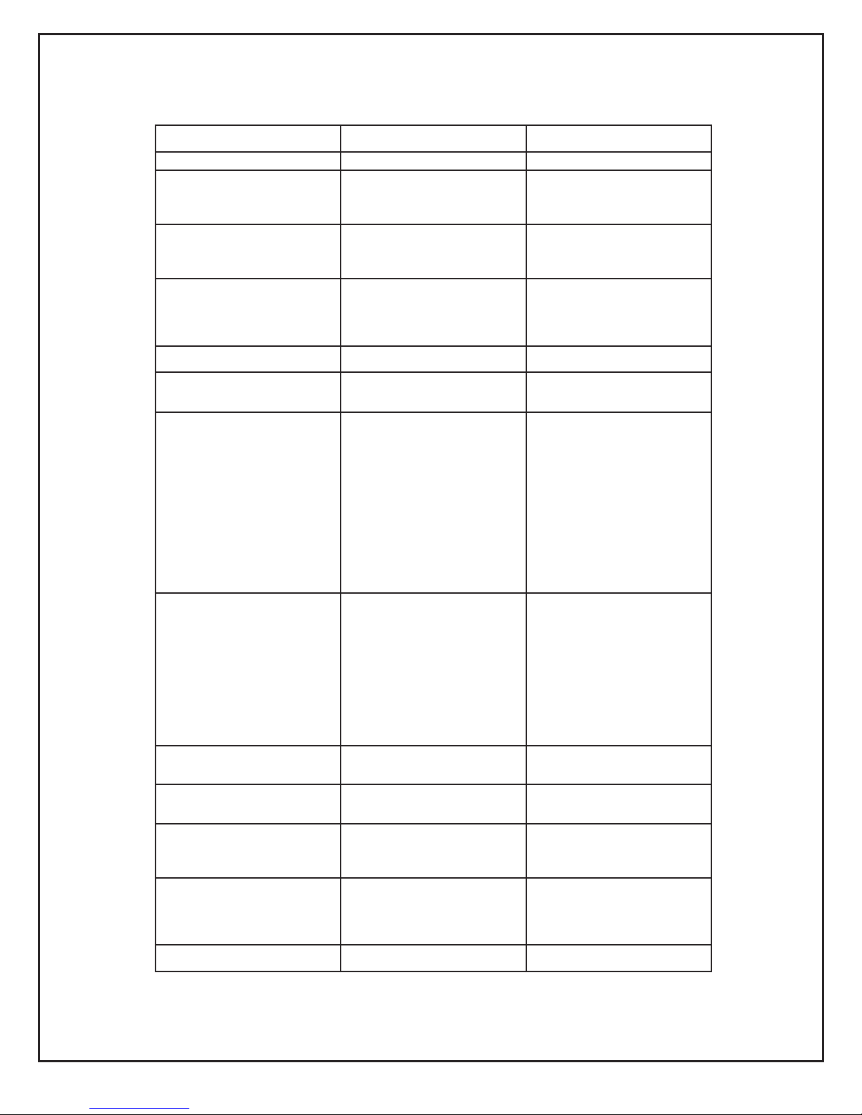
TROUBLE SHOOTING GUIDE
Procedure
Status
Corrective Actions
1. Check that the limit switches
are closed and contacts are
clean.
-
-
2. Check for line voltage power
at the oil primary control.
Voltage should be 120 vac.
-
-
3. Check indicator light with
burner off, no call for heat (no
flame).
Indicator light is on
Cad cell or controller is
defective, sees external light or
connections are short. Go to
step 4.
Indicator light is on
Go to step 5.
4. Shield cad cell from external
light.
Indicator light is off
Eliminate external light source
or permanently shield cad cell.
Indicator light is on
*Replace cad cell with new cad
cell and recheck.
*If indicator light does not turn
off, remove cad cell lead wires
from R7184B and recheck.
*If indicator light turns off,
replace cad cell bracket
assembly. Refer to
TRADELINE® Catalog for
bracket part numbers.
*If indicator light does not turn
off, replace controller.
1. On warm air systems,
jumper thermostat (T to T
terminals on R7184). On
hydronic systems jumper (limit
terminal and L1 of R7184.)
IMPORTANT:
First remove one thermostat
lead.
Burner starts
Burner does not start
Trouble in thermostat or limit
circuit. Check thermostat or
limit wiring connections.
*Disconnect line voltage power
and open line switch.
*Check all wiring connections.
*Tighten any loose
connections and recheck.
*If burner does not start,
replace R7184.
Condition: Burner starts,
and
1. Check that limit switches are
closed and contacts are clean.
-
-
2. Check for line voltage power
at the oil primary control.
Voltage should be 120 Vac.
-
-
3. Check indicator light with
burner off, no call for heat (no
flame).
Indicator light is on
Cad cell or controller is
defective, sees external light or
connections are shorted.
Go to step 4.
Indicator light is off
Go to step 5.
21
Page 23
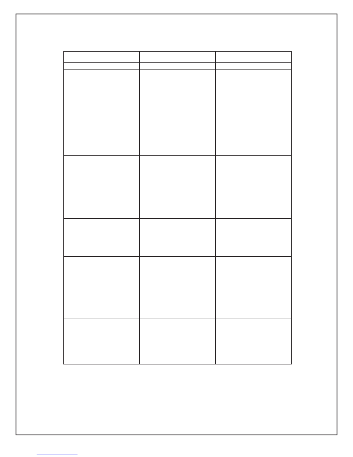
Procedure
Status
Corrective Actions
4. Shield cad cell from external
light.
Indicator light turns off.
Indicator light stays on
Eliminate external light source
or permanently shield cad cell.
*Replace cad cell with new cad
cell and recheck.
*If indicator light does not turn
off, remove cad cell lead wires
from R7184B and recheck.
*If indicator light turns off,
replace cad cell bracket
assembly. Refer to
TRADELINE® Catalog for
bracket part numbers.
*If indicator light does not turn
off, replace controller.
5. On warm air systems,
jumper thermostat (T to T)
terminals on R7184B. (On
hydronic systems, jumper limit
terminal and L1 or R7184B).
IMPORTANT:
First remove one thermostat
lead.
Burner starts
Burner does not start
Trouble is in thermostat or limit
circuit. Check thermostat or
limit wiring connections.
Disconnect line voltage power
and open line switch.
Check all wiring connections.
Tighten any loose connections
and recheck.
If burner does not start,
replace R7184B.
Condition: burner starts
6. Reset oil primary control by
pushing in and releasing red
reset button.
Indicator light stops flashing
Indicator light continues to
flash at 1 Hz rate.
Verify that control is not
restricted mode (see footnote
a). If not in restricted mode,
replace R7184.
7. Listen for spark after burner
turns on (after a 2 second
delay.
Ignition is off
Ignition is on
Ignition is on, but no oil is
being sprayed into the
combustion chamber.
Spark ignitor could be
defective. Check for line
voltage at ignitor terminals. If
line voltage is present, replace
R7184B.
Go to step 8.
Wait for Valve On Delay to
complete (R7184B). Check oil
valve wiring, pump and oil
supply.
8. Check indicator light after
flame is established, but
before oil primary control locks
out.
Indicator light is on until the
control locks out and starts
flashing during lockout.
Indicator light stays off.
Replace R7184B.
Go to step 9.
TROUBLE SHOOTING GUIDE
22
Page 24

Procedure
Status
Corrective Actions
9. Check cad cell sighting for
view of flame.
*Disconnect line voltage power
and open line switch.
*Unplug cad cell and clean cad
*cell face with a soft cloth.
Check *sighting for clear view
of flame. *Place cad cell back
in socket.
*Reconnect line voltage power
and close line switch.
*Start burner.
Burner locks out
Burner keeps running
Go to step 10.
System is okay.
10. Check cad cell.
*Disconnect line voltage power
and open line switch.
*Remove existing cad cell and
replace with new cad cell.
*Disconnect all wires from
thermostat terminals to be sure
there is no call for heat.
*Reconnect line voltage power
and close line switch.
*Expose new cad cell to bright
light, such as a flashlight.
Indicator light is on
Indicator light is off
Place control back on burner.
Go to step 6.
Go to step 11.
11. Check cad cell bracket
assembly.
*Disconnect line voltage power
and open line switch.
*Remove cad cell wires from
quick-connect connectors on
the R7184B and leave control
wires open.
*Apply power to device.
*Place jumper across cad cell
terminals after burner motor
turns on.
Indicator light is on
Indicator light is off
Replace cad cell bracket
assembly. Refer to
TRADELINE® Catalog for
bracket part numbers.
Replace R7184B
TROUBLE SHOOTING GUIDE
23
Page 25
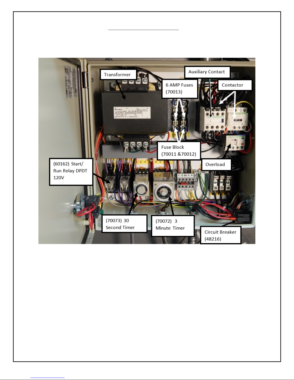
IHS 1500 Wiring Panel
24
Page 26

REPLACEMENT PARTS
25
Page 27

REPLACEMENT PARTS
26
18
19
20
21
Page 28
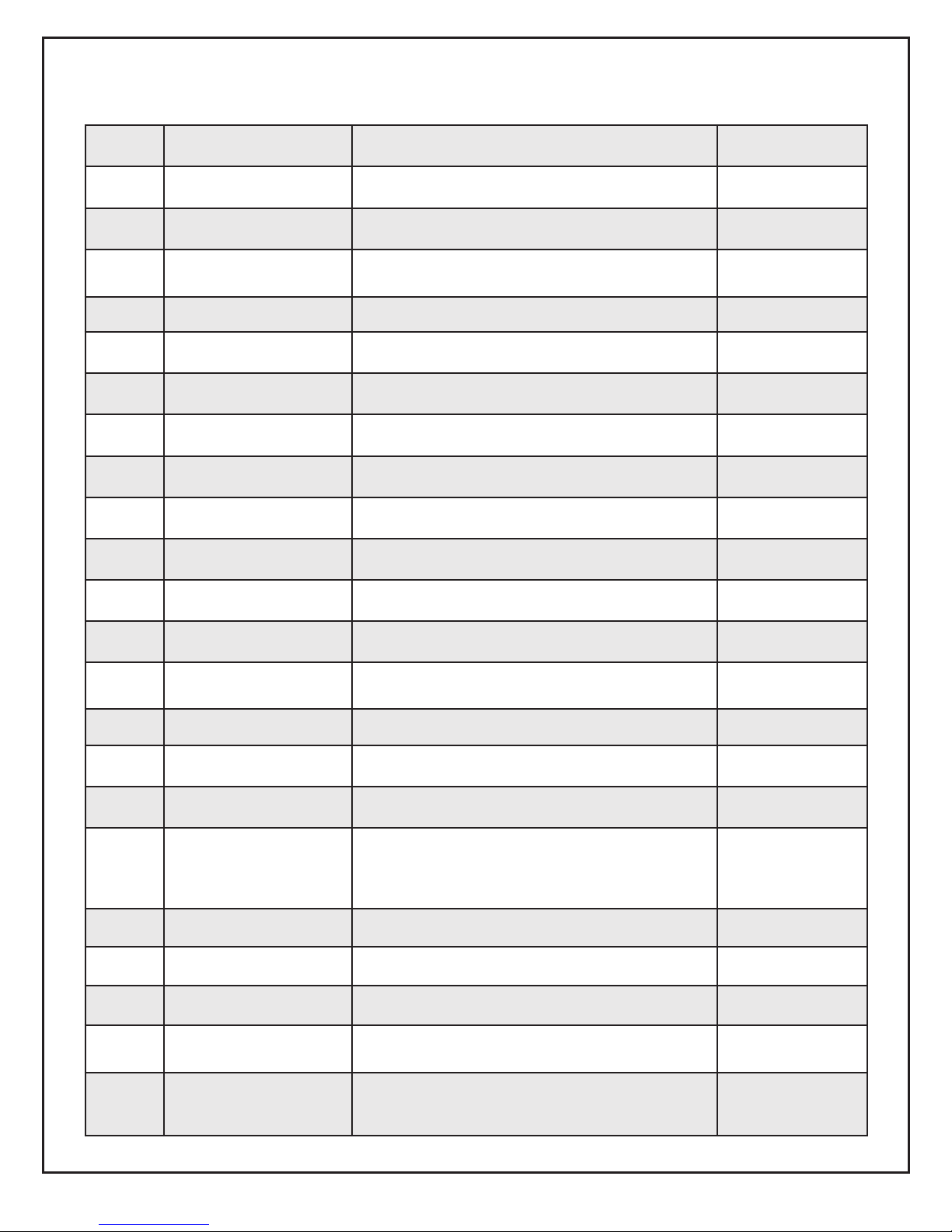
Item
Part Name
Description
Part No.
1
Oil Valve
Mounted on Junction Box
21789U
2
Knurled Nut
All models
3666
3
Adjusting plate assembly
w/ cast aluminum door
w/ stamped sheet-metal door
51213U
5201701U
4
Fuel pump
B2TA-8245
21313U
5
Damper motor
2-stage
750601U
6
Fuel lines
Specify length
-
7
Air Proving Switch
2" W.C.
22181U
8
Timer
Nozzle Valve Delay
21295U
9
Transformer
12,000 volt
51214
10
Control
Specify
-
11
Pedestal kit
All models
51193
12
Coupling hole plug
use with threaded hole
32439U
13
Rear cover door
assembly
w/ cast aluminum door*
w/ stamped sheet-metal door*
51204U
5201302U
14
Sight glass
All models
31346
15
Head assembly
51203
16
Electrode assembly
All models
51212
17
Ignition leads
8-1/4" long
11-3/4" long
15-1/4" long
19-1/4" long
5990082
5990116
5990152
5990192
18
Coupling
B Pump
21549
19
Blower wheel
Cf2300 - 6.75" x 3.13"
21267U
20
Motor Mounting Flange
31347U
21
Motor
120/208-230 single phase
208-230/460 three phase
21402U
21499U
Motor relay (not shown)
120V single phase
208V single phase
Three phase
752804
7300
2194301
REPLACEMENT PARTS
*These doors are NOT interchangeable. Please specify when ordering.
27
Page 29

IHS-1500 OIL WIRING SCHEMATIC (Page 1)
28
Page 30
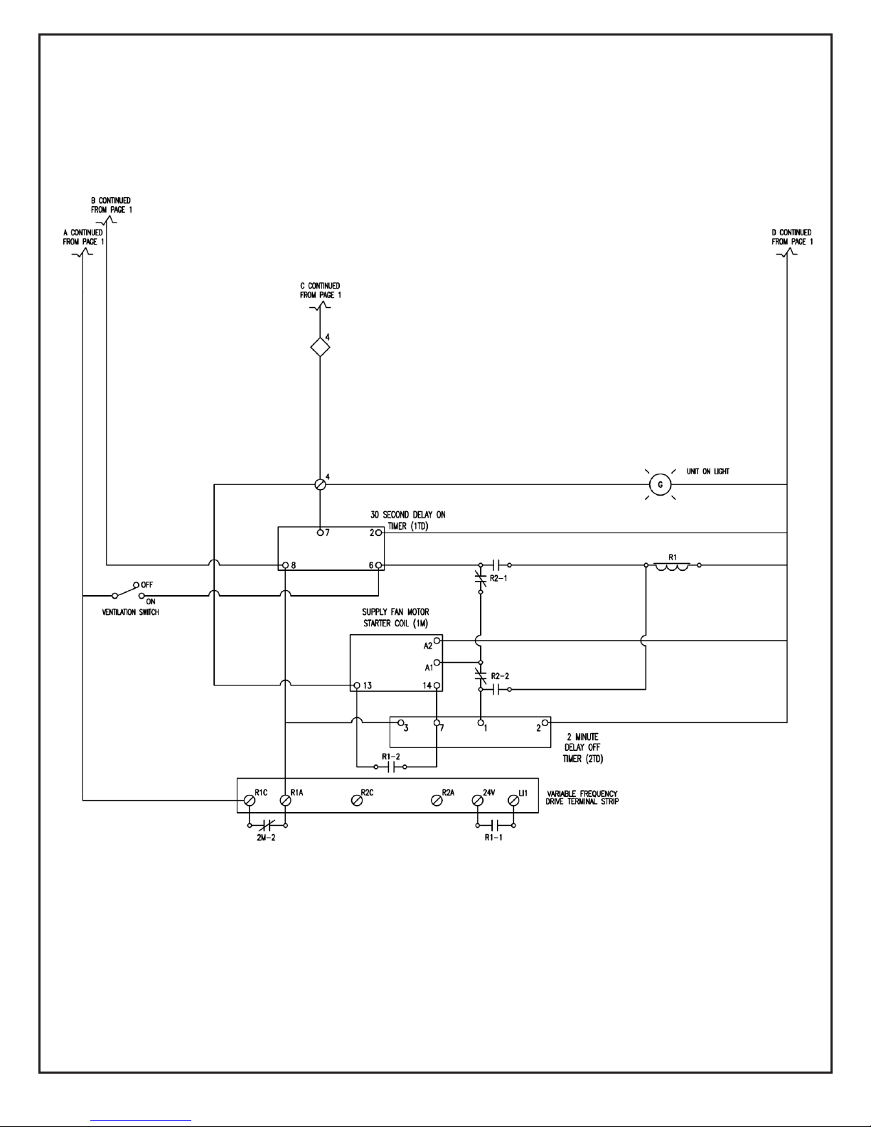
IHS-1500 LPNG WIRING SCHEMATIC (Page 2)
29
 Loading...