

Frost Fighter IDHQR Series, IDH400QR, IDH400QRC Installation - Operation/maintenance Instructions And Parts List

FROST
INDIRECT FIRED SPACE HEATERS
OIL FIRED
MODEL IDH400QR
MODEL IDH400QRC
Installation - Operation/Maintenance
Instructions and Parts List
READ INSTRUCTIONS PRIOR TO STARTING HEATERS
FROST FIGHTER INC.
100-1500 NOTRE DAME AVE
WINNIPEG, MANITOBA
CANADA R3E 0P9
TEL : (204) 775-8252
FAX: (204) 783-6794
WWW.FROST-FIGHTER.COM
TOLL FREE 1-888-792-0374
REV 1.3
JUNE 2018
1
FROSTFIGHTER WARRANTY
Frost Fighter Inc. warrants the Frostfighter heater to be free from defects in workmanship
and materials for a period of twelve (12) months from date of initial service not to exceed
fifteen (15) months from date of shipment.
If during the warranty period, the heat exchanger fails under normal use and service due to a
defect in material or workmanship said heat exchanger will be repaired or replace free of
charge F.O.B. the Winnipeg Factory..
All mechanical and electrical components are covered by a one (1) year limited warranty.
Normal maintenance items are excluded under the warranty. The warranty does NOT
include any freight, labor or sales taxes incurred by the purchaser and is subject to the
following conditions:
1. The heater shall be operated in accordance with the manufacturer’s operating and
maintenance manual.
2. The heater shall be subject to normal use in service and shall not have been
misused, neglected, altered or other wise damaged.
3. The unit shall be operated within the rated capacities and with the prescribed fuel.
4. The unit has not been allowed to exceed its proper temperature limits due to
control malfunction or inadequate air circulation.
5. There is no evidence that the unit has been subject to tampering or deliberate
destruction.
6. The heat exchanger shows no signs of an implosion or explosion.
No representative of Frost Fighter Inc., nor any of its distributors or dealers, is authorized to
assume for Frost Fighter Inc. any other obligations or liability in connection with this product,
nor alter the terms of the warranty in any way. This warranty is limited to the express
provisions contained herein and does not extend to liability for labor costs incurred in
replacing defective parts.
Parts can be obtained from Frost Fighter Inc, Winnipeg, Manitoba on the basis that credit will
be issued if the defective parts returned qualify for replacement pursuant to the terms and
conditions of this warranty. Authorization to return any alleged defective parts must be first
obtained from the factory prior to transporting the part. A R.G.A.# must be provided from an
Frost Fighter Inc representative. The transportation charges for the alleged defective part
must be prepaid by the owner. Frost Fighter Inc. will not accept charges for parts
purchased unless the conditions of this warranty have been satisfied and prior authorization
to purchase the parts has been received from the factory.
100-1500 NOTRE DAME WINNIPEG, MANITOBA
R3E 0P9, (204) 775-8252
2
SPECIFICATIONS
MODEL
MAXIMUM
INPUT
NOZZLE
SIZE
PUMP
PRESSURE
FUEL
TANK CAP.
ELECTRICAL
SUPPLY
HEATED AIR
(W/O DUCT)
APROX.
RUN TIME
IDH400QR
340,000
BTU/HR
2.00 USGPH
45’ B (SOLID)
140 P.S.I.
MAXIMUM
35 IMP GALS.
42 US GALS.
115 VOLT
15 AMP
2850 CFM 2850 CFM
17 HOURS
IDH400QRC
400,000
BTU/HR
2.25 USGPH
45’B (SOLID)
155 P.S.I.
MAXIMUM
35 IMP GALS.
42 US GALS.
115 VOLT
15 AMP
15 HOURS
APPROVAL
AGENCY
DRY
WEIGHT 510 LBS. 510 LBS.
PLEASE REFER TO PAGE 7 IF KEROSENE IS NOT BEING USED.
Flue size-6” on all units
NOTE: -These heaters are intended for use primarily as temporary heating
of buildings under construction, alteration or repair
MAXIMUM ALLOWABLE DUCT LENGTHS
IDH
400
QR
/ IDH400QRC
75
f
ee
t 16" outle
t ducting w/ 0 f
ee
t 16" inle
t ducting
OR
IDH400QR / IDH400QRC 75 feet 2 X 12" outlet ducting w/ 25 feet 16" inlet ducting
50 f
ee
t
2 X 12"
outle
t ducting w/ 50 f
ee
t 16" inle
t ducting
3
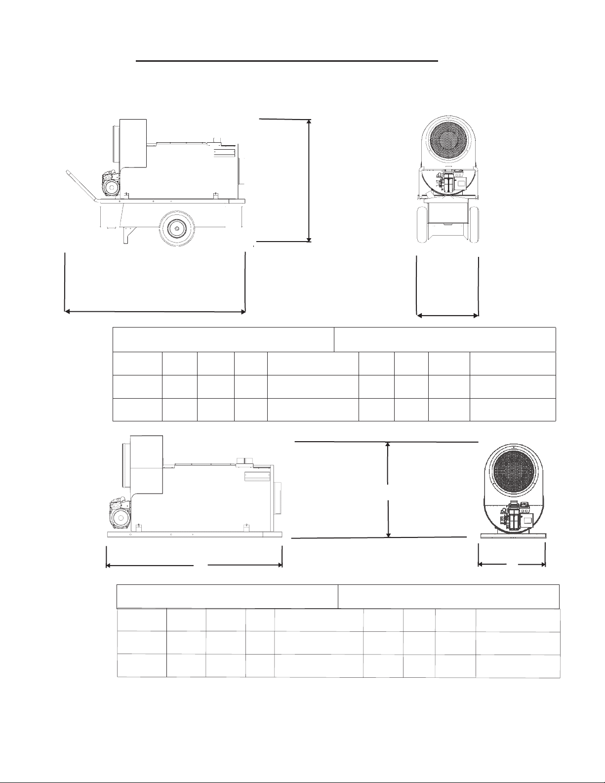
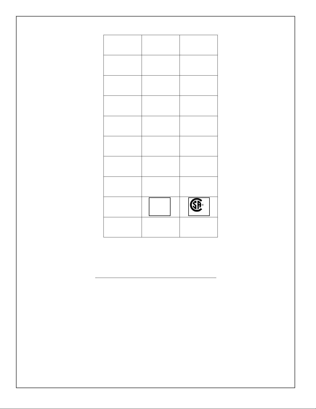
Dimensions of IDHQR series of heaters
A
B
MODEL
IDF350
IDF500
Heater Only
A
51"
51"
B
76 1/2"
76 1/2"
B
C
27"
27"
WEIGHT (LBS)
510
510
L
83"
83"
With Packaging
W
38"
52 1/2"
38"
52 1/2"
A
C
WEIGHT (LBS)
H
562
562
C
MODEL
IDF350
IDF500
Heater Only
A
29 1/2"
29 1/2"
B
65 1/2"
65 1/2"
C
WEIGHT (LBS)
25"
25"
4
325
325
L
70 1/2"
70 1/2"
With Packaging
W
32"
32"
35 1/4"
35 1/4"
WEIGHT (LBS)
H
375
375
INSTALLATION INSTRUCTIONS
1. The recommendations of local authorities having jurisdiction must be followed. For recommended
Installation practices refer to C.S.A. Standard B139 (CANADA) or NFPA 54 (US)
2. When firing the unit in an enclosed area 3 square feet must be provided to allow the free entry of the air
required for operation.
3. For electrical supply, use 3 wire receptacle with “U” ground.
4. Do not operate the unit in partly ventilated areas without a flue pipe or in close proximity to combustible
surfaces or materials.
NOTE: Installation clearances are as follows:
Top - 3 inches
Sides - 24 inches
Burner End -
4 feet
Discharge End - 10 feet Vent
Connector - 24 inches
Floor - Combustible
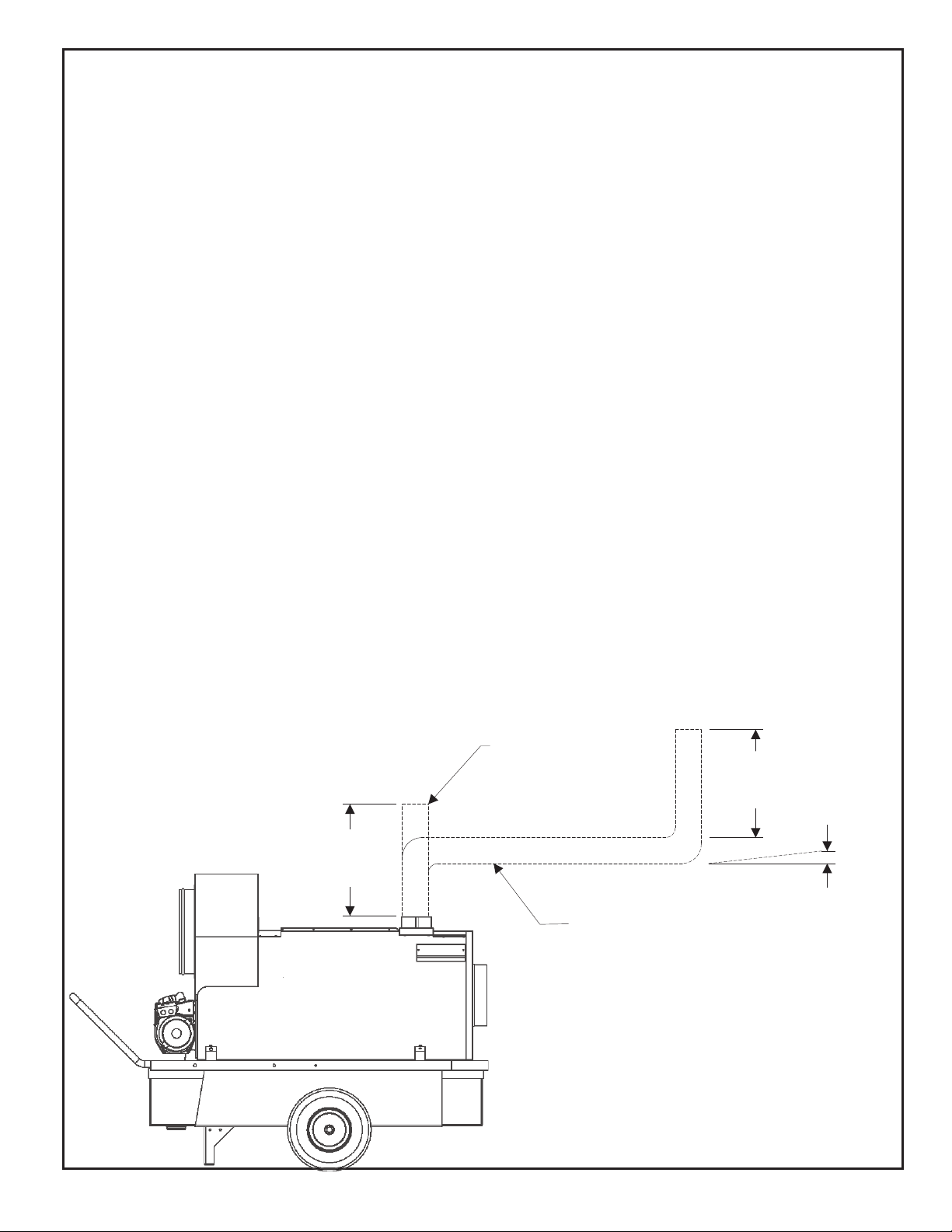
FLUE PIPE CONNECTIONS
When the heater is connected to a flue pipe the flue pipe shall terminate in a vertical
section at least two feet long. Horizontal runs should have rise ratio of 1 in 10 away
from the heater. The chimney should have .02” W.C. draft to ensure safe operation
of the unit. Where down drafts are liable to occur a vent cap should be used. All venting
Should correspond with the CSA B149 (CANADA), NFPA 54 (US) standard or local codes.
INSTALLATION CLEARANCES
FLUE WITH
VERTICAL RUN
2 FT.
MIN.
FLUE WITH
HORIZONTAL RUN
2 FT.
MIN.
RISE RATIO
1 IN 10
5
OPERATING INSTRUCTIONS
TO START HEAT WITH GENISYS CONTROL
1. Ensure unit is on flat, level ground before starting, canopy and fan guards must be closed.
2. Flip switch to “OFF” position
3 Check fuel level ( 2-4 gallons to start)
4. Plug in supply cord to 115 volt outlet.
5. Flip switch to “MANUAL” position.
6. For thermostat operation flip switch to “THERM” position.
7. There will be a 5 second safe start check, a 45 second pre purge then the burner will fire.
IF HEATER FAILS TO START
1. Press manual reset button on burner relay.
2. Check for low voltage condition and 115 volt supply.
3. Check fuel filter, suction tubing and nozzle assembly
NOTE: If unit has been reset a number of times without ignition there will be an
accumulation of oil in the combustion chamber! Do the Following:
1. Make sure unit is sitting on level ground to ensure excess oil drain out of secondary
exchanger (via small drain hole located on outer shell of heat exchanger by burner end).
2. Allow unit to drain for 15-20 minutes or until all oil has drained out.
3. Upon ignition excessive amounts of smoke will be present until all excess
oil has been burnt from the heat exchanger.
4. When the unit has stabilized and the burner set up to operate properly, shut off
the switch. Let the fan cool down the chamber and stop.
IF UNIT STILL DOES NOT START REFER TO THE TROUBLE SHOOTING GUIDE PAGE 13
CAUTION
1. Do not start heater when excess oil has accumulated in chamber.
2. Do not fill tank while unit is operating.
3. Do not shut off by disconnecting supply cord. The heat exchanger
should be properly cooled before power shutdown.
4. In no case should extension cords be smaller than 12 A.W.G. and no
longer than 100 feet.
5. Do not use gasoline, crankcase oil or heavier than No. 2 furnace oil.
6. Always maintain adequate fuel supply.
ELECTRICAL REQUIREMENTS:
15 amp circuit IDH400QR
15 amp circuit IDH400QRC
TO STOP HEATER
Flip switch to “OFF” position. The burner motor will continue to run for 2 minutes to help cool the heat
exchanger and electrodes. The supply fan will continue to operate until the heat exchanger
has sufficiently cooled. Do not disconnect main power until supply fan has stopped running.
WARNING!: BEFORE MOVING ANY GUARDS OR SAFETIES DISCONNECT
THE MAIN POWER AS THE SUPPLY FAN WILL CYCLE
AUTOMATICALLY.
6

IDH MAINTENANCE INSTRUCTIONS
!WARNING!: Heaters should be fully serviced annually to ensure proper
performance. Maintenance should be performed by trained personnel
only. Incorrect maintenance may result in improper operation and
serious injury.
HIGH LIMIT SWITCH
It is recommended that the limit switch should be checked every heating season to ensure the switch
limits the temperature to 250oF (IDH400QR) 290°F (IDH400QRC) (This can be done by restricting the
air
flow through the unit. After tests are complete, remove all restrictions.
FAN SWITCH
The fan switch has been selected to allow for preheating of the heat exchanger to ensure that
only heated air is allowed to enter the space. Upon satisfying the need for heat, the fan switch will
continue to run the supply fan until the heat exchanger has cooled sufficiently. This feature will
help prolong the life of your heat exchanger.
FUEL FILTER
Replace cartridge (48164 or 48164A)once every week of normal usage or sooner, depending
upon fuel quality.
FLAME DETECTOR
To test the cad cell, start the burner and before the safety lock-out timing period ends,
disconnect the cad cell wires from the F-F terminals on the control. Next, jumper the F-F
terminals with a piece of wire. This will allow the burner to continue running so that you will be
able to check the cad cell resistance during the run cycle. If you did not get the F-F terminals
on the control jumpered before the burner locked out, wait 3-5 minutes before attempting this
again. With the burner running, connect the ohmmeter across the cad cell leads. Your signal
should be between 250-1200 ohms. If higher, please clean the cad cell eye or replace.
BURNER
The electrode spacing must be checked and adjusted, if necessary after every nozzle
change. Nozzle should be replaced annually or sooner if burner cannot be set up to
operate properly. Nozzle size and type are marked on the rating plate.
ELECTRICAL
Ensure all conduit (BX) connectors are tight. Check inside connections in control box to ensure
good connections. Check marrettes.
FAN
Check for dust or dirt build up on blades. Check for tightness of the set screw. Run heater to
check for fan vibration. Replace fan blade if vibration is noticeable.
MOTORS
No lubrication is necessary since the bearings are the sealed type. Clean motor of existing dust or dirt.
FUEL SYSTEM
Periodically remove fuel tank drain plug and clean tank. Do not store unit containing
furnace oil for long periods. The quality of fuel oil will affect light off at low ambient
temperatures, #1 fuel oil or kerosene are recommended for temperatures below
-10o C/8oF. (see page 8 for recommended settings if using #2 fuel oil in cold temperature)
FUEL PUMP
Check fuel pump pressure on a regular basis. This can be checked at the bleeder screw.
ADD 10 LBS TO THIS READING TO GET THE TRUE PRESSURE.
There is a pressure loss when fuel passes through solenoid valve. Example: IDH400 pressure
should be read at the port as 150 PSI, then the reading at nozzle line will then be 140.
HEAT EXCHANGER
If a smokey condition continues even after adjusting the air band assembly, the heat exchanger
should be thoroughly cleaned as per next page.
7
CLEANING PROCEDURE
1. Remove front cap. (48205 or 48205A)
2. Remove cover panel (jacket to front). (48119)
3. Remove fan thermostat cover on outer jacket (the one nearest the burner). (48112A)
Loosen thermostat and remove from the jacket. Remove high limit thermostat
cover.(48112). Remove the two screws that are on jacket, at the 3’o’clock & 9 o’clock
position 8 inches from front of unit.
4. Slide heat exchanger out of jacket and place front face down on floor.
5. Access for combustion chamber and heat exchanger cleaning is obtained through
the burner head opening and by removing the heat exchanger cap ring(s) (50115).
6. To reassemble, reverse procedure. If you need assistance, please contact the factory.
Close canopy and ensure fan guards are in proper position before trying to restart the unit..
COMBUSTION AIR ADJUSTMENTS
****For proper combustion air adjustment a calibrated gas analyzer and smoke tester should be
used to ensure complete combustion. Air adjustment should be made at the correct input and be
adjusted to achieve 10% CO2. For optimum combustion efficiency the combustion air control should be
set to provide no more than a No. 1 smoke (Bacharach Scale). The Beckett burner has a calibrated air
band, which will assist in adjusting the primary air for a good oil/air mixture. Adjust air band supply by
loosening lock screws and moving air shutter (B48254) and if necessary the bulk air band. Begin by
reducing the air until the unit begins to produce smoke. Increase air until no smoke is produced. Check for
excessive heat build up in the heat exchanger. Insufficient air will cause flame impingement and reduced
heat exchanger life. Increase air until heat build up has been eliminated. Check for proper ignition. Once
satisfied re- tighten all screws and locking mechanisms.
This adjustment is to be carried out while the unit is operating and after 5 minutes of firing. Rotating the air
bands on the burner housing makes the adjustment.
PRELIMINARY AIR SETTINGS
IDH400QR
IDH400QRC
SHUTTERUNIT MODEL
8
10
BAND
0
0
BURNER MODEL
CF 500
CF 500
***Note: The above settings are approximations based upon clean equipment in proper working
order below 1000 ft. elevation. Combustion air adjustments will vary with location, altitude and
type of fuel used.
Colder ambient conditions may require less air and higher altitudes may require
more air. (ie. Set shutter on IDH400QR to 6 or 7 in very cold conditions to improve light-off. )
Due to the increased density of #2 oil at colder temperatures, kerosene fuel must
be used or the oil nozzle may need to be changed as follows at temperatures
below 8'F/-10'C.
Model
IDH400QR
IDH400QRC
Nozzle (USGPH)
1.75 X 45°B Delevan
2.00 X45°B Delevan
8
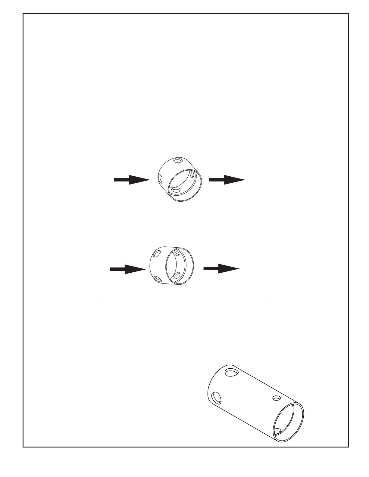
TEMPERATURE FEELER ADJUSTMENT THAT IS ATTACHED TO THE FAN SWITCH
ALWAYS MAKE SURE THAT THE TEMPERATURE FEELER IS TOUCHING THE HEAT EXCHANGER!!
The temperature feeler provides air flow over the fan switch, which regulates the cycling of the fan.
The temperature feeler can be adjusted for different outside temperatures, by rotating the location
of the temperature feeler holes. This will provide optimum performance of the unit in different
applications, and will reduce or eliminate unnecessary fan cycling.
IF SURROUNDING AIR IS WARM (EG., -5 C or 23 F, indoor application):
TURN THE TEMPERATURE FEELER SO THAT THE HOLES ARE PARALLEL WITH THE HEAT
EXCHANGER, AND ENSURE THAT NOTHING IS BLOCKING THE AIR FLOW (EG., SCREWS).
BY DOING THIS THE FAN SWITCH WILL REMAIN COOL AND NOT OVERHEAT. (SEE FOLLOWING)
The fan switch is located under the high limit/fan cover which is mounted on the jacket close to front of unit.
The switch can be adjusted by using a flat-headed screw driver and turning it clockwise or counter clock
wise to desired temperature.
IF SURROUNDING AIR IS COLD (EG., under -5 C or 23 F)
TURN THE TEMPERATURE FEELER SO THAT THE HOLES ARE CLOSED OFF AS THE AIR GOES
OVER THE HEAT EXCHANGER, THIS WILL REDUCE FAN CYCLING, UNIT SHUTDOWN, ETC.
(SEE FOLLOWING)
Indoor and outdoor settings of fan switch
Indoors & if surrounding air is warm i.e. -5C/23F-Fan switch should be set to 115°F or higher
so as to shut down unit when heat exchanger is properly cooled, also keeps fan motor
.
from excessive running on when discharging cooler air.
Outdoor-Fan switch should be set between 100°-90°. The colder the temperature the lower
the setting may need to be to prevent fan cycling.
PLEASE NOTE THAT THERE IS A LONGER
TEMPERATURE FEELER ON THE AUTOMATIC HIGH
LIMIT. THIS SHOULD NOT BE ADJUSTED.
9
 Loading...