

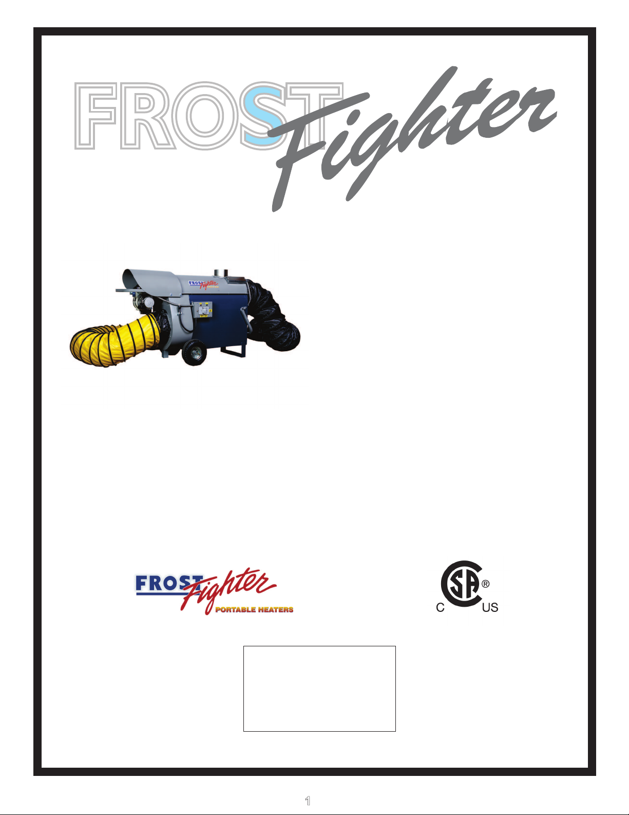
Frost Fighter IDH200QR OIL, IDH200QR LP/NG Installation, Operation & Maintenance Instructions Manual
FROSTFROST
INDIRECT FIRED SPACE HEA
MODEL IDH200QR OIL
MODEL
IDH200QR LP/NG
TERS
Installation - Operation/Maintenance
Instructions and Parts List
READ INSTRUCTIONS PRIOR
TO STARTING HEATERS
FROST FIGHTER INC.
100-1500 NOTRE DAME AVE
WINNIPEG, MANITOBA
CANADA R3E 0P9
TEL : (204) 775-8252
FAX: (204) 783-6794
WWW.FROST-FIGHTER.COM
TOLL FREE 1-888-792-0374
1
VER. 1.3.3
SEPT. 2018
FROSTFIGHTER WARRANTY
Frost Fighter Inc. warrants the Frostfighter heater to be free from defects in workmanship
and materials for a period of twelve (12) months from date of initial service not to exceed
fifteen (15) months from date of shipment.
If during the warranty period, the heat exchanger fails under normal use and service due to a
defect in material or workmanship said heat exchanger will be repaired or replace free of
charge F.O.B. the Winnipeg Factory..
All mechanical and electrical components are covered by a one (1) year limited warranty.
Normal maintenance items are excluded under the warranty. The warranty does NOT
include any freight, labor or sales taxes incurred by the purchaser and is subject to the
following conditions:
1. The heater shall be operated in accordance with the manufacturer’s operating and
maintenance manual.
2. The heater shall be subject to normal use in service and shall not have been
misused, neglected, altered or other wise damaged.
3. The unit shall be operated within the rated capacities and with the prescribed fuel.
4. The unit has not been allowed to exceed its proper temperature limits due to
control malfunction or inadequate air circulation.
5. There is no evidence that the unit has been subject to tampering or deliberate
destruction.
6. The heat exchanger shows no signs of an implosion or explosion.
No representative of , nor any of its distributors or dealers, is authorized toFrost Fighter Inc.
assume for . any other obligations or liability in connection with this product,Frost Fighter Inc
no alter the terms of the warranty in any way. This warranty is limited to the expressr
provisions contained herein and does not extend to liability for labor costs incurred in
replacing defective parts.
Parts can be obtained from , Winnipeg, Manitoba on the basis that credit willFrost Fighter Inc
be issued if the defective parts returned qualify for replacement pursuant to the terms and
conditions of this warranty. Authorization to return any alleged defective parts must be first
obtained from the factory prior to transporting the part. A R.G.A.# must be provided from an
Frost Fighter Inc representative. The transportation charges for the alleged defective part
must be prepaid by the owner. will not accept charges for partsFrost Fighter Inc.
purchased unless the conditions of this warranty have been satisfied and prior authorization
to purchase the parts has been received from the factory.
100-1500 NOTRE DAME WINNIPEG, MANITOBA
R3 , (204) 775-8252E 0P9
2
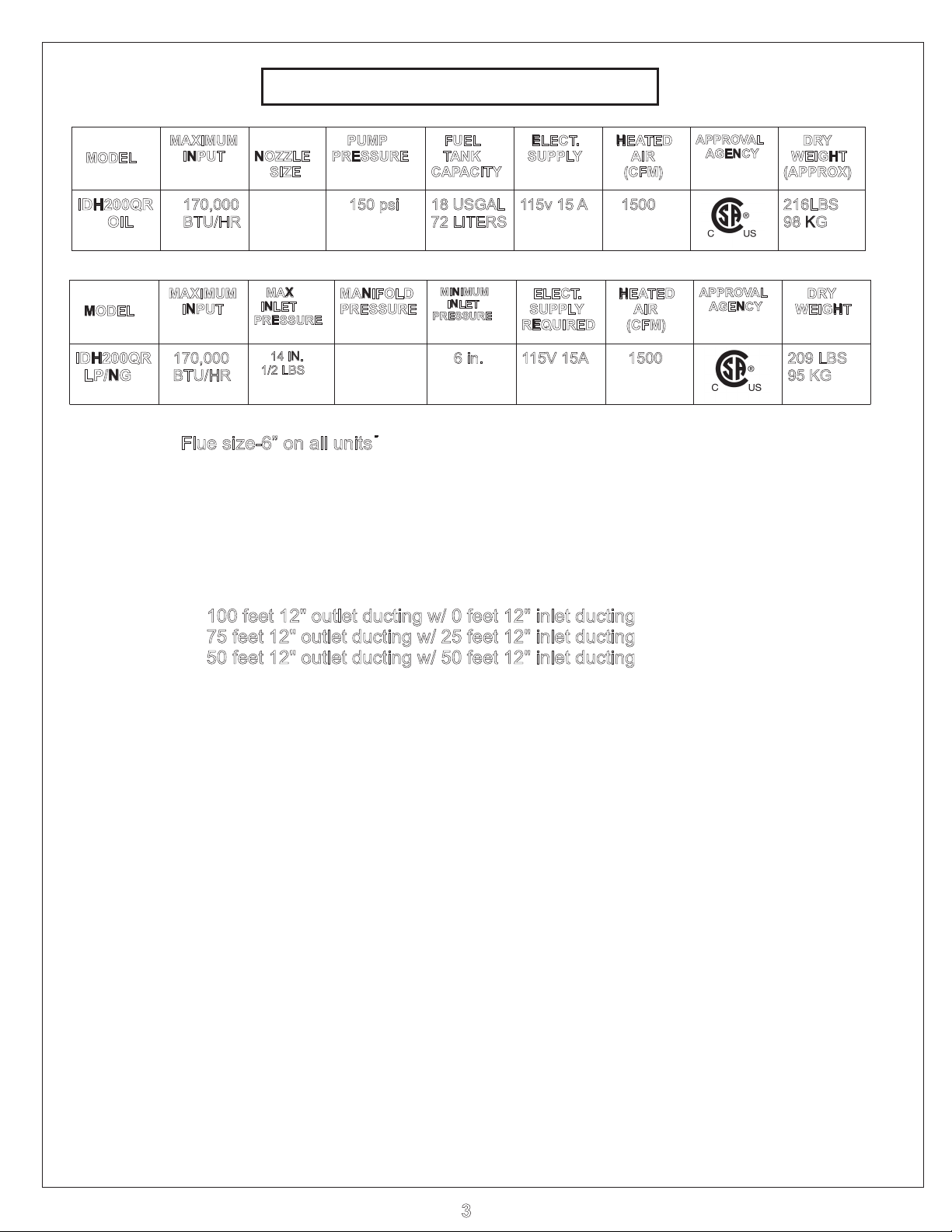
MODEL
MAXIMUM
INPUT
NOZZLE
SIZE
PUMP
PRESSURE
FUEL
TANK
CAPACITY
ELECT.
SUPPLY
HEATED
AIR
(CFM)
APPROVAL
AGENCY
DRY
WEIGHT
(APPROX)
IDH200QR
OIL
150 psi
18 USGAL
72 LITERS
115v 15 A
1500
216LBS
98 KG
MODEL
MAXIMUM
INPUT
MAX
INLET
PRESSURE
MANIFOLD
PRESSURE
MINIMUM
INLET
PRESSURE
ELECT.
SUPPLY
REQUIRED
HEATED
AIR
(CFM)
APPROVAL
AGENCY
DRY
WEIGHT
IDH200QR
LP/NG
0,00017
BTU/HR
14 IN.
1/2 LBS
6 in.
115V 15A
1500
209 LBS
95 KG
SPECIFICATIONS
0,00017
BTU/HR
.85 X 45°A
3.4
" NG
1.9" LP
Flue size-6” on all units
NOTE: -These heaters are intended for use primarily as temporary heating
of buildings under construction, alteration or repair
MAXIMUM ALLOWABLE DUCT LENGTHS ( )IDH200 OIL & LP/NG
100 feet 12" outlet ducting w/ 0 feet 12" inlet ducting
75 feet 12" outlet ducting w/ 25 feet 12" inlet ducting
50 feet 12" outlet ducting w/ 50 feet 12" inlet ducting
RECOMMENDED MANIFOLD GAS PRESSURE
SETTINGS FOR IDH200QR LP/NG MODELS
FOR APPLICATIONS ABOVE 0
Degrees C/32 Degrees F
Set manifold pressure to:
3.4” w.c. NG or 1.9” LP
FOR APPLICATIONS BELOW 0
Degrees C/32 Degrees F
Set manifold pressure to:
3.8” w.c. NG or 2.1” LP
3
POUR LES APPLICATIONS AU-
DESSUS DE 0 °C/32 °F
Régler la pression du collecteur à:
3,4 po GN ou jusqú à 1,9 po LP
POUR LES APPLICATIONS AU-
DESSOUS DE 0 °C/32 °F
Régler la pression du collecteur à:
3,8 po GN ou jusqú à 2,1 po LP
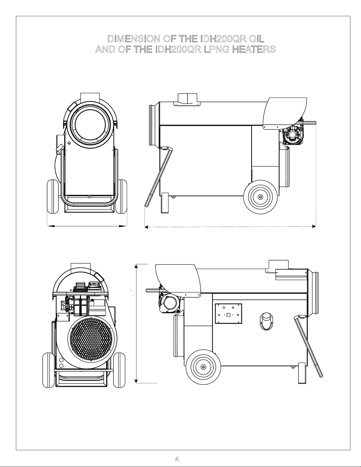
DIMENSION OF THE IDH200QR OIL
AND OF THE IDH200QR LPNG HEATERS
22”
52"
36.5”
4
INSTALLATION- OPERATION
MAINTENANCE INSTRUCTIONS FOR LP/NG
READ INSTRUCTIONS PRIOR TO OPERATING HEATER
GENERAL HAZARD WARNING
FAILURE TO COMPLY WITH PRECAUTIONS AND INSTRUCTIONS PROVIDED WITH
THIS HEATER CAN RESULT IN DEATH, SERIOUS BODILY INJURY AND PROPERTY
LOSS OR DAMAGE FROM HAZARDS OF FIRE, EXPLOSION, BURN, ASPHYXIATION,
CARBON MONOXIDE POISONING, AND/OR ELECTRICAL SHOCK.
ONLY PERSONS WHO CAN UNDERSTAND AND FOLLOW THE INSTRUCTIONS
SHOULD USE OR SERVICE THIS HEATING UNIT.
IF YOU REQUIRE ASSISTANCE OR HEATER INFORMATION SUCH ASAN
INSTRUCTION MANUAL, LABELS, ETC., CONTACT THE MANUFACTURER.
WARNING
FIRE, BURN INHALATION, AND EXPLOSION HAZARD. KEEP SOLID COMBUSTIBLES,
SUCH AS BUILDING MATERIAL, PAPER AND/OR CARDBOARD A SAFE DISTANCE
AWAY FROM THE HEATER AS RECOMMENDED BY THE INSTRUCTIONS. NEVER
USE THE HEATER IN SPACES WHICH MAY CONTAIN VOLATILE OR AIRBORNE
COMBUSTIBLES, OR PRODUCTS SUCH AS GASOLINE, SOLVENTS, PAINT
THINNER, ACETONE, DUST PARTICLES AND/OR UNKNOWN CHEMICALS.
WARNING
THIS PRODUCT IS NOT INTENDED FOR HOME OR RECREATIONAL VEHICLE USE.
FOR YOUR SAFETY
DO NOT USE THIS HEATER IN A SPACE WHERE GASOLINE OR OTHER LIQUIDS
HAVING FLAMMABLE VAPOURS ARE STORED OR USED.
GENERAL NOTES:
NATURAL/PROPANE GAS CODE: B149.1
ALL GAS INSPECTION AUTHORITIES IN CANADA REQUIRE THAT THE
INSTALLATION AND MAINTENANCE OF HEATER AND ACCESSORIES
SHALL BE ACCOMPLISHED BYA QUALIFIED GAS FITTER.
5

GENERAL NOTES:
1. The heater is designed and approved for use as a construction heater under ANSI Z83.7
with the applicable requirements of UL 795 and under CGA 2.14 with applicable
requirements of CAN/CSA 3.2. The intended use is for 5 the temporary heating of building or
structures under construction, alteration or repair.
2. ICE cannot anticipate every use, which may be made of our heaters. CHECK WITH
LOCAL FIRE AND SAFETY AUTHORITY IF YOU HAVE QUESTIONS ABOUT SAFE
APPLICATIONS.
3. Other standards govern the use of fuel gases and heat producing products in specific
applications.
4. Please retain this instruction manual for future reference.
5. The primary application of this heater is for temporary heating of construction sites and/or
applications of this type.
ELECTRICAL NOTES:
1. All electrical connections and grounding shall be in compliance with the National Electrical
Code and/or the Canadian Electrical Code (CSA Standard C22.1-98).
2. W
ARNING: Electrical grounding instructions... This appliance is equipped with a three
prong(grounding) plug for your added protection against electrical shock hazard and should
be plugged directly into a properly grounded three-prong receptacle.
Your local authority can advise you about this issue.
YOUR
ADDITIONAL INSTRUCTIONS FOR PROPANE GAS:
1. Reference the Storage and Handling of Liquefied Petroleum Gas,
National Standards of Canada CAN/CGA B149.2 installation codes for propane gas.
2. The heater must be located more than six (6) feet (1.83 meters) away from the propane
source or propane tank.
3. When the heater is not in use insure to shut o
propane tank.
4. Disconnect the heater from the propane source or propane tank when storing the heater
indoors.
5.
The heater must not discharge toward any propane gas container within 20 feet (6 M).
ff the gas supply from the propane source or
ANSI/NFPA 58 and/or the
6
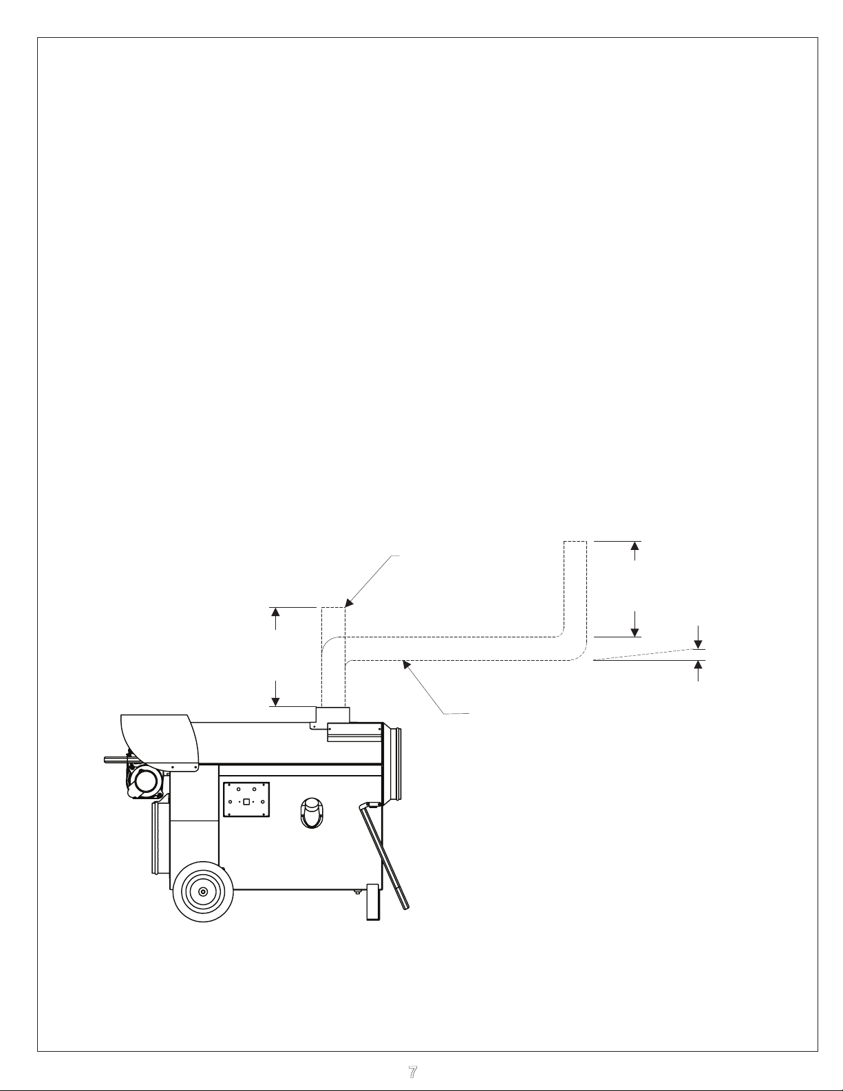
INSTALLATION INSTRUCTIONS
NOTE: Installation clearances are as follows:
Top - Discharge End - 10 feet2 feet
Sides - Vent Connector -2 feet 2 feet
Burner End - 2 feet Floor - Combustible
FLUE PIPE CONNECTIONS
When the heater is connected to a flue pipe the flue pipe shall terminate in a vertical
section at least two feet long. Horizontal runs should have rise ratio of 1 in 10 away
from the heater. The chimney should have .02” W.C. draft to ensure safe operation
of the unit. Where down drafts are liable to occur a vent cap should be used. All venting
Should correspond with the CSA B149 standard or local codes.(CANADA), NFPA 54 (US)
INSTALLATION CLEARANCES
FLUE WITH
VERTICAL RUN
2 FT.
MIN.
FLUE WITH
HORIZONTAL RUN
2 FT.
MIN.
RISE RATIO
1 IN 10
7

INSTALLATION INSTRUCTIONS cont.
LPNG
1. The National Fuel Code, ANSI 223.1/NFPA 54 and/or National Standards of Canada CAN/CGA B149.1
installation codes must be followed as well as the recommendations of local authorities having jurisdiction.
2. Inspect the heater before each use and have it annually inspected by a qualified agency.
3. Inspect the hose assembly for wear
4. When firing the unit in an enclosed area, three square feet (0.278 square meters), must be provided to
allow free entry of the air required for operation.
5. Do not operate the unit in partly ventilated areas without a flue pipe connected to the unit.
6. Do not operate the unit in close proximity to combustible surfaces and materials.
The cylinder supply system must be arranged to provide for vapor withdrawil from the operation
7.
cylinder.
8. Propane tank size should be minimum 100 lbs. (90 liters)
, cuts, etc. and replace if necessary.
OIL
1. The recommendations of local authorities having jurisdiction must be followed. For recommended
Installation practices refer to C.S.A. Standard B139 (CANADA)
2. When firing the unit in an enclosed area 3 square feet must be provided to allow the free entry of the air
required for operation.
or NFPA 54 (US)
3. For electrical supply
4. Do not operate the unit in partly ventilated areas without a flue pipe or in close proximity to combustible
surfaces or materials.
, use 3 wire receptacle with “U” ground.
8

MAINTENANCE INSTRUCTIONS
!WARNING!: Heaters should be fully serviced annually to ensure proper
erformance. Maintenance should be performed by trained personnelp
only. Incorrect maintenance may result in improper operation and
serious injury.
HIGH LIMIT SWITCH
The limit switch should be checked every heating season to ensure the burner will
shutdown if temperature exceeds 220 F. (This can be done by restricting the air
flow through the unit. After tests are complete, remove restriction for proper operation).
AN SWITCH
F
The fan switch has been selected to allow for preheating of the heat exchanger to ensure that
only heated air is allowed to enter the space. Upon satisfying the need for heat, the fan switch will
continue to run the supply fan until the heat exchanger has cooled sufficiently. This feature will
help prolong the life of your heat exchanger.
FUEL FILTER
Replace cartridge every usage or sooner, depending(48164 or 48164A)once week of normal
upon fuel .quality
BURNER
The electrode spacing must be checked and adjusted, if necessary after every nozzle
change. Nozzle should be replaced annually or sooner if burner cannot be set up to
operate properly. Nozzle size and type are marked on the rating plate.
ELECTRICAL
Ensure all conduit (BX) connectors are tight. Check inside connections in control box to ensure
good connections. Check marrettes.
FAN
Check for dust or dirt build up on blades. Run heater to check for fan vibration. Replace fan blade
if vibration is noticeable.
MOTORS
No lubrication is necessary since the bearings are the sealed type Clean motor of existing dust or dirt..
FUEL SYSTEM
Periodically remove fuel tank drain plug and clean tank. Do not store unit containing
furnace oil for long periods. The quality of fuel oil will affect light off at low ambient
temperatures, #1 fuel oil or kerosene are recommended for temperatures below -10
8 F.o(see page 7 for recommended settings if using #2 fuel oil in cold temperature)
FUEL PUMP
Check fuel pump pressure on a regular basis. This should be checked at the bleeder screw.
THE CLEANWITH CUT PUMP ADD 10 LBS TO THIS READING TO GET THE TRUE
PRESSURE. There is a pressure loss when fuel passes through solenoid valve. Example:
IDH200QR oil, 60 Ppressure should be read on the guage at 1 SI, reading at nozzle line will
50then be 1 . Units with the Suntec A2YA7916, pressure reading can be checked at the guage
port. This will provide a true reading.
HEAT EXCHANGER
If a smokey condition continues even after adjusting the air band assembly, the heat exchanger
should be thoroughly cleaned as per next page.
o
o
C /
CLEANING PROCEDURE ON HEAT EXCHANGER
1. Remove 4 bolts securing rear hood (21008) to heater and remove hood.
2. Remove exhaust gas vent trim plate (21206)
3. Remove the high limit cover
4. Remove the push on wires from the limit switch(s) (21006 & 21005 LP/NG) and note their
proper connection location for re-assembly.
5. Loosen the nut securing the connector for the armoured cable where it enters the thermostat
limit switch enclosure and pull entire wiring bundle our from opening in the enclosure end plate.
6. Remove the screws securing top half of the heat exchanger enclosure (21204A) to the bottom
half.
.
9
CLEANING PROCEDURE ON HEAT EXCHANGER cont.
7. Removing the top half of the heat exchanger enclosure will reveal the heat exchanger and the
burner mount tube.
8. Remove the four nuts securing the burner mount tube to the heat exchanger.
9. Heat exchanger can now be slid slightly forward to disengage the studs from the burner mount
tube and will lift out.
10. Clean heat exchanger by using a pressure washer want and hot water inside the opening
where the burner inserts into the heat exchanger and through the flue vent opening to remove
and build up.
1
1.
To reassemble, reverse the procedure. Ensure that the gasket material between the burner
mount tube and the heat exchanger and under the vent trim plate are in good condition when
re-assembling. If gaskets are deteriorated, replace gaskets.
12. Please contact the factory if you need assistance.
Ensure all wiring is re connected to their proper locations and all covers are properly secured
before re starting the unit.
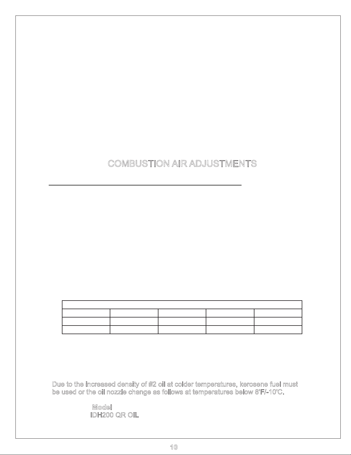
COMBUSTION AIR ADJUSTMENTS
****For proper combustion air adjustment a calibrated gas analyzer and/or smoke tester should be
used to ensure complete combustion. Air adjustment should be made at the correct input and be
adjusted to achieve 10% CO2.
control should be set to provide no more than a No. 1 smoke (Bacharach Scale). The Beckett burner has a
calibrated air band and air shutter, which will assist in adjusting the primary air for a good oil/air mixture.
Adjust shutter by loosening lock screws and moving air shutter (B20254) to the setting listed below. Check
for excessive heat build up in the heat exchanger and any visible smoke from the vent stack V. ery cold
operating conditions may require a slight reduction in air to aid ignition. Insufficient air will cause flame
impingement and reduced heat exchanger life. Increase air until heat build up has been eliminated. Check
for proper ignition. Once satisfied re- tighten all screws and locking mechanisms.
For optimum combustion efficiency on oil models the combustion air
This adjustment is to be carried out while the unit is operating and after 5 minutes of firing. Rotating the air
bands on the burner housing makes the adjustment.
PRELIMNARY AIR SETTINGS
UNIT MODEL SHUTTER BAND SLIDE PLATE BURNER MODEL
IDH200QR OIL 6 1 2 AFG
IDH200LPNGQR 9 0 n/a
CG4
***Note: The above settings are approximations based upon clean equipment in proper working order.
Combustion air adjustments will vary with location, altitude, air temperature and type of fuel
used. Colder ambient conditions may require less air while altitude increases will require more air.
ADJUST AIR AS NECESSARY TO OBTAIN CLEAN COMBUSTION AND CONSISTANT LIGHTOFF
- Use Combustion Analyzer or Smoke Tester -
Due to the increased density of #2 oil at colder temperatures, kerosene fuel must
be used or the oil nozzle change as follows at temperatures below 8'F/-10'C.
Model
IDH200 QR OIL
Nozzle (USGPH)
0.85 GPH x 45° A Delevan
10

OIL - OPERATING INSTRUCTIONS
T
O START HEAT WITH GENISYS OIL CONTROL
1. Ensure unit is on flat, level ground before starting, canopy and fan guards must be closed.
2.
3 Check fuel level ( 2-4 gallons to start)
4.
5. Flip switch to “MANUAL” position.
6. For thermostat operation flip switch to “THERM” position.
7 There will be a 5 second safe start check, a second pre purge then the burner will fire.. 15
IF HEATER FAILS TO START
1. Press manual reset button on burner relay.
2. Check for low voltage condition and 115 volt supply.
3. Check fuel filter suction tubing, and nozzle assembly
NOTE: If unit has been reset a number of times without ignition there will be an
1. Make sure unit is sitting on level ground to ensure excess oil drain out of secondary
2. Allow unit to drain for 15-20 minutes or until all oil has drained out.
3. Upon ignition excessive amounts of smoke will be present until all excess
4. When the unit has stabilized and the burner set up to operate properly, shut off
Flip switch to “OFF” position
Plug in supply cord to 115 volt outlet.
accumulation of oil in the combustion chamber! Do the Following:
exchanger by burner end(via small drain hole located on outer shell of heat exchanger ).
il has been burnt from the heat exchanger.o
the switch. Let the fan cool down the chamber and stop.
IF UNIT STILL DOES NOT START REFER TO THE TROUBLE SHOOTING GUIDE PAGE 13
CAUTION
1.
2. Do not fill tank while unit is operating.
3. Do not shut off by disconnecting supply cord. The heat exchanger
4. In no case should extension cords be smaller than 12 A.W.G. If cord
5. Do not use gasoline, crankcase oil or heavier than No. 2 furnace oil.
6. Always maintain adequate fuel supply.
ELECTRICAL REQUIREMENTS:
TO STOP HEATER
Flip switch to “OFF” position.
exchanger and electrodes.
cooled. Do not disconnect main power until supply fan has stopped running.
Do not start heater when excess oil has accumulated in chamber.
should be properly cooled before power shutdown.
is longer than 50’ use 10 A.W.G. minimum.
15 amp circuit IDH200QR MODELS
The burner motor will continue to run for approx. 1 minute to help cool the heat
The supply fan will continue to operate until the heat exchange has sufficiently
WARNING!: BEFORE MOVING ANY GUARDS OR SAFETIES DISCONNECT
POWER AS THE SUPPLY FAN WILL CYCLETHE MAIN
AUTOMATICALLY.
11
 Loading...