

Page 1

Page 2
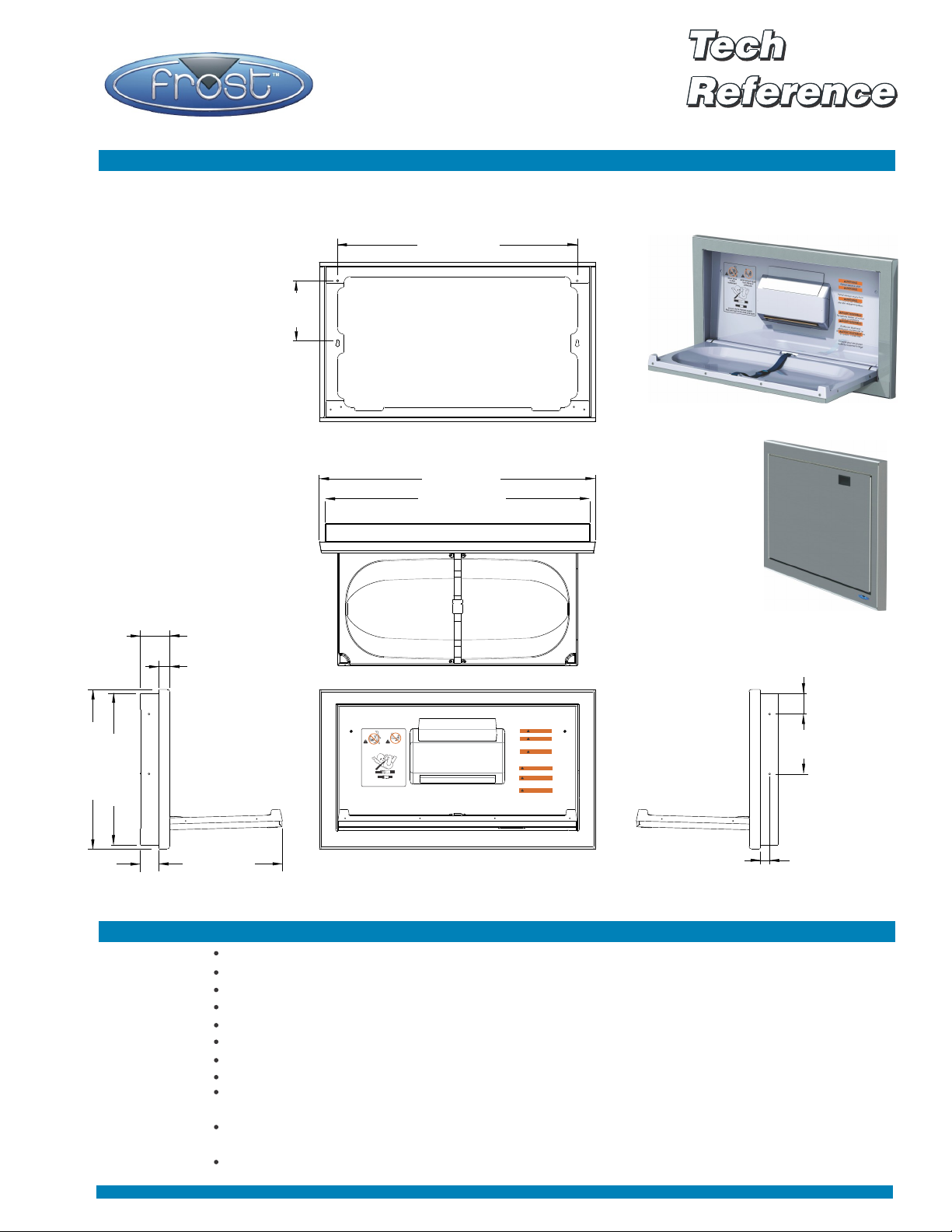
Stainless Steel Baby Change Table
Code 1124-S:
Overall dimensions in inches (centimetres in brackets)
Baby Change Table, Stainless Steel.
32.00 (81.3)
8.00
(20.3)
Surface Mounting Hole Locations
36.90 (93.7)
35.312 (89.7)
Provide 35.625" (90.4) rough opening
Code 1124-S
21.29 (54.1)
20.25 (51.4)
Provide 20.50" (52) rough opening
2.45
(6.2)
Specifications
Site Location:
Features:
Installation:
3.94 (10)
1.48 (3.8)
WARNING
Never leave a child unattended.
WARNING
Avoid serious injury from falling
Avoid serious injury
Never leave
from falling or
a child
sliding out.
unattended.
Always use the restraint system.
Keep one hand on the child at all times.
or sliding out. Always use the
restraint system.
WARNING
Designed for Infants Only. Age
up to 3.5 years and weighing less
than 50 lbs. (23 kg). Keep one
hand on the child at all times.
AVERTISSEMENT
Ne jamais laisser un enfant sans
surveillance.
AVERTISSEMENT
Evitez les blessures sérieuses causées
par le glissement. Toujours ultiliser le
system d’attaches.
AVERTISSEMENT
Conçue pour les jeunes enfants
seulement d'âge jusqu'à 3.5 ans et
pesant moins de 23 kg. (50lbs.). Gardez
une main sur l'enfant en tout temps.
16.54 (42)
Front View
Recessed Mounting
Hole Locations
Ideal for areas where other stainless steel accessories have been specified.
For use with ages up to 3.5 years and weighing less than 50 lbs. (23 kg).
All stainless steel exterior.
Antimicrobial plastic cradle, as well as recessed panel and towel dispenser.
Safety restraint. Clear instructions in French and English.
Smooth action opening and self closing.
Recess and surface mountable.
Dispenses standard multi-fold towels.
Heavy duty, solid non “flexing” in open position. The code 1124-S with its all steel chassis
construction can withstand a static distributed load of 400 pounds.
ASTM guidelines require the change table to be used with infants weighing a maximum of
50 lbs. (23 kg). The Frost Code 1124-S meets ASTM F2285 specifications.
See installation instructions for rough opening and mounting height.
(7)
2.75
8.00
(20.3)
1.27 (3.2)
Page 3
Instructions
Table of contents
Page 1 Operational use and care instructions
Page 2 Overview
Page 3 Recess mounting
Page 4 Surface mounting, mounting hole locations
READ ALL INSTRUCTIONS BEFORE THE ASSEMBLY
AND MOUNTING OF THE DIAPER CHANGING STATION.
Operation:
Pulling on the handle rotate door downward. Place the infant on top of
the changing surface and use belt restraining system, see instructions
below.
WARNING! AVOID SERIOUS INJURY FROM FALLING OR SLIDING
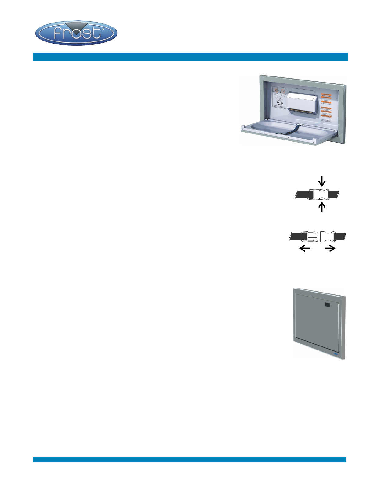
Use of belt restraint system:
If buckle is closed press on the area in mid buckle as shown on left to
open and unlatch the buckle. Place child so restraint strap is located at
the abdomen area. Relatch strap. Adjust strap if required to insure that it
is snug against infant.
WARNING! NEVER LEAVE CHILD UNATTENDED.
After the child has been changed, remove the restraining belt and rotate
door back up against the wall.
WARNING! The unit is rated for 50 pounds (22.7 kg). The addition of
items such as parcels or accessories to the unit or to the bag hooks must
not exceed the total weight limit of 50 pounds (22.7 kg). Failure to do so
may cause the unit to be unstable or create a hazardous condition to the
end users.
Maintenance and cleaning:
1) Check for missing or damaged components on a monthly basis or as
required depending on traffic flow. All hardware and the unit's fitting to
the wall should be tight.
2) Take the unit out of service if any component is vandalized, missing or
damaged. Contact your authorized dealer to order replacement parts.
Do not substitute parts.
3) Apply a mild soap or multi-purpose cleaner (non abrasive) by means
of a damp cloth. Do not allow liquids to pool or soak in any areas of
the changing station. Strong chemical cleaners or cleaning agents
may be hazardous to children, do not use these strong cleaners.
4) Upon delivery check for damage from shipping or handling to job site.
WARNING! Do not install a damaged unit!
OUT. ALWAYS USE RESTRAINT SYSTEM.
Press inwards
Pull apart to unlock
Page 4
Code 1124-S Installation Instructions
This document covers the recessed and surface mounting of the
Code 1124-S stainless steel baby changing station.
Note:
Follow the “ in the installation instructions. Failure to do WARNING!”
so may result in serious injury or death. Read all instructions before
installing the baby changing station. Keep these instructions for
future use.
READ ALL INSTRUCTIONS BEFORE THE ASSEMBLY AND
MOUNTING OF THE DIAPER CHANGING STATION.
Unpack carton and identify the following parts.
PART Type: Quantity:
3” x 1/4” wood screw Phillips head 4
1-1/2” x 1/4” wood screw Phillips head 2
10-24 x 1/2" machine screw Phillips head 2
Tools required: Level
Measuring tape
Power drill
3/16” taper length drill bit (5-3/4" long)
Phillips driver bit for power drill
Phillips screw driver
Overview
WARNING! MUST BE INSTALLED BY A QUALIFIED TRADES PERSON.
WARNING! The diaper changing station is no stronger than the walls to which they are attached and
therefore the unit MUST be firmly secured in order to support the weight it is intended to carry. Contact
the building contractor or Architect if there are any questions.
WARNING! The unit is rated for 50 pounds (22.7 kg). The addition of items such as parcels or
accessories to the unit or to the bag hooks must not exceed the total weight limit of 50 pounds (22.7 kg).
Failure to do so may cause the unit to be unstable or create a hazardous condition to the end users.
Clean up: After the installation is completed remove and dispose of all protective plastic from the
surface of the product. Also dispose of all bags and loose clear tape. Save this instruction sheet for
future reference. Please save the foam and carton in case of product return.
Product Return: Call Frost Products Ltd. customer service (1.905.332.5700) to receive a
Return Authorization Number. Product returns will only be accepted in the original packaging
with the original foam padding. Do not include the hardware in the product return carton.
Registration: To register your product, email the information listed below to
our dedicated email address: [email protected]
Please provide the following in your email:
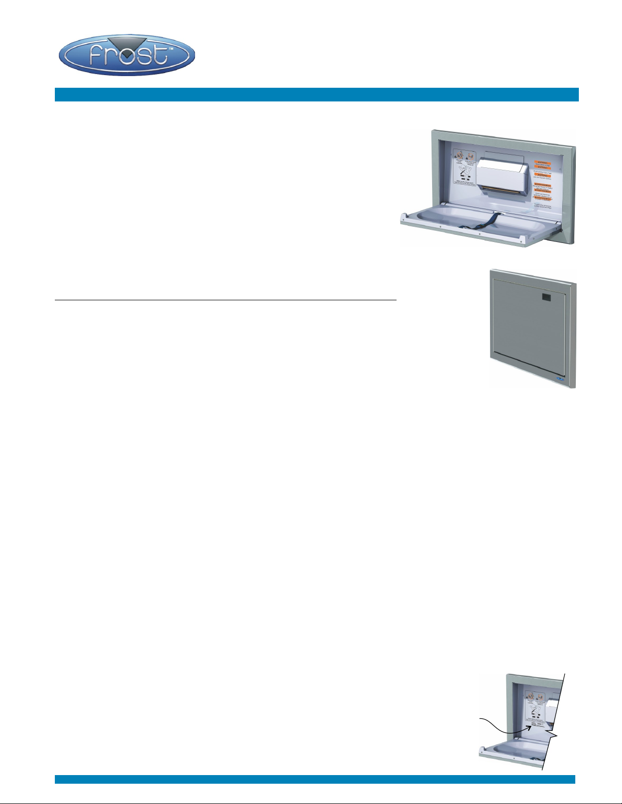
1) Your organization’s contact name, phone number and email adress
Product
info.
2) The Model Number
3) The Batch/W.O.# See illustration on right for location of product info.
Page 5
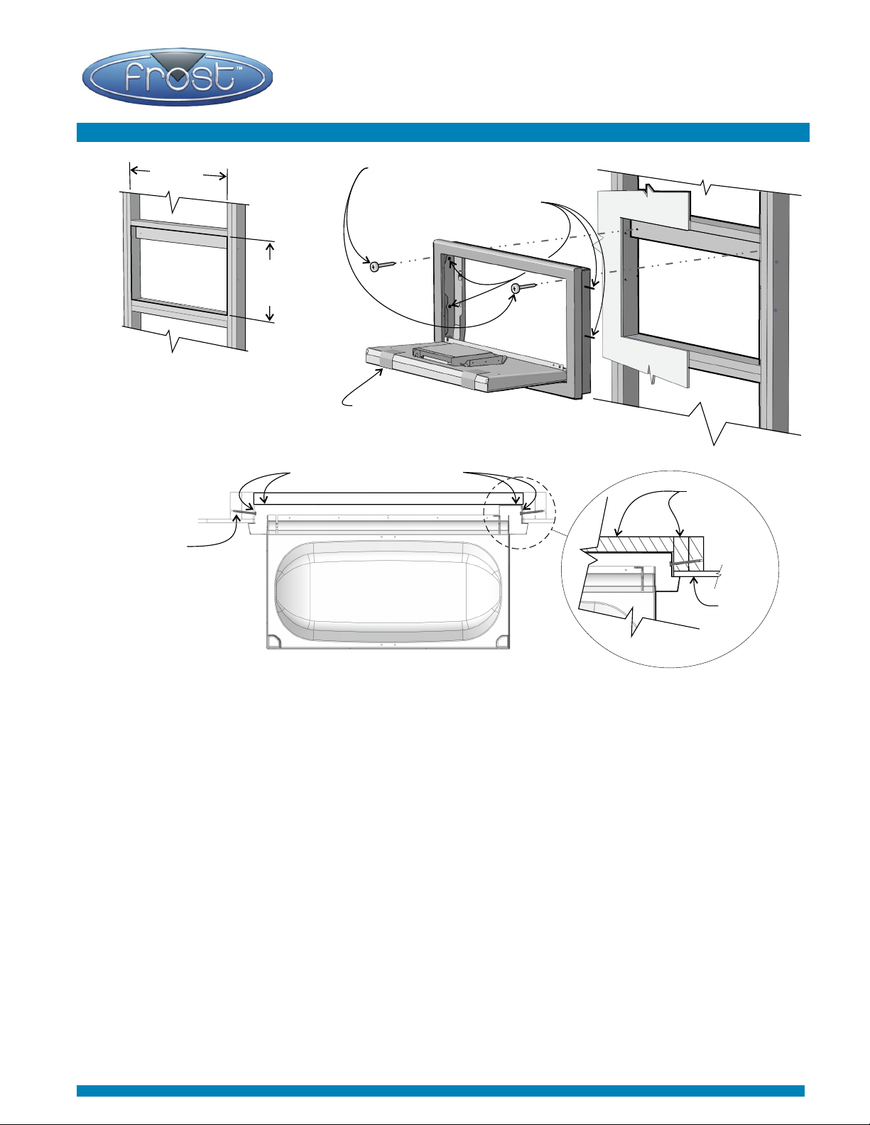
Recess Mounting
35.625"
(90.4)
20.50"
(52)
Rough opening configuration.
double studding, lower top cross
stud flipped on it’s side flush with
back. Results in 2.5" (63.5mm)
depth with 1/2" drywall.
Figure 1
Drill pilot holes
at a 5-10
degree angle.
Two rear mounting screws 1-1/2" long.
Four side screws, 3" long.
Door and recessed panel
remain taped together.
Figure 2
Areas that may require shim.
Studs
Drywall
Top View, Section at mounting screws
Figure 3
Recommended Rough Opening Configuration:
Wood double stud framing is necessary in the rough opening (Fig. 1). Contact an architect and building
official to make sure the framing is adequate and complies with building codes. A.D.A. compliance
guidelines require the top of the lower part of rough opening to be a maximum of 29” (73.7) and a minimum
of 25” (83.5) from floor.
1. Test unit in the rough opening for fit. Shim as required (Fig. 3) to minimise play. Insure the bottom of the
rough opening is level.
2. Slide changer into rough opening. Let it rest on the bottom of the rough opening (this has been made
level in step 1). Flip down door. Door and recessed panel remain taped together during installation, see
Figure 2 above. Using the unit as a template drill six (6) 3/16” pilot holes into the studs. Drill side holes
at a 5-10 degree angle (Figure. 3). Use a 3/6" taper length drill bit (5-3/4" long). Quick Tip: To insure the
unit is snugly pressed against the wall it may require an additional person to help hold the changer in
position while you are drilling the holes and insert the first mounting screw. A total of four side mounting
and two back mounting screws are used (Figure. 2).
3. Insert side wood screws using the power drill with the Phillips driver. Wood screws have been provided
and it is the installer's responsibility to provide correct fasteners for other substrates. Shim the rear
mounting area after the four (4) side screws have been installed. Insert the last two (2) rear screws.
4. Ensure all six (6) screws are tight. Do not over tighten to the point of distortion.
5. Remove tape and flip up recessed panel to Insert two (2) 1/2" long Phillips machine screws to secure
recessed panel to complete the installation, see Figure B next page.
Page 6
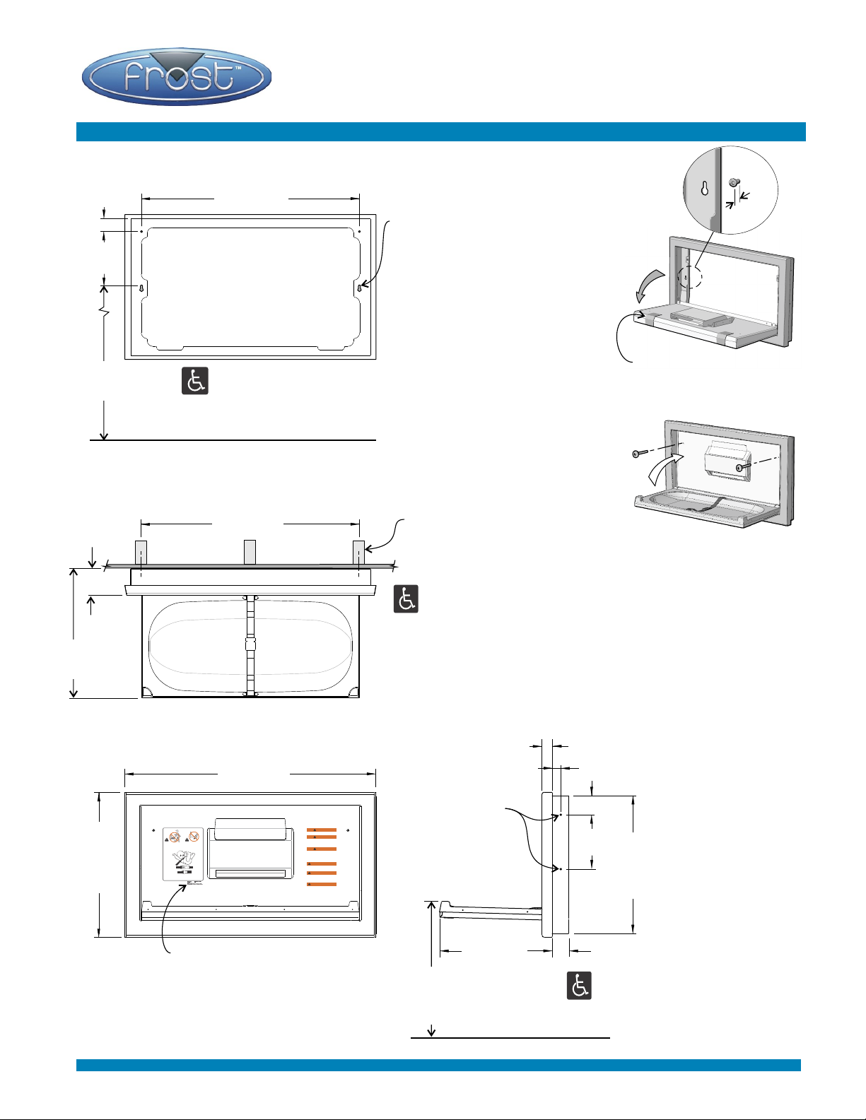
Surface Mounting
32 (81.3)
Surface Mounting and
Mounting Hole Locations
1/4"
2 (5.0)
39.5 (100) Max.
35.5 (90) Min.
3.94
(10)
19
(48.2)
8
(20.3)
Rear View
32 (81.2)
Top View
Surface Mounted
36.90 (93.7)
Floor
1) Drill lower pilot holes (level) into
studding at 32" centres. Insert
first two (2) screws to 1/4" (6mm)
distance from wall (Fig. A).
2) Hang unit off of the lower
mounting screws (screw heads
will fit through “keyhole”, Fig. A).
Tighten screws, adjust level of
unit if required during tightening.
3) Drill and insert last two top
mounting screws.
4) Remove tape, flip up recessed
panel and insert two (2) machine
screws (Fig. B) to secure
recessed panel to complete
installation.
Studding at 32" centres
4.4.1 Maximum Protruding Objects
4.2.5 Forward Reach
4.2.6 Parallel Approach
4.27.4 Operation
ADA Compliant when observing maximum
and minimum mounting heights.
1.48 (3.8)
1.27 (3.2)
Fig. A
Cradle and recessed panel
remain taped together during
installation.
Fig. B
Remove tape, flip up recessed
panel, insert and fully tighten
two (2) 1/2" long machine
screws using Phillips screw
driver.
2.75 (7)
8.00
(20.3)
2.45 (6.2)
20.25 (51.4)
21.3 (54.1)
Avoid serious injury
Never leave
from falling or
a child
sliding out.
unattended.
Always use the restraint system.
Keep one hand on the child at all times.
Product information to
supply when emailing
registration, (see page 2)
Front View
With Door Open
WARNING
Never leave a child unattended.
WARNING
Avoid serious injury from falling
or sliding out. Always use the
restraint system.
WARNING
Designed for Infants Only. Age
up to 3.5 years and weighing less
than 50 lbs. (23 kg). Keep one
hand on the child at all times.
AVERTISSEMENT
Ne jamais laisser un enfant sans
surveillance.
AVERTISSEMENT
Evitez les blessures sérieuses causées
par le glissement. Toujours ultiliser le
system d’attaches.
AVERTISSEMENT
Conçue pour les jeunes enfants
seulement d'âge jusqu'à 3.5 ans et
pesant moins de 23 kg. (50lbs.). Gardez
une main sur l'enfant en tout temps.
Recessed
mounting hole
locations
16.62 (42.3)
Mounting at maximum height
results in this dimension being
34" (86.5), recessed & surface.
Floor
Frost Products Ltd., 5280 John Lucas Dr., Burlington, Ontario, L7L 5Z9, Canada, Ph.: 905.332.5700 www.FrostProductsLtd.com
 Loading...