

Page 1
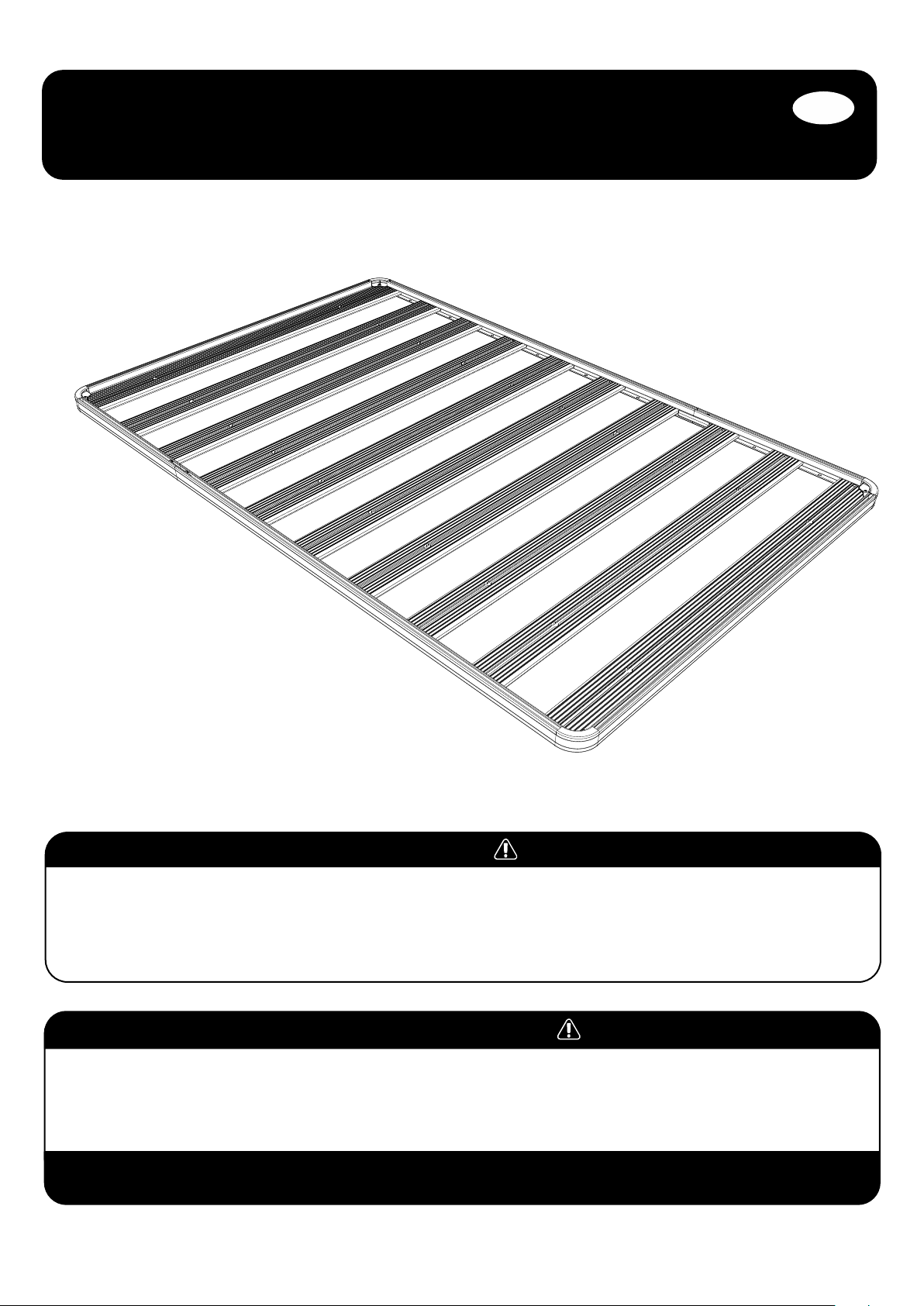
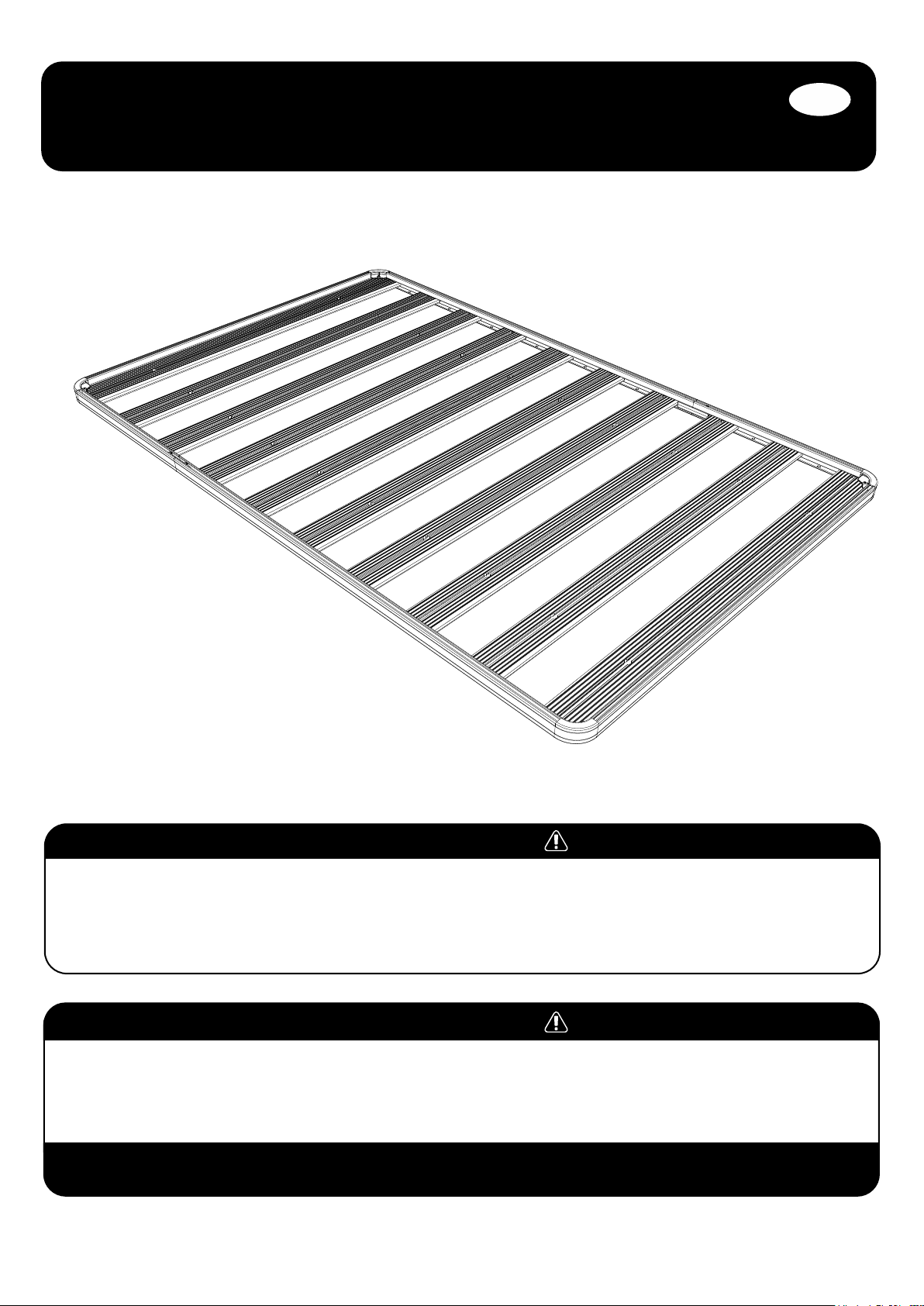
front runner
slimline ii tray
universal assembly
instructions
ENG
RRSTUNI
READ ME !
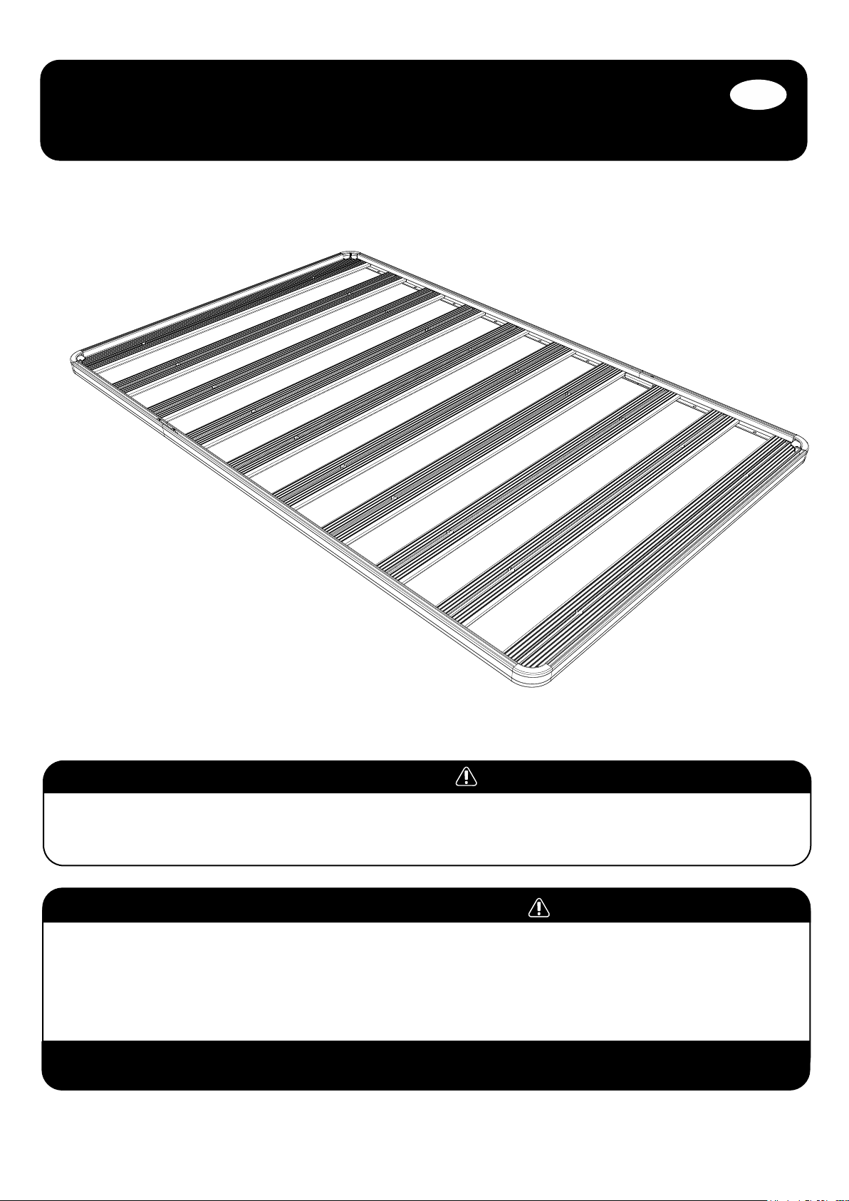
Thank you for purchasing a Front Runner Slimline II Tray.
Before you start, take a moment to familiarize yourself with the Fitting Instructions and the components received.
Refer to Page 2 for a list of all the components, quantities and tools required.
IMPORTANT WARNING!
IT IS CRITICAL THAT ALL FRONT RUNNER PRODUCTS BE PROPERLY AND SECURELY ASSEMBLED AND ATTACHED TO YOUR VEHICLE. IMPROPER ATTACHMENT COULD
RESULT IN AN AUTOMOBILE ACCIDENT, AND COULD CAUSE SERIOUS BODILY INJURY OR DEATH. YOU ARE RESPONSIBLE FOR ASSEMBLING AND SECURING ALL FRONT
RUNNER PRODUCTS TO YOUR VEHICLE, CHECKING THE ATTACHMENTS PRIOR TO USE, AND PERIODICALLY INSPECTING THE PRODUCTS FOR ADJUSTMENT, WEAR AND
DAMAGE. THEREFORE, YOU MUST READ AND UNDERSTAND ALL OF THE INSTRUCTIONS AND PRECAUTIONS SUPPLIED WITH YOUR FRONT RUNNER PRODUCT PRIOR TO
INSTALLATION OR USE. IF YOU DO NOT UNDERSTAND ALL OF THE INSTRUCTIONS AND CAUTIONS, OR IF YOU HAVE NO MECHANICAL EXPERIENCE AND ARE NOT THOROUGHLY
FAMILIAR WITH THE INSTALLATION PROCEDURES, YOU SHOULD HAVE THE PRODUCT INSTALLED BY A PROFESSIONAL INSTALLER OR OTHER QUALIFIED PERSONNEL.
NOTE: Front Runner will not be responsible for any damage caused by the failure to install the product according to these instructions.
Please call us if you have any questions about the installation of this product.
RRSTUNI
_REV_A06
1
© 2019 FRONT RUNNER VEHICLE OUTFITTERS
Page 2
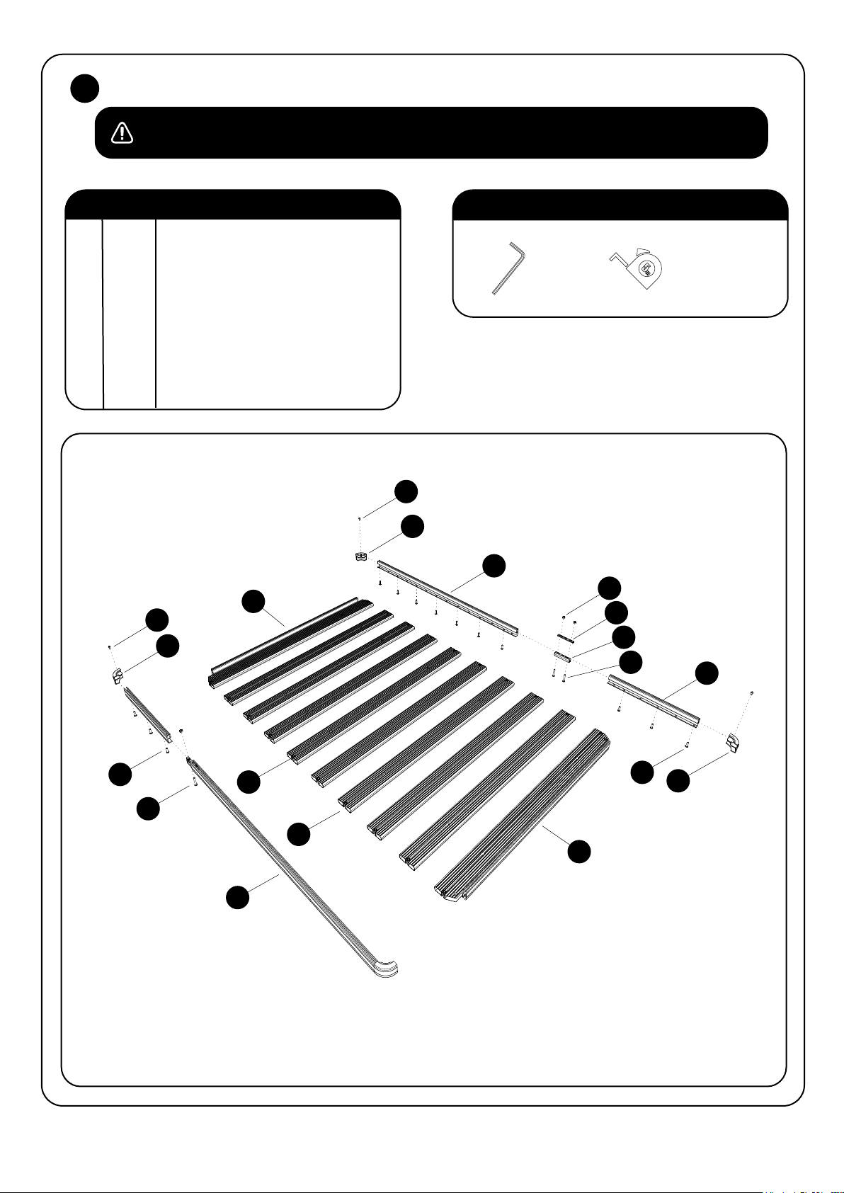
GET ORGANIZED1
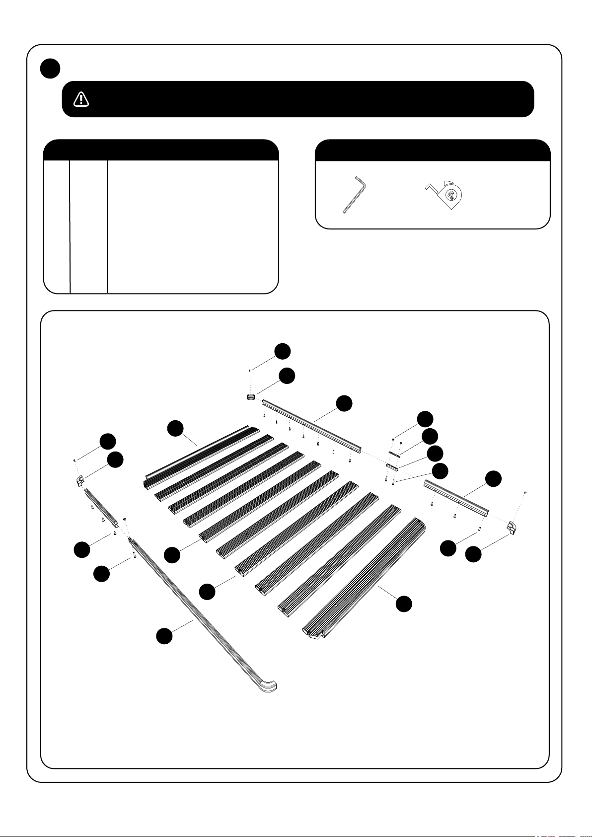
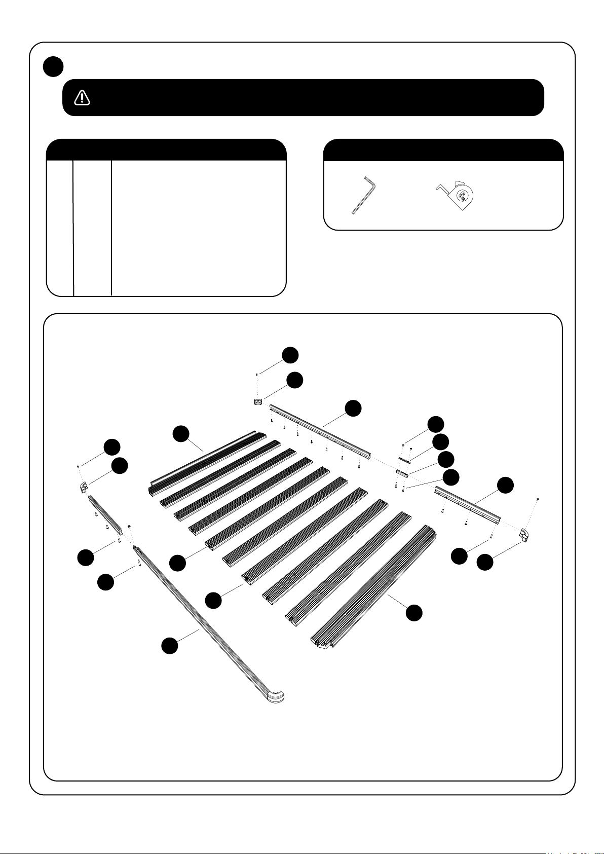
Depending on which size Slimline ll Tray you order, quantities may vary from those pictured.
Here is what you are looking at for RRSTUNI:
IN THE BOX
1 32 X M8 Nyloc Nut
2 4 X M8 x45 Button Head Bolt
3 2 X Thick Joiner Piece
4 2 X Thin Joiner Piece
5 4 X Side Profile
6 4 X Corner
7 2 X Combined Slat
8 28 X M8 x 25 Button Head Bolt
9 12 X Standard Slat
10 4 X M6 x 12 Button Head Bolt
FIGURE 1.1
7
10
6
10
TOOLS NEEDED
4mm
5mm
6
5
1
4
3
2
5
RRSTUNI
8
_REV_A06
8
9
2
9
7
5
2
© 2019 FRONT RUNNER VEHICLE OUTFITTERS
6
Page 3
2
RACK ASSEMBLY - SIDE PROFILES
NOTE: Skip this step if your Slimline II Tray is 1560mm or shorter. you will only have two Side Profiles and assembly
is not required.
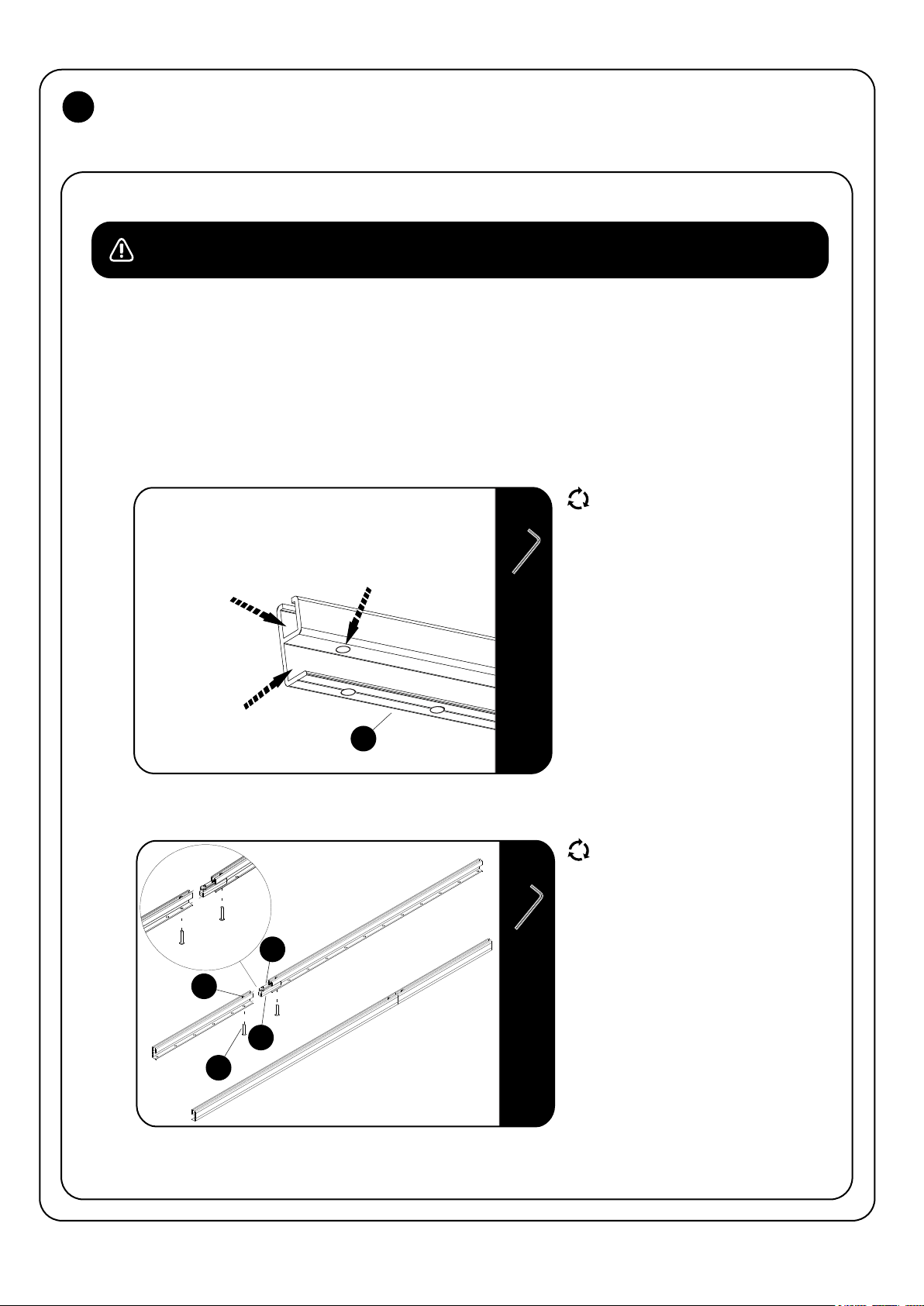
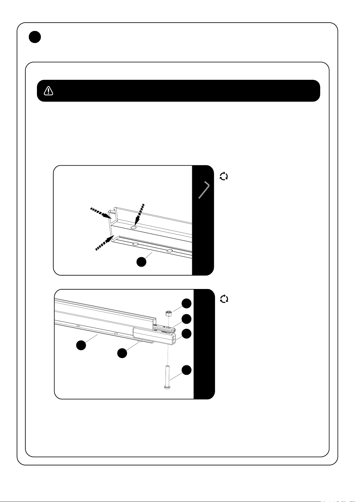
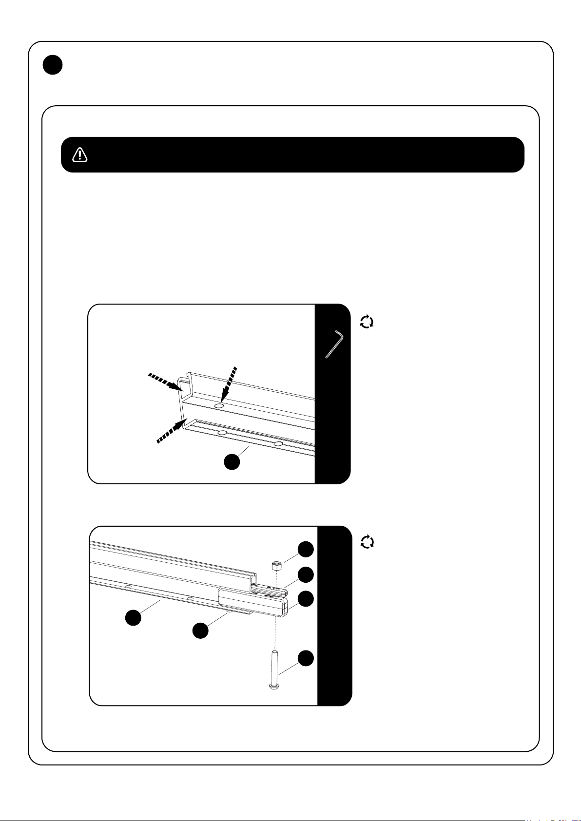
If you have received four lengths of Side Profile (Item 5), you will need to join the pieces together using the Joiners
(Items 3 & 4) to form only two lengths by following the easy steps below.
With the exception of the 2772mm long Slimline II Tray, the joints in the Side Profile will be diagonally opposite each other
once the Tray is assembled.
2.1
2.2
T-slot Channel
U-Channel
1
2
The Side Profiles are supplied in pairs.
Take one profile from each pair, one short
and one long (Except for the 2772mm long
Slimline II rack where the Side Profiles will
be equal length. Even though both pairs
Joiner Hole
5MM
5
4
3
5MM
are the same length it is still important that
you take one Side Profile from each pair).
If you look at the Side Profiles you will see
that at one end there is a hole that goes
through the top and bottom of the
"U" Channel.
(Refer to Image 2.1). These are the
Joiner Holes that you will be using.
Insert a Thick Joiner (Item 3) into the
"U" Channel of the Side Profile lining
up the first hole with the hole in the side
profile as show in 2.2.
Now grab a Thin Joiner (Item 4) and
Nyloc Nut (Item 1). Slide the Joiner into the
"T-slot", followed by a Nyloc Nut.
The Nyloc Nut should sit on top of the
Thin Joiner with the "Dome" of the
Nyloc Nut facing up. Line up the outer
hole of the Thin Joiner and Nyloc Nut with
the Joiner Hole and loosely fasten it all
together using a M8 x 45 Button Head Bolt
(Item 2) and a 5mm Allen Wrench.
Slide the matching Side Profile over the two
Joiner pieces, remembering to insert a
Nyloc Nut, and fasten once again using a
M8 x 45 Button Head Bolt. Repeat the above
steps for the other side.
RRSTUNI
_REV_A06
4MM
3
© 2019 FRONT RUNNER VEHICLE OUTFITTERS
Page 4
3
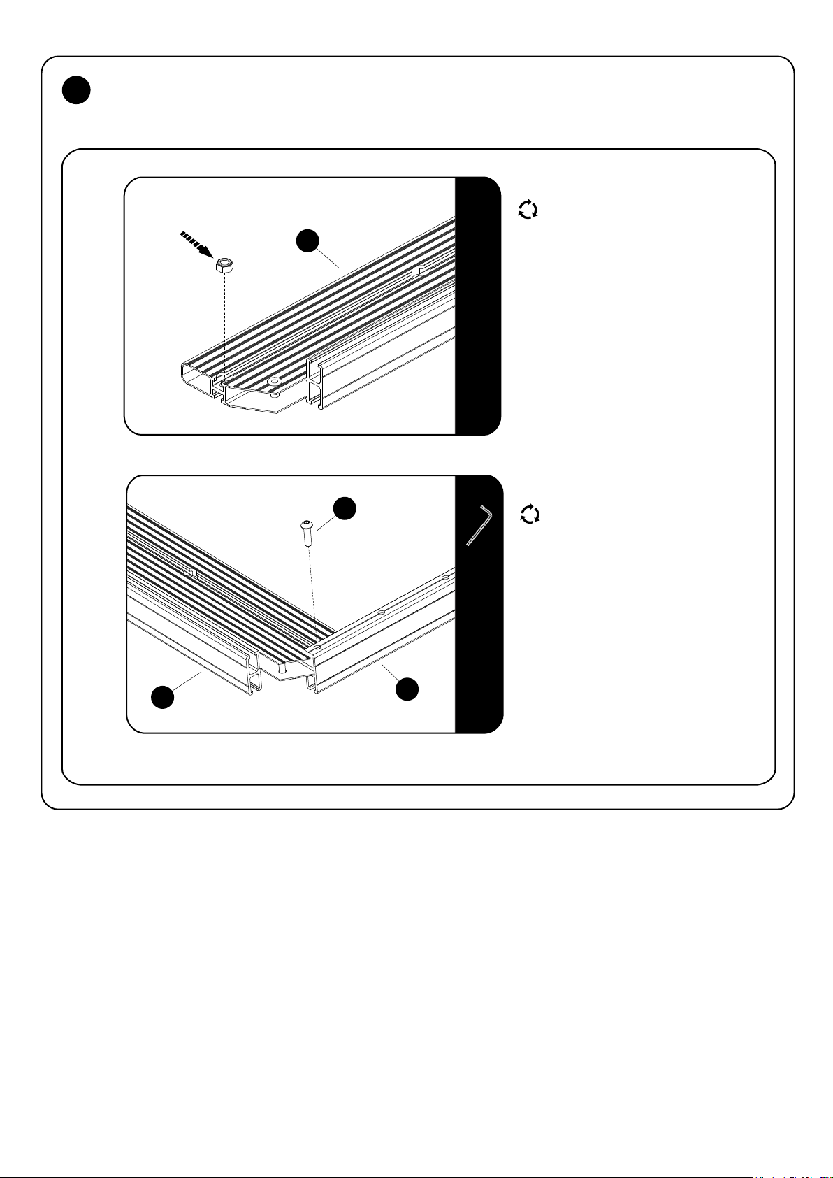
RACK ASSEMBLY - COMBINED SLATS AND STANDARD SLATS
3.1
3.2
3.3
Nyloc Nut
7
9
7
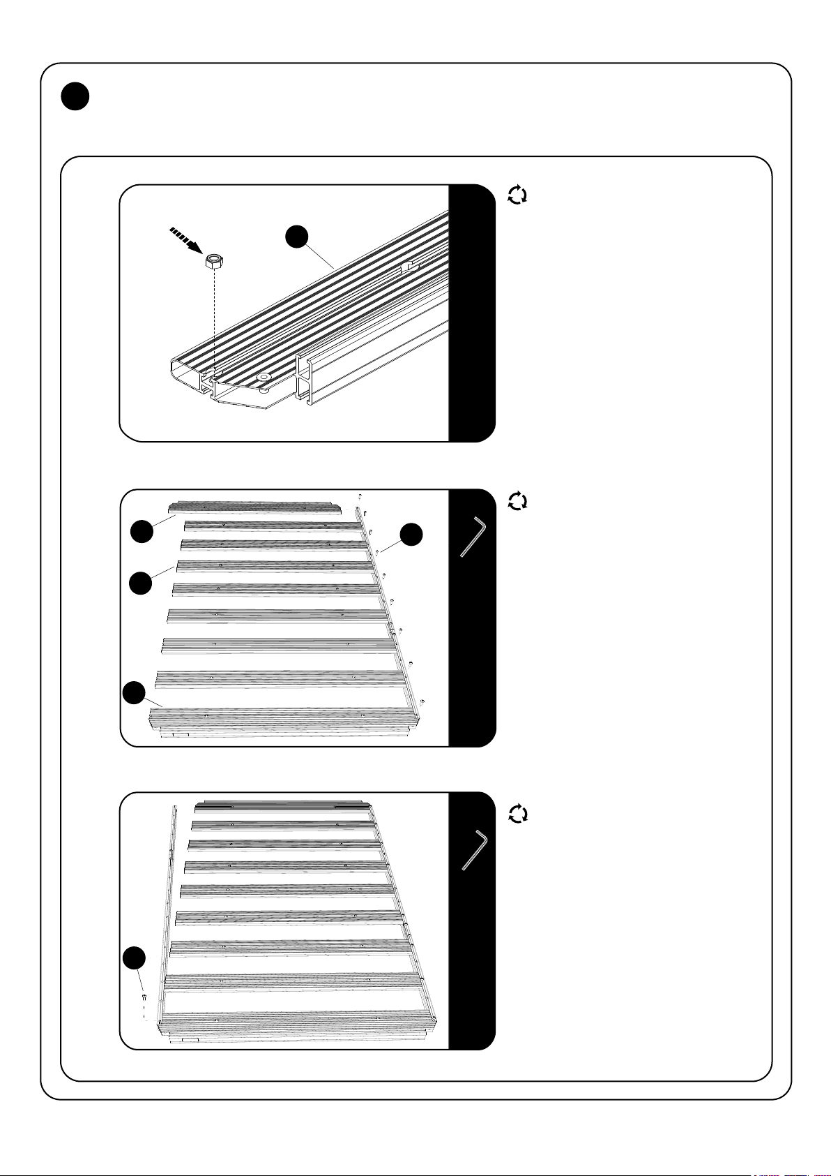
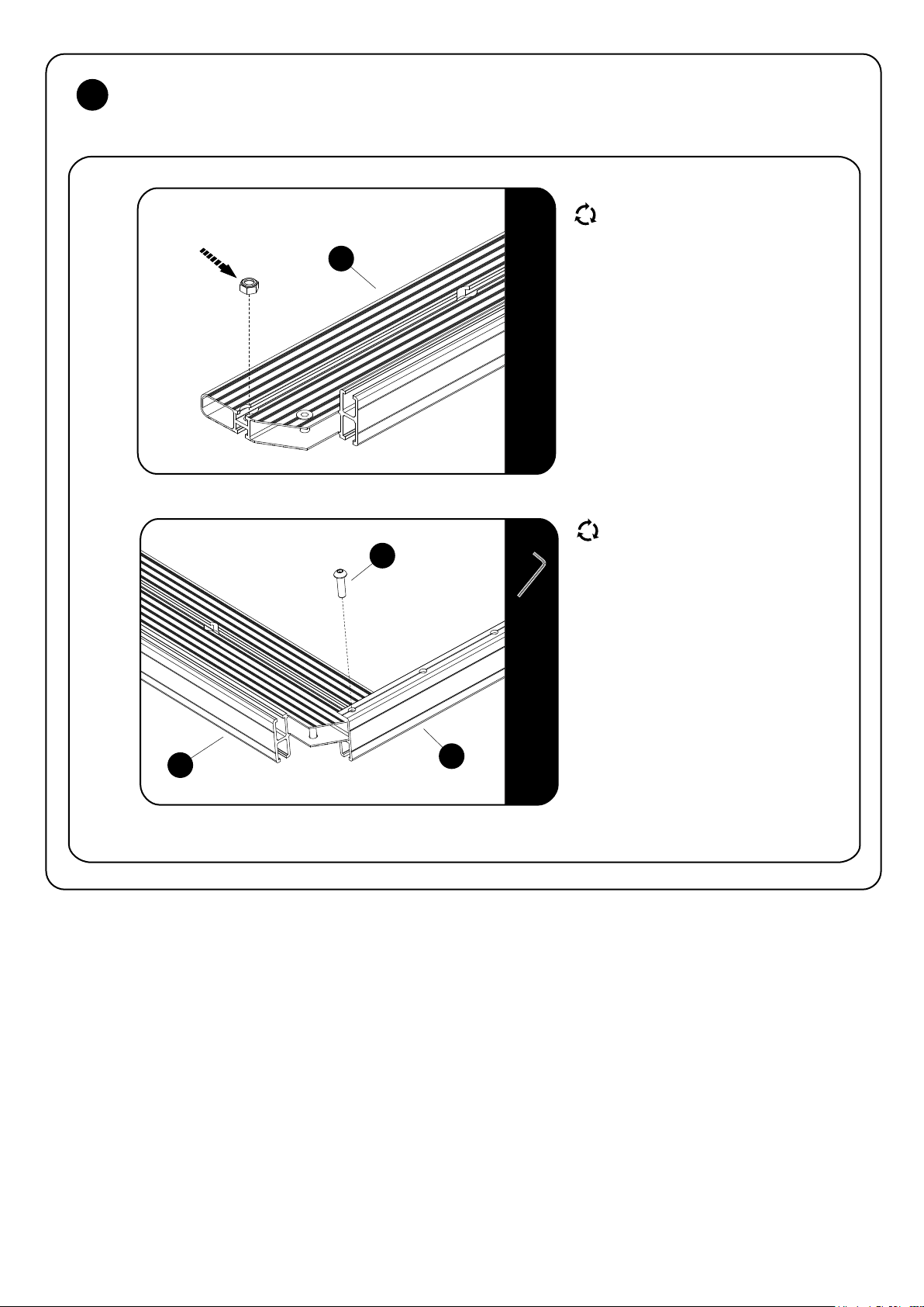
Look at the Combined Slats and Standard
Slats (Item 7 & 9) and ensure that there is a
Nyloc Nut inserted into each machined end
7
8
5MM
5MM
pocket. If the Nyloc Nut has fallen out
during shipping, insert it back into the
pocket as shown.
Turn the Combined Slat (Item 7) and the
Side Profile Assembly upside down. Ensure
that the nut in the Combined Slat is at the
bottom. Push the one end of the Combined
Slat into the Side Profile assembly and
align the holes.
Use a M8 x 25 Button Head (Item 8) and
loosely tighten using a 5mm Allen Wrench.
Do the same with the second Combined Slat
on the other end of the Side Profile Assembly.
Take a Standard Slat (Item 9) and as with
the Combined Slat, slide the one end into the
Side Profile Assembly as shown. Ensure that
the nut is at the bottom.
Use a M8 x 25 Button Head Bolt (Item 8)
and loosely fasten the Standard Slat to the
Side Profile using a 5mm Allen Wrench.
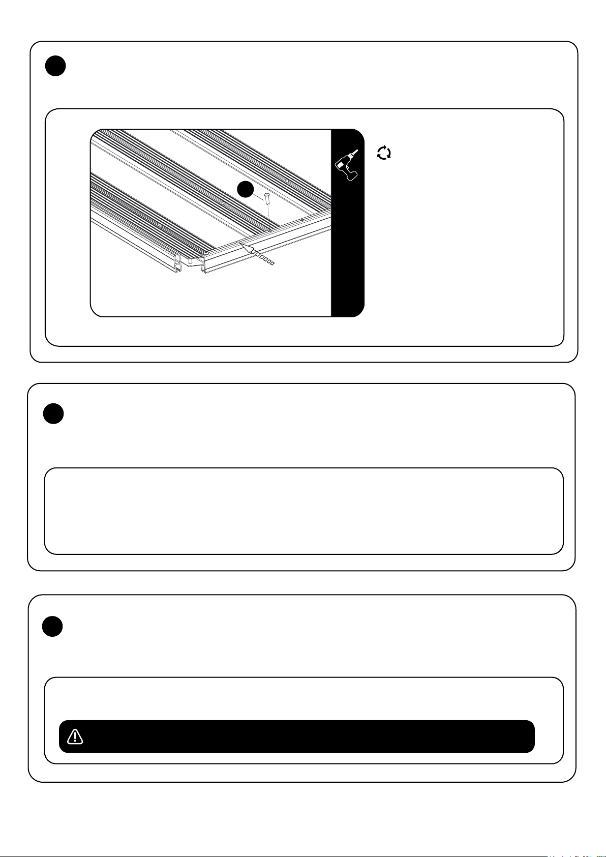
Repeat the process for the remaining
Standard Slats making sure that there
is an open hole in the Side Profile in between
each slat.
Take the other Side Profile Assembly and
starting at the one end push the Side Profile
over the ends of the Combined Slat and
Standard Slats, aligning the holes and loosely
inserting the M8 x 25 Button Heads as you
work your way to the Combined Slat
at the other end.
RRSTUNI
_REV_A06
8
4
© 2019 FRONT RUNNER VEHICLE OUTFITTERS
Page 5
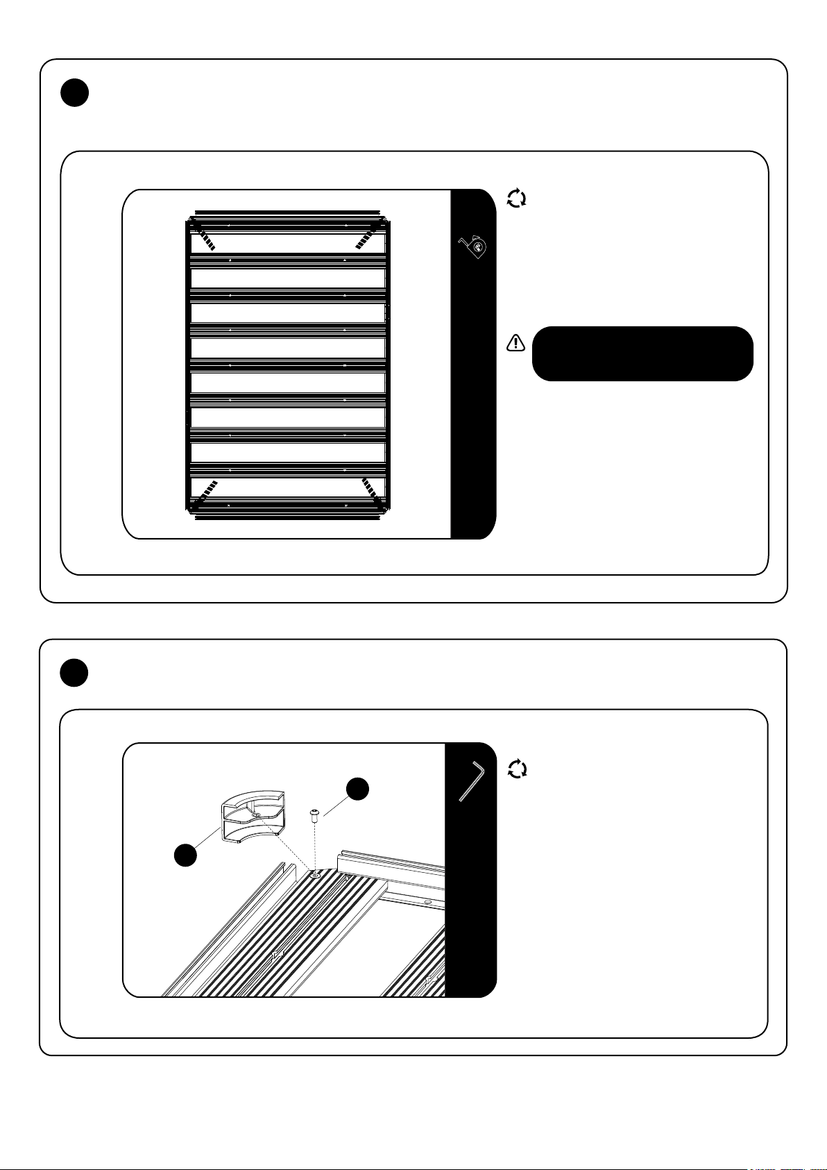
3
RACK ASSEMBLY - STANDARD SLATS
3.4
Square the Side Profiles and Slats up before
fully tightening all the fasteners.
Using a tape measure, measure from the one
corner across to the other corner. Do the
same on the opposite corners, if the two
measurement are the same the rack will be
square.
Fully tighten all the M8 x 25 Button Head Bolts.
The recommended torque setting for the
M8 Button Head Bolts is 20 Nm or
15 ft lb.
4
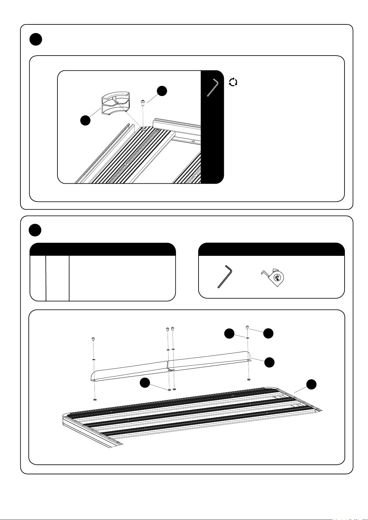
RACK ASSEMBLY- CORNERS
4.1
Flip the tray right side up.
10
4MM
6
Push the Corner into position as shown,
aligning the hole in the Corner with the
Rivnut already inserted in the Combined Slat.
Use a M6 x 12 Button Head Bolt (Item 10)
and fasten the Corner in position.
RRSTUNI
_REV_A06
5
© 2019 FRONT RUNNER VEHICLE OUTFITTERS
Page 6
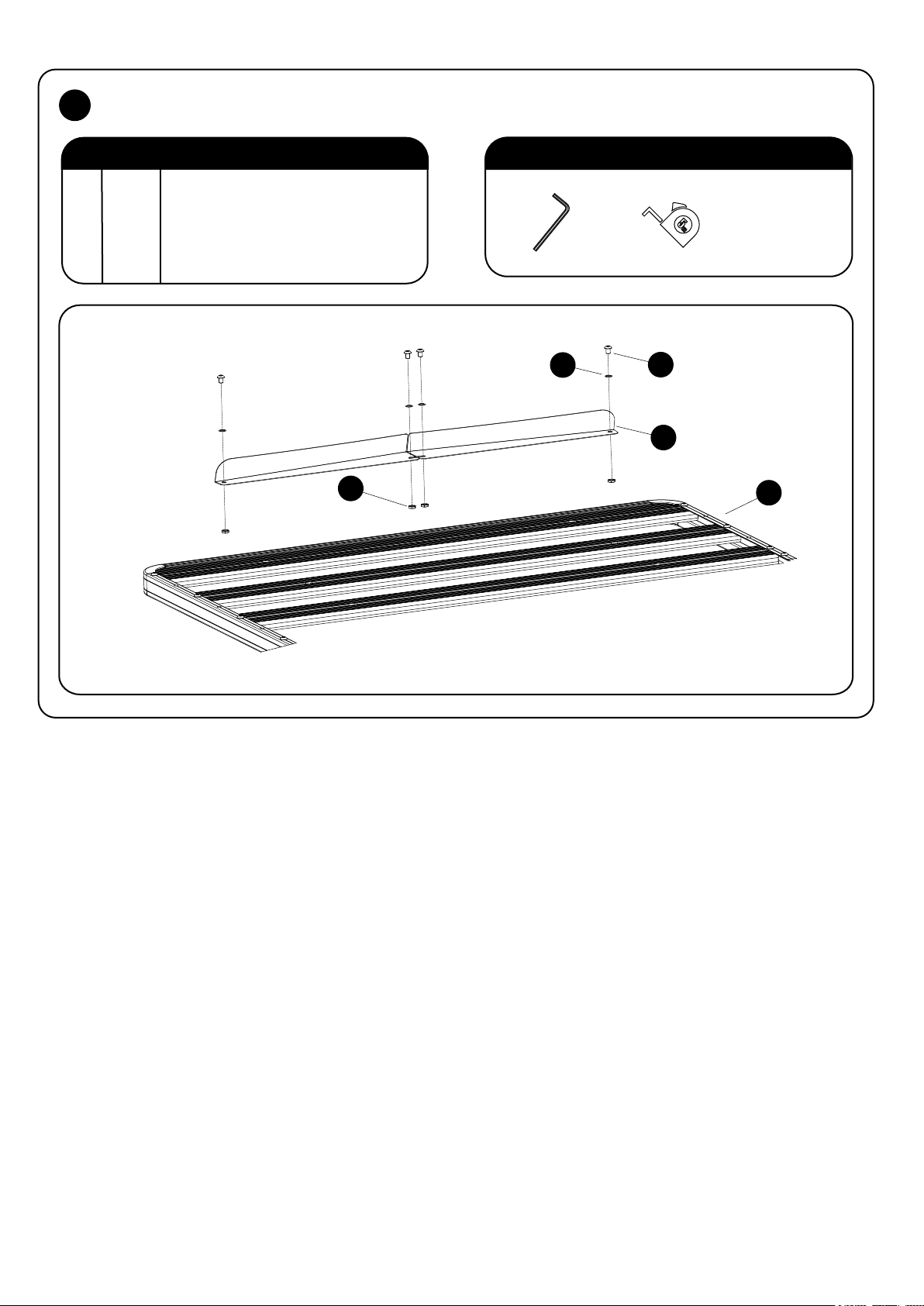
RACK ASSEMBLY - WIND DEFLECTOR 5
IN THE BOX
1 1 Slimline II Tray
2 4 M8 Half Nut
3 2 Wind Deflector (1LH + 1RH)
4 4 Schnorr Washer
5 4 M8 x 12 Button Head Bolt
FIGURE 1.2
TOOLS NEEDED
5mm
4
2
5
3
1
RRSTUNI
_REV_A06
6
© 2019 FRONT RUNNER VEHICLE OUTFITTERS
Page 7
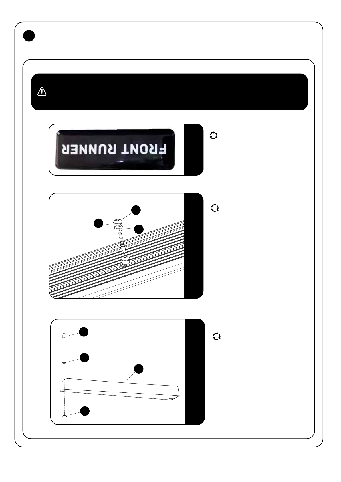
6
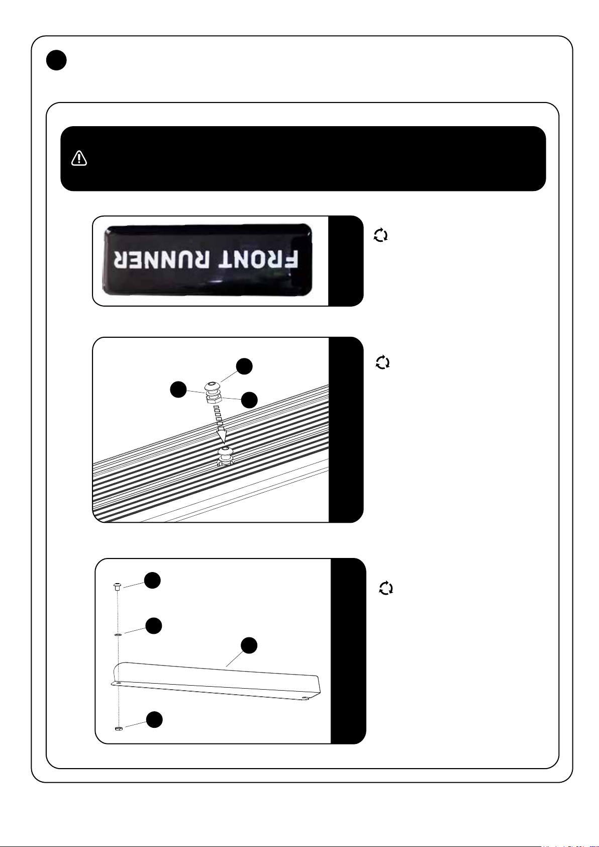
RACK ASSEMBLY - WIND DEFLECTOR
NOTE : The Wind Deflector must be fitted to the underside of the front Combined Slat.
If you are going to put a Leg or Foot on the Combined Slat (Recommended), you will need to slide the M8 Bolt
used for attaching these into the Machined Slots before assembling the Wind Deflector.
9MM
6.1
6.2
Ensure that your Slimline II Tray is upside
down. Check by looking at the product
sticker. It should be upside down as shown.
Insert two Button Head Bolts, M8 Half Nuts
5
4
2
and Schnorr Washers (Items 2, 4 & 5)
assemblies into the Combined Slat
as shown. Slide them to the center of the
Combined Slat making sure that the
Schnorr Washer is above the T-slot Channel.
RRSTUNI
6.3
_REV_A06
5
4
3
2
7
Assemble Items 2, 4 & 5 to both LH & RH
Wind Deflectors (Item 3) as shown.
© 2019 FRONT RUNNER VEHICLE OUTFITTERS
Page 8
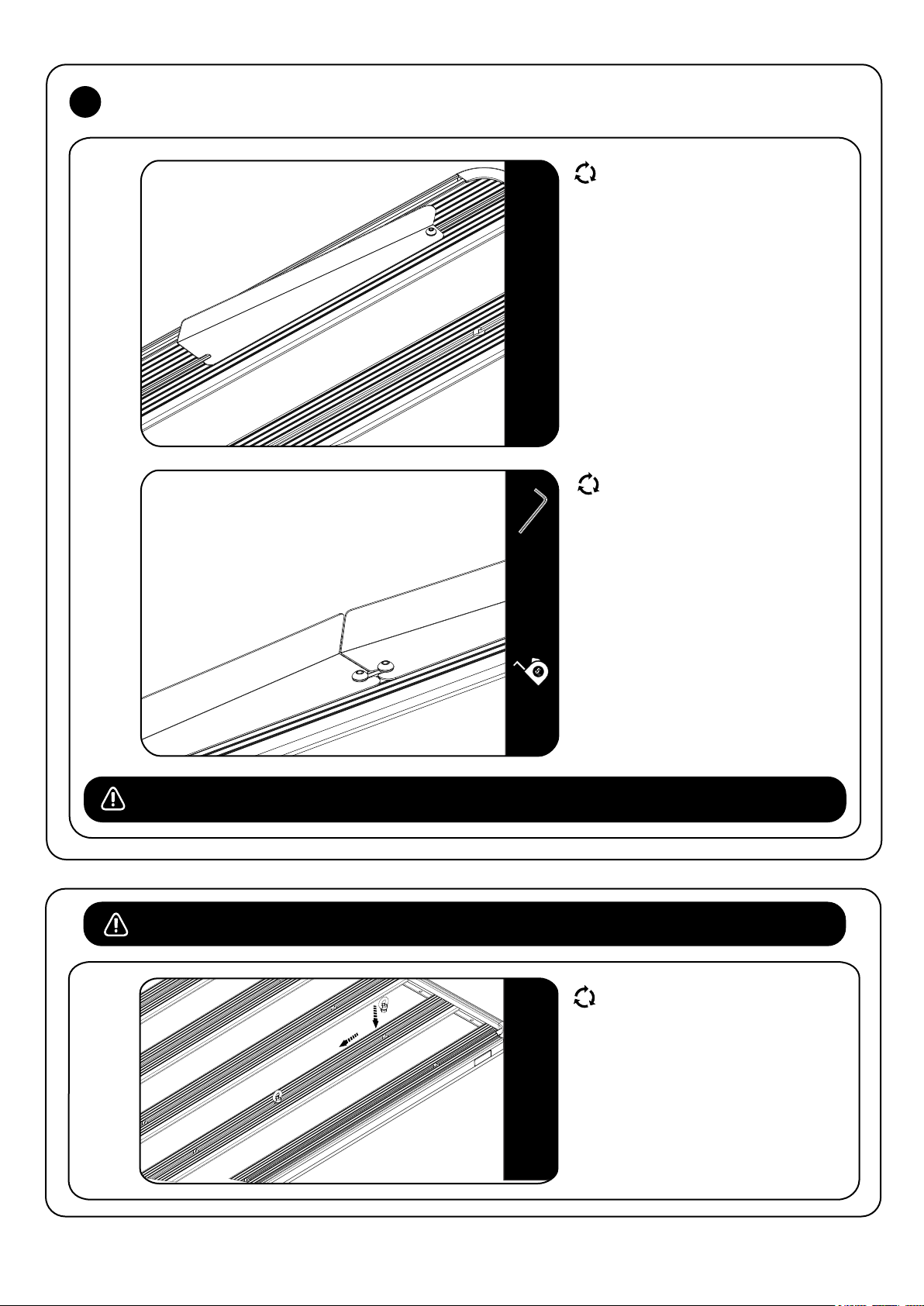
6
RACK ASSEMBLY - WIND DEFLECTOR
6.4
6.5
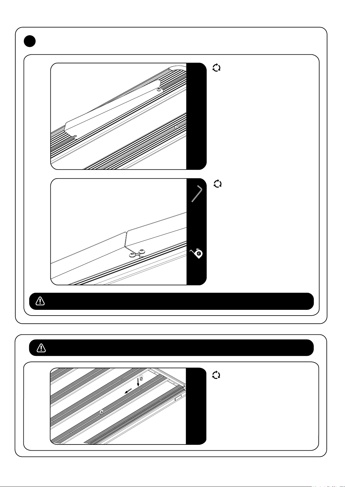
Insert the nut assembled to the
Wind Deflector in the Combined Slat T-slot
Pocket and slide to the side as shown in
Figure 8.4.
Repeat for the other half of the
Wind Deflector.
Center the Wind Deflector on the rack and
move the bolt assemblies from Figure 8.2
into the slots as shown in Figure 8.5.
5MM
NOTE : Once the rack is fitted to the vehicle, take it for a test drive. Should there be excessive wind noise try moving the two
Wind Deflectors slightly apart, leaving a gap of about 20 - 30mm.
USEFULL TIP - PRE-LOAD TIE DOWN RINGS
It is usefull to fit Tie-Down Rings
(RRAC012) to your Front Runner Rack for
future use before you fit any accessories.
Insert the Tie Down Rings into the machined
slots and position them in the center of the
rack.
RRSTUNI
_REV_A06
8
© 2019 FRONT RUNNER VEHICLE OUTFITTERS
Page 9

7
CHECK YOUR VEHICLE INSTALLATION GUIDE
7.1
Now that your Slimline II Tray is assembled, get your Rack Kit Installation Guide out and follow the instructions
to fit the Slimline II Tray to your specific vehicle.
8
HOW TO CARE FOR YOUR FRONT RUNNER GEAR
FRONT RUNNER RACKS AND ACCESSORIES ARE HAPPIEST COVERED IN MUD
But in order to maintain full functionality of the rack slots and any moving parts, you may want to give
your gear a bath now and again.
It's easy! Take care of your Front Runner gear the same way you do the exterior of your vehicle:
Rinse with clean water and wipe down with a soft dry cloth. For stubborn spots, use a soft brush and mild soap.
If you really want to baby your gear, feel free to lightly wax the surfaces or use a protective spray with UV
inhibitors. Just be sure not to use compound waxes that contain abrasives.
In salty coastal climates, or snowy regions where salt is used to clear roadways, applying a silicone based oil
or spray to nuts and bolts will help prevent corrosion.
WHETHER YOU LIKE TO ROLL DIRTY OR CLEAN, YOUR FRONT RUNNER GEAR WILL GIVE YOU MANY YEARS OF SERVICE!
9
INSTALL OTHER VEHICLE AND RACK ACCESSORIES
Now's the time to visit your favorite Front Runner Dealer in person or online.
Be sure to tag us. We love to see our gear in action! #FrontRunnerOutfitters #BornToRoam
Share your adventures on:
RRSTUNI
_REV_A06
9
© 2019 FRONT RUNNER VEHICLE OUTFITTERS
Page 10
front runner
Slimline II Dachträger
Universalmontageanleitung
DEU
RRSTUNI
BITTE ZUERST LESEN
Vielen Dank, dass Du Dich für ein Trägersystem von Front Runner entschieden hast.
Bevor Du beginnst, nimm Dir einen Moment Zeit und mache Dich mit der Montageanleitung
und allen Komponenten vertraut.
WICHTIGER HINWEIS
STELLE UNBEDINGT SICHER, DASS ALLE FRONT RUNNER PRODUKTE ORDNUNGSGEMÄß ZUSAMMENGEBAUT UND SICHER AN DEINEM FAHRZEUG BEFESTIGT
SIND. EINE UNSACHGEMÄßE INSTALLATION KÖNNTE ZU EINEM UNFALL UND ZU ERNSTHAFTEN FOLGEN UND SCHÄDEN DRITTER FÜHREN, BIS HIN ZU TÖDLICHEN
VERLETZUNGEN. DU BIST DAFÜR VERANWORTLICH, ALLE FRONT RUNNER PRODUKTE ZUSAMMENZUBAUEN UND AN DEINEM FAHRZEUG ZU SICHERN, DIE
BEFESTIGUNGEN VOR EINER VERWENDUNG REGELMÄßIG AUF EINSTELLUNG, ABNUTZUNG ODER SCHÄDEN ZU PRÜFEN. LIES DAHER UNBEDINGT VOR DER
MONTAGE ODER DER VERWENDUNG ALLE MIT DEINEM FRONT RUNNER PRODUKT GELIEFERTEN ANWEISUNGEN UND HINWEISE. FALLS DU NICHT ALLE
ANWEISUNGEN ODER HINWEISE VERSTEHST ODER DU KEINE TECHNISCHE ERFAHRUNG BESITZT UND MIT DEM ZUSAMENBAUEN NICHT VERTRAUT BIST,
SOLLTEST DU DAS PRODUKT VON TECHNISCHEM FACHPERSONAL ODER EINER ANDERWEITIG QUALIFIZIERTEN PERSON VERBAUEN LASSEN.
HINWEIS: Front Runner übernimmt keine Verantwortung oder Haftung für Schäden durch unsachgemäße Montage, die von der Montageanleitung abweicht.
Solltest Du irgendwelche Fragen zur Installation dieses Produktes haben, kontaktiere uns einfach.
RRSTUNI
_REV_A05
1
© 2019 FRONT RUNNER OUTFITTERS
Page 11
1
ERSTE VORBEREITUNGEN
Je nach Größe Deines Slimline II Dachträgers, kann die Anzahl der unten aufgeführten Bestandteile abweichen.
Im folgenden die Bestandteile für das Beispiel dieser Universalmontageanleitung:
INHALT
1 32 X M8 Selbstsichernde Mutter
2 4 X M8 x 45 Rundkopfschraube
3 2 X Dickes Verbindungsstück
4 2 X Dünnes Verbindungsstück
5 4 X Seitenprofil
6 4 X Eckstück
7 2 X Kombileiste
8 28 X M8 x 25 Rundkopfschraube
9 12 X Querleiste
10 4 X M6 x 12 Rundkopfschraube
ABBILDUNG 1.1
7
10
6
10
DU BENÖTIGST
4 MM
5 MM
6
5
1
4
3
2
5
RRSTUNI
8
_REV_A05
8
9
2
9
7
5
2
© 2019 FRONT RUNNER OUTFITTERS
6
Page 12
2
MONTAGE DER SEITENPROFILE
HINWEIS: Überspringe diesen Schritt, wenn Dein Slimline II Dachträger in der Länge 1560 mm oder kürzer ist.
In diesem Fall hast Du nur zwei Seitenprofile und es ist kein Zusammenbau erforderlich.
Falls Du vier Längen des Seitenprofils (Teil5), erhalten hast, musst Du die Teile unter der Verwendung der
Verbindungsstücke (Teil 3 & 4 ) zusammenbauen, sodass Du zwei Längen erhältst. Gehe dafür gemäß der
folgenden Schritte vor.
Mit Ausnahme eines 2772 mm langen Slimline II Dachträgers, sind die Verbindungen nach dem
Zusammenbau in den Seitenprofilen des Dachträgers einander diagonal gegenüber.
2.1
2.2
T-Nut
U-Nut
5
Verbindungsbohrung
5
2
Die Seitenprofile sind paarweise
verpackt. Entnimm jeweils ein
Seitenprofil von jedem Paar, ein kurzes
und ein langes (bei einem 2772 mm
langen Slimline II Dachträgers haben die
Seitenprofile die gleiche Länge, entnimm
auch in diesem Fall jeweils ein
5 MM
1
4
3
2
4MM
Seitenprofil von jedem Paar).
Wenn Du Dir die beiden Seitenprofile
ansiehst, wirst Du feststellen, dass eine
Bohrung durch das obere und untere
Ende des "U"-Nut des Seitenprofils geht
(siehe Abb. 2.1).
Dies sind die Verbindungsbohrungen, die
Du verwenden wirst.
Führe ein dickes Verbindungsstück
(Teil 3) in die U-Nut des Seitenprofils
und richte die erste Bohrung mit der
Verbindungsbohrung aus. Lasse hierbei
zwei Bohrungen über der Kante des
Seitenprofils frei (Abb. 2.2).
Nimm Dir nun ein dünnes
Verbindungsstück (Teil 4) und eine
selbstsichernde Mutter (Teil 1). Schiebe
das dünne Verbindungsstück in die TNut,
gefolgt von der selbstsichernden
Mutter. Die selbstsichernde Mutter sollte
oben auf dem dünnen Verbindungsstück
sitzen, wobei die "Kuppe" der Mutter
nach oben zeigt.
Richte die äußere Bohrung des dünnen
Verbindungsstücks und die
selbstsichernde Mutter aus und ziehe alles
mit einer M8 x 45 Rundkopfschraube
(Teil 2) und einem 5 mm-Innensechskant
handfest an.
Schiebe das zugehörige Seitenprofil über
die zwei Verbindungsstücke und denk
daran, eine selbstsichernde Mutter
einzusetzen. Befestige auch diese
Verbindung mit einer m8 x 45
Rundkopfschraube. Wiederhole die oben
beschriebenen Schritte für die andere
Seite.
RRSTUNI
_REV_A05
3
© 2019 FRONT RUNNER OUTFITTERS
Page 13
MONTAGE DER ERSTEN KOMBILEISTE
3
3.1
3.2
Selbstsichernde Mutter
7
Schau Dir die Kombileiste an (Teil 7)
und stell sicher, dass in jeder
Endaussparung jeweils eine
selbstsichernde Mutter eingesetzt ist.
Falls die selbstsichernde Mutter
7
8
5 MM
5
während des Transports herausgefallen
sein sollte, setze sie mit der "Kuppe"
nach oben zurück in die Aussparung
(Abb. 3.1).
Drehe die Kombileiste (Teil 7) einmal
um, sodass die Unterseite nach oben
zeigt (Abb. 3.2). Schiebe die beiden
Seitenprofile über die Kombileiste und
richte die Bohrungen aus. Die
Endbohrung des Seitenprofls sollte auf
einer Höhe mit der Bohrung der
Kombileiste sein.
Verwende eine M8 x 25
Rundkopfschraube (Teil 8) und ziehe sie
mit einem 5 mm-Innensechskantschlüssel
fest.
Die Plattform bleibt mit der Unterseite
nach oben gedreht, für die Montage der
7 Querleisten.
RRSTUNI
_REV_A05
4
© 2019 FRONT RUNNER OUTFITTERS
Page 14
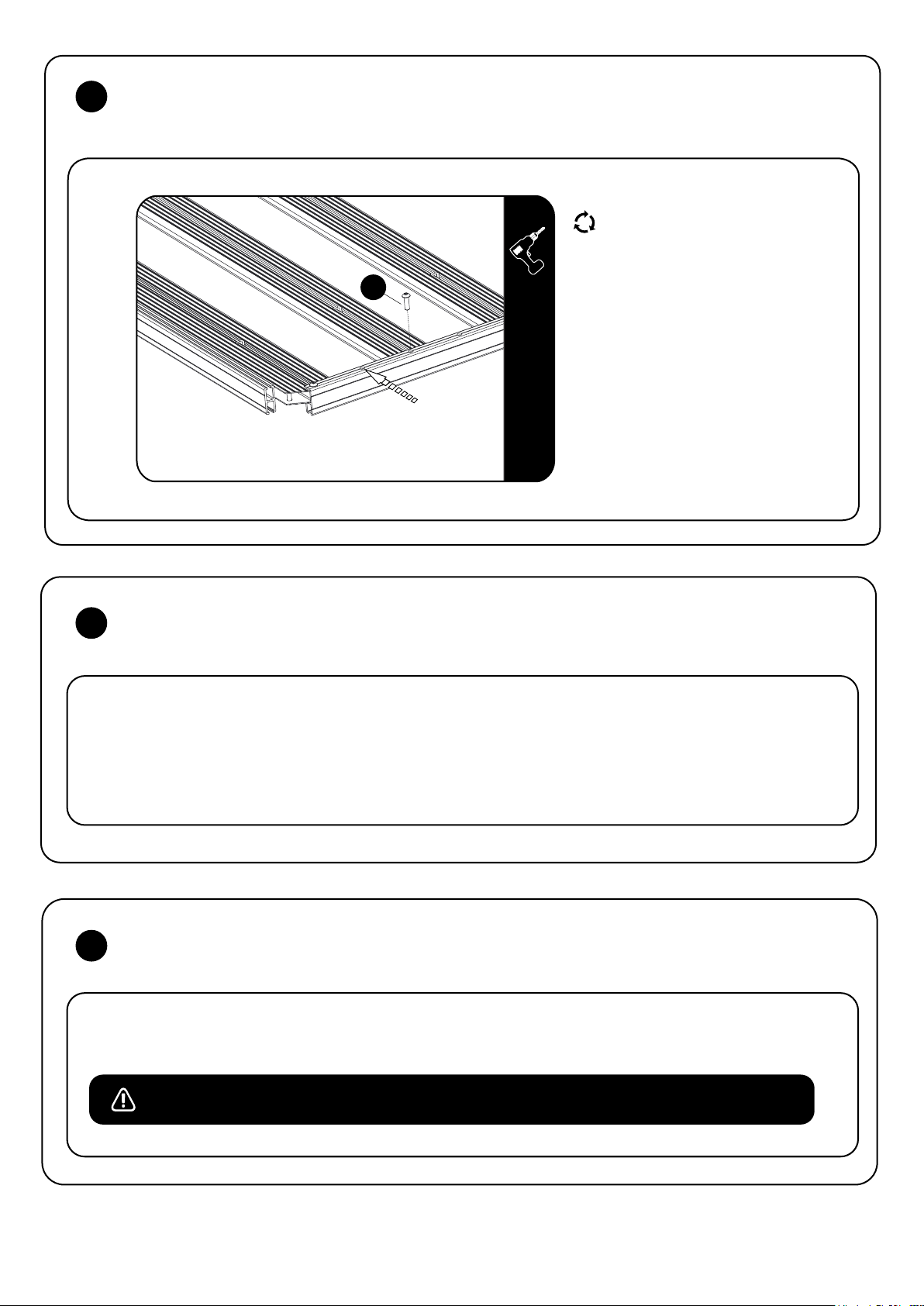
MONTAGE DER QUERLEISTEN
4
4.1
Freigelassene Bohrung
zwischen den Leisten beachten!
5
MONTAGE DER ZWEITEN KOMBILEISTE
Nimm eine Querleiste (Teil 9) und
vergewissere Dich genau wie bei der
Kombileiste, dass die selbstsichernde
Mutter in die eingearbeitete
Endaussparung eingesetzt ist. Schiebe die
Querleiste zwischen die zwei Seitenprofile,
8
9 MM
wobei die Seite mit der selbstsichernden
Mutter nach unten zeigen muss.
Positioniere die Querleiste so, dass die
Bohrung in der Leiste mit der dritten
Bohrung im Seitenprofil ausgerichtet ist
(Abb. 4.1).
Verwende eine M8 x 25 Rundkopfschraube
(Teil 8) und ziehe sie mit einem 5 mm-
Innensechskantschlüssel leicht an dem
Seitenprofil an.
Wiederhole diesen Prozess mit den
verbleibenden Querleisten und lass immer
eine Bohrung in den Seitenprofilen
zwischen den Leisten aus (Abb. 4.1).
5.1
6
6.1
Schau Dir nochmal Schritt 3.1 an - Schiebe danach die zweite Kombileiste in die zwei Seitenprofile und befestige sie,
wie in Schritt 3.2 beschrieben.
FESTZIEHEN ALLER SCHRAUBEN
Ziehe mit Deinem 5 mm-Innensechskantschlüssel alle Rundkopfschrauben fest.
Das empfohlene Drehmoment für die M8 Rundkopfschrauben ist 20 Nm oder 15 ftlb.
RRSTUNI
_REV_A05
5
© 2019 FRONT RUNNER OUTFITTERS
Page 15
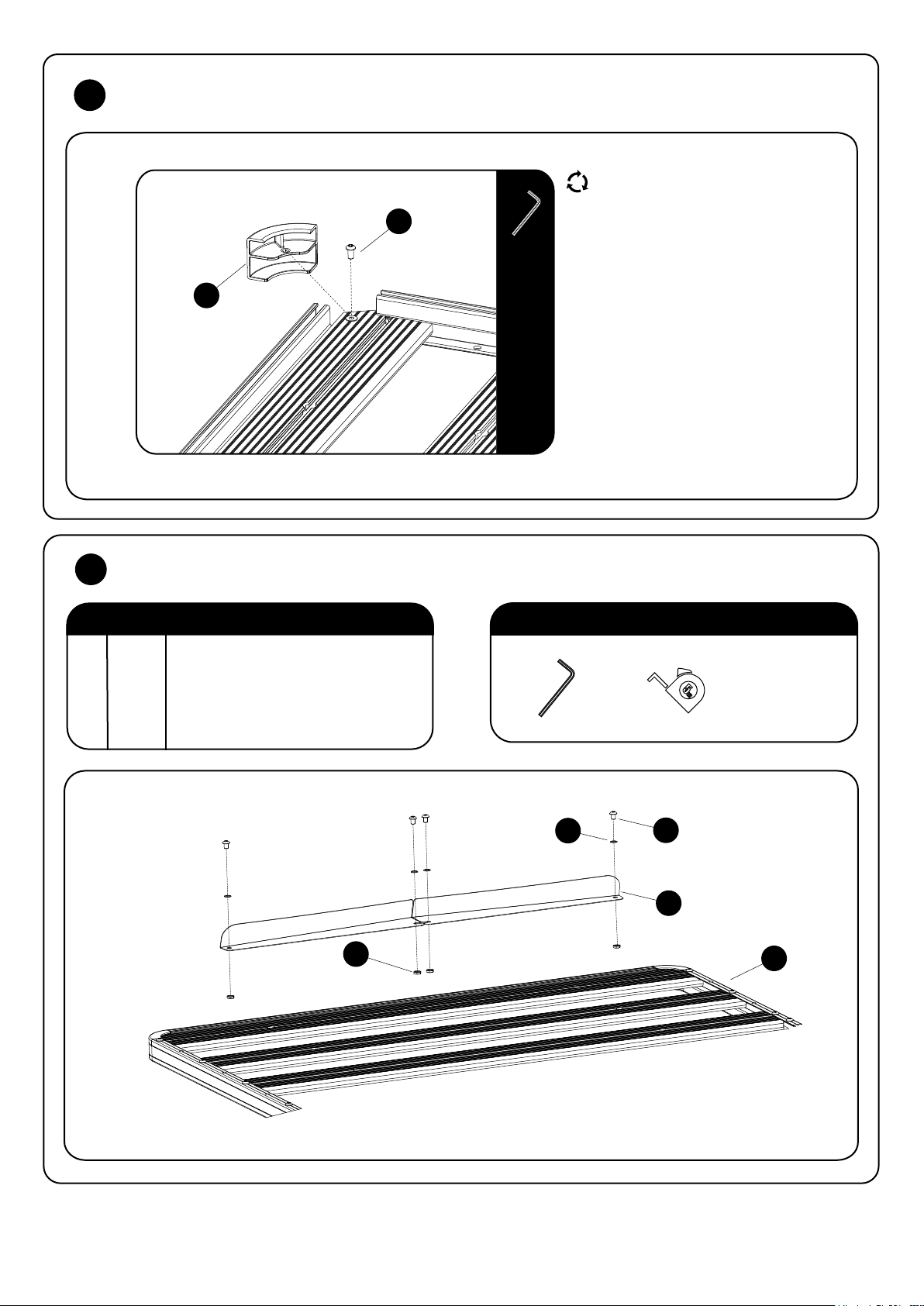
7
MONTAGE DER DACHRÄGER-ECKEN
7.1
6
8
MONTAGE DES WINDABWEISERS
INHALT
10
4 MM
DU BENÖTIGST
Dreh die Plattform herum, sodass die
Oberseite wieder nach oben zeigt.
Schiebe das Eckstück wie dargestellt an
seine Position und richte dabei die
Bohrung im Eckstück mit der bereits in
der Kombileiste eingesetzten
Einziehmutter aus. Nimm einen 4 mmInnensechskant und eine M6 x 12
Rundkopfschraube (Teil 10) und ziehe
das Eckstück in der Position fest.
HINWEIS: Wenn Du bei der Montage
des Slimline II Dachträgers an Deinem
Fahrzeug auch gleichzeitig Zubehör
anbringen möchtest, solltest Du die
Eckstücke zunächst weglassen.
Vergewissere Dich in der jeweiligen
Montageanleitung, ob das der Fall ist.
1 1 Slimline II Dachträger
2 4 M8 Halbmutter
3 2 Windabweiser (1L + 1R)
4 4 Unterlegscheibe
5 4 M8 x 12 Rundkopfschraube
ABBILDUNG 1.2
5 MM
4
2
5
3
1
RRSTUNI
_REV_A05
6
© 2019 FRONT RUNNER OUTFITTERS
Page 16
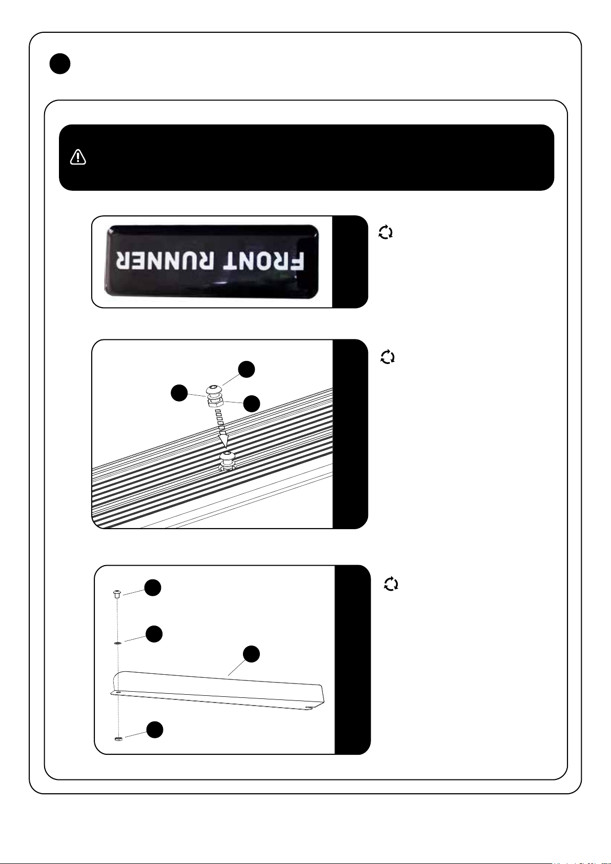
8
MONTAGE DES WINDABWEISERS
HINWEIS: Der Windabweiser wird an der vorderen Kombileiste montiert.
Falls Du ein Befestigungsfuß oder -bein an der Kombileiste montieren musst, musst Du die entsprechende M8 Schraube
zur Befestigung in die eingearbeitete Nut der Kombileiste schieben, vor der Montage des Windabweisers.
9MM
8.1
8.2
Vergewissere Dich, dass Dein Slimline II
Dachträger umgedreht, mit der Oberseite
nach unten liegt. Das kannst Du an dem
Logo erkennen, indem es wiein Abb. 8.1
auf dem Kopf steht.
Setze zwei Rundkopfschrauben, M8
Halbmuttern und Unterlegscheiben
(Teil 2, 4 & 5) wie dargestellt in die
5
4
2
Kombileiste. Schiebe sie bis zur Mitte
der Kombileiste, wobei Du sicherstellen
musst, dass die Unterlegscheibe über
der T-Nut sitzt.
RRSTUNI
8.3
_REV_A05
Montiere Teil 2, 4 & 5 wie abgebildet
5
4
3
2
7
an beiden Windabweisern.
© 2019 FRONT RUNNER OUTFITTERS
Page 17
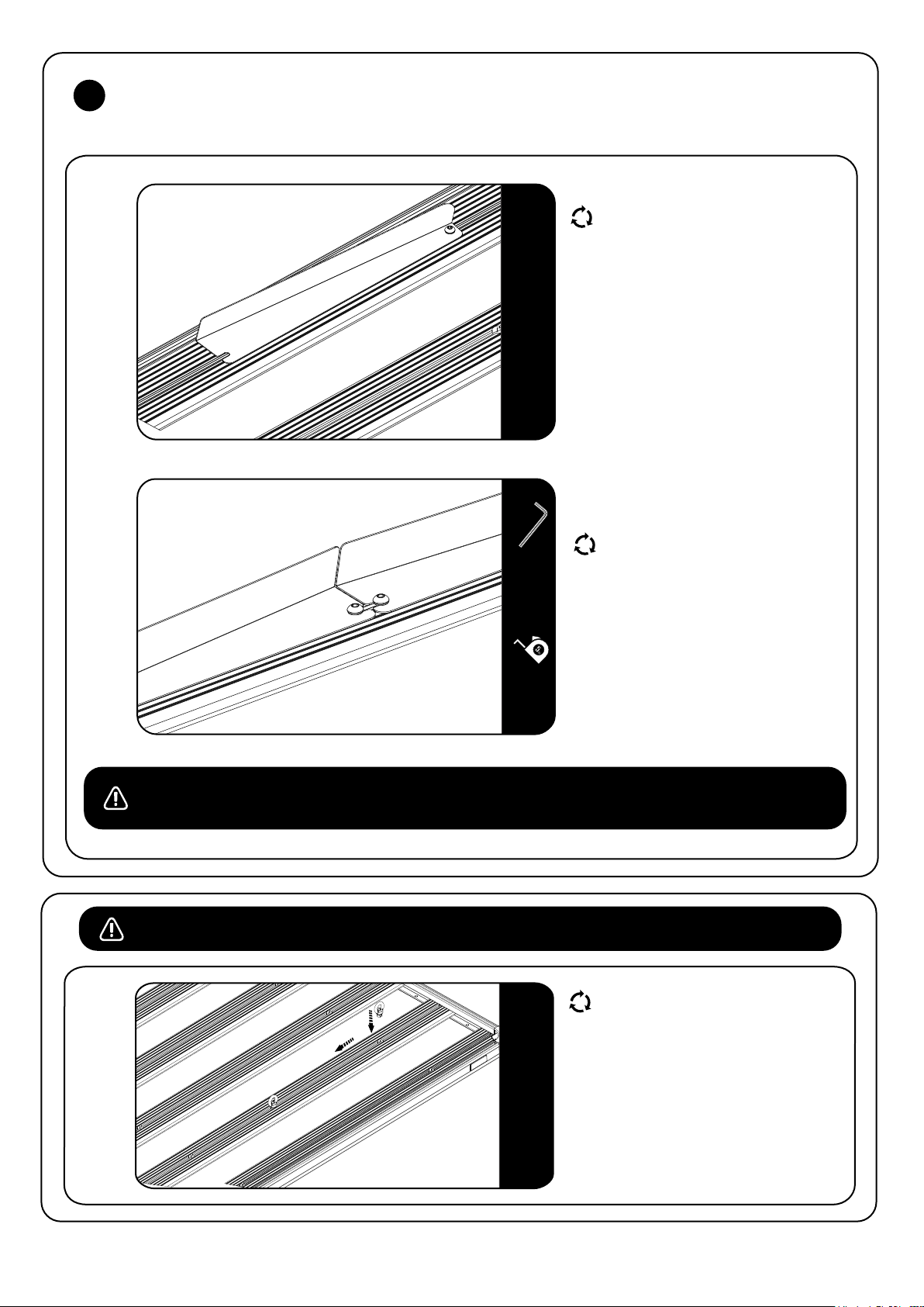
8
MONTAGE DES WINDABWEISERS
8.4
8.5
5 MM
Schiebe die zusammengesetzte Schraube,
die am Windabweiser befestigt ist, in die
T-Nut der Kombileiste (Abb. 8.4).
Die Schraube muss zur Seite des Slimline II
Dachträgers zeigen.
Wiederhole diesen Schritt für die andere
Hälfte des Windabweisers.
Schiebe beide Hälften des Windabweisers
bis zur Mitte der Kombileiste und richte
sie mittig zur Außenkante mit Hilfe eines
Maßbandes aus.
Setze nun die verbliebenen, zusammengesetzten Schrauben in die T-Nut ein, wie
auf Abb. 8.5 und ziehe sie mit einem
5 mm-Innensechskant fest.
HINWEIS: Sobald Du den Dachträger an Deinem Fahrzeug montiert hast, mach eine Probefahrt. Solltest Du laute
Windgeräusche festellen, versuche die Position der Windabweiser leicht zu verändern, indem Du sie 20 - 30 mm
auseinander ziehst.
HILFREICHER TIPP – VORHERIGE MONTAGE VON RINGSCHRAUBEN
Es ist hilfreich, wenn Ringschrauben
(RRAC012) am Dachträger vor der Montage
von zusätzlicher Ausrüstung bereits
vorhanden sind. Einfach die Ringschrauben
in die T-Nut auf den Leisten in der Mitte
befestigen und somit vorbereitet sein, falls
weitere Accessoires und Ausrüstung
montiert werden soll.
RRSTUNI
_REV_A05
8
© 2019 FRONT RUNNER OUTFITTERS
Page 18
9
LESE DIE FAHRZEUGSPEZIFISCHE MONTAGEANLEITUNG ZUR BEFESTIGUNG
9.1
10
EGAL, OB DU DEINEN DACHTRÄGER LIEBER SCHMUTZIG ODER SAUBER MAGST...
...Deine Ausrüstung wird Dir auch über Jahre viel Freude bereiten. Um die beste und dauerhafteste Funktionalität
des Dachträgers und insbesondere aller Öffnungen und beweglichen Teile zu gewährleisten, solltest Du Deiner
Ausrüstung hin und wieder eine kleine Pflege gönnen.
Nachdem Du die Plattform für Deinen Slimline II Dachträger montiert hast, lese Dir die Montageanleitung für Dein fahrzeug-
spezifisches Dachträger Kit durch und folge den Anweisungen zur Installation des Slimline II an Deinem Fahrzeug.
WIE DU DEINE FRONT RUNNER AUSRÜSTUNG PFLEGST
Spüle Deine Ausrüstung mit klarem Wasser und wische sie mit einem weichen Tuch ab. Bei hartnäckigem Schmutz
verwende eine weiche Bürste und etwas Seife.
Falls Du Deiner Ausrüstung etwas Gutes tun möchtest, kannst Du gerne etwas Wachs oder ein vor UV-Strahlung
schützendes Spray verwenden. Stelle nur sicher, dass das verwendete Wachs keine Polierkörnchen beinhaltet.
Im salzigen Küstenklima oder verschneiten Regionen, in denen Streusalz auf den Straßen genutzt wird, verwende
auf Silikonbasis beschaffenes Öl oder Spray, um die Muttern und Schrauben dauerhaft vor Korrosion zu schützen.
HOL DIR NOCH MEHR AUSRÜSTUNG VON FRONT RUNNER
11
Besuche uns Online auf www.FrontRunnerOutfitters.com
Markiere uns immer und überall! #FrontRunnerOutfitters #BornToRoam
Teile Deine Abenteuer auf:
RRSTUNI
_REV_A05
9
© 2019 FRONT RUNNER OUTFITTERS
Page 19
front runner
Instrucciones universales
para EL MONTAJE
de bacas portaequipaje Slimline II
ES
RRSTUNI
¡Léeme!
Gracias por comprar una baca portaequipaje Slimline II de Front Runner. Antes de empezar, tómese un momento para familiarizarse con las instruc-
ciones de instalación y los componentes recibidos. Consulte la página 2 para obtener una lista de todos los componentes, las cantidades y las
herramientas requeridas.
¡ADVERTENCIA IMPORTANTE!
ES FUNDAMENTAL QUE TODOS LOS PRODUCTOS DE FRONT RUNNER SE ENSAMBLEN DE FORMA ADECUADA Y SEGURA Y SE ADJUNTEN A SU VEHÍCULO. LA COLOCACIÓN
INADECUADA PODRÍA RESULTAR EN UN ACCIDENTE AUTOMOVILÍSTICO, Y PODRÍA CAUSAR LESIONES CORPORALES GRAVES O LA MUERTE. USTED ES RESPONSABLE DE
ENSAMBLAR Y ASEGURAR TODOS LOS PRODUCTOS FRONT RUNNER A SU VEHÍCULO, VERIFICAR LOS ACCESORIOS ANTES DE USARLOS E INSPECCIONAR PERIÓDICAMENTE
LOS PRODUCTOS PARA SU AJUSTE, DESGASTE Y DAÑOS. POR LO TANTO, DEBE LEER Y COMPRENDER TODAS LAS INSTRUCCIONES Y PRECAUCIONES SUMINISTRADAS CON
SU PRODUCTO FRONT RUNNER ANTES DE LA INSTALACIÓN O EL USO. SI USTED NO ENTIENDE TODAS LAS INSTRUCCIONES Y PRECAUCIONES, O SI NO TIENE EXPERIENCIA
MECÁNICA Y NO ESTÁ COMPLETAMENTE FAMILIARIZADO CON LOS PROCEDIMIENTOS DE INSTALACIÓN, DEBE DE INSTALAR EL PRODUCTO POR MEDIO DE UN INSTALADOR
PROFESIONAL U OTRO PERSONAL CAPACITADO.
Nota: Front Runner no será responsable de los daños causados por la imposibilidad de instalar el producto de acuerdo
con estas instrucciones. Por favor llámenos si tiene alguna pregunta sobre la instalación de este producto.
RRSTUNI
_REV_A05
1
© 2019 FRONT RUNNER VEHICLE OUTFITTERS
Page 20
ORGANÍZATE
1
Dependiendo del tamaño de baca portaequipaje Slimlime II ordenado, las cantidades mostradas pueden variar.
A continuación, es lo que se busca para RRSTUNI:
EN LA CAJA
1 32 X Tuerca Nyloc M8
2 4 X M8 x 45 Tornillo cabeza de botón
3 2 X Pieza de ensamble gruesa
4 2 X Pieza de ensamble delgada
5 4 X Perfil lateral
6 4 X Esquina
7 2 X Barra combinada
8 28 X M8 x 25 Tornillo cabeza de botón
9 12 X Barra estándar
10 4 X M6 x 12 Tornillo cabeza de botón
FIGURA 1.1
7
10
6
10
HERRAMIENTAS NECESARIAS
4mm
5mm
6
5
1
4
3
2
5
RRSTUNI
8
_REV_A05
8
9
2
9
7
5
2
© 2019 FRONT RUNNER VEHICLE OUTFITTERS
6
Page 21
2
MONTAJE DE BACA – PERFILES LATERALES
Nota: Omita este paso si su baca portaequipaje Slimline II es de 1560mm o más corta. Sólo tendrá dos perfiles
laterales y no es necesario el montaje.
Si usted ha recibido cuatro longitudes de perfil lateral (artículo 5), tendrá que unir las piezas juntas utilizando las piezas
de ensamble (artículos 3 & 4) para formar sólo dos longitudes siguiendo los sencillos pasos a continuación.
Con la excepción de la baca Slimline II de 2772mm de largo, las articulaciones del perfil lateral estarán diagonalmente
opuestas una vez que se haya montado la bandeja.
2.1
2.2
Canal de ranura en T
Canal en U
5
Agujero de ensamble
5
2
Los perfiles laterales se suministran en
pares. Tome un perfil de cada par, uno
corto y uno largo (excepto para la baca
Slimline II de 2772mm de largo, donde los p
erfiles laterales serán de igual longitud.
Aunque ambos pares tienen la misma
5MM
1
4
3
2
4MM
longitud, sigue siendo importante que
usted tome un perfil lateral de cada par).
Si nos fijamos en los perfiles laterales
se verá que en un extremo hay un agujero
que va a través de la parte superior e inferior
del canal "U".
(Consulte la imagen 2.1).
Estos son los agujeros de unión que va
a utilizar.
Inserte una ensamble grueso (punto 3) en
el canal "U" del perfil lateral alineando el
primer orificio con el orificio en el perfil
lateral como se muestra en 2.2.
Ahora coge un ensamble delgado (punto 4)
y tuerca nyloc (artículo 1). Deslice el
ensamble en la "ranura en T", seguido
de una tuerca nyloc. La tuerca nyloc debe
sentarse en la parte superior del ensamble
delgado con la "cúpula" de la tuerca nyloc
hacia arriba. Alinee el orificio exterior del
ensamble delgado y la tuerca nyloc con el
agujero de ensamble y apriete libremente
todo junto con un tornillo cabeza de botón
M8 x 45 (artículo 2) y una llave Allen
de 5mm.
Deslice el perfil lateral coincidente sobre las
dos piezas de ensamble, recordando insertar
una tuerca nyloc, y apriete una vez más
usando un tornillo cabeza de botón M8 x 45.
Repite los pasos anteriores para el otro lado.
RRSTUNI
_REV_A05
3
© 2019 FRONT RUNNER VEHICLE OUTFITTERS
Page 22
3
MONTAJE DE BACA – BARRAS COMBINADAS
3.1
Mire la barra combinada (artículo 7) y
Tuerca Nyloc
7
asegúrese de que haya una tuerca nyloc
insertada en cada bolsillo final mecanizado.
Si la tuerca nyloc se ha caído durante el
envío, insértala de nuevo en el bolsillo
como se muestra en la figura 3.1.
3.2
8
5MM
Gire la barra combinada (artículo 7) boca
abajo como se muestra. Deslice los perfiles
laterales (artículo 5) sobre la barra
combinada y alinee los agujeros. El orificio
final del perfil lateral debe alinearse con
el orificio en la barra combinada. Utilice un
cabeza de botón M8 x 25 (artículo 8) y
apriete ligeramente con una
llave Allen de 5mm.
7
5
RRSTUNI
_REV_A05
4
© 2019 FRONT RUNNER VEHICLE OUTFITTERS
Page 23
4
MONTAJE DE BACA - BARRAS ESTÁNDAR
4.1
Tome una barra estándar (artículo 9) y, al
igual que con la barra combinada, asegúrese
de que la tuerca Nyloc está en el bolsillo
del extremo mecanizado. Deslice la barra
8
Observe el orificio abierto
entre las barras
9MM
estándar entre los dos perfiles laterales
con la tuerca Nyloc en la parte inferior.
Posicione la barra de modo que el orificio
en la barra se alinee con el tercer orificio
en el perfil lateral como se muestra en la
figura 4.1.
Repita el proceso para las barras
estándar restantes asegurándose de que
hay un orificio abierto en el perfil lateral
entre cada barra. Refiera a la figura 1.1.
Utilice un tornillo cabeza de botón M8 x 25
(artículo 8) y fije ligeramente la barra
estándar al perfil lateral con una
llave Allen de 5mm.
5
6
MONTAJE DE BACA - BARRA COMBINADA
Revisión paso 3.1- a continuación, deslice la segunda barra combinada en los dos perfiles laterales
5.1
y fije de acuerdo a la figura 3.2.
MONTAJE DE BACA - TORNILLOS DE SUJECIÓN
RRSTUNI
Con su llave Allen de 5mm, apriete todos los tornillos cabeza de botón.
6.1
El ajuste de par recomendado para los tornillos cabeza de botón M8 es de 20 Nm o 15 ft lb.
_REV_A05
5
© 2019 FRONT RUNNER VEHICLE OUTFITTERS
Page 24
8
MONTAJE DE BACA - DEFLECTOR DE VIENTO
Nota: El deflector de viento debe estar montado en la parte delantera de la barra combinada. Si va a poner una pata
o pie en la barra combinada (recomendado), tendrá que deslizar el tornillo M8 utilizado para colocar estos en las
ranuras mecanizadas antes de ensamblar el deflector de viento.
9MM
8.1
8.2
Asegúrese de que la baca portaequipaje
Slimline II esté al revés. Consulte la etiqueta
del producto. Debe estar al revés como
5
4
2
se muestra.
Inserte dos tornillos cabeza de botón,
M8 medias tuercas y arandelas de
seguridad Schnorr (artículos 2, 4 & 5) en
la barra combinada como se muestra.
Deslícelo hacia el centro de la barra
combinada asegurándose de que la
arandela Schnorr está por encima del
canal ranura en T.
RRSTUNI
8.3
_REV_A05
5
4
3
2
7
Ensamble los elementos 2, 4 y 5 a ambos
deflectores de viento LH & RH (artículo 3)
como se muestra.
© 2019 FRONT RUNNER VEHICLE OUTFITTERS
Page 25
7
MONTAJE DE BACA -ESQUINAS
7.1
MONTAJE DE BACA - DEFLECTOR DE VIENTO 8
EN LA CAJA
Voltear la baca boca arriba.
10
4MM
6
Empuje la esquina en la posición como
se muestra, alineando el agujero en la
esquina con el Rivnut ya insertado en la
barra combinada. Utilice un tornillo cabeza
de botón M6 x 12 (artículo 10) y fije la
esquina en posición.
HERRAMIENTAS NECESARIAS
1 1 Baca portaequipaje Slimline II
2 4 M8 Tornillo medio
3 2 Deflector de viento (1LH + 1RH)
4 4 Arandela de seguridad Schnorr
5 4 M8 x 12 Tornillo cabeza de botón
FIGURA 1.2
2
5mm
4
5
3
1
RRSTUNI
_REV_A05
6
© 2019 FRONT RUNNER VEHICLE OUTFITTERS
Page 26
6
MONTAJE DE BACA - DEFLECTOR DE VIENTO
6.4
6.5
Inserte la tuerca montada en el deflector
de viento en el bolsillo combinado de la
ranura en T y deslícela hacia el costado
como se muestra en la figura 8.4. Repite
para la otra mitad del deflector de viento.
Centrar el deflector de viento en la baca y
mover los conjuntos de tornillos de la
figura 8.2 en las ranuras como se muestra
en la figura 8.5.
5MM
Nota: Una vez que el bastidor está montado en el vehículo, se recomienda hacer una prueba de manejo. En el supuesto
de que haya ruido excesivo del viento intente mover los dos deflectores ligeramente separados, dejando un
hueco de unos 20-30mm.
CONSEJO ÚTIL - ANILLOS DE AMARRE DE PRECARGA
Es de mucha utilidad el colocar los anillos
de amarre (RRAC012) en la baca
portaequipajes de Front Runner para su
uso futuro antes de colocar cualquier
accesorio.
Inserte los anillos de amarre por medio de
las ranuras y colóquelos en el centro de
la baca de techo.
RRSTUNI
_REV_A05
8
© 2019 FRONT RUNNER VEHICLE OUTFITTERS
Page 27
9
CONSULTE LA GUÍA DE INSTALACIÓN DE SU VEHÍCULO
9.1
10
LAS BACAS Y ACCESORIOS DE FRONT RUNNER SON MÁS FELICES CUBIERTOS DE LODO
Pero para poder mantener la funcionalidad completa de las ranuras de la baca y las partes móviles, es posible que desee dar a
su equipo un baño de vez en cuando.
¡Es fácil! Cuida tu equipo Front Runner de la misma manera que haces con el exterior de tu vehículo:
Ahora que su baca portaequipaje Slimline II está montada, obtenga la guía de instalación del juego de baca y siga las
instrucciones para ajustar la Slimline II a su vehículo específico.
CÓMO CUIDAR DE SU EQUIPO FRONT RUNNER
Enjuague con agua limpia y limpie con un paño suave y seco. Para manchas persistentes, usa un cepillo suave
y un jabón suave.
Si realmente quieres cuidar tu equipo, puedes encerar ligeramente las superficies o utiliza un aerosol protectivo con
inhibidores para rayos solares UV. Solo asegurate de no utilizar ceras compuestas que contienen abrasivos.
En climas costeros salados, o regiones nevadas donde la sal se utiliza para despejar las carreteras, aplicar un
aceite o aerosol basado en silicona en tuercas y tornillos ayudará a prevenir la corrosión.
¡YA SEA QUE TE GUSTE RODAR SUCIO O LIMPIO, SU EQUIPO FRONT RUNNER LE DARÁ MUCHOS AÑOS DE SERVICIO!
11
INSTALAR OTROS ACCESORIOS PARA EL VEHÍCULO Y DE BACA
Ahora es el momento de visitar su distribuidor favorito de Front Runner en persona o en línea.
Asegúrate de etiquetarnos. ¡Nos encanta ver nuestro equipo en acción!
#FrontRunnerOutfitters #BornToRoam
Comparte tus aventuras en:
RRSTUNI
_REV_A05
9
© 2019 FRONT RUNNER VEHICLE OUTFITTERS
 Loading...