

Page 1
IR Speaker Installation Instructions
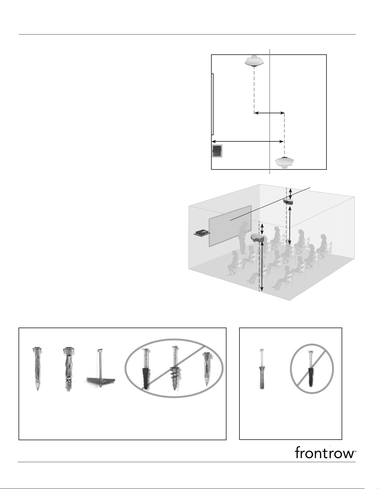
classroom centerline
IMPORTANT INFORMATION
1. Speakers should only be placed on the side walls of
the classroom.
2. Walls should have a space approximately 10 in. wide by
5 in. tall (25 x 13 cm) to solidly mount the wall bracket.
3. If the room has drop lighting, the speaker should be
placed just below the bottom of the lights.
4. DO NOT
5. DO NOT
6. DO NOT use a splitter or adaptor with cables.
shorten sensor cables.
lengthen cables.
INSTALLATION DIMENSIONS
A Speakers should be 3 to 6ft. (1 to 2m) apart,
CENTER TO CENTER. NOTE: Do NOT place
directly opposite each other
B Speaker on same side of room as 940R should
be farthest from receiver
C Speakers should be mounted between 7.5 to 10ft
(2.3 to 3m) from the floor
D Speakers should be mounted at least 5in (13cm)
from the ceiling
A
B
D
C
D
C
Use the recommended fasteners to mount your speakers. If the recommended fasteners cannot be
used, any alternate fastener must be rated to support 60 lbs or more.
Drywall*
YES YES YES NO NO NO
Hollow Wall
Anchor
#6 x 2in min.
*Recommended fasteners
© 2008 Phonic Ear Inc. Phonic Ear, FrontRow and the names of Phonic Ear and FrontRow products are trademarks or registered trademarks of Phonic Ear Inc. in the U.S. and other countries. 821-2856-103/Rev. B 0808
Hollow Wall
Anchor
#10 x 2in min.
Toggle Bolt
Anchor
#6 x 2in min.
Plastic
Shield
Anchor
Threaded
Wall
Anchor
Hollow
Wall Anchor
#6 x 1.75in.
Concrete/Cinderblock/Brick*
YES
Lead
Shield Anchor
#8 x 1.5in.
NO
Plastic
Shield
Anchor
Page 2
IR Speaker Installation Instructions (cont'd)
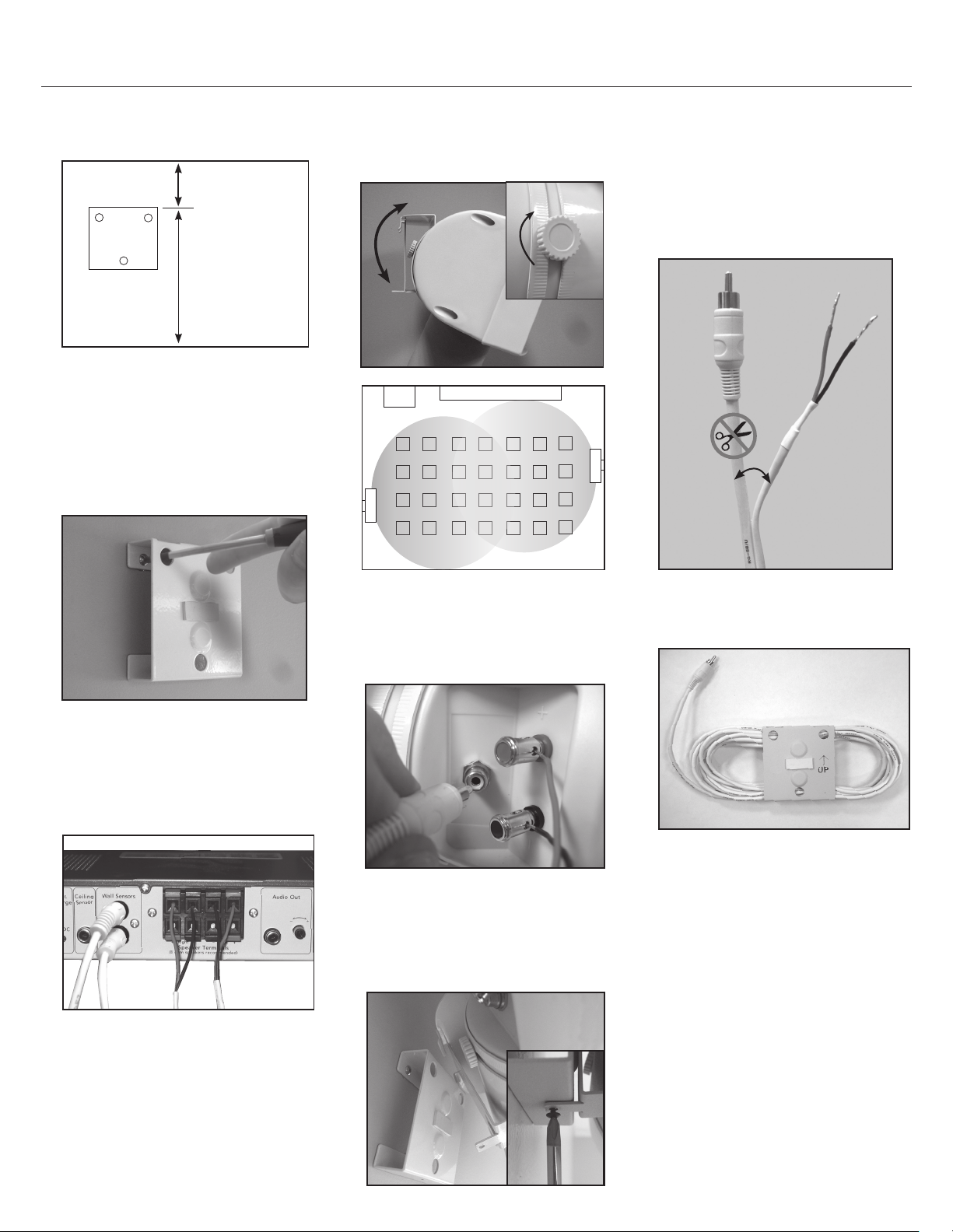
1. Mark drill holes using template from
speaker box
ceiling
floor
5in. (13cm) min.
height from ceiling
7.5 to 10ft
(2.3 to 3.0m)
2. Mount wall plate
NOTE: Use the recommended
fasteners for your wall type. If the
recommended fasteners cannot be
used, any alternate fastener must
be rated to support 60 lbs or more.
5. Angle speaker toward the center of
the closest half of the classroom.
Tighten knob.
940R
speaker
chalkboard
speaker
TRIMMING COMBO CABLE
1. Measure combo cable to length.
2. Split combo cable and cut speaker
cable ONLY.
DO NOT cut sensor cable.
Sensor
Cable
Speaker
Cable
3. Attach cables to receiver
NOTE: Remember to connect one
speaker to the LEFT channel and
one to the RIGHT channel.
Classroom top view
3. Coil excess sensor cable and place
in wall plate.
6. Attach cables
7. Attach speaker to wall plate and
install set screw.
4. Run cable to speaker locations
NOTE: The cable is UL listed. If
there is any excess cable, it can be
safely stored in the plenum space.
If there is no plenum space see
instructions, "TRIMMING COMBO
CABLE" at right.
 Loading...