

Page 1
CMBT Bluetooth® Audio Receiver
Installation Guide
Installation with ezRoom ICR-01 Smart Receiver, CM3000 amplifier/controller,
or CM800Si amplifier
CMBT
CB55A shown
(CB55G and CB55I also available)
ICR-01
1. Most ICR-01, CM3000, and CM80 0Si installations house the components in an
enclosure. The CMBT Bluetooth audio receiver works only in RF-friendly enclosures
like the CMPL2 with plastic lid. Ensure that your enclosure meets this requirement
before proceeding.
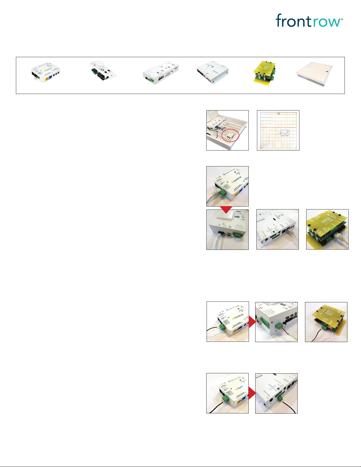
2. You can secure the CMBT receiver either to the metal enclosure mounting plate using
the supplied mounting screws, or to the plastic lid using PT screws only (3.5 x 10mm /
#6 x 3/8in). If mounting to the lid, ensure that CMBT receiver is installed in an area that will
not interfere with other components when the lid is closed. ( Image 1)
3. Plug the supplied UTP cable into the Intercom Port of the CMBT, and connec t
the other end to the Intercom port of the ICR-01, CM30 00, or CM800Si. (Image 2)
This will supply power to the CMBT.
NOTE: If a device is already connected to the Intercom port of the ICR- 01, CM30 00, or
CM800Si, proceed as follows:
a. If the device is a CB85 ceiling mic, unplug it from the amplifier and reconnect it to
the Intercom Mic (CB85) por t on the CMBT.
b. If the device is a CB75 wall mic with volume control, you can either leave it connected
to the amplifier, and power the CMBT separately using a dedicated power supply or
using a 5V patch cord from the amplifier (ICR-01 only) unplug it and consider installing
a CB85 ceiling mic and CB55 volume/pairing control instead (see Step 4b below)
c. If the device is a CB50 volume control, unplug it and consider installing a CB55
volume/pairing control instead (see Step 4b below)
CM3000
Image 1
Image 2
OR
OR
CM800Si
CMPL2
OR
4. Decide how you want to remotely initiate Bluetooth pairing:
a. If you are using a CB60 00 touch control panel, we recommend initiating pairing
from the touch screen:
a.1. Program Bluetooth pairing buttons for your CB600 0 touch controller following
the instructions in the CB6000 Installer Guide
a.2. If you are using the ICR-01 Smart Receiver or CM800Si amp:
a.ii. Locate the supplied relay cable and connec t the white/neutral wire to the
GND connec tor on the Ext Control terminal of the CMBT and connect
the other end to the COM connector on one of the Relay terminals of
the ICR- 01 or to the R1-COM terminal of the CM800Si. (Image 3)
a.ii. Connect the black/hot wire of the relay cable to the Relay connector
on the Ext Control terminal of the CMBT and connect the other end to
the NO connector on one of the Relay terminals of the ICR-01 or to the
R1-NO terminal of the CM800Si. (Image 3)
a.3. If you are using the CM3000 amp:
a.iii. Locate the supplied infrared interface cable and connect the white/neutral
wire to the GND connec tor on the Ext Control terminal of the CMBT
and connect the other end to the IR- connector on the IR terminal of the
CM3000. (Image 4)
a.iii. Connect the black/hot wire of the interface cable to the IR In connector
on the Ext Control terminal of the CMBT and connect the other end to
the IR+ connector on the IR terminal of the CM3000. (Image 4)
Installation instructions continued on back side...
Image 3
OR
Image 4
© 2 018 FrontRow C alyp so LLC Pho nic Ear, Fron tRow, Cal ypso a nd the nam es of Pho nic Ear, Cal ypso, a nd Front Row prod uct s are tra demar ks or registered trademarks of
FrontRo w Calyp so LLC in the U.S. and ot her countrie s. Bluet ooth is a re gistered tra demark of Bluet ooth SIG , Inc.
1530- 00016/Rev A 0718
Page 2
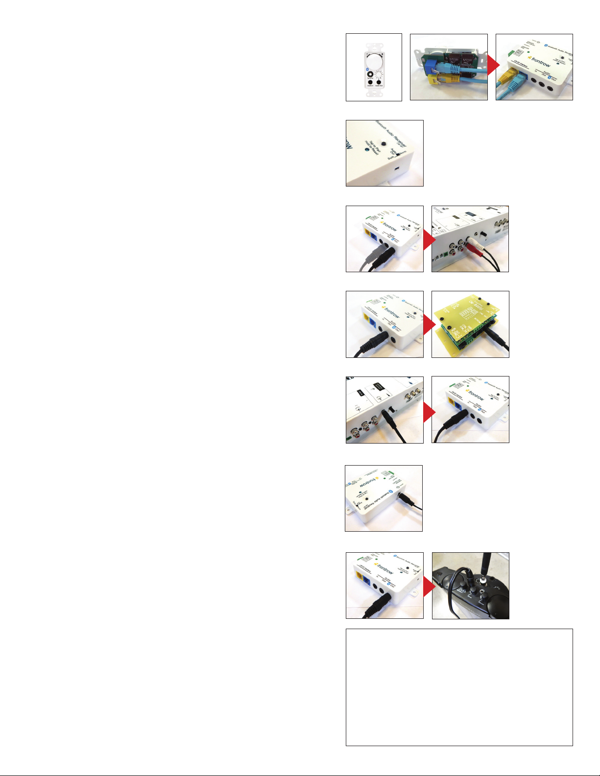
b. The CB55 is a wall mount accessory for the CMBT. It provides the user with easy
access for Bluetooth pairing, as well as, volume control and line audio in/out
for lessson capture. The CB55 cannot be used on its own.
b.1. Install a single-gang electrical box, sur face box, or mud ring according to the
manufacturer’s instructions.
b.2. Locate the UTP cable with blue ends supplied with the CB55 kit. Feed the cable
through the electrical box to the location of your CMBT. Ensure the cable is
installed in compliance with your national and local electrical code. Connec t one
end to the blue jack on the CB55 and the other end to the blue CB-55 Interface
jack on the CMBT receiver. (Image 5)
b.3. Locate the UTP cable with yellow ends supplied with the CB55 kit. Feed the
cable through the electrical box to the location of your CMBT. Ensure the cable
is installed in compliance with your national and local electrical code. Connect
one end to the yellow jack on the CB55 and the other end to the yellow CB-55
Interface jack on the CMBT receiver. (Image 5)
b.4. Screw the CB55 into the electrical box and attach the supplied Decora faceplate.
b.5. Follow the instructions for programming the behavior of the CB55 knob using located
in the Installer Guide for your amplifier (ICR- 01, CM3000, or CM800SI)
5. Set the Audio Out summing switch as follows:
a. If you are using the CB55 volume/pairing control (see Step 4b) AND the CM80 0Si or other
amplifier with only one available audio input jack, select Sum (Image 6). This will sum the
audio from Bluetooth sources with audio from the CB55 before passing to the amplifier.
b. For all other situations, select the Norm position.
Image 5
CB55 Fron t
Image 6
Image 7
Image 8
CB55 Bac k
6. Connect audio cables as follows:
a. If you are using the ICR-01 Smar t Receiver or CM30 00 AND have selected the Norm
position in Step 5 above, plug one of the supplied 3.5mm audio cables into the
Bluetooth Audio Out jack on the CMBT and connect the other end to one of the
available audio inputs on the ICR-01 Smart Receiver or CM3000. (Image 7)
b. If you are using the ICR-01 Smar t Receiver or CM30 00 AND are using the CB55 —
OR have selected the Sum position in Step 5 above — plug another of the supplied
3.5mm audio cables into the Audio Out jack on the CMBT and connect the other end
to an available audio input on the ICR-01 Smart Receiver or CM3000.
c. If you are using the CM800Si, plug the summing 3.5mm audio cable into the Audio Out
jack on the CMBT (TRS) and connect the other end to the audio input on the CM800Si (TS).
(Image 8)
7. If you are using the CB55, plug another of the supplied 3.5mm audio cables into the
External ALD Out (or Line Out) jack of the ICR-01 Smart Receiver, CM3000, or CM800Si
and connect the other end to the Audio In jack on the CMBT. (Image 9)
Installation with Pro Digital 940R or ToGo 925RS receiver/amplifiers
1. Attach the supplied rubber feet to the bottom of the CMBT receiver and select a stable
space near the 940R or 925RS
2. Provide a power source for the CMBT:
a. If using the Pro Digital 940R, ToGo 925RS or other amplifier, connect the supplied
power supply to the 5VDC jack of the CMBT and plug the supply into an
electrical outlet. (Image 10)
3. Plug one of the supplied 3.5mm audio cables into the Bluetooth Audio Out jack
on the CMBT and connect the other end to one of the available audio input s on the
940R (3.5mm to RCA) or 925RS (3.5mm summing cable) ( I mag e 11) .
Testing your installation
1. Power up your amplifier/receiver system
2. Initiate pairing mode by pressing the Bluetooth pairing button on:
The CB55 volume/pairing control or The CB600 0 touch control panel or
The CMBT Bluetooth audio receiver
3. Go to the Bluetooth settings on your source device and select CMBTxxx x
4. We suggest initially setting the volume on the source device to ¾ full scale
5. Play some audio
6. Adjust levels as needed on the source device and/or the FrontRow system
Image 9
Imag e 10
Im ag e 11
Bluetooth Specifications
Standard: Bluetooth 4.1
Frequency Range: 2402-2480 MHz
Maximum RF Power: +4dBm
Declaration of Conformity
Hereby, FrontRow C alypso, LLC declares that the radio equipment type,
Juno Tower receiver with Bluetooth, model number ITR-02 is in compliance
with Directive 2014/53/EU.
Visit https://www.gofrontrow.com/sites/default/files/how-to/
classroom-audio-juno-itr-02-declaration-of-conformity.pdf or the
full tex t of the EU Declaration of Conformity.
1530- 00016/Rev A 0718
 Loading...