

Page 1
CB2000
INSTALLER GUIDE
Page 2

YOU’RE ABOUT TO MAKE
LEARNING MORE ACCESSIBLE
Welcome to FrontRow — the teacher- and tech-friendly way to improve the learning environment in every classroom.
To make your installation of the FrontRow CB2000 as efficient as possible, we recommend that you first read the section
in this guide called Before You Begin, and from there proceed to Steps 1 through 6.
If you follow the steps set out in this Installer Guide and organize everything you need beforehand, you’ll find setting up
your FrontRow CB2000 touch control panel to be quite simple. Of course, if you run into any obstacles, you can always find
contact information for our technical support representatives at www.gofrontrow.com.
Thank you for choosing FrontRow! You're just steps away from a more productive classroom.
Page 3

CONTENTS
Step 1................................................................................Pages 1-6
Before You Begin
Step 2...................................................................................Page 7
Get Your Configuration Files
Step 3..................................................................................Pages 8
Set-Up
Step 4................................................................................Page 9-14
Configuring Your CB2000s
Step 5..................................................................................Page 15
Physical Installation Prep
Step 6..................................................................................Page 16
Plan your Installation
Step 7...............................................................................Page 17-19
Install your CB2000
Appendix A ..........................................................................Page 20-27
Control Logic Programming
Appendix B ......................................................................... Pages 28-32
Setting Preferences
Appendix C.............................................................................Page 33
CM3000 Commands
Appendix D.............................................................................Page 34
CA1000 Commands
Appendix E .............................................................................Page 35
Pin-Out Guide
Appendix F .............................................................................Page 36
Troubleshooting
Read Me
Be sure to read the helpful tip boxes found throughout this guide. Of
course, if you need further assistance, you can always call us at one of the
numbers found on the back page.
Page 4
Step 1:
Make sure you’ve got everything you need to install your Frontrow CB2000s. By taking the time to prepare,
you’ll help ensure the actual set-up is as quick and problem-free as possible.
Before you begin
1. Visualize your goal
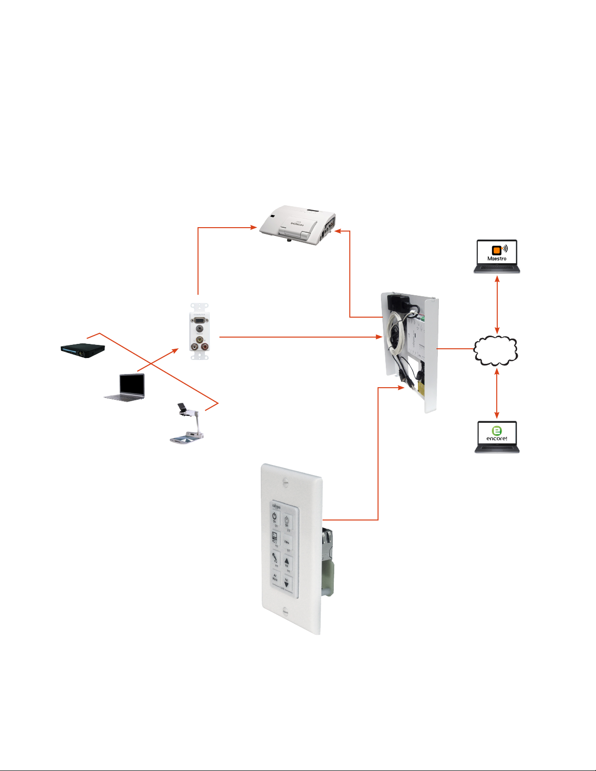
When your Frontrow system CB2000 is installed, it may look something like this:
Projector
Video
Control
Audio
DVD Player
WP-PCAV
LAN
Computer
Document
Camera
ezRoom
Wall Box
Control
CB2000
Control your projector, audio
and other devices.
1
Page 5
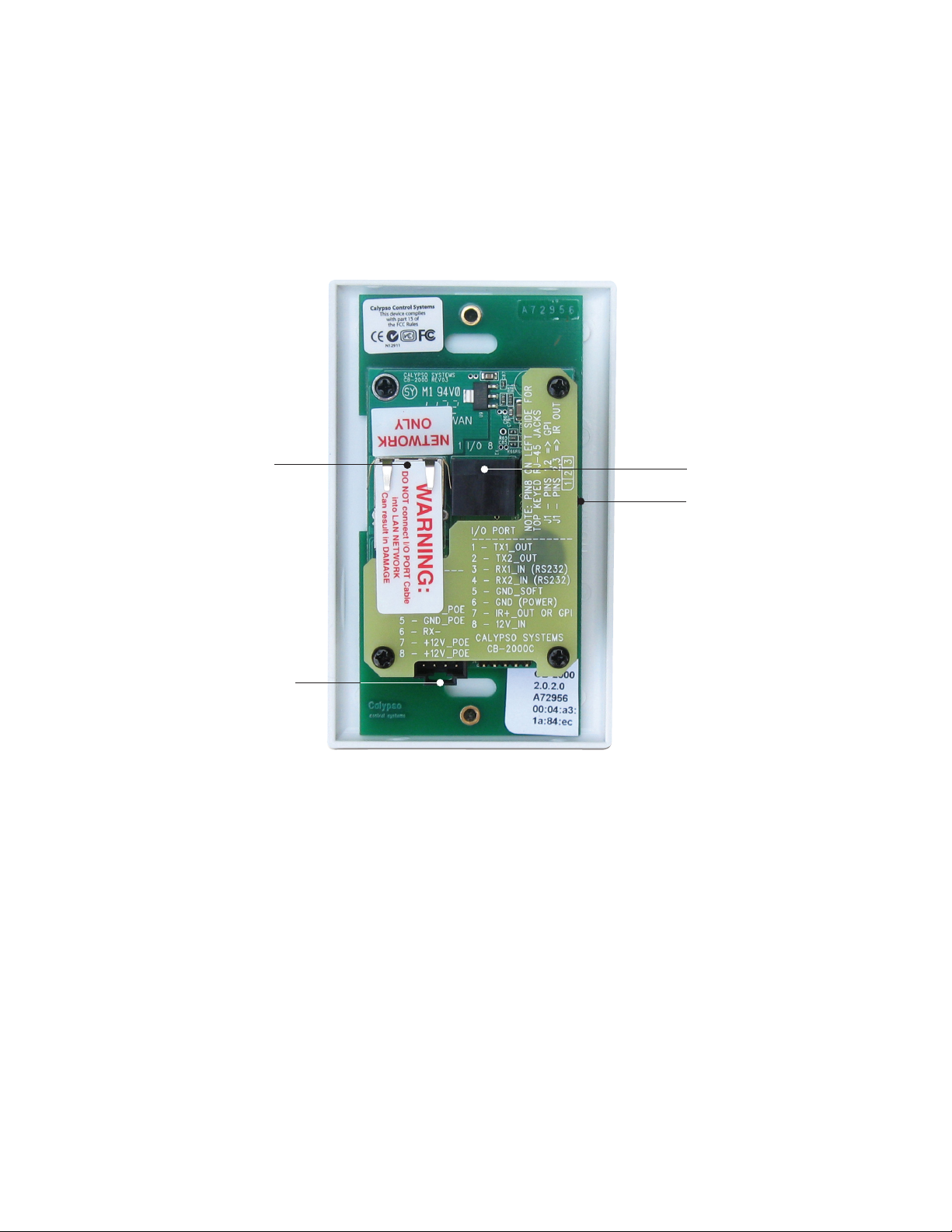
2. Get familiar with the button panel
Back of CB2000
Network jack
CB50 Volume
Control Connector
AUX jack
Jumper for switching
between IR out or GPI
(on TB14 or TB6+TB8)
2
Page 6
3. What do you want to control? How do you want to control it?
Your CB2000 can let teachers control or communicate with practically any device or person. Now is the time to
plan what you want to do.
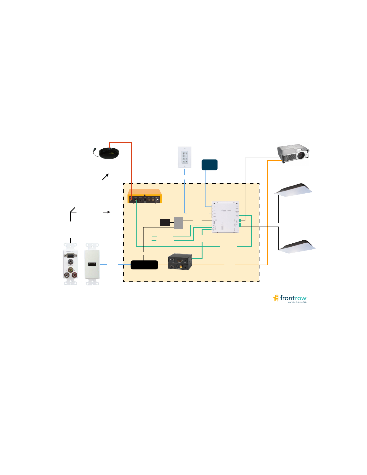
Example 1: Typical ezRoom setup with projector
In this example, the CB2000 works with other ezRoom components to turn a projector on and off, switch
inputs, handle the transport controls for a DVD player, and control audio volume from the teacher’s computer,
an MP3 player, and two FrontRow wireless microphones. If FrontRow Conductor™ is being used in the school,
the CB2000 could also initiate intercom calls and trigger alerts.
ezRoom Wiring
VGA & video to projector
Audio to ezRoom
AV Cable
Mic dome receiver
CAT5e
+12VDC
HDMI Receiver
+12V
PC Audio
RCA Audio
CB2000
CAT5e
TB14
+5V
HDMI Audio
Extractor
LAN
CM3000
Network +12V
+12V
HDMI
Audio
INSIDE OF THE ENCLOSURE
Projector
Serial
Speaker
Mic Audio
Speaker
HDMI
3
Page 7
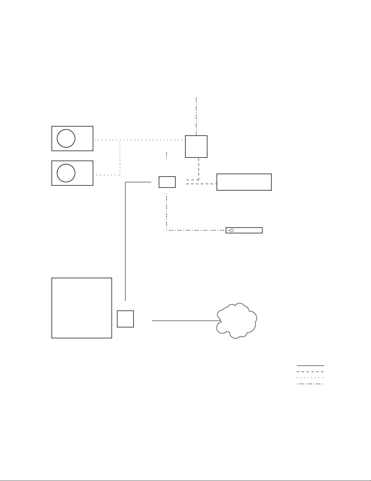
Example 2: Using CB2000 as a stand-alone controller with TB14
You can also use the CB2000 as a stand-alone serial controller. In this configuration, the FrontRow TB14 adapter
included with your CB2000 standalone kit supplies power, routes commands, and feeds data back (in the case
of bidirectional serial devices). In combination with powerful tools like FrontRow Maestro™, this can allow you to
‘network’ and manage projectors that are otherwise not online. Below are the basic connections for controlling a
projector and amplifier serially, and a DVD player via infrared remote.
Power
Speaker
Speaker
Control + power
AUX
NETWORK
TB14
AUX
Power
POWER IN
IR
IR
Serial Controlled
Amplifier
RS232
RS232
Projector
DVD
Player
CB2000
Screen or interactive
white board
Control
Panel
NOTE: This is a schematic illustration
intended to clarify the relationship of
components to each other. The location
of jacks shown here may not reflect their
true position on specific devices.
LAN
Cat 5 cable
Serial cable
Speaker cable
Other cable
4
Page 8
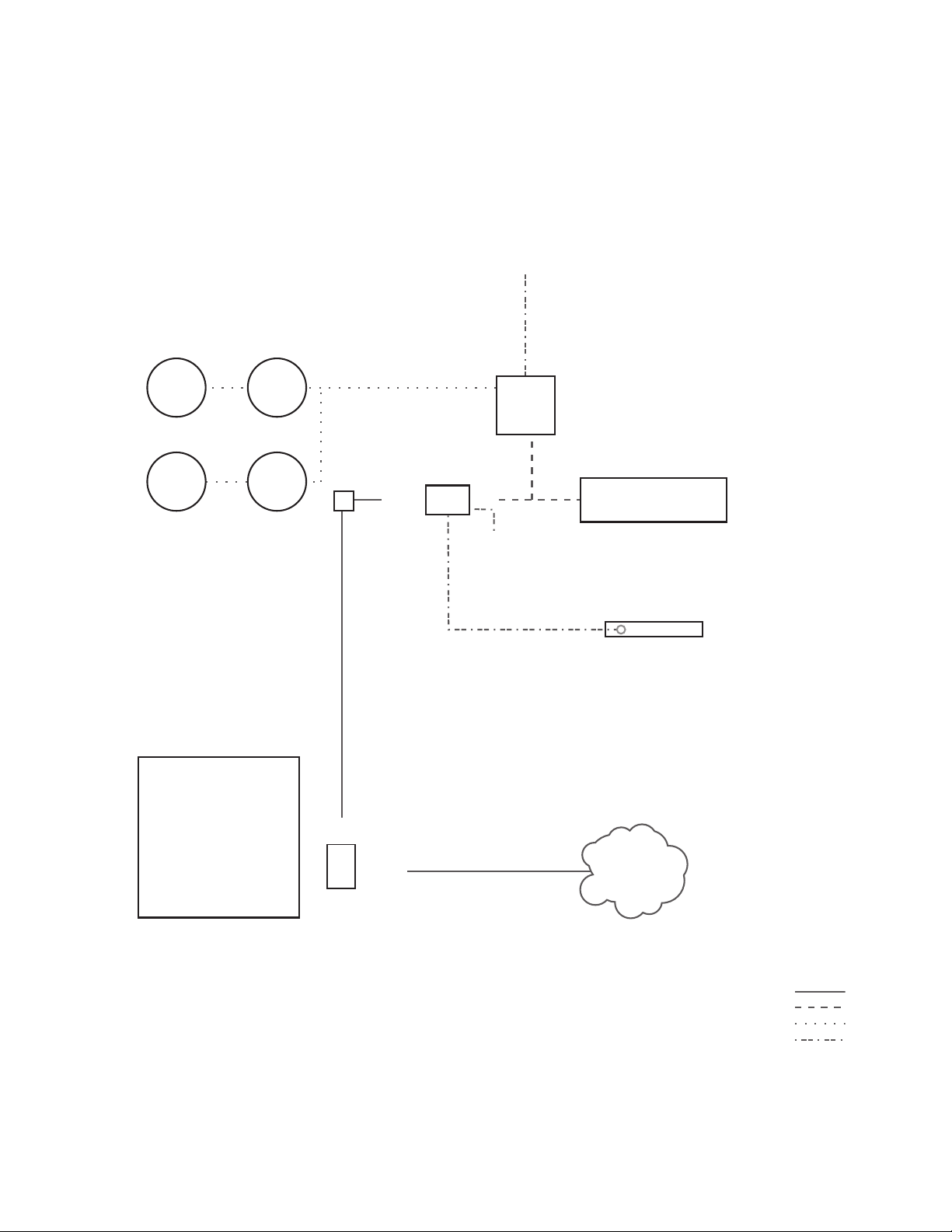
Example 3: Using CB2000 as a stand-alone controller with TB6 and TB8
You can use the CB2000 as a stand-alone serial controller with the TB6 and TB8 terminal blocks. In this configuration,
the FrontRow TB6 and TB8 adapters included with your CB2000 standalone kit supply power, routes commands, and
feeds data back (in the case of bidirectional serial devices). In combination with powerful tools like FrontRow Maestro™,
this can allow you to ‘network’ and manage projectors that are otherwise not online. Below are the basic connections
for controlling a projector and amplifier serially, and a DVD player via infrared remote.
Power
Third party
serial
SpeakerSpeaker
amplifier
Speaker Speaker
Screen or interactive
white board
TB8
Control + power
AUX
CB2000
Control
Panel
PWR/GND
NETWORK
TB6
IR
IR
RS232
Power
RS232
Projector
DVD
Player
LAN
NOTE: This is a schematic illustration
intended to clarify the relationship of
components to each other. The location
of jacks shown here may not reflect their
true position on specific devices.
Cat 5 cable
Serial cable
Speaker cable
Other cable
5
Page 9
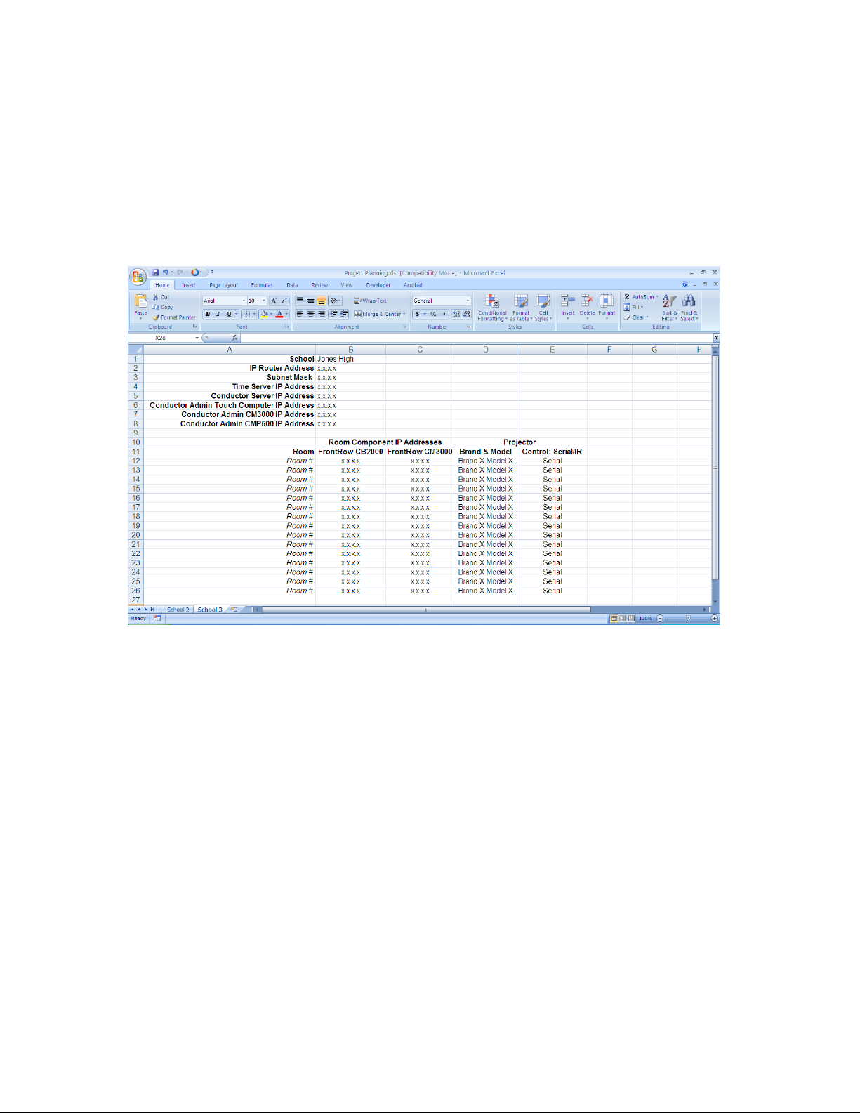
4. Gathering information
You will save a lot of time by working with the school to:
• Make a list of all rooms to be outfitted and the equipment to be controlled in each
• Set aside IP addresses for each CB2000, CM3000, and any other FrontRow components or servers
To help organize this important information, we have an ezRoom Installer Planning Template available for
you to download at www.gofrontrow.com/products/ezroom under the Resources tab. Of course, you can
also create your own. It should look something like this:
6
Page 10

Step 2:
Your CB2000s need a script to tell them what the buttons should do, what other devices they need to communicate with, and how. If your configuration — the collection of commands you want to issue from the CB2000 and the
devices you want to control — is the same in each room in your installation, then you will need only one configuration
base file which you will modify with specific IP addresses unique to each room. If the situation is different from room
to room, you will need different base files that are tailored to each configuration.
There are several ways to create your configuration files:
• Go to www.gofrontrow.com/products/ezroom and find the Base Configuration File library under the Resources
tab. Each Base Configuration File stored here includes both the user interface and control logic programming
needed for the most common applications. Note that if you are using the CB50 volume control as part of your
installation, you will need the CB2050 configuration files.
• If your configuration is uncommon enough that it’s outside the scope of the Base Configuration File library, and
you have some basic familiarity with programming, you can easily build your own user interface designs or
control logic programming. See Appendices A, B, and C for a detailed description of how to do this.
Getting Your Configuration Files
7
Page 11
Step 3:
Set-Up
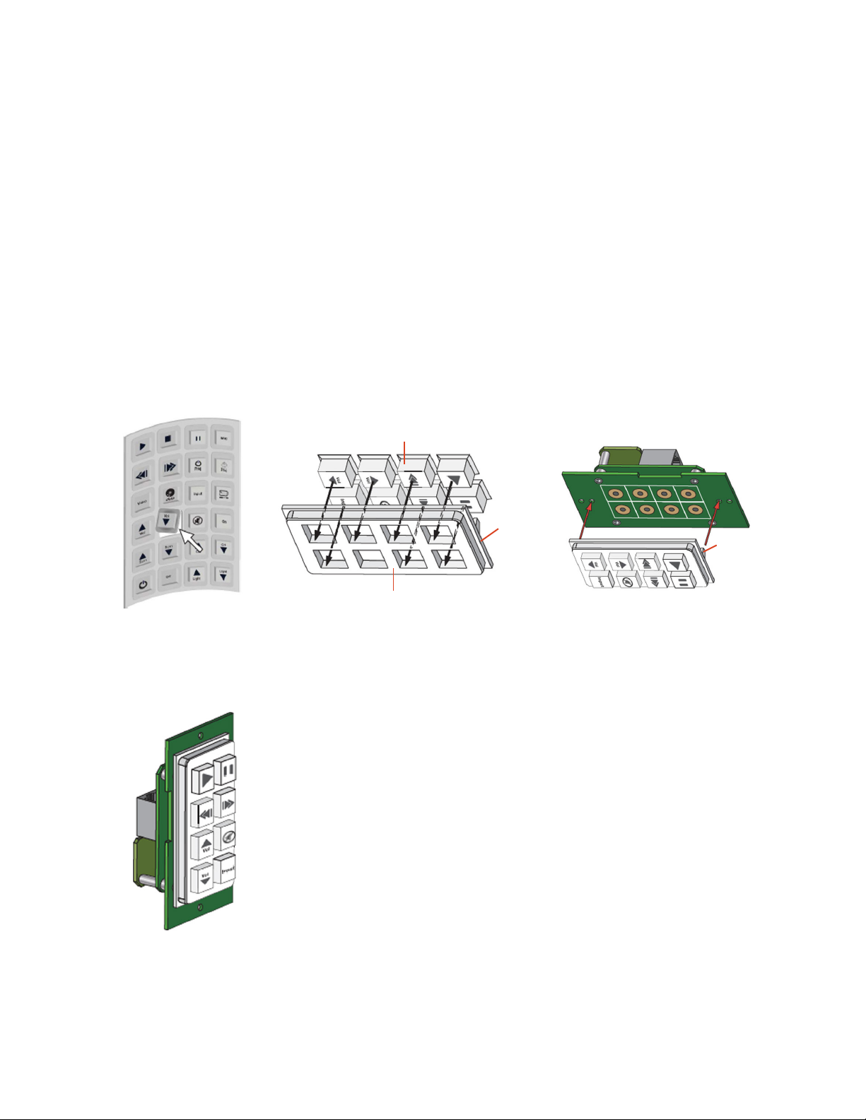
Assembling the Button Pad
• The CB2000 comes with a set of 24 tactile, pre-labeled button “caps”. Choose eight buttons for
assembling the button pad.
• Carefully tear away the perforated edge from the button sheet for each button. Arrange them in the
array desired. Keep in mind that the button locations shown below will correspond to specific numbered events
(1-8) that are programmed in your configuration file (see Step 2 and Appendix A).
• Orient the plastic button holder so that the backside is facing up. Place the buttons face down into the holder in
the preferred order. Assure the button orientation is correct.
• Align the CB2000’s two holes with the plastic snaps on the button holder and snap together.
Individual buttons
CB2000
Back side
facing up
Plastic snap
Plastic button holder
The assembly is now complete and should look like the depiction illustrated below (buttons may vary).
It is now ready for powering up and configuration.
8
Page 12

Step 4:
Configuring Your CB2000s
Estimated time for this step: 5-10 minutes per CB2000
Here’s where you wake up your CB2000s and let them know what their mission is. You can of course reconfigure
them at any point if your setup changes or you make a mistake — but it’s best to plan ahead so that you don’t have
to (see Step 1).
For greatest efficiency, we recommend configuring your CB2000s all at once in the office prior to going to the
installation site, but you can also do it room by room at the school if you prefer.
1. Gather your configuration tools
To configure your CB2000s, you will need to collect:
• Your CB2000s
• Any of the following power sources:
• 1 FrontRow CM3000 amplifier/switch with power supply (included in most full ezRoom systems); or
• 1 FrontRow TB14 adapter with power supply; or
• 1 FrontRow TB6 and 1 FrontRow TB8 adapter with power supply
• 2 lengths of Cat 5 cable (NOTE: Some older computers may require you to use a cross-over network cable. If you
cannot detect the CB2000 in your browser after following the connection instructions, try using a cross-over cable.)
• A computer with RJ45 connection and a web browser installed
• A completed ezRoom Installer Planning Template or other detailed information about the school’s available IP
addresses for your CB2000s, CM3000s, and other components (see Step 1)
• Your Base Configuration File(s) (see Step 2)
• Masking tape or labels and a marker
2. Connect your configuration setup
Take your first CB2000 and connect it to your configuration equipment in either of the ways shown here:
a. With CM3000 as power source
WARNING: TO AVOID DAMAGE TO THE DEVICE, IN THIS CONFIGURATION
CONNECT THE CM3000 TO THE CB2000’S ‘NETWORK ONLY’ JACK!
Power
12VDC
NETWORK CLAN3 LAN1 NETWORK
CB2000
Control
Panel
NOTE: This is a schematic illustration
intended to clarify the relationship of
components to each other. The location
of jacks shown here may not reflect their
true position on specific devices.
CM3000
Amplifier/Switch
Computer
Cat 5 cable
Other cable
9
Page 13
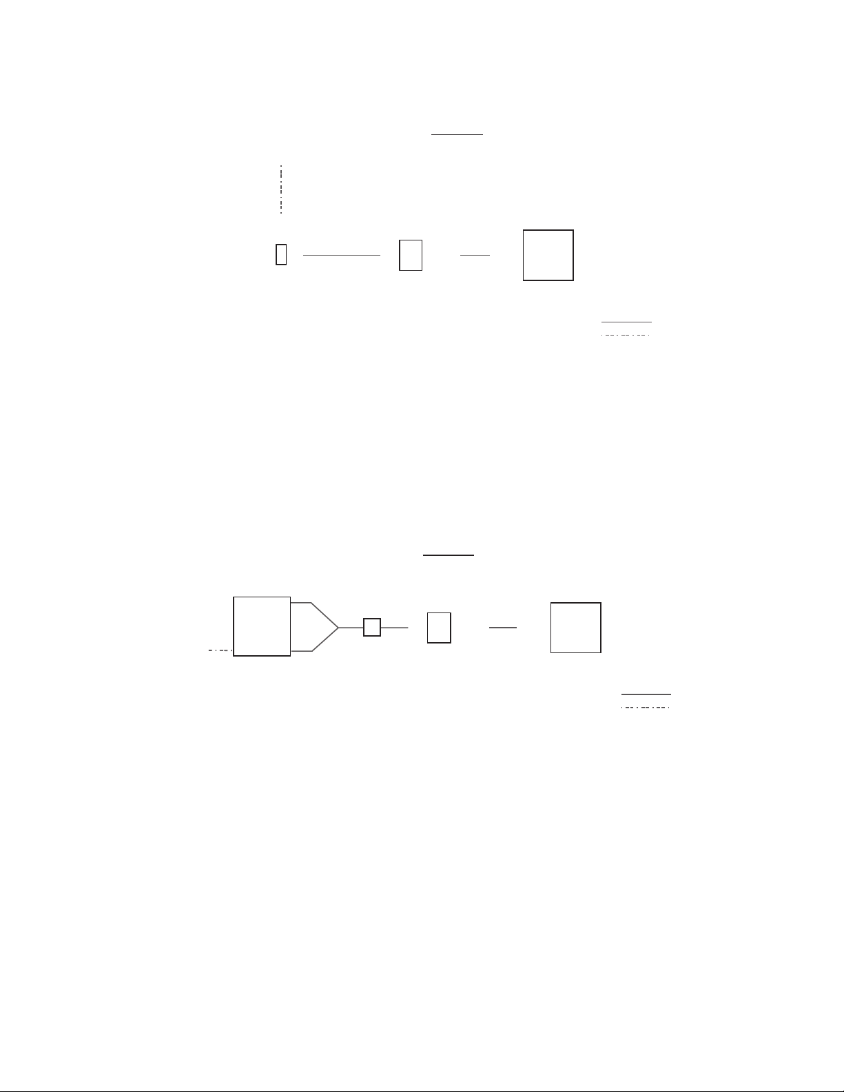
b. With TB14 as power source
WARNING: TO AVOID DAMAGE TO THE DEVICE, IN THIS CONFIGURATION
CONNECT THE TB14 TO THE CB2000’S ‘AUX’ JACK!
Power
POWER IN
AUX
AUX NETWORK NETWORK
TB14
Adapter
CB2000
Control
Panel
Computer
Cat 5 cable
Other cable
NOTE: This is a schematic illustration
intended to clarify the relationship of
components to each other. The location
of jacks shown here may not reflect their
true position on specific devices.
c. With TB6/TB8 as power source
WARNING: TO AVOID DAMAGE TO THE DEVICE, IN THIS CONFIGURATION
CONNECT THE TB8 TO THE CB2000’S ‘AUX’ JACK!
GREEN
PWR
AUX NETWORK NETWORK
Power
PWB
TB6 Adapter
GND
YELLOW
TB8
Adapter
CB 2000
Control
Panel
Computer
Cat 5 cable
Other cable
NOTE: This is a schematic illustration
intended to clarify the relationship of
components to each other. The location
of jacks shown here may not reflect their
true position on specific devices.
10
Page 14
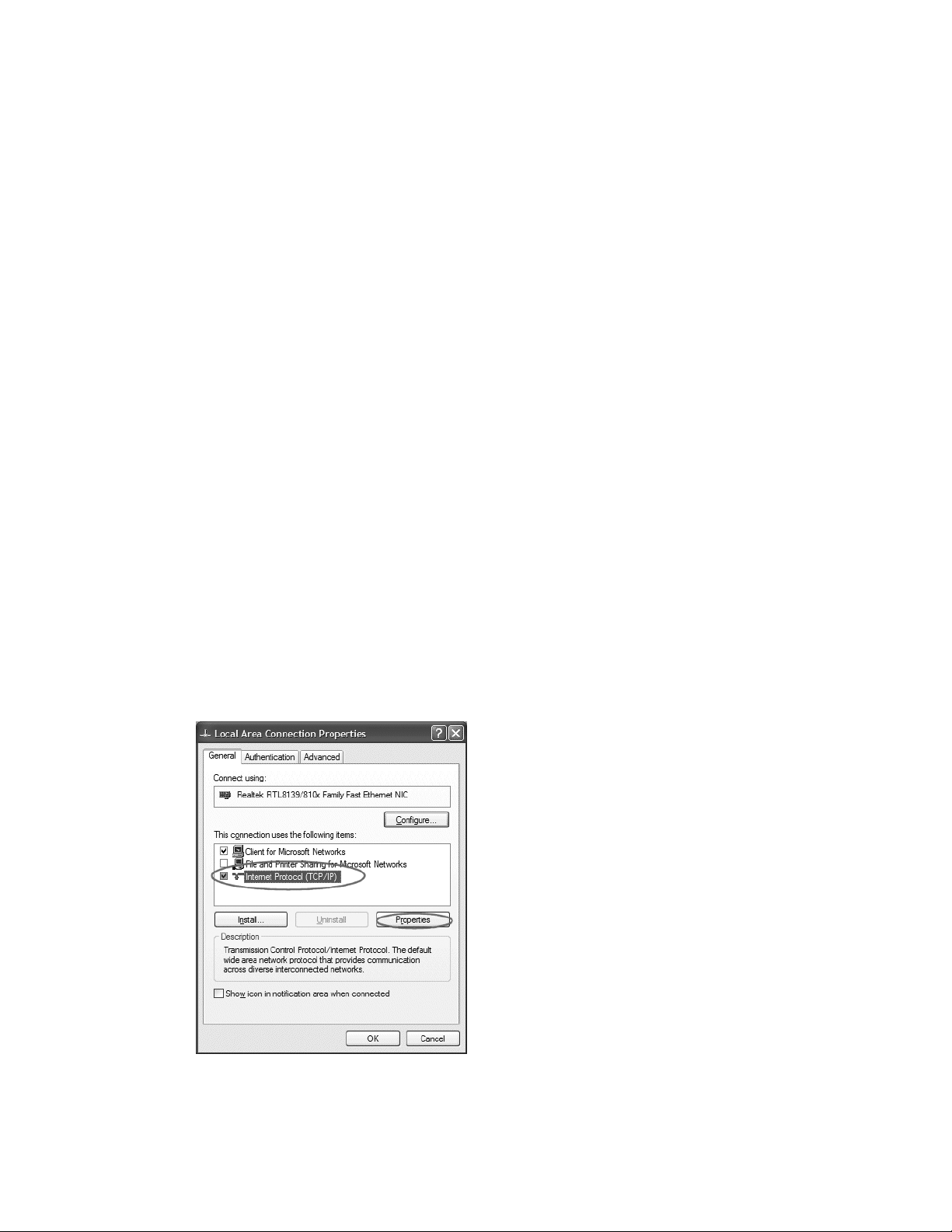
3. Give your computer a static IP address
For the duration of the configuration, your computer needs to have a specific IP address. Here’s how to change your
computer’s wired network adapter from automatic (DHCP) to fixed (static):
a. Windows XP
1. Open Windows Start menu.
2. Open Control Panel.
• Classic view: Open Network Connections
• Category view: Select Network and Internet Connections, and then Network Connections.
3. Double-click on your active LAN or Internet connection.
4. Click Properties. This opens the Local Area Connections Properties window. Proceed to 3c.
b. Windows 7
1. Open Windows Start menu. Type “network and sharing” into the Search box in the Start Menu and select
Network and Sharing Center when it comes up.
2. When the Network and Sharing Center opens, click on Change adapter settings.
3. If you have a wireless internet connection active, right-click on the icon and temporarily disable this
connection for best results.
4. Right-click on your active LAN or Internet connection and select Properties. This opens the Local Area
Connections Properties window.
c. Local Area Connections Properties (Windows)
1. In the General tab, highlight the Internet Protocol Version 4 (TCP/IPv4) or Internet Protocol
(TCP/IP) item, and click Properties.
This opens the Internet Protocol (TCP/IP) Properties window.
11
Page 15
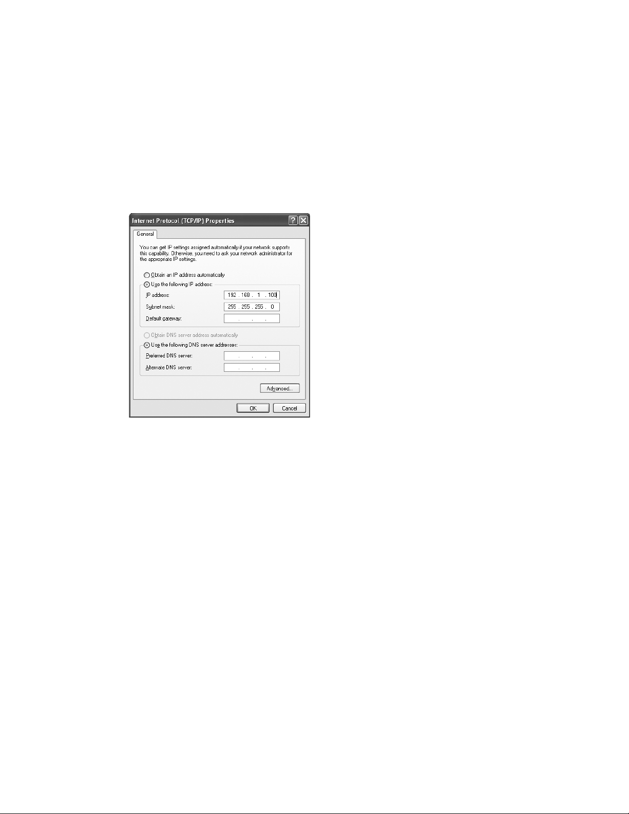
2. In the General tab, click Use the following IP address, and enter:
• IP address: 192.168.1.100
• Subnet mask: 255.255.255.0
• Default gateway: Leave blank
NOTE: We recommend 192.168.1.100 as the standard IP address; however, you may need to use a
different address if you are using a local switch already using this address
3. Leave the Use the following DNS server addresses fields blank
4. Click OK.
5. Click OK to close each window
d. Mac OS X
1. Click the Apple icon in the upper left hand corner of your screen.
2. Click the System Prefreneces.. option
3. In the Internet & Network section click the Network icon.
4. Select the network connection you use to connect to the internet — the one that has a green dot
in front of it. The green dot means the connection is active.
5. Click the Configure button which is close to the bottom of the screen
6. Click the Configure IPv4 drop down box and select the Manually option.
7. Enter:
• IP address: 192.168.1.100
• Subnet mask: 255.255.255.0
• Router: Leave blank
NOTE: We recommend 192.168.1.100 as the standard IP address; however, you may need to use a
different address if you are using a local switch already using this address
8. Click Apply Now.
12
Page 16
4. Load the configuration
1. Open a web browser and type in 192.168.1.104 as the URL
2. The CB2000 configuration screen will appear
3. Select Save/Restore
4. Select Browse and locate your Base Configuration File for this CB2000
5. Check the box if you want the IP address contained in the loaded configuration file to overwrite the IP
address on your connected CB2000 unit (useful if you are restoring a file that you know has the correct
IP address for this unit). This will allow you to skip points 12 through 14 below.
6. Click Load. Note that if you checked the box in point 5 above, the address of the CB2000 may change
and you will no longer be connected to it. You’ll need to enter the new address in your browser before
continuing to point 7.
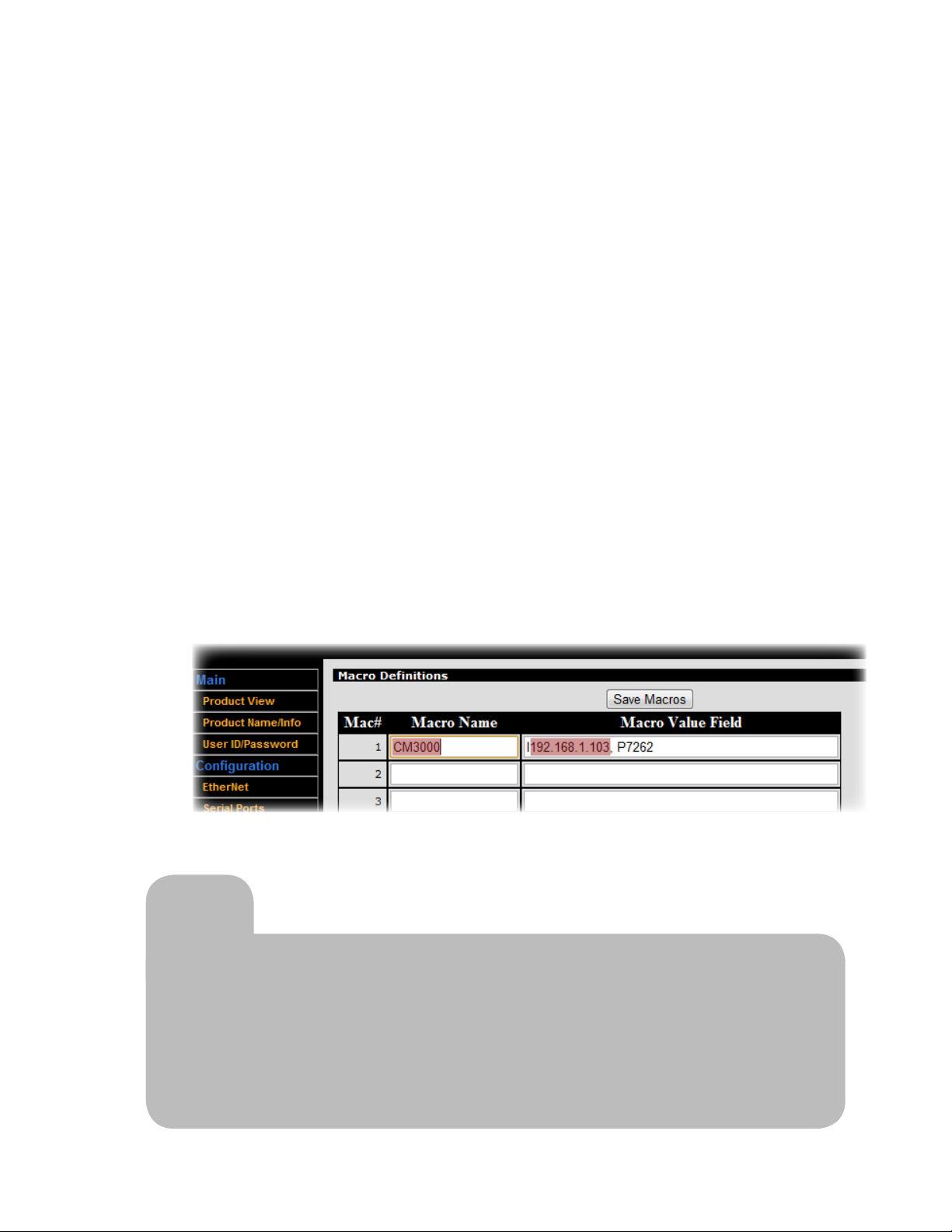
7. If you are sending commands over the network to a CM3000 amplifier/switch (as is common in an
ezRoom system), Soundpost, or other IP-addressable device, click Macro Definitions
• Your Base Configuration File contains variables that reference the IP addresses and ports of the
devices you’ll be sending commands to. Rather than repeating the addresses throughout the script
and having to update all of these as we configure each new room, we use a Macro Name variable
in the script that can be used in all rooms. You will simply change the definition of that variable for
each room installation.
• Your Base Configuration File will have at least one Macro Name defined, indicating the device to be
commanded from the CB2000.
• Replace the IP address portion of the Macro Value Field with the appropriate IP address for that
device in the room you’re working on. (Reference your Installer Planning Template; see Step 1)
• Click Save Macros
Tip
To save time on future configuration jobs, create a shortcut on your desktop
to 192.168.1.104 and name it CB2000 Configuration Screen.
If using the Apple Safari browser, do not use password protection during
reload. For best results, FrontRow recommends using the Google Chrome
browser.
13
Page 17
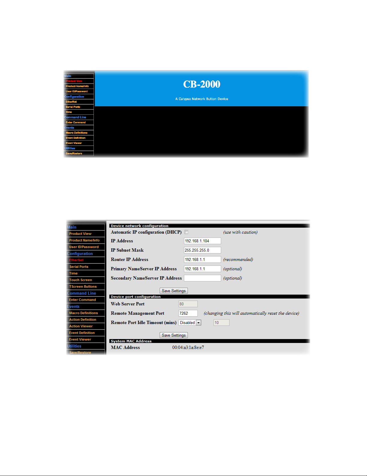
8. Select Time from the left-hand menu
9. Click Load Computer Time
10. Click Save Settings
11. Now define the IP address of this CB2000. Select Ethernet from the left-hand menu
12. Change the IP address, subnet mask, and router IP address to the appropriate values for this CB2000
(Reference your Installer Planning Template; see Step 1)
13. Click Save Settings (your browser will likely timeout; this is normal)
14. Disconnect the CB2000 from the Cat 5 cable, replace it in its anti-static bag, and apply a label with the
room number written on it so you are sure to install it in the right place on the job site.
15. Connect your next CB2000 and repeat Step 3.4 ‘Load the Configuration’ until all of your units are
programmed. Note that on some Windows
®
computers, you may need to clear the ARP cache in order
to communicate with the next device. See Appendix F.
14
Page 18

Step 5:
Nearly everything you need to install your FrontRow CB2000s is included in the boxes we shipped.
You will need some basic tools and materials, depending on how your classroom is built:
Physical Installation Prep
1. Materials you will need
• For each CB2000: US-standard single-gang (or, if using the CB50 volume control, double-gang)
AV box, electrical box, surface box, or mud ring
• Plastic raceway with screws (if not routing cable inside wall)
• Plastic cable (zip) ties
• Cable tacks/staples
2. Recommended tools
• Drill (or hammer drill for concrete walls)
• Drill bits (or masonry bits for concrete walls)
• Slotted screwdriver
• Level or ruler/tape measure
• Crimp pliers or scissors
• Tin snips (optional)
• Ladder
• Staple gun
• Safety goggles
General safety precautions
• Do not install or use the CB2000 near water or heat sources
• Clean only with a dry cloth
• Protect all cables from wear and damage from doors and other hazards
• Use only accessories specified by FrontRow
• Refer servicing to qualified service personnel
• Wear safety goggles when using power tools
15
Page 19
Step 6:
Estimated time for this step: 5-10 minutes
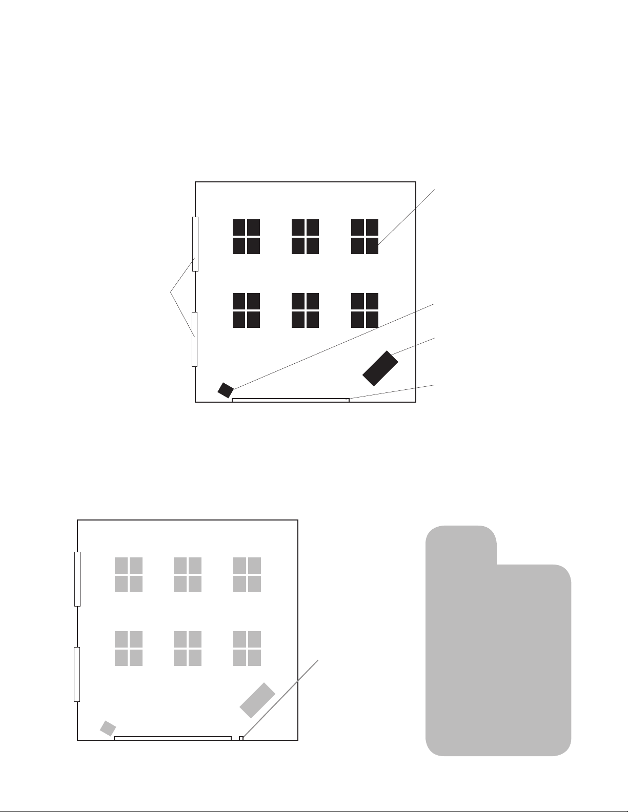
Now it’s time to decide where you’ll place the CB2000 (note that if your installation is part of an ezRoom,
be sure to refer to the Installer guides for the various ezRoom components for best results). To help you
decide, we’ll use the following layout of a typical classroom as an example:
Windows
Plan your installation
Student desks
TV / VCR / DVD
Teacher’s desk and
computer
White board
Top view of an example classroom
Decide where to put the CB2000
We recommend locating the CB2000 where the instructor is likely to spend most of her or his time. In the example
below, we’ve placed the CB2000 conveniently near both the whiteboard and the teacher’s desk.
Tip
If using the TB14
to control devices
via IR signaling,
remember that
You’ll install the CB2000
at teacher eye-level
where he or she is likely
to spend a lot of time.
a cable length
of 15m/40ft is
allowed — so
select your
CB2000 position
accordingly.
A good place for the CB2000
16
Page 20

Step 7:
Install your CB2000
Estimated time for this step: 15 minutes
With the positions and programming of all your major components settled, you can now install your CB2000s. Refer to
the diagrams in Step 1 as you connect components.
1. Install a double-gang electrical box (if using CB2050 or CB2000 with CB50) or single-gang electrical box (for
CB2000), surface box, or mud ring according to the manufacturer’s instructions.
2. If using the CB2000 with a FrontRow CM3000 amplifier/switch (if not, skip to #3):
• Install Cat 5 cable from the electrical box to the location of the FrontRow CM3000. Ensure the cable is installed in
compliance with your national and local electrical codes.
• Connect the Cat 5 cable to the CB2000’s Network jack.
WARNING: TO AVOID DAMAGE, CONNECT TO THE CB2000’S “NETWORK ONLY“ JACK!
If you are controlling a serial device (e.g., projector), connect the provided serial cable(s) to the CM3000’s
COM1 captive screw connector. Wiring is as follows:
• Black (ground) to GND
• Red (input to device) to TX1
• White (output from device) to RX1
IMPORTANT: Be sure to keep wiring and Action commands consistent to avoid
problems. For example, serial Actions sent to COM1 should use the TX1/RX1 pins.
(See Appendix A).
• If you are controlling a device via infrared (e.g., a DVD player), connect an IR emitter cable (not included; part
number 520-3001-001) to the TB5 IR Emitter Cable Extension Adapter (not included; part number 310-2546-120)
and connect the TB5 to the CM3000’s IR captive screw connector. Secure the emitter end to the controlled
device’s infrared sensor. Be sure the CB2000 jumper (see page 2) is connecting pins 2 and 3.
• If you are using general purpose input (GPI) signals, be sure the CB2000 jumper (see page 2) is connecting
pins 1 and 2.
• Connect the Cat 5 cable to one of the CLAN jacks on your CM3000.
• If connecting your ezRoom to a local area network (for example when used with a Conductor system), connect
the network cable to LAN1 or LAN2 on the CM3000.
3. If using the CB2000 as a
• Mount the TB adapter(s) securely near the projector or other device to be controlled.
• Thread Cat 5 cable from the electrical box to the location of the TB adapter(s). Ensure the cable is installed in
compliance with your national and local electrical codes.
• Connect the Cat 5 cable to the CB2000’s AUX jack.
standalone controller
with the TB12 adapter, or TB6 and TB8 adapters:
WARNING: TO AVOID DAMAGE, CONNECT TO THE CB2000’S “AUX“ JACK!
17
Page 21
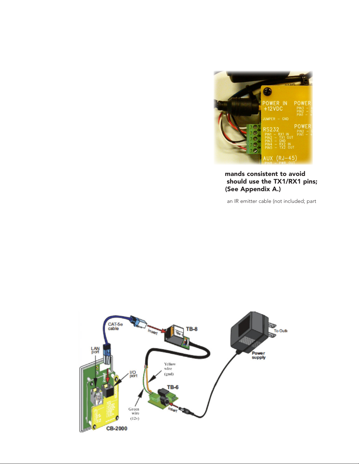
4. If your configuration includes the TB14:
• If you are controlling a serial device (e.g., projector), connect the provided serial cable(s) to the TB14 adapter’s
RS232 captive screw connector. You can have up to two separate serial cables. Wiring is as follows:
• To control the first device:
• Black (ground) to Pin 3/GND
• Red (input to device) to Pin 2/TX1 OUT
• White (output from device) to Pin 1/RX1 IN
• To control a second device:
• Black (ground) to Pin 3/GND
• Red (input to device) to Pin 5/TX2 OUT
• White (output from device) to Pin 4/RX2 IN
IMPORTANT: Be sure to keep wiring and Action commands consistent to avoid
problems. For example, serial Actions sent to COM1 should use the TX1/RX1 pins;
actions sent to COM2 should use the TX2/RX2 pins. (See Appendix A.)
• If you are controlling a device via infrared (e.g., a DVD player), connect an IR emitter cable (not included; part
number 520-3001-001) to the TB14’s IR jack and secure the emitter end to the controlled device’s infrared sensor.
You can control up to two separate infrared devices. Be sure the CB2000 jumper (see page 2)
is set correctly.
• If you are using general purpose input (GPI) signals, be sure the CB2000 jumper (see page 2) is set correctly.
• Connect the power supply to the TB14 adapter
• Connect the Cat 5 cable to the AUX jack on the TB14 adapter
• If connecting your ezRoom to a local area network, connect the network cable to the “Network Only” jack
on the CB2000.
If your configuration includes the TB8 + TB6:
• Connect the CB2000 to the TB8 and TB6 as shown below.
18
Page 22
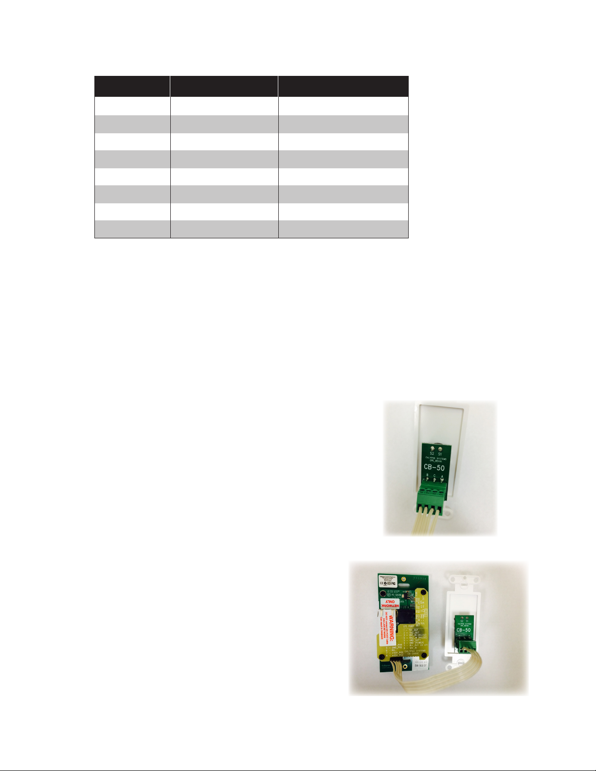
TB8 wires: Use the below table as a reference for wiring your to your system:
Pin # Wire Color Function
1 Orange TX1
2 Brown TX2
3 Red RX1
4 White RX2
5 Black GND 1 (IR or GPI)
6 Yellow GND 2 (Power)
7 Blue IR Out+ or GPI
8 Green 12V or 9V
If controlling a device using IR, connect the Blue and Black wires from the TB8 to the TB6, then your 3.5mm IR
cable to the TB6 IR connector. Make sure to set the jumper on the CB2000 correctly for IR.
If using the CB2000 to control a device in response to a GPI signal, use the Blue and Black wires for GPI and set
the jumper on the CB2000 correctly.
Using the RS232 adapter cable provided with your system, connect the Red wire on the cable (input to projector)
to the Orange wire on the TB8 (TX1). Connect the White wire on the cable (output from projector) to the Red
wire on the TB8 (RX1). Connect the Black wire on the cable (GND) to the Black wire on the TB8 (GND).
If using a second RS232 device use the TX2 and RX2 wires (Brown and White) plus ground (Black) on the TB8 to
connect to it.
5. If using the CB50 volume control:
• If the 4-pin ribbon cable was not already attached to
the green captive screw connector, insert it groove
side up and secure it.
• Connect the other end of the 4-pin connector cable
into the black clip on the CB2000 (see page 2)
6. Confirm that button presses result in the expected
actions. If there are any errors, check wiring and confirm configuration control logic. (Refer to Step 3 and
Appendix A as needed.)
7. Screw the CB2000 panel, (and CB50, if any) into the
electrical box with the screws provided (see diagram at
right).
8. Check for good responsiveness of buttons to touch;
if needed, recalibrate using the built-in calibration tool
(see Step 1.2)
19
Page 23
Appendix A:
You can use the CB2000 to its full potential by learning to program your own configuration files. Each CB2000 includes a
utility for creating, modifying, loading, and/or saving the configuration file. We strongly recommend that you use the
following workflow for any custom programming:
1. Create Macros (covered in Appendix A.2) — Variables that refer to specific IP-addressable devices
2. Create Events (covered in Appendix A.4) — The kinds of situations in which you want to initiate one or more Actions
3. Create Actions (covered in Appendix A.3) — Specific control commands for specific devices
4. Set Preferences (covered in Appendix C) — Set other parameters (e.g., timeout, security)
You can certainly deviate from this workflow, but you will probably waste some time flipping back and forth between
programming screens unnecessarily.
Control Logic Programming
1. Connect to the CB2000 through A Web Browser
On a computer connected to the LAN, type in the IP address of your CB2000 — the default is 192.168.1.104 If you
have not already reassigned it (see Step 3 for guidance).
2. Define Macros
Defining Macros makes mass deployment of CB2000s easier by letting you define Actions using variables to
represent the IP addresses of the devices you’ll control. This means that your configuration file can be written as
a template, with IP addresses explicitly defined in only one place (the Macro Definitions) rather than repeated
throughout your Actions. This saves a tremendous amount of labor as you re-use the configuration file to control
new devices from room to room.
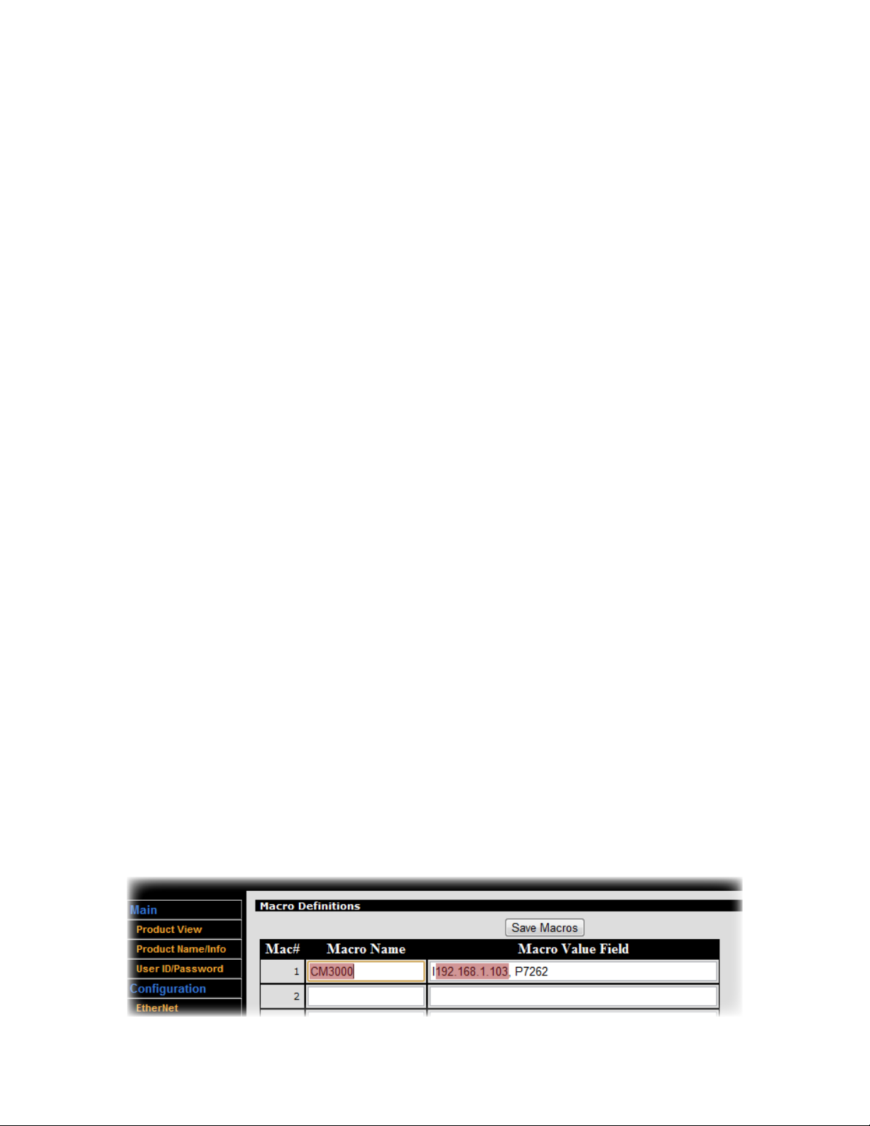
• Choose Macro Definitions
• Enter up to 16 macro names and values in the following format:
• Macro Name: Any name can be used, but it is most useful if this is an easily recognizable, generic, and concise name for a device type used throughout your installation (e.g., CM3000, Projector, etc.)
• Macro Value Field: The value of this variable for this particular installation. For NET commands (see
Appendix A.3) this takes the format:
Iipaddress,Pport (e.g., I192.168.1.201,P7262)
For HTP commands (see Appendix A.3) this simply takes the format:
ipaddress (e.g., 192.168.1.201)
• Click Save Macros.
The Macro definitions are included as part of the saved configuration file. When you use this configuration file as a
template in similar installations, simply change the value of each defined Macro to the appropriate IP address. For
example, in subsequent rooms, we may set the value of ‘CM3000’ to I192.168.1.202,P7262; I192.168.1.203,P7262;
and so on.
20
Page 24
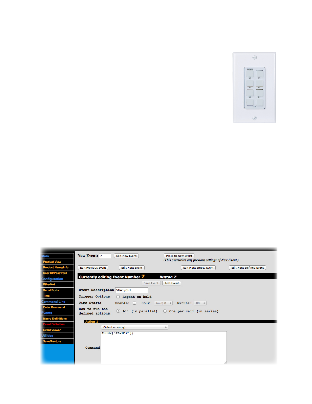
3. Define Events
With your collection of discrete Actions defined, you can now specify what Events will cause one or more of those
Actions to be executed.
In most cases, a user pressing a button on the touch screen is what tells the CB2000
that an Event has occurred. However, you are also free to specify any general purpose
input or NOP signal you wish as a Trigger. Alternatively, you can schedule an Event.
Events 1–8 are reserved for the 8 buttons on the CB2000:
To create or edit an Event:
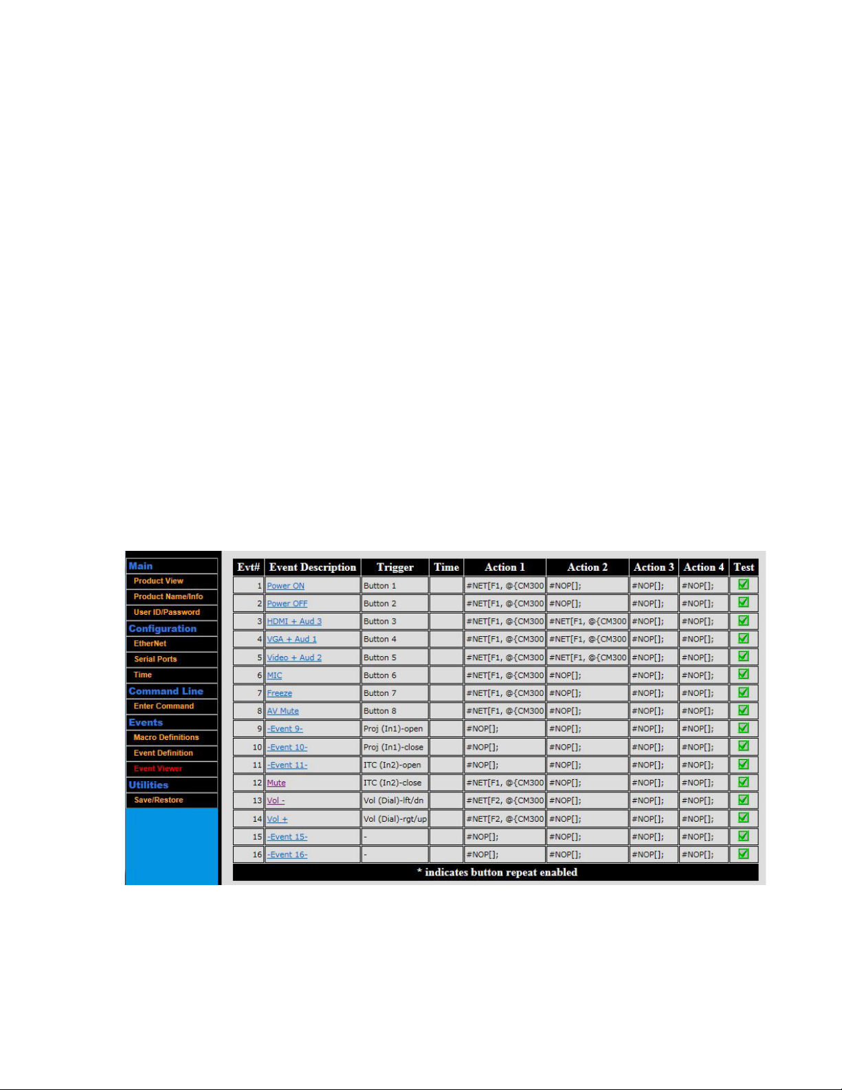
• Select Event Definitions. (Note that it may be more convenient to navigate to previously defined Events via the
Event Viewer.)
• You can move through various Events using the buttons at the top of this screen. (CAUTION: Save your work
on the current Event before navigating away or your changes will be lost!)
• Edit New Event: Lets you modify the Event definitions for a saved Action.
2
1
3
4
6
5
8
7
• Paste to New Event: Useful for cloning the current Event (displayed in the black strip labeled “Currently editing Event Number xx.”) to another Event. Change the New Event field to the number of the target Event and
click the Paste to New Event button. The current Event data will be copied to the target Event. (CAUTION:
This will overwrite the target Event!)
• Edit Previous Event: Moves to the previous Event record
• Edit Next Event: Moves to the next Event record.
• Edit Next Empty Event: Moves to a new undefined Event record.
• Edit Next Defined Event: Moves to the next defined Event (skipping over any undefined records)
21
Page 25
• Give the Event a useful description (e.g., “Mute”)
• If you want to have the Event initiated by a button press, be sure the event number corresponds to the correct
button (see Appendix B.2).
• If you want to have the Event initiated by a general purpose input signal, select Event 9 or higher (and be sure
the CB2000 jumper (see page 2) connects pins 1 and 2). The CB2000 constantly scans all inputs, searching for an
event that matches any Triggers you have defined. When a matching event is recognized, the corresponding output actions are executed in rapid succession.
• If you want to have the Event initiated according to a schedule, select the schedule you’d like using the Time
Start menu
• Select the mode in which you would like to run the defined Actions:
• All: the CB2000 will attempt to execute all Actions for that event simultaneously, but in no particular order
(e.g., Action 2 and Action 1 and Action 3...)
• One per call: the CB2000 will treat the actions as a loop, executing the next Action in the series each time the
Event is initiated (e.g., Action 1 on the first button press, Action 2 on the second button press, Action 1 on the
third button press, etc.). This is useful for toggle functions like power, or freeze.
• Assign or remove one or more Actions to this Event using the fields under Actions 1–4 and the guidance under
Create Action (Appendix A.10).
If the CB2000 has been physically installed, you can test the Event you created by clicking the Test Event button.
(Note that you can also test Events via the Event Viewer by clicking on the checkmark to the right of each Event.)
Be sure to Save the Event before moving to another section.
Events 1-8 are used for the CB2000 buttons.
Events 9-10 are for use with the GPI.
Events 12-14 are used with the CB50.
22
Page 26
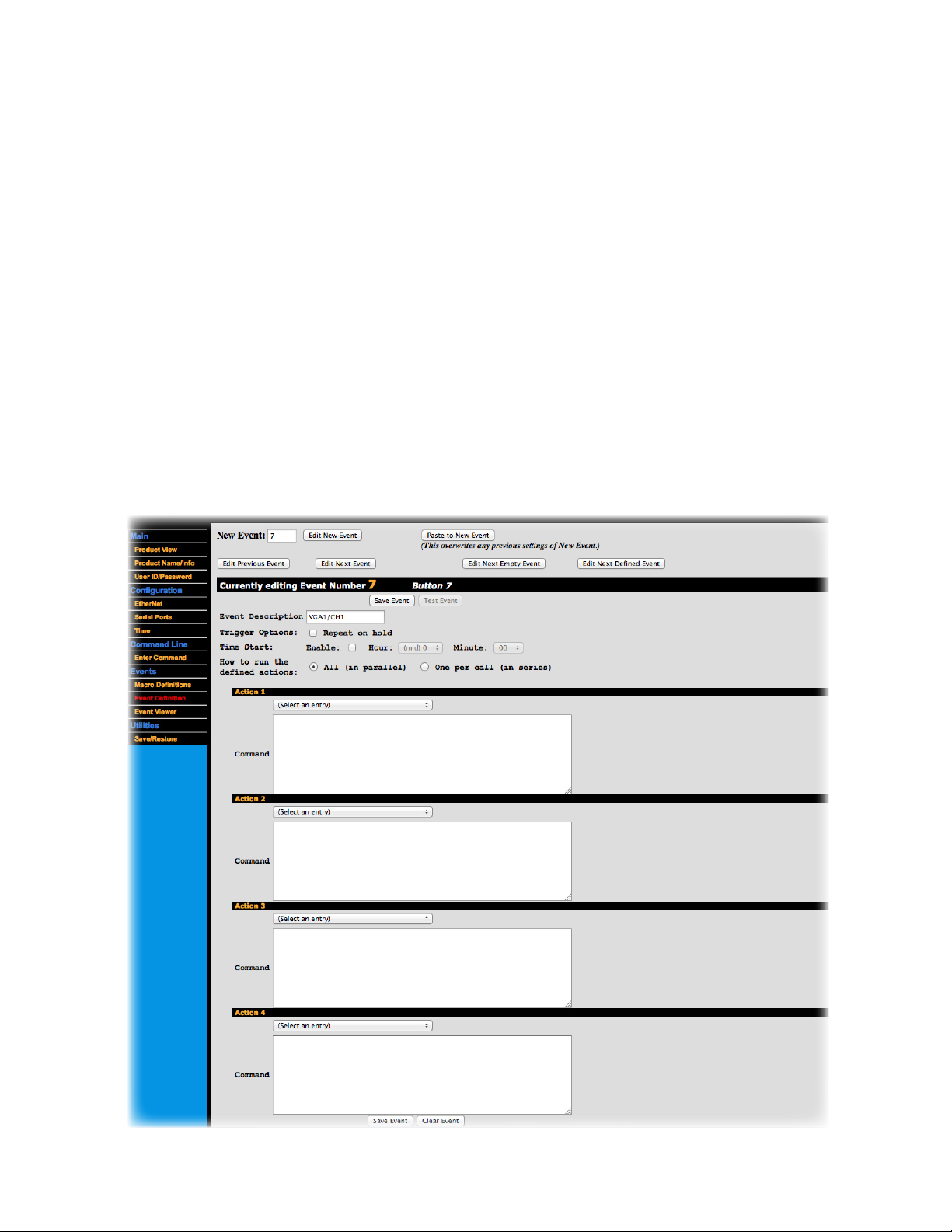
4. Create Actions
Actions are specific instructions associated with events that are sent to specific devices.
To create or edit an Action:
• Move to the event you want to work on.
• Define the Action using the fields under actions 1–4.
• Select a template for the Action from the drop-down list:
• NET Command — For commands to be sent to IP-addressable devices over your network
• HTP Command — To initiate an intercom call via a FrontRow Conductor™ server to a FrontRow CM3000
elsewhere on the network (e.g., the office or another classroom). For schools using the Conductor™ IP
paging and bell system only.
• Serial Transmit — For commands to be sent directly to serial devices using RS232 protocol.
• IR-Out Universal Command — For commands to be sent directly to devices that can only be controlled via
infrared remote.
• Alarm Command — For use with FrontRow CM3000 only. Initiates a beep with a short delay.
• NOP Command — Effectively deletes an Action that was previously defined.
• Use the syntax template that appears to build the specific Action you want.
23
Page 27

Network (NET) Commands*
Syntax: #NET[Connection, StringType, Device, ‘Command’];
Name Required/Optional Data Type Format Description
Connection Required Variant Fn
Defines the connection type:
• TCP/IP (1)
where n is 1 or 2
StringType Optional Variant Tn
• UDP (2)
Defines the string type:
• ASCII string (1)
where n is 1 or 2
• Hexadecimal (2)
If you leave StringType blank, a
default of T1 is assumed.
Device Required Variant If using Macros (recommended):
A string expression that’s the valid
name of a Macro (see Appendix
@{MacroName}
A.2) or the IP address and port of
device to be controlled.
For explicit device references:
IAddress, PPort
Default port for CB2000 is 7267
Command Required Variant Specific to device. For CM3000
commands, see Appendix D;
A string expression that contains
the command.
for other device commands see
manufacturer’s instructions.
Example (increments the audio input channel of a CM3000 by one over TCP/IP protocol using an ASCII string):
#NET[F1, @{CM3000}, ‘#AUD1[I+];’];
Intercom (HTP) Commands*
Syntax: #HTP[http://Server/calypso/conductor/?/call/Device];
Name Required/Optional Data Type Format Description
Server Required Variant If using Macros (recommended):
A string expression that’s the valid
name of a Macro (see Appendix
@{MacroName}
A.2) or the IP address of the Con-
ductor™ server.
For explicit device references:
IP address of the Conductor
server
Device Required Variant If using Macros (recommended):
A string expression that’s the valid
name of a Macro (see Appendix
@{MacroName}
A.2) or the IP address of a CM3000
located on the network
For explicit device references:
IP address of the CM3000
Example (initiates a proxy intercom request from the CM3000 located in the office):
#HTP[http://@{DRS5000}/calypso/conductor/?/call/@{OfficeCM3000}];
24
Page 28
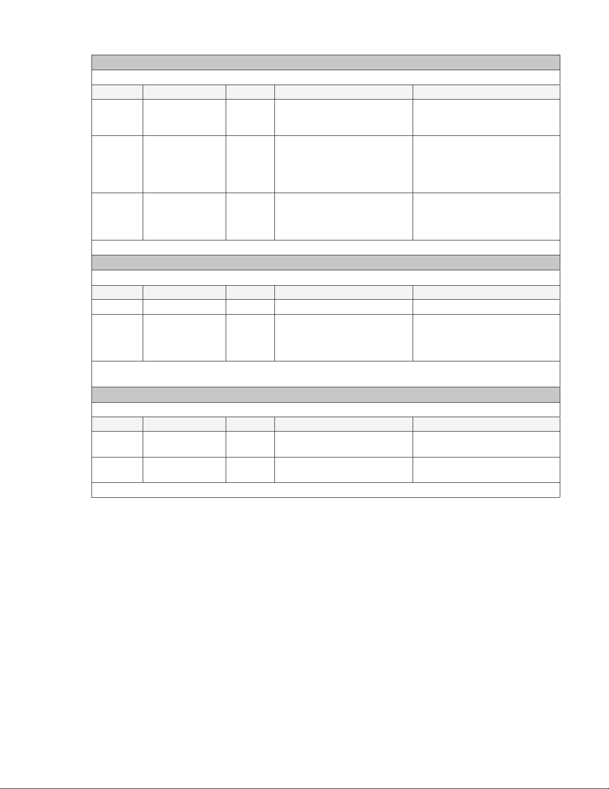
Serial (COM) Commands*
Syntax: #COMn[StringType,”Command”];
Name Required/Optional Data Type Format Description
n Required Variant Use 1 for COM1; use 2 for
COM2.
Denotes the COM port to be
used, corresponding to the serial
device to be controlled.
StringType Optional Variant Tn
Defines the string type:
• ASCII string (1)
where n is 1 or 2
• Hexadecimal (2)
If you leave StringType blank, a
default of T1 is assumed.
Command Required Variant Specific to device. For CA1000
commands, see Appendix E;
A string expression that contains
the command.
for other device commands see
manufacturer’s instructions.
Example (turns on a projector via COM 1 using an ASCII string command): #COM1[T1,”PWR ON\r”];
IR-Out Universal Commands*
Syntax: #XROn[F2,”Command”];
Name Required/Optional Data Type Format Description
n Required Variant Use 1 for IR port 1. Denotes the IR port to be used.
Command Required Variant Specific to device. See the IR
Learning section under Appen-
A string expression that contains
the command.
dix A.5 or see manufacturer’s
instructions.
Example (turns on a DVD player):
#XRO1[F2,” 40000300015430309DA03F508FC03A704D6039...3A704D803F808FC03A704D403A104FB03A704D903”];
Alarm Commands*
Syntax: #ALM[“Command”,DTime];
Name Required/Optional Data Type Format Description
Command Required Variant
Use ON to start the alarm. Use
Starts/stops the beep.
OFF to stop the alarm.
Time Required Variant Integer representing multiples of
Sets the duration
4ms duration.
Example (turns on the beep with a 200ms duration): #ALM[“ON”,D50];
*For complete programming guidance, refer to the Calypso Action Control Language (CACL) manual under the
Resources tab of the ezRoom web page: www.gofrontrow.com/products/frontrow-ezroom
• If the CB2000 has been physically installed, you can test the action you created by clicking the Test Action
button. Note that you can also test Actions via the Action Viewer by clicking on the checkmark to the right of
each Action. Alternatively, the Enter Command screen can be a useful tool for testing and troubleshooting
Actions (see Appendix A.6).
25
Page 29

5. IR Learning
If you are controlling devices that lack serial control ports (the recommended method for controlling non-networked
devices) but have an infrared remote control, you can place your CB2000 into an IR learning mode.
• Choose Enter Command
• Select one of the ‘Learn Universal IR...’ options from the drop-down list
• Click Send CMD
• Hold the device’s IR remote control within 15cm/6in of the CB2000 button panel, then press the button on the
remote control for the function to be learned
• The IR command string will appear in the Receive Command window, and is available for copying and pasting
into an Action Definition (see Appendix A.3).
When an IR command is learned the controller inserts an “IR Header” onto the front of the command. Each Hex
byte of this header contains information pertaining to certain IR parameters of a learned code. It is not retransmitted with the IR code. It tells the controller what to do with the code string that follows. It is helpful to understand the
first 6 bytes of this header when dealing with difficult IR devices.
Example IR header: 40 00 03 00 01 54
BYTE 1:
BYTE 2:
BYTE 3:
BYTE 4:
BYTE 5:
BYTE 6:
Carrier frequency of the IR command: 28kHz, 30kHz, 32kHz, 36kHz, 38kHz, 40kHz and 56kHz. This byte
should not be changed unless there is a need to strip the carrier from the IR signal. This can be accomplished by changing the byte to 00.
Idle/Delay time – a user adjustable time to override the existing idle gap between IR bursts when the IR
command is sent more than once, or to add a delay time after the last IR command burst. Allowable timing
increments are 04h – 7Fh for an idle gap override, and 80h - FFh for an added delay time. Each hex unit is
equal to 10ms delay. For example, a value of 0Ah (decimal 10) would insert a delay of 100ms between the
IR bursts. Default is 00h, which means that the controller will use the idle time that is part of the learned IR
code. A value of 90h (decimal 144) would add a 1.44 second delay after the last IR command sent.
Repeat - selects how many times the IR command is to be repeated. Allowable values are from 01h to FFh
(must be in Hex form!). Default is 03h and 00h is invalid.
Repeat Mode - three selections: 00h = repeat the entire IR command, 01 = repeat the IR header only once,
02h = repeat the IR command with an offset. Default is 00h.
Offset – displays which section of the IR burst was learned.
01 = Learn Universal code
02 = Learn Universal code w/1 skip
03 = Learn Universal code w/2 skips
Data Length – displays the size of the data string in Hex form including the header.
26
Page 30
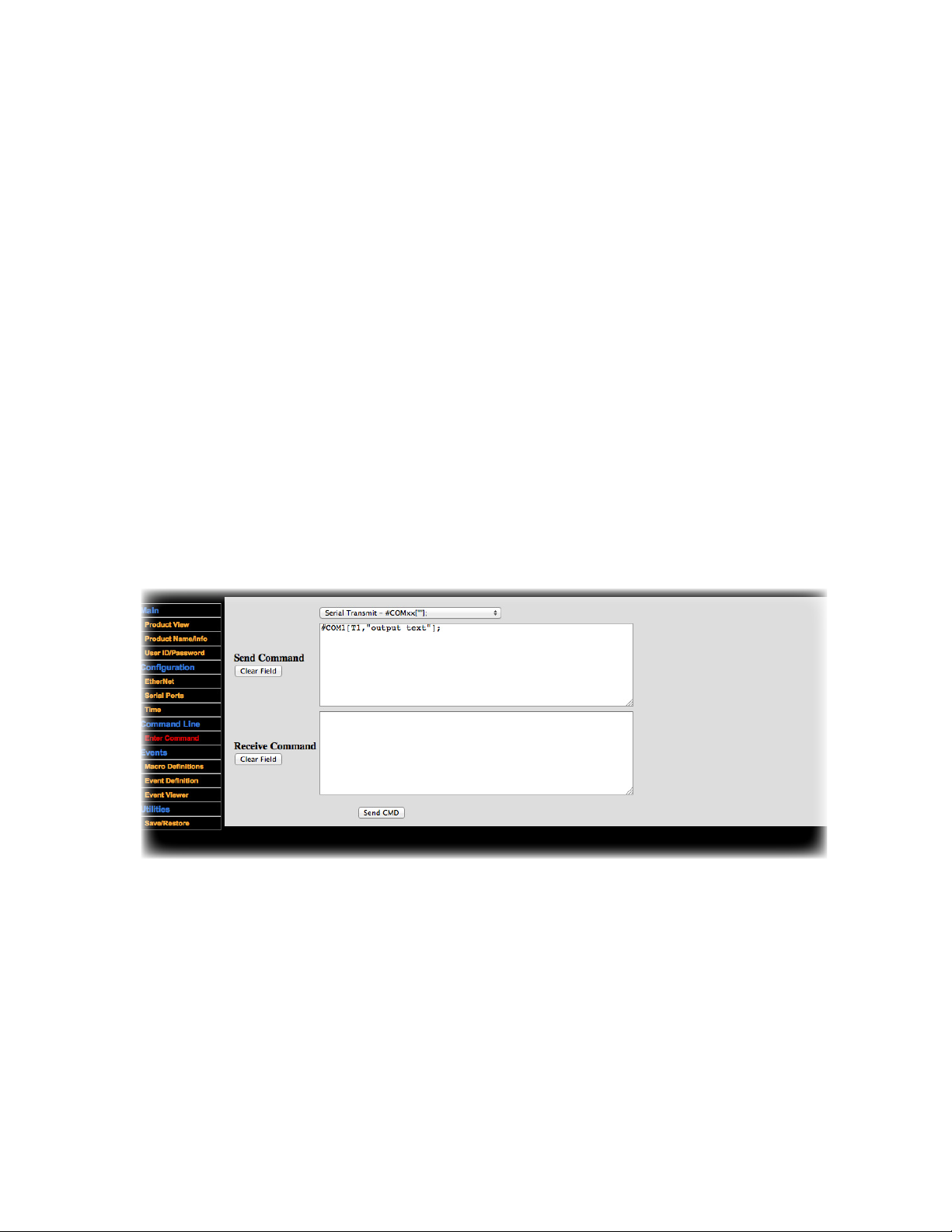
6. Enter Command
The Enter Command interface lets you test proper connection and function by entering and executing command strings.
You can use this to verify the correctness of a command before you enter it into an Action. For serial commands, it can
also be used to see any data returned from the remote device.
• Choose Enter Command
• Select a test command from the drop-down menu (the test command will appear in the Send Command window):
• For Serial:
• Serial Transmit - #COMxx[“”] TX
• Serial Receive - #COMxx[] RX
• For Infrared:
• IR- Out Universal Command- #XROxx[F2] output
• Learn Universal IR code - #XRI1 [F2] input (universal header uses fixed 40K, user can modify)
• For TCP:
• NET Command (TCP) - #NET[F1,...]
• For test command:
• Alarm Command #ALM[”ON”]
• Click Send CMD
• The Receive Command field is populated when it receives a response back from a connected serial device
27
Page 31
Appendix B:
You can use the CB2000 to its full potential by learning to program your own configuration files. Each CB2000 includes a
utility for creating, modifying, loading, and/or saving the configuration file. We strongly recommend that you use the
following workflow for any custom programming:
1. Create Macros (covered in Appendix A.2) — Variables that refer to specific IP-addressable devices
2. Create Events (covered in Appendix A.4) — The kinds of situations in which you want to initiate one or more Actions
3. Create Actions (covered in Appendix A.3) — Specific control commands for specific devices
4. Set Preferences (covered in Appendix C) — Set other parameters (e.g., timeout, security)
You can certainly deviate from this workflow, but you will probably waste some time flipping back and forth between
programming screens unnecessarily.
Setting Preferences
1. Connect to the CB2000 through A Web Browser
On a computer connected to the LAN, type in the IP address of your CB2000 — the default is 192.168.1.104 If you
have not already reassigned it (see Step 3 for guidance).
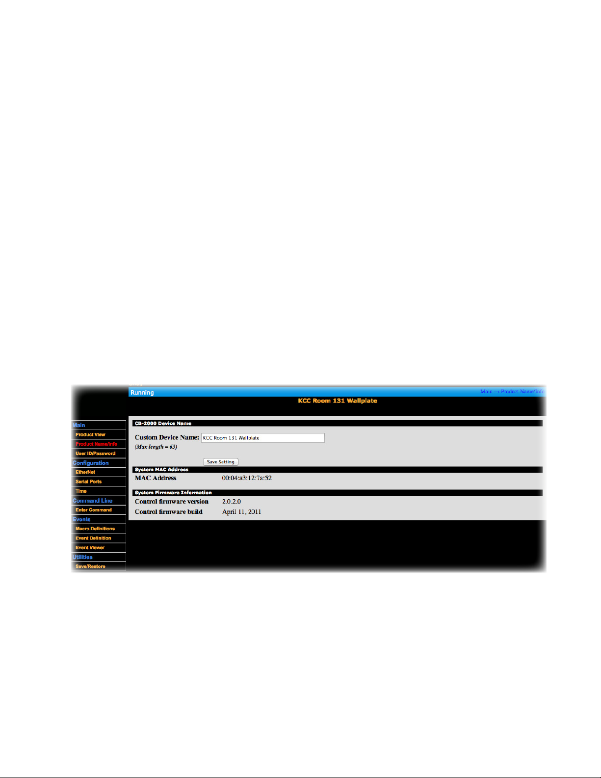
2. Name Your CB2000
• Choose Product Name/Info > Custom Device Name
• Enter a recognizable name for easier identification on the network
• Click Save Setting
28
Page 32
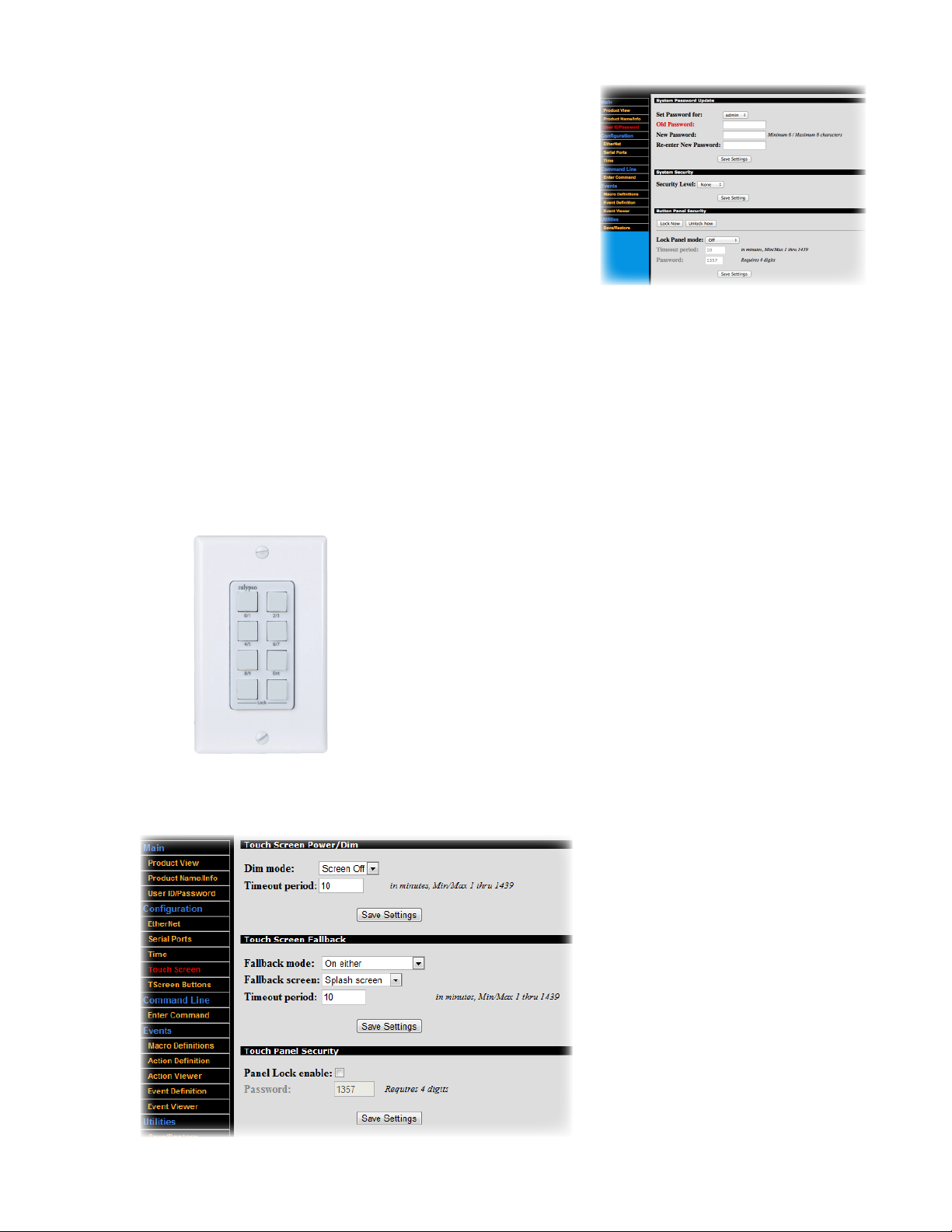
3. Web Access Password
To set a password to deter configuration changes by network hacks:
• Choose User ID/Password
• Type in the old password (the default is ‘calypso’)
• Enter/re-enter the new password
• Click Save Settings in the top section
• Select Admin from the Security Level drop-down
• Click Save Settings in the middle section
Select the conditions upon which the CB2000 panel will lock under Lock Panel Mode:
• Off (i.e. the panel will never lock)
• Timeout (the panel will lock after a defined period of inactivity)
• Pad-Press Press (the panel will only lock if the user presses two buttons simultaneously)
• Both (the panel will lock either upon pressing two buttons simultaneously or upon a defined period of inactivity)
• Enter the delay in minutes between the last button press and locking under Timeout Period
• Set a Password for unlocking the panel (the default is 1357; must be a 4- digit odd number). The user types the
password or the keypad of the CB2000 to unlock it, with the digits corresponding to the following button positions:
2
1
3
4
6
5
8
7
• Click Save Settings in the bottom section
You can also use the Lock/Unlock Now buttons to test the behavior or initiate modes remotely.
29
Page 33
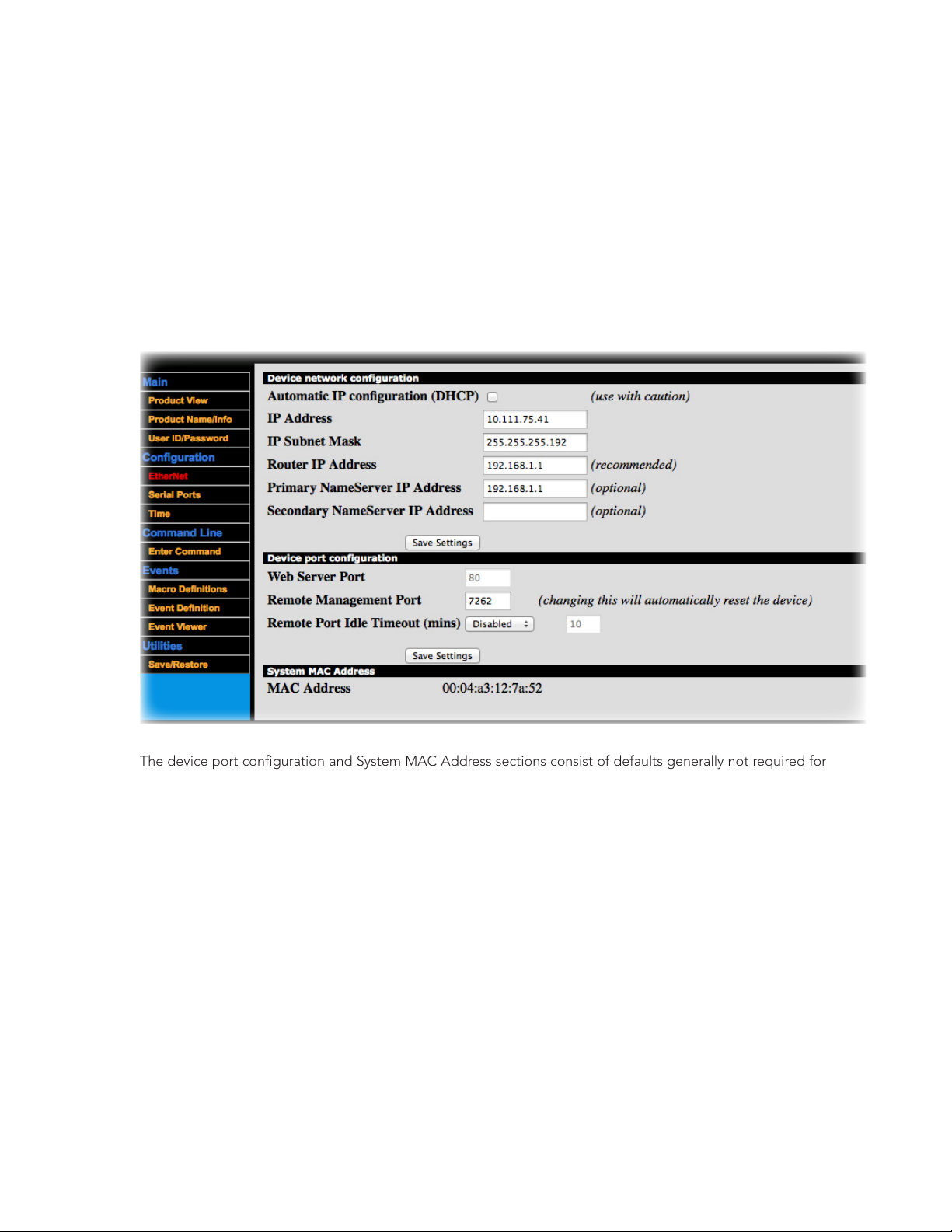
4. Advanced Ethernet Settings
• Choose Ethernet. As needed, make the following communication settings adjustments:
• Automatic IP Configuration (DHCP): Use only if you are thoroughly familiar with DHCP configuration
• IP Address
• IP Subnet Mask (for your computer network grouping; default is 255.255.255.0)
• Router IP Address of your subnet
• Primary NameServer IP Address (default is 192.168.1.1)
• Secondary NameServer IP Address
• Click Save Settings in the top section
The device port configuration and System MAC Address sections consist of defaults generally not required for
modification. The Web Server Port (set at 80) is also static and is visible here for informational purposes only.
Next, the Remote Management Port is a Controller Network Action Protocol (CNAP) registered port set at
7262 for command- line (CNAP) functions only. It is used by external software to send commands to the controller.
The Remote Port Idle Timeout field’s default setting is Disabled. When active, it sets the duration (in minutes)
before the controller releases the remote communication port after a period of inactive controller communication.
If a special case arises where your system does require configuration, contact FrontRow Technical Services at
[email protected] for assistance.
30
Page 34
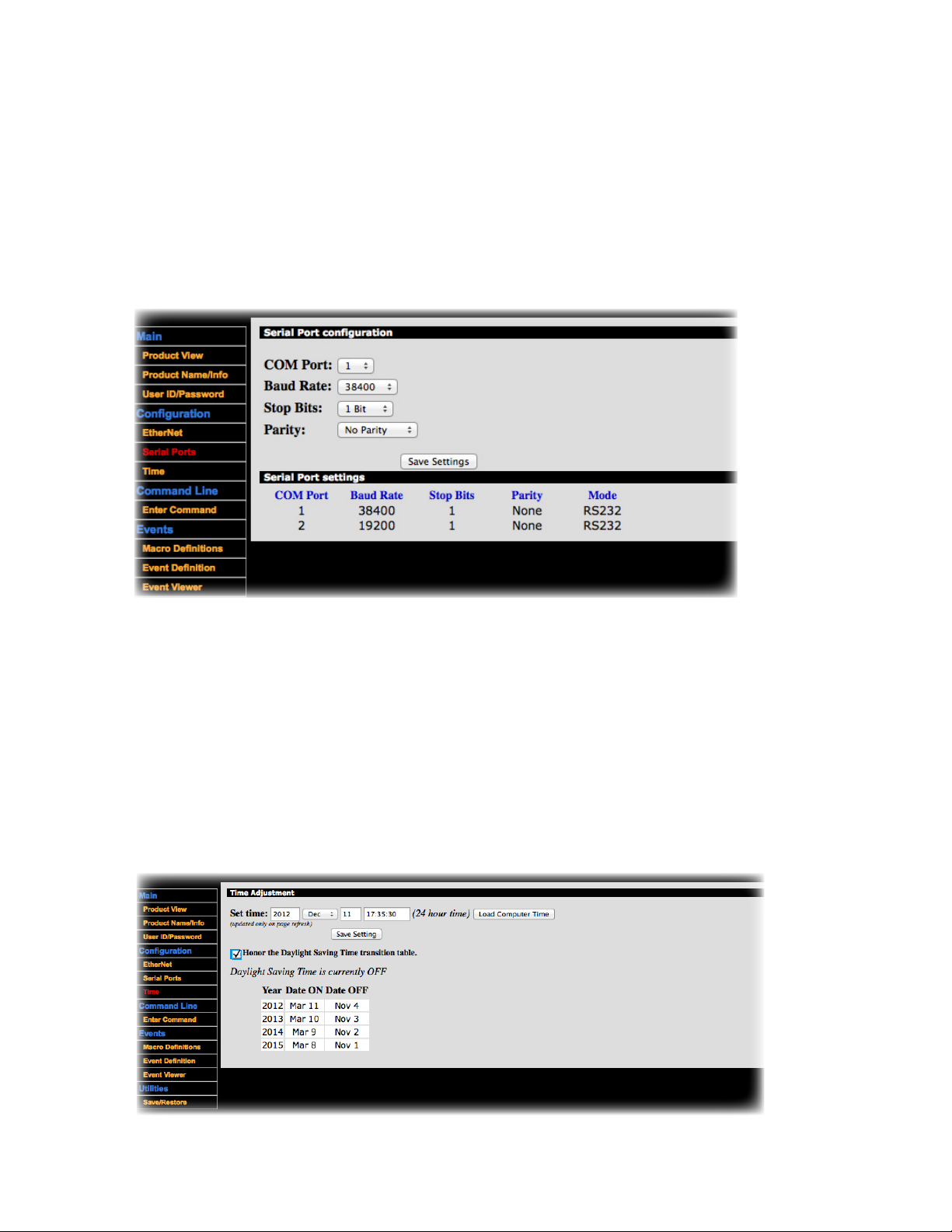
5. Advanced Serial Port Settings
• Choose Serial Ports. The current settings can be viewed at the bottom of this web page. As needed, make the
following port setting adjustments (e.g., as needed for controlling a specific projector):
• COM Port number (default is 1)
• Baud Rate (default is 19200)
• Stop Bits (default is 1 Bit)
• Parity (default is No Parity)
• Click Save Settings
6. Set the Time
• Choose Time
• Either type the data into the fields provided or press the Load Computer Time button to retrieve the computer’s
current time/date.
• To enable (or disable) the Day Light Saving (DST) mode, click the box to Honor the Daylight Saving Transition
Table
. A message below the check box indicates whether DST is currently OFF or ON. A three- column table at
the bottom of the view displays the current defined year and the next three years. No actual DST data can be
changed with this interface. Contact FrontRow Technical Service at [email protected] for DST modifications.
• Click Save Settings
31
Page 35
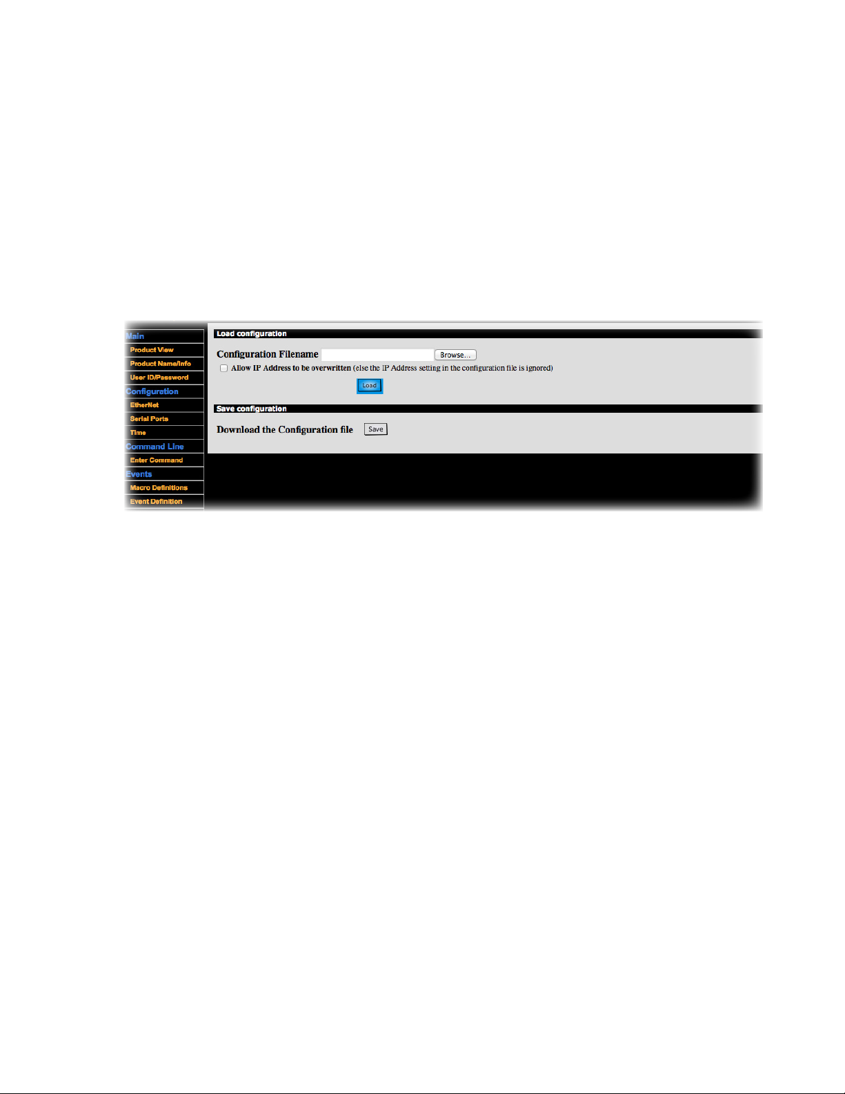
7. Save/Restore
Use this window to either load an existing configuration file onto your CB2000 or save the current configuration to a
file on your computer for re-use as a template for other CB2000 units
To load an existing configuration file onto your CB2000:
• Select Save/Restore
• Select Browse and locate your Base Configuration File for this CB2000
• Check the check box if you want the IP address contained in the loaded configuration file to overwrite the IP
address on your connected CB2000 unit.
• Click Load
Note that other operations such as IP address definition are often required. See Step 4.
To save your current configuration file to use as a template for other CB2000s:
• Select Save/Restore
• Click Save
• To save your configuration file to a specific folder, right-click on the Save button and choose Save Target As... or
Save Link As... depending on your browser
32
Page 36
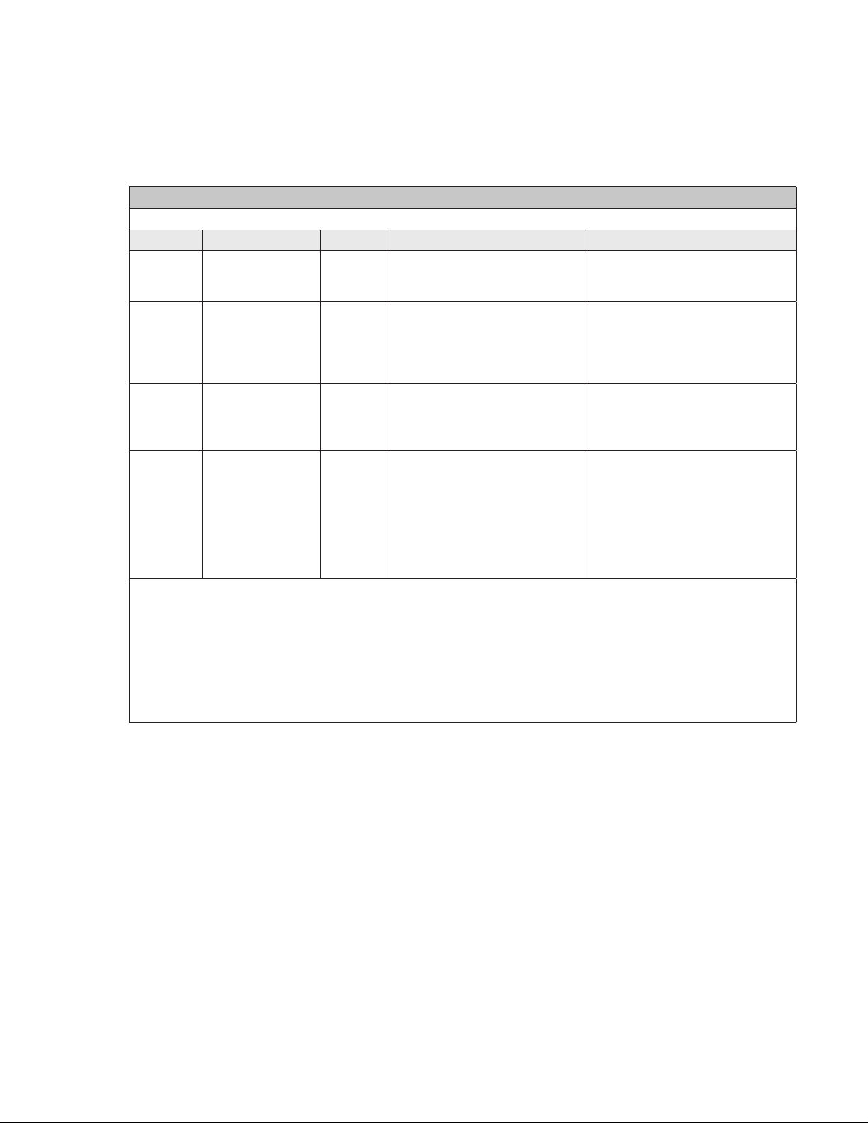
Appendix C:
The following commands can be used in Actions to control how a FrontRow CM3000 amplifier/switch handles audio:
CM3000 Audio Commands*
Syntax: #AUDn[Input,Mute,Volume];
Name Required/Optional Data Type Format Description
n Required Constant 1 Denotes the sub-device. Since
Input Optional Variant ICommand
Mute Optional Variant MCommand
Volume Optional Variant VCommand
Examples:
Unmute and increase volume: #AUD1[M0,V+];
Unmute and decrease volume by 2 steps: #AUD1[M0,V-2];
Set volume to 10% of maximum: #AUD1[V10];
Mute: #AUD1[M1];
Unmute: #AUD1[M0];
Toggle mute: #AUD1[M+];
Switch to input 3, unmute, and set volume to 25 of maximum: #AUD1[I3,M0,V25];
Query current settings (returns value of input, mute, and volume): #AUD1[];
CM3000 Commands
CM3000 has only one sub-device,
this is always 1.
Switches the audio input to:
• the channel corresponding to
where Command is an integer
from 1 to 4, +, or -
where Command is 0, 1, or +
where Command is an integer
from 1 to 100, +, or -. The + or
- may be followed by a single
digit (1-9) indicating the change
in volume steps to be made.
the integer used;
• the next higher channel (+); or
• the next lower channel (-)
Audio mute:
• off (0);
• on (1); or
• toggle (+)
Sets the audio volume to:
• the percentage of maximum
volume corresponding to the
integer used;
• an increase in volume (+) by n
steps (+n); or
• a decrease in volume (-) by n
steps (-n)
*For complete programming guidance, refer to the Calypso Action Control Language (CACL) manual under the
Resources tab of the ezRoom web page: www.gofrontrow.com/products/frontrow-ezroom
33
Page 37
Appendix D:
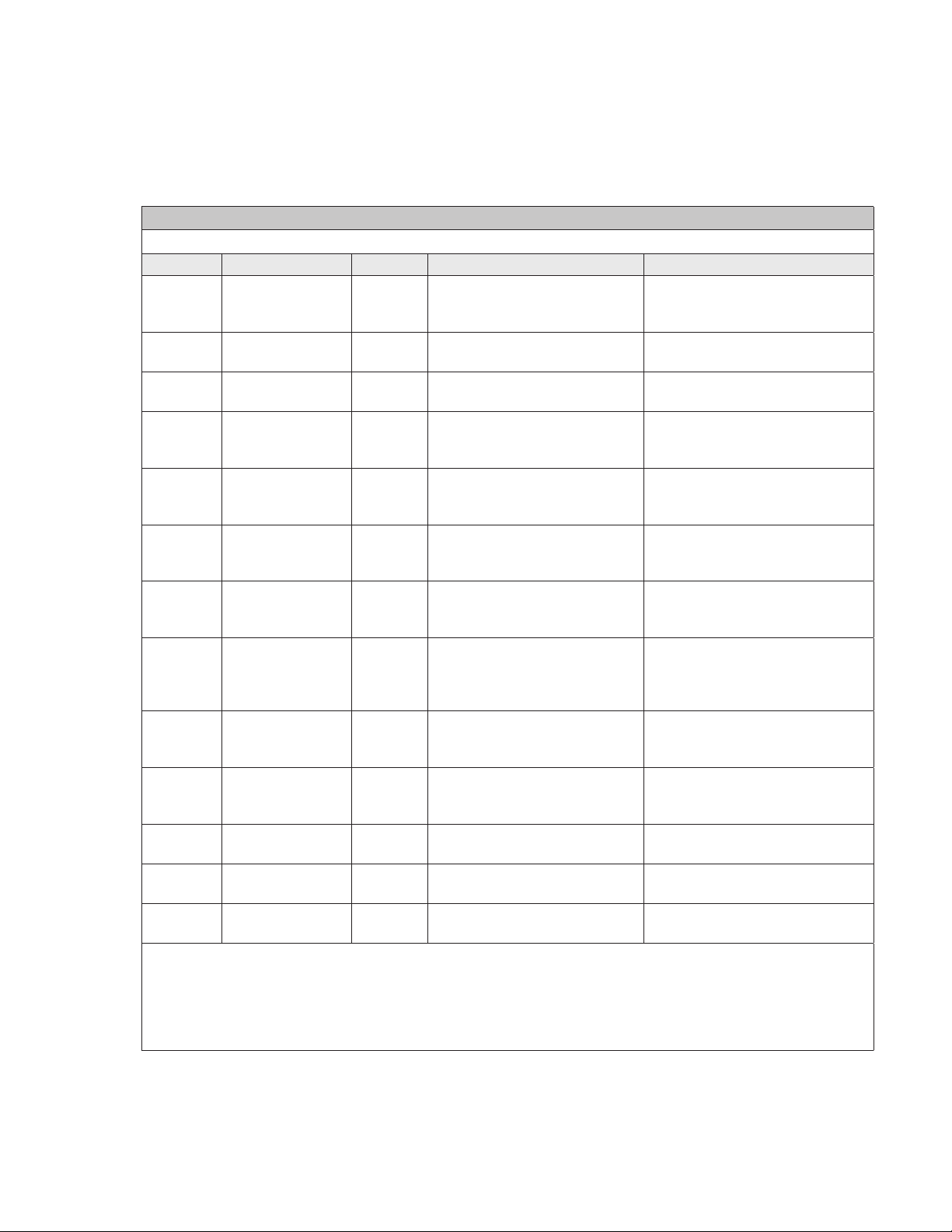
The following commands can be used in Actions to control how a FrontRow CA1000 amplifier handles audio:
CA1000 Audio Commands*
Syntax: #Command\r
Name Required/Optional Data Type Format Description
Command Required Variant ACHn
Examples:
Switch to input 3: #ACH3\r
Switch to next lower input channel: #ACR\r
Unmute and increase volume: #BVI\r
Unmute and set volume to 14: #BVA14\r
Mute: #AVM0\r
CA1000 Commands
Switches the audio input to the
where n is an integer from 1 to 4
ACF Switches the audio input to the
ACR Switches the audio input to the
AVIn
where n is an integer from 1 to 2
AVDn
where n is an integer from 1 to 2
BVIn
where n is an integer from 1 to 2
BVDn
where n is an integer from 1 to 2
AVMn
where n is blank, 0, or 1
AVAn
where n is an integer from 1 to
32
BVAn
where n is an integer from 1 to
32
AVA? Queries current volume level.
ACH? Queries current input channel.
AVM? Queries current mute status. Re-
channel corresponding to the
integer used
next higher channel
next lower channel
Increases volume by n steps. If
you leave the argument n blank, a
default of 1 is assumed.
Decreases volume by n steps. If
you leave the argument n blank, a
default of 1 is assumed.
Unmutes and increases volume by
n steps. If you leave the argument
n blank, a default of 1 is assumed.
Unmutes and decreases volume by
n steps. If you leave the argument
n blank, a default of 1 is assumed.
Audio mute:
• on (0);
• off (1); or
• toggle (blank)
Sets absolute volume to level
indicated by n.
Unmutes and sets absolute volume
to level indicated by n.
Returns integer from 1 to 32.
Returns integer from 1 to 4.
turns 0 or 1.
*For complete programming guidance, refer to the Calypso Action Control Language (CACL) manual under the
Resources tab of the ezRoom web page: www.gofrontrow.com/products/frontrow-ezroom
34
Page 38
Appendix E:
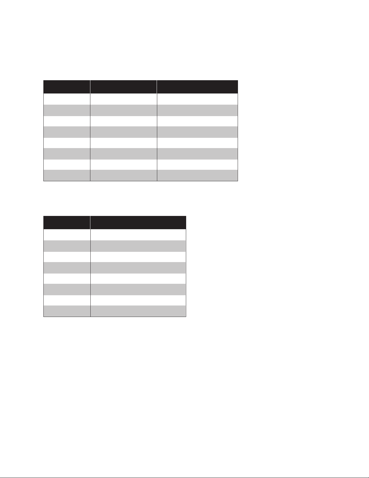
I/O Port Pin Out
Pin # Wire Color Function
1 Orange TX1
2 Brown TX2
3 Red RX1
4 White RX2
5 Black GND 1 (IR or GPI)
6 Yellow GND 2 (Power)
7 Blue IR Out+ or GPI
8 Green 12V or 9V
LAN RJ-45 Pin Out
Pin-Out Guide
Pin # Function
1 TX+
2 TX-
3 RX+
4 GND_Ethernet power
5 GND_Ethernet power
6 RX-
7 +12_Ethernet power
8 +12_Ethernet power
35
Page 39

Appendix F:
I’ve connected a new CB2000 to my computer for configuration but can’t communicate with it
• If you are using a Windows® computer, clear the ARP cache. From the command prompt,
enter: ARP -D IPADDRESS (e.g., ARP -D 192.168.1.104)
I’ve already programmed a CB2000 but can’t find the IP address
• Download the SpyGlass app from http://gofrontrow.com/en/products/frontrow-ezroom, under the Resouces tab.
Troubleshooting
36
Page 40
Installer Assistance: www.gofrontrow.com
USA/Global
FrontRow
Corporate Headquarters
1690 Corporate Circle
Petaluma, CA 94954-6712
toll-free: 800.227.0735
tel: 707.769.1110
fax: 707.769.9624
Canada
FrontRow
6950 Creditview Road, Unit 1
Mississauga, ON L5N 0A6
toll-free: 800.340.9894
tel: 905.461.5300
fax: 905.677.7760
web: www.gofrontrow.com
New Zealand
Oticon New Zealand Ltd.
142 Lambton Quay
P.O. Box 9128
Te Aro. Wellington
toll-free: 800 OTICON
toll-free fax: 00800 FAX OTICON
web: www.oticon.co.nz
web: www.gofrontrow.com
Australia
Phonic Ear
629 Nudgee Road
Nundah QLD 4012
Australia
freecall: 1 800 PHONIC
fax: 1300 737 983
web: www.gofrontrow.com.au
Scandinavia
Phonic Ear A/S
Kongebakken 9
2765 Smørum
Denmark
tel: +45 3917 7101
fax: +45 3927 7900
web: www.gofrontrow.com
United Kingdom
PC Werth Limited
Audiology House
45 Nightingale Lane
London SW12 8SP
tel: 020 8772 2700
web: www.soundfield.info
www.phonicear.com
© 2014 FrontRow Calypso LLC Phonic Ear, FrontRow, Calypso and the names of Phonic Ear, Calypso, and FrontRow products are trademarks or registered
trademarks of FrontRow Calypso LLC in the U.S. and other countries.
821-2000-011/Rev. B 0114
 Loading...