

Page 1

Page 2

© 200 5 Phonic Ear Inc. Phonic Ear and the names of Phonic Ear prod ucts are trademark s or regi stered tradem arks of
Phonic Ear Inc. in the U.S. and other countries. Product specifications and accessories subject to change without notice.
XX X-XX X-XX X/Rev. X /4 083 080 6
u.s.a. 800.227.0735, then press 5 • canada 800.263.8700 • international +45 3917 7101
Page 3
user guide
925RS Speaker
925T Body-worn Transmitter
925H Handheld Transmitter
925C Transmitter Charger
Page 4

Page 5

Page 6

Page 7

Introduction . . . . . . . . . . . . . . . . . . . . . . . . . . . . . . . . . . . . . . . . . . . . . . . . . . . . . . . . . . . . . . . .1
Understanding Active Learning. . . . . . . . . . . . . . . . . . . . . . . . . . . . . . . . . . . . . . . . . . . . . . . .2
Chapter 1 Setup Tips
. . . . . . . . . . . . . . . . . . . . . . . . . . . . . . . . . . . . . . . . . . . . . . . . . . . . 3 - 5
Chapter 2 Operation Tips
. . . . . . . . . . . . . . . . . . . . . . . . . . . . . . . . . . . . . . . . . . . . . . . . 6 - 8
Chapter 3
Parts & Accessories . . . . . . . . . . . . . . . . . . . . . . . . . . . . . . . . . . . . . . . . . . . 9 - 10
Chapter 4 System Features
. . . . . . . . . . . . . . . . . . . . . . . . . . . . . . . . . . . . . . . . . . . . . 11 - 16
Chapter 5
System Set-up. . . . . . . . . . . . . . . . . . . . . . . . . . . . . . . . . . . . . . . . . . . . . . . . . . . 17 - 24
Chapter 6
Using your system. . . . . . . . . . . . . . . . . . . . . . . . . . . . . . . . . . . . . . . . . . . . 25 - 36
Chapter 7
Speaker Placement & Mounting . . . . . . . . . . . . . . . . . . . . . . . . . . . . . . . . 37 - 39
Chapter 8
Channel Mapping Tips . . . . . . . . . . . . . . . . . . . . . . . . . . . . . . . . . . . . . . . . . . . . . 40 - 41
Chapter 9
Troubleshooting. . . . . . . . . . . . . . . . . . . . . . . . . . . . . . . . . . . . . . . . . . . . . . . . . . .42 - 43
Chapter 10
Speaker Battery Replacement. . . . . . . . . . . . . . . . . . . . . . . . . . . . . . . . . . . . . . . . . . . 44
Chapter 11
System Specifications . . . . . . . . . . . . . . . . . . . . . . . . . . . . . . . . . . . . . . . . . . . . . .45 - 48
Chapter 12
Regulatory & Safety Information. . . . . . . . . . . . . . . . . . . . . . . . . . . . . . . . . . . . . 49 - 52
Contents
Page 8

Congratulations on the purchase of your new FrontRow To Go™ active learning
system!
You may have heard the term ‘sound field’ used to describe technology that improves
classroom acoustics. Your FrontRow system fits under this category, but we call it
an ‘active learning system’ because the benefits affect much more than just sound.
Active learning systems can help engage students, improve attentiveness to the
teacher, build learning success, reduce the achievement gap, foster control and
orderliness, improve test scores, and reduce vocal strain and fatigue for teachers.
Numerous studies show that classrooms using active learning enjoy better student
comprehension, increased student participation, better grades and fewer behavioral
referrals.
Read this manual carefully to become familiar with your system and to get the most
out of its many features and options.
1
Introduction
Page 9
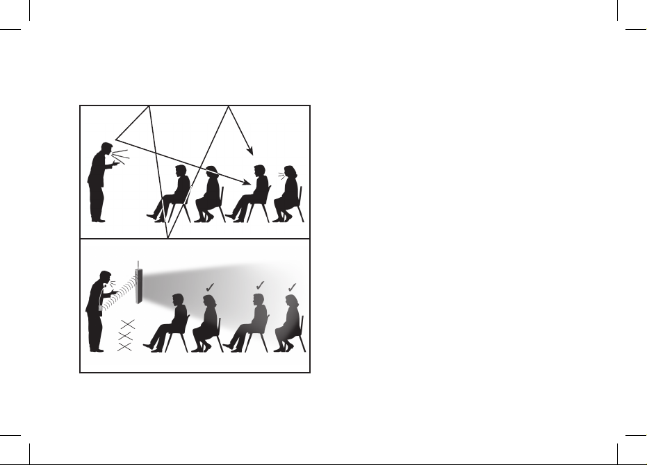
2
?
• dist ance
• noise
• echo
cough!
• dist ance
• noise
• echo
?
without active learning
with active learning
Understanding Active Learning and its Benefits
Page 10
3
IMPORTANT!
Be sure to charge your FrontRow ToGo speaker and transmitter units overnight – for
a minimum of 12 hours – before turning the power on and/or using them for the first
time. Failing to do so may reduce battery capacity.
Basic setup tips
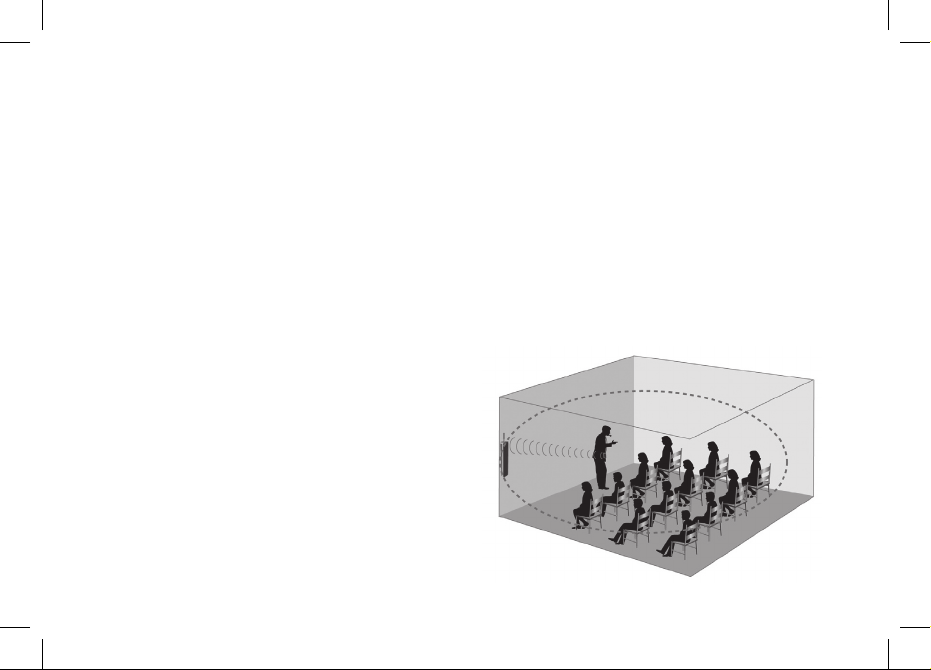
First – Identify a front corner of the room – the location from where the teacher
normally teaches.
Second – Take a good look around, paying
close attention to power outlet and other
electronic equipment locations. Ideally, the
speaker should be placed at a 5 ft./1.5m
distance from other electronic equipment,
such as computers or radios.
Third
– Determine whether to mount the
speaker on the wall as shown (diagram 1), or
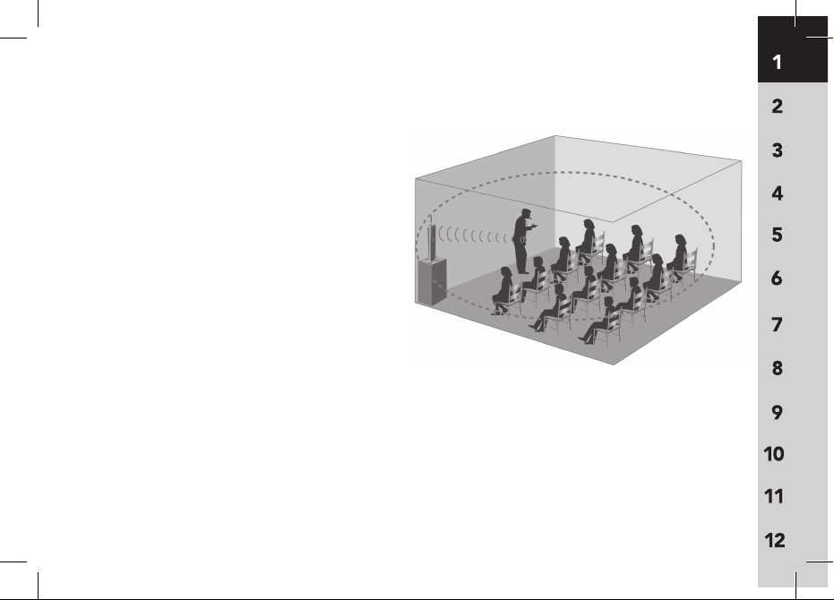
place it on a sturdy surface using the table
stand (diagram 2). In either case, the speaker
diagram 1
1 Setup Tips
Page 11
4
Setup Tips (cont’d)
should be placed at a height of 3 ft./1m
from the floor, or at a level closest to the
listener‘s ears.
Fourth – Consider whether other
FrontRow ToGo, FrontRow Tempo, or
other radio-based active learning systems
are in use in the building, and set transmitter and receiver channels accordingly.
Every transmitter in a building should
be on its own channel. See diagrams on
pages 40-41 for guidance.
If placing the speaker on a table or surface top,
consider the following:
• Choose a location that provides easy access for the teacher, and is out of
the way of students and main traffic areas. The speaker should be placed at
least 6 ft./1.8m away from where the teacher stands.
diagram 2
Page 12

5
• Choose a table or surface top that is sturdy. Make sure the table or cabinet is
structurally solid, sturdy and out of the way of foot traffic.
• Properly mount and securely fasten the table stand onto the bottom of the
speaker. Make sure the stand is fully open and screwed on tightly, and that the
speaker does not wobble when in an upright position.
If mounting on the wall, consider the following:
• The power supply cord needs to reach the wall outlet. Make sure the power
supply is within reach of the speaker in its wall-mounted position.
•
The teacher should be able to reach the controls located on top of the speaker
once it’s mounted. Once the volume is set at a comfortable level, the speaker
power switch located on the lower right side of the speaker can be easily accessed
by the teacher. Follow the instructions on page 32 for setting the volume at the
proper level.
• Never mount the speaker upside down, or horizontally.
The speaker unit must
be mounted so the controls are located at the top of the unit.
Setup Tips (cont’d)
Page 13

In the morning –
• Turn transmitter power ’on’ and put microphone on.
• Turn speaker column power ’on’.
The speaker should remain plugged into
a wall power outlet during the day – with the power in the ‘on’ position. Turn
power switch to the ‘off’ position at night after each use. The internal battery is
not being used while the speaker is plugged into a wall outlet.
• To operate using the internal battery as a portable system,
simply unplug
the speaker before use and plug back in after use. The battery takes 8 hours
to reach a full charge; at full charge, the speaker column battery will last up to 5
hours unplugged.
After each use –
• Turn transmitter power ’off’, and place it back onto the charging stand; con-
firm that the ‘charge’ indicator light illuminates. Transmitters not in use should
always be placed on the charging stand.
• Turn speaker column power ’of
f’. Leave speaker plugged into wall power out-
let, but confirm that the power has been turned ‘off.’
6
2 Operating Tips
Page 14

7
Battery care and maintenance tips –
• The speaker battery will last approximately 2 years depending on usage.
• When not in use, leave speaker plugged into wall outlet with power switch in
‘off’ position.
• Keep speaker away from heating units – use/store in a cool dry place.
• When using speaker battery power (unplugged from wall), always remember to
return power switch to ‘off’ position after use.
• Never mount/use speaker horizontally or upside down. Controls should be acces
-
sible from top of unit.
• Remember to charge all rechargable batteries overnight before initial use.
• Plan on buying new NiMH batteries for your transmitter every 12 months. Alkaline
batteries can also be used as back-ups, however, the 925C charger will not charge
alkaline batteries. Never attempt to charge alkaline batteries – this will cause
damage to the unit and void the product warranty.
Operating Tips (cont’d)
Page 15

8
Do not coil the microphone cord – since it also acts as your antenna, coiling
or wrapping the cord around the transmitter will affect its range and may also
reduce its life.
Speak at a normal level – the system is projecting your voice for you!
Operating Tips (cont’d)
Page 16
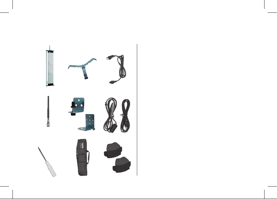
9
1
2
4 7
8
3 6
5
Receiver
1 Column Speaker Receiver
(925RS-216)
2 Receiver Antenna
(AT0831)
3 Channel Changer Screwdriver
(330-3000-101)
4 Speaker Table Stand
(890-88-320-00)
5 Wall Mounting Bracket (Set of 2)
(890-88-322-0 0)
6 Carrying Case
(895-88-025-00)
7 Power Cord, Receiver
(300-7402-110)
8 Audio Cable Kit - Aux Input/Output
(392-88-108-00)
9 Volume Locks (x2)
(543-88-020-00)
3 Parts & Accessories
9
Page 17
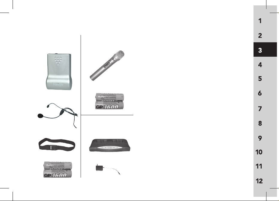
10
925T
1 Body-worn Transmitter
(925T-216)
2 Behind The Neck Microphone
(890-88-300-00)
3 Elastic Belt
(AT0712)
4 AA Rechargeable NiMH Batteries
(AT0807)
925H
1 Handheld Transmitter
(925H)
2 AA Rechargeable NiMH Batteries
(AT0807)
925C
1 Charging Stand
(925C)
2 Power Supply, Transmitter Charger
(AT0819)
1
3
2
4
2
1
1
2
925C
925H925T
Parts & Accessories (cont’d)
Page 18
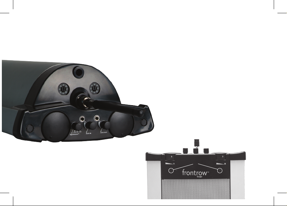
11
7
6
2
4
8
5
3
12
1
9
10
1. Channel A Channel Selector
2. Channel B Channel Selector
3. Antenna
4. Channel A On/Off/Volume
5. OptiVoice Selector
6. Aux-In Jack (3.5mm Mono)
7. Aux-In Volume
8. Aux-Out Jack (3.5mm Mono)
9. Aux-Out Volume
10. Channel B On/Off Volume
11. LED Indicators
12. Locator Hole
11
4 System Features: Receiver
Page 19
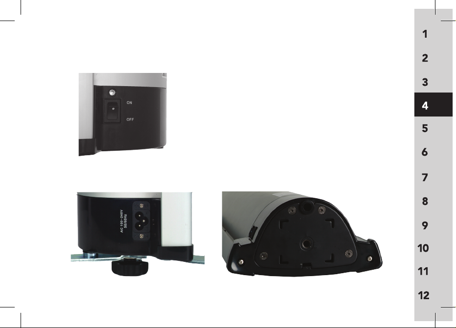
12
1. Speaker Battery Charge Indicator
2. Main Power On/Off Switch
3. Power Cord Jack
4. Locator Hole
5. Screw Hole
4
5
3
1
2
System Features: Receiver (cont’d)
Page 20
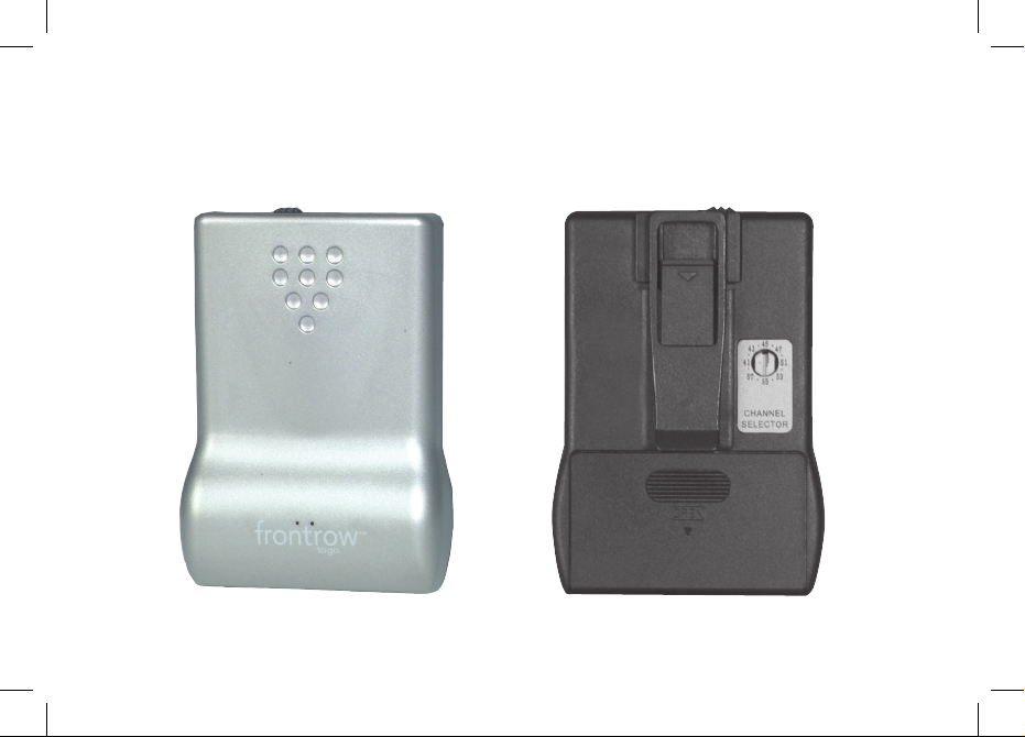
13
back
1
2
3
front
System Features: 925T
Page 21
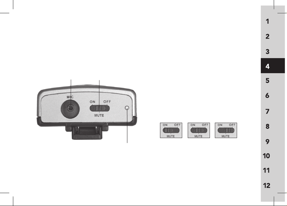
14
1. Belt clip
2. Battery compartment
3. Channel selector
4. Microphone input (2.5mm)
5. 3 position power switch
6. Power and low battery indicator light
On
Off
Mute
Top
4
5
6
System Features: 925T (cont'd)
Page 22
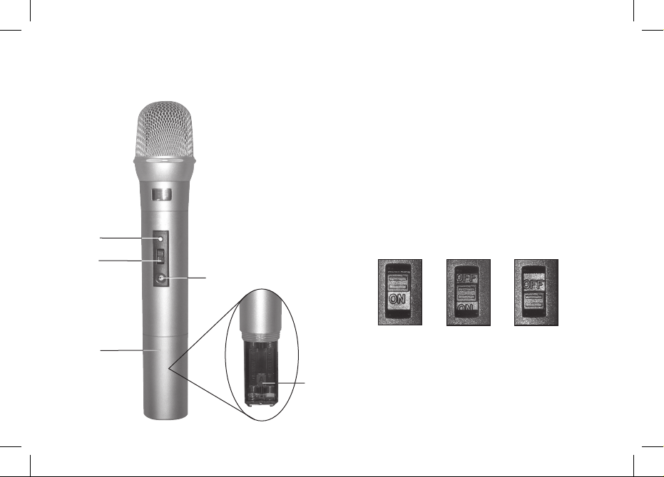
15
1. LED indicator light
2. 3 position power switch
3. Channel selector
4. Battery compartment
5. Channel selector key
(inside battery compartment)
On
OffMute
4
2
5
3
1
System Features: 925H
Page 23
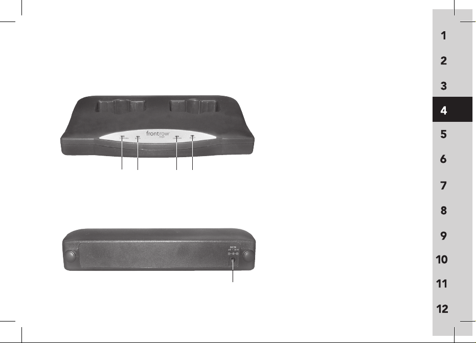
16
1. Pocket 1 charging indicator
2. Pocket 1 full charge indicator
3. Pocket 2 charging indicator
4. Pocket 2 full charge indicator
5. DC power jack
Front
Back
5
1
2 3 4
System Features: 925C
Page 24
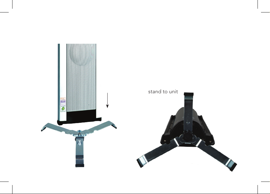
1. Place speaker unit face down on a
clean, flat surface
2. Open table stand arms
3. Place locator bolt of table stand into
locator hole on the bottom of
the speaker
4. Tighten fixing bolt to securely fix
stand to unit
17
5 System Setup: Receiver
Page 25
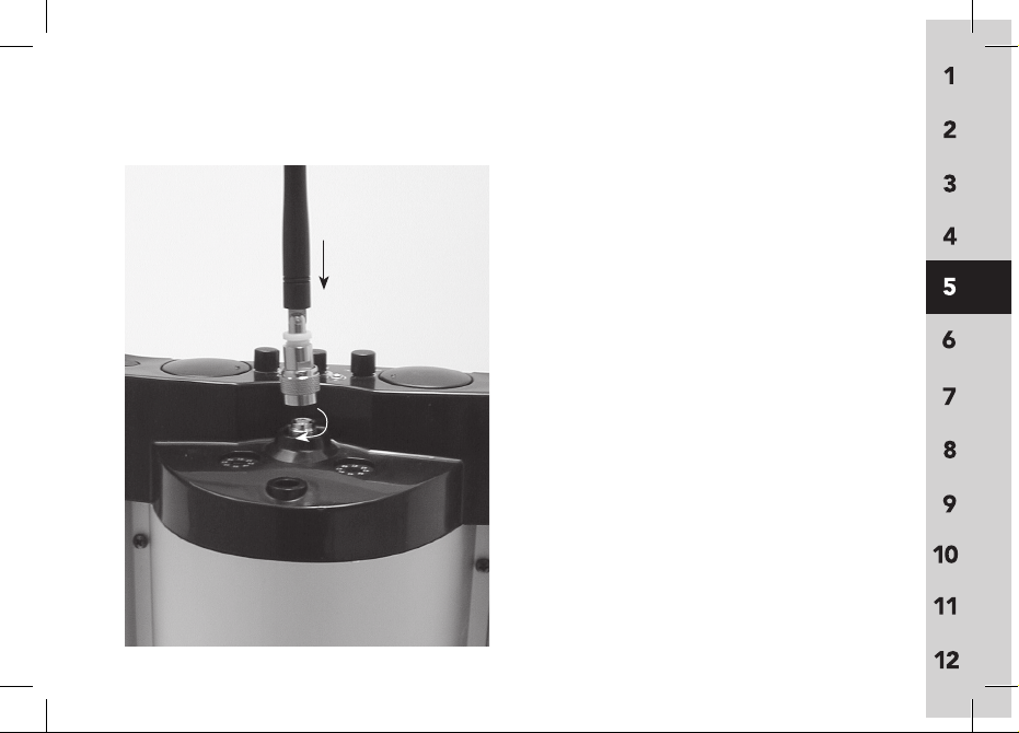
1. Attach antenna to top of speaker
2. Turn metal base of antenna
clockwise until secured tightly
(do not over-tighten)
1
2
18
System Setup: Receiver (cont’d)
Page 26
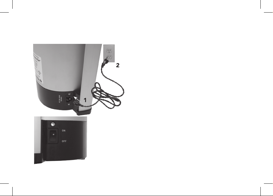
19
1
2
If using wall outlet:
1. Plug power cord into power jack
2. Plug power cord into wall socket
3. Turn speaker
off
System Setup: Receiver (cont’d)
3
Page 27
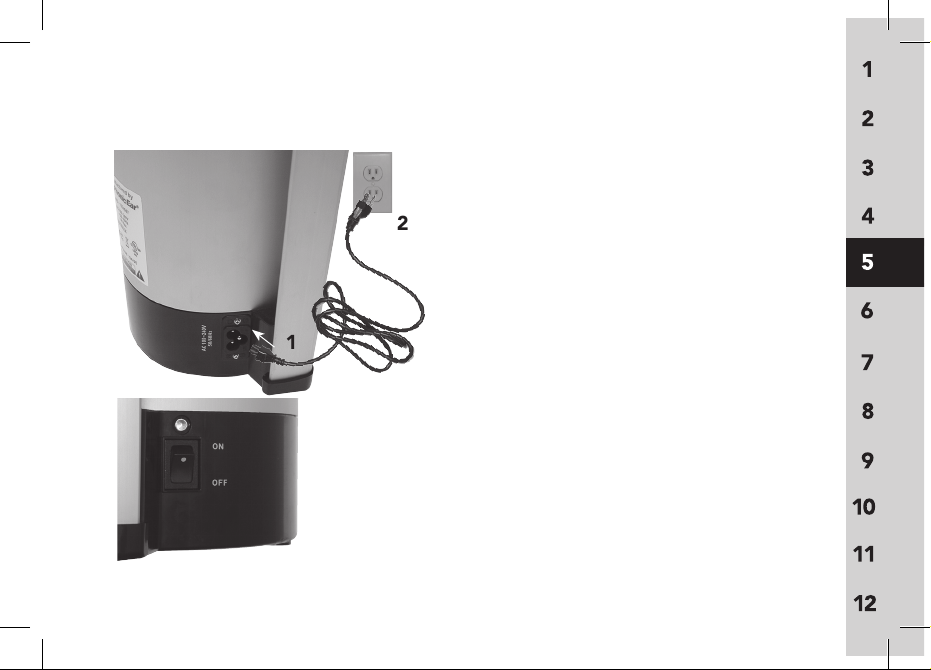
20
If using battery power:
1. Plug power cord into power jack
2. Plug power cord into wall socket
3. Turn speaker
off
Charge battery overnight before
initial use.
Red light =charging
Green light = fully charged
Recharging time is approximately
8 hours for a full charge.
NOTE:
Light is not illuminated during
battery operation
System Setup: Receiver (cont’d)
1
2
3
Page 28
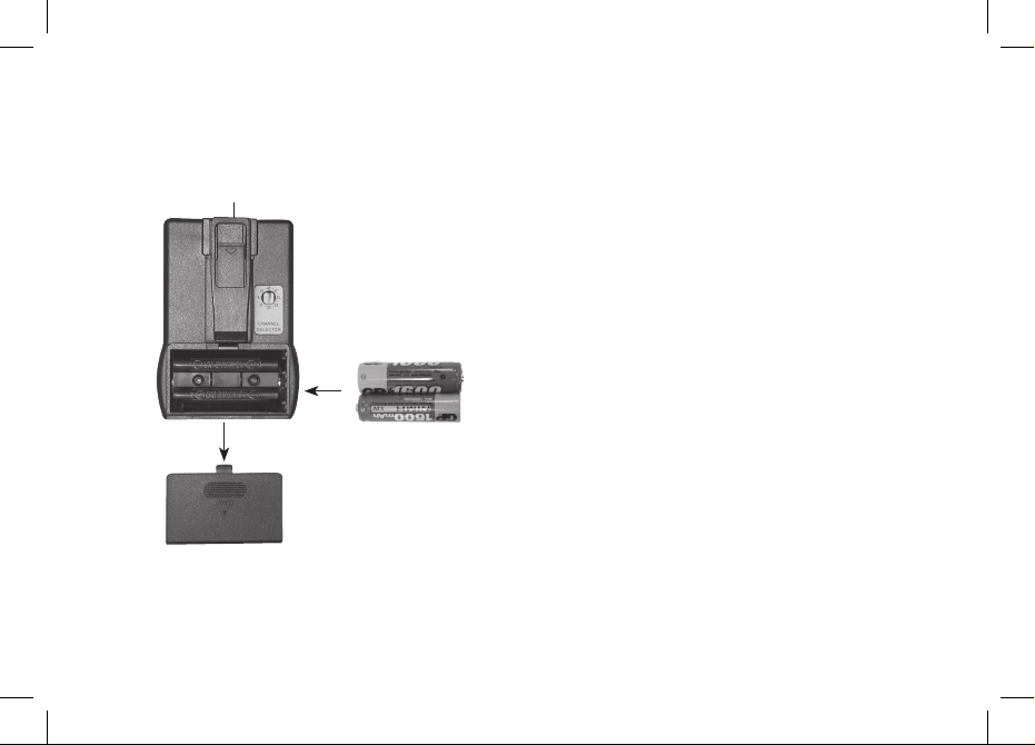
21
+
+
_
_
1. Switch power off
2. Remove battery cover
(push and slide off)
3. Insert two AA rechargeable
NiMH batteries
1
2
3
WARNING: Never recharge alkaline
batteries! This will cause
damage to the unit
and will void the product
warranty.
System Setup: 925T
Page 29
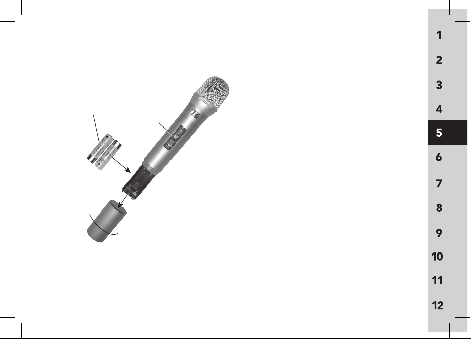
1. Switch power off
2. Remove battery cover
(turn counter-clockwise)
3. Insert two AA rechargeable
NiMH batteries
_
+
AA Rechargeable
NiMH batteries
_
+
1
3
2
22
System Setup: 925H
WARNING: Never recharge alkaline
batteries! This will cause
damage to the unit
and will void the product
warranty.
Page 30
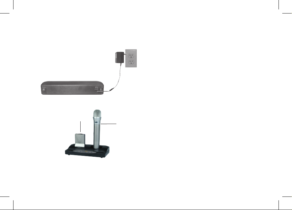
23
2
1. Plug power supply into power jack
on back of charger stand
2. Plug power supply into wall socket
3. Turn transmitters
off and place into
charger
charger back
charger front
3
3
1
System Setup: 925C
WARNING: Never recharge alkaline
batteries! This will cause
damage to the unit
and will void the product
warranty.
Page 31
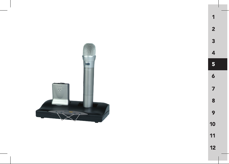
24
1. Charging:
Red light = units are being charged
Blinking red light = charging error.
Improper batteries have been
detected. Check your batteries and
replace as required. Only NiMH AA
batteries can be charged. Unit will
not charge disposable Alkaline
batteries or NiCad batteries.
2. Ready:
Green light = units are fully charged
1
2
System Setup: 925C (cont'd)
Page 32
25
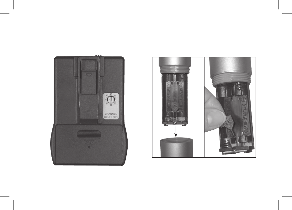
1. Open battery compartment door and
remove batteries
2. Remove channel adjustment key
2
1
925T 925H
6 Using Your System
Page 33
26
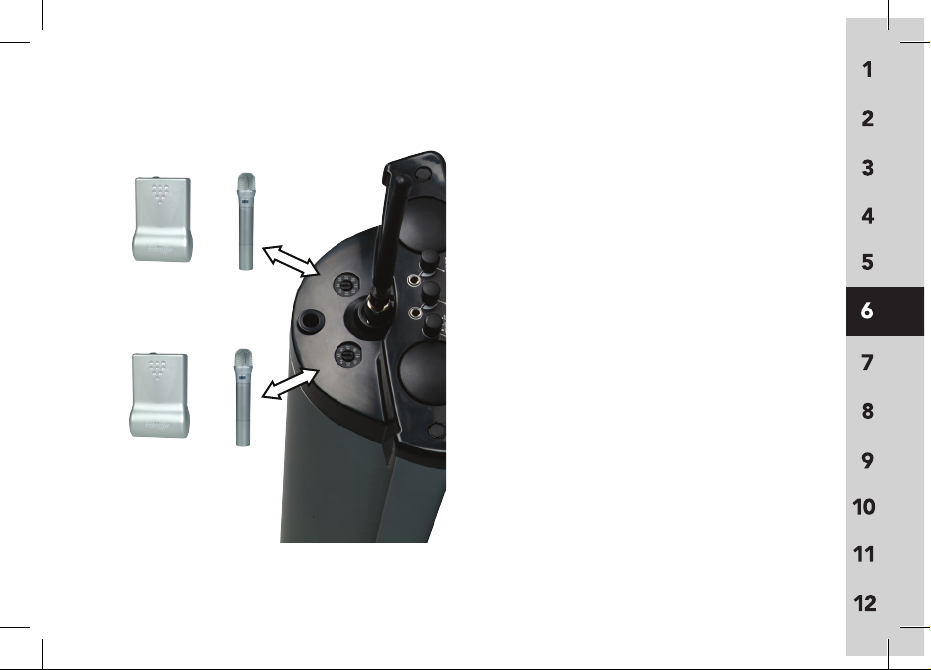
1. Use a screwdriver to turn frequency
selector to channel number that
matches the channel on column
speaker
2. If using both body-worn and hand-held
transmitters set one transmitter channel
to match
Channel A on the speaker
column, and the other transmitter
channel to match
Channel B channel
on the speaker column.
NOTE: Never operate two transmitters on
the same channel or interference
will result.
Or
Or
Must Matc
h
Must Matc
h
Using Your System (cont’d)
2
1
2
1
Page 34
27
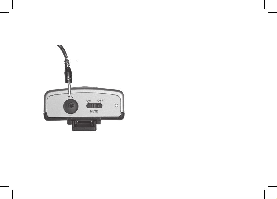
1.
Plug microphone cord into mic jack
on top of body-worn transmitter
Mic cord
1
Using Your System (cont’d)
Page 35
28
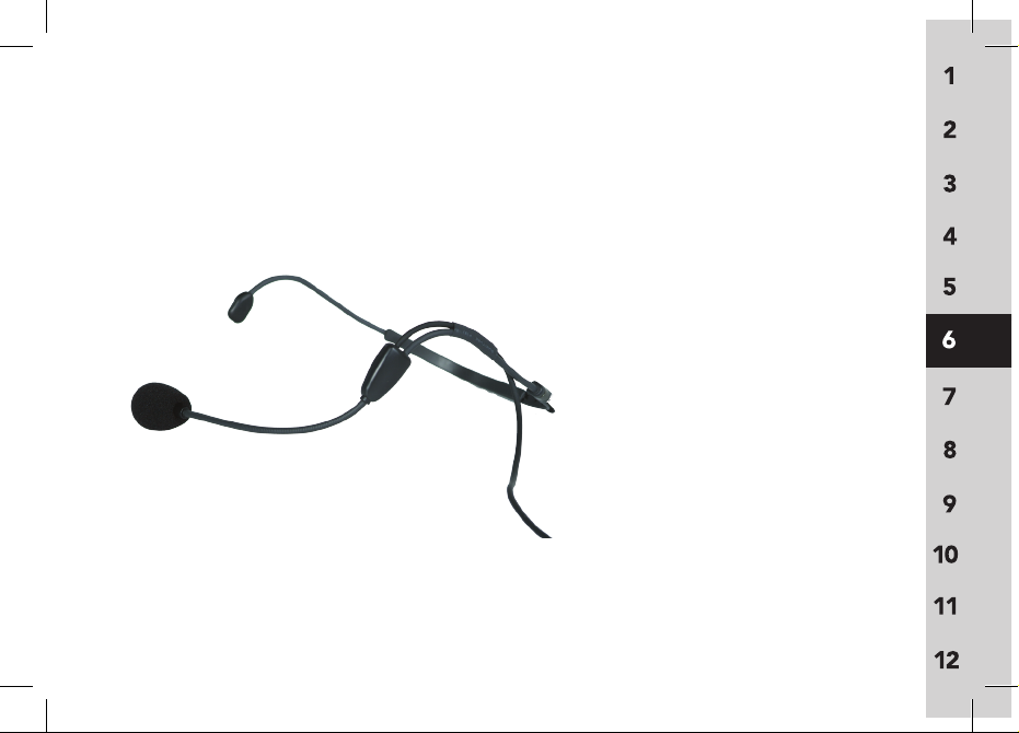
Put on microphone and adjust for proper
distance from mouth. Maximum distance
from mic to mouth is 6 in./15cm;
3 in./7.5cm is ideal.
Using Your System (cont’d)
Page 36
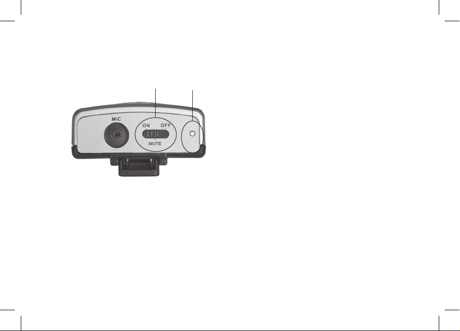
29
1. Switch power on
2.
Check indicator light:
Continuous green = adequate power
Continuous red = low battery
Battery Life
NiMH rechargeable AA = ~12 hours
Alkaline disposable A
A = ~15 hours
2
1
Using Your System (cont’d)
Page 37
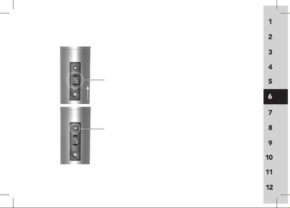
30
2
1
Using Your System (cont’d)
1. Turn power on
2.
Check indicator light:
Continuous green = adequate power
Continuous red = low battery
Battery Life
NiMH rechargeable AA = ~12 hours
Alkaline disposable A
A = ~15 hours
Page 38
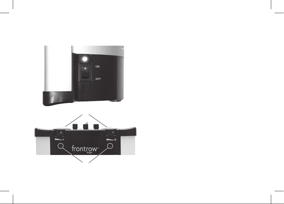
31
1. Turn main power on
2. Turn channel
on by turning Channel A
and/or
Channel B volume control
knob(s) (remember that main power
must also be on)
3. LED Indicators
Green = on & receiving FM signal
Red = on & NOT receiving FM signal
2
3
Using Your System (cont’d)
1
Page 39
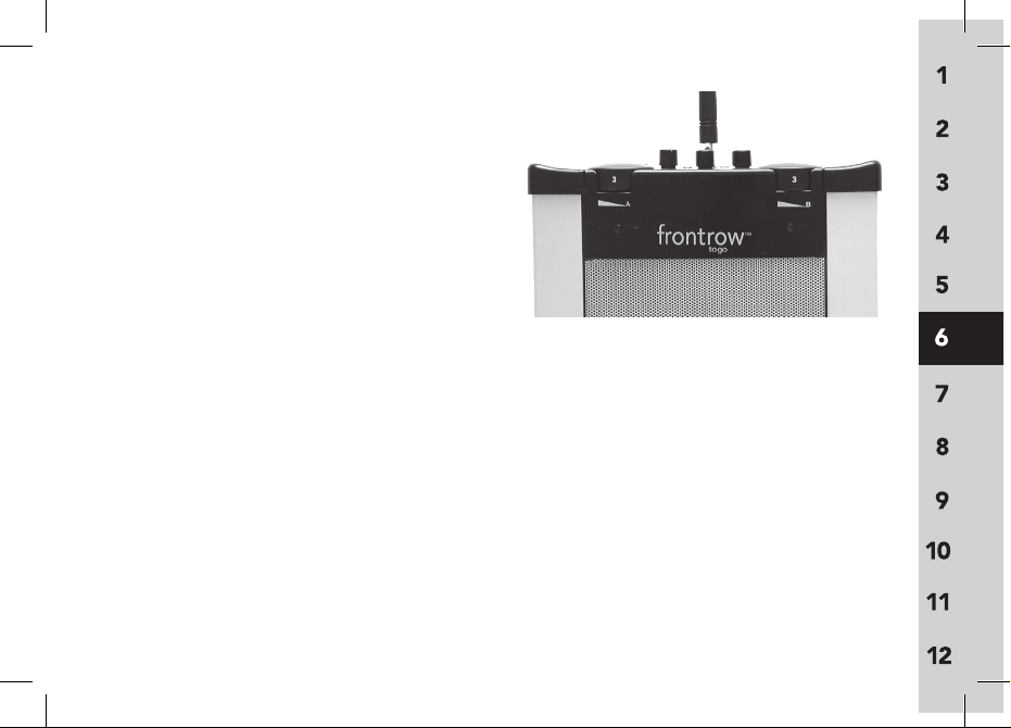
Follow steps 1 or 2 below to adjust
FM
volume setting to proper level. Two
people are needed to set the volume
level. It is difficult to hear your own voice
and make adjustments to it.
NOTE:
The average volume setting is
in the 3 position (see photo), but may
change depending on room acoustics and noise level.
1. With a sound level meter - Take a level reading in the center of the room during
normal classroom activity, and another reading of the teacher's amplified voice (without
the class activity). The level of the teacher's voice should be set between 10 - 15 decibels
above room noise level.
2. Without a sound level meter - First, ask someone other than yourself (if you are the
teacher) to listen to the amplified voice and make volume adjustments. An ideal volume
level is achieved when the listener can hear the amplified voice at a comfortable level and
the volume level from the speaker and teacher’s mouth is comparable. If you can hear
yourself through the loudspeakers, the volume setting may be too high and should be
decreased.
32
Using Your System (cont’d)
Page 40
Setting FM volume
33
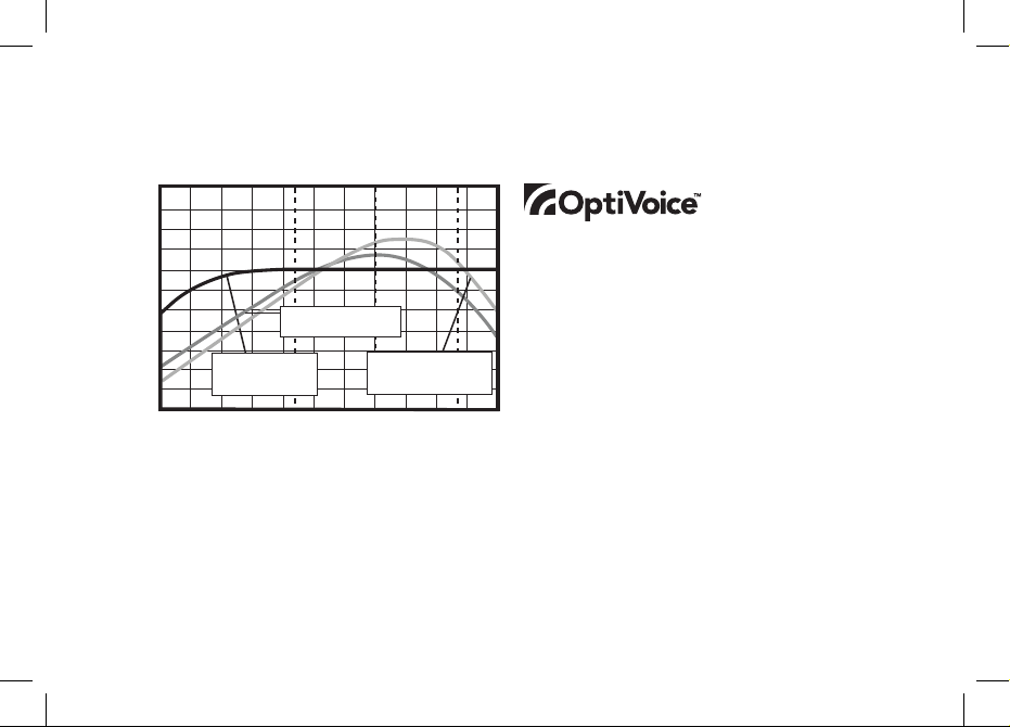
OptiVoice is a 3-position switch that
automatically adjusts the sound quality
of the primary speaker’s voice. It allows
teachers to shape the sound of their voice
and helps to ensure maxium speech clarity in low, medium and high noise levels.
Using Your System (cont’d)
10 20 30 50 100 200 500 1k 2k 5k 10k 20k
35
30
25
20
15
10
5
0
-5
-10
-15
-20
frequency (Hz)
dBv range
OptiVoice Settings and Speech Intelligibility
Critical speech intelligibility range (primarily consonants)
Lower frequencies provide warmth and personality but
can mask the higher frequencies critical to intelligibility
Contains little useful speech information
A
B
x
low position for
natural voice in
low noise levels
high position for
maximum intelligibility
in noisy conditions
medium position for
moderate noise levels
x
A B
x
Page 41
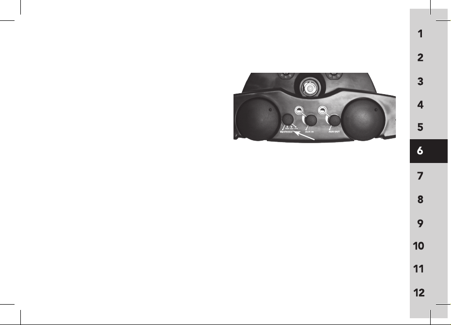
1. Set OptiVoice switch according to
room noise level. Medium position is the
recommended setting for average noise
levels.
Low: Use in low-noise situations and for
most natural voice reproduction.
Medium
: Best setting for average classrooms where low-medium noise levels are present.
High: Use in high noise levels. Helps to ensure top comprehension during critical tasks
such as test-taking or hearing impaired instruction.
NOTE: With each increase in level, there is an increase of approximately 3dB in gain
(volume). This may require a decrease in the receiver volume setting to avoid potential
microphone/speaker feedback.
34
Using Your System (cont’d)
Page 42
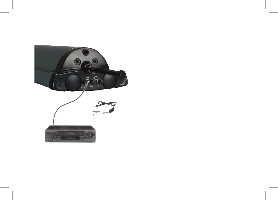
35
1. Using the appropriate adaptor cords,
connect VCR, TV, CD, computer or
other audio source to Aux-In port on
top of speaker.
2. Use Aux-In Volume control to
adjust volume
NOTE: Aux-In can be used simultane ously with both Channel A & B.
VCR
1
or
See Cable Kit for details
2
Using Your System (cont’d)
Page 43
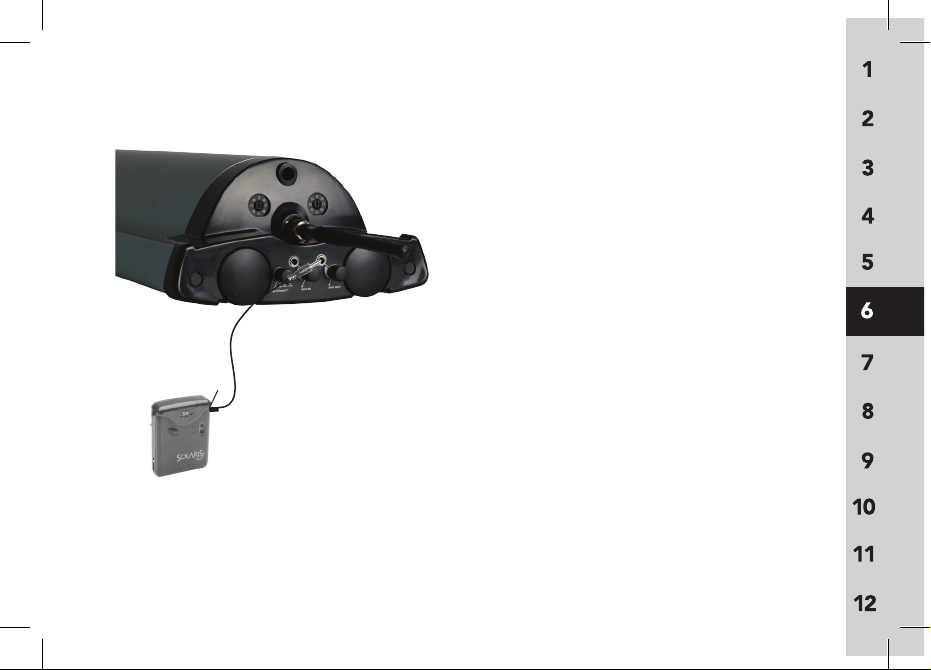
36
Aux out – connecting to personal FM
devices
Connecting to computer, recording
device or other transmitter
(for rebroadcast of audio to students with hearing
impairment)
1. Connect device to the Aux-out jack
using the appropriate cord.
2. Adjust output volume accordingly.
1
2
Aux In
Using Your System (cont’d)
Page 44
37
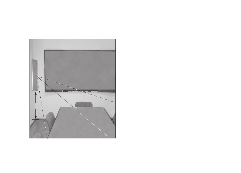
3ft./1m
Place speaker in a corner of the room facing listeners. Mount speaker on wall using
brackets or place speaker on a surface using
a speaker stand. The bottom of the speaker
should be about 3 ft./1m from the floor.
(See setup tips on page 3).
7 Speaker Placement & Mounting
Page 45
38
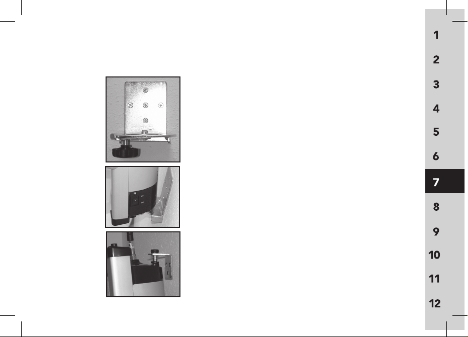
Without Mounting Template:
1.
Attach lower bracket to wall
– If mounting to drywall, use 5
screws with drywall anchors
2. Place speaker on lower bracket and hold
in place. Be sure the locator hole on
the bottom of the speaker is securely
mated with bolt in the lower bracket
3. Insert upper bracket into the locator
hole on the top of the speaker and
place against the wall. Do not depress
the spring on the upper bracket. Mark
the upper bracket holes, then carefully
remove the speaker from the bottom
bracket. Attach upper bracket to wall
Speaker Placement & Mounting (cont’d)
1
2
3
Page 46
39
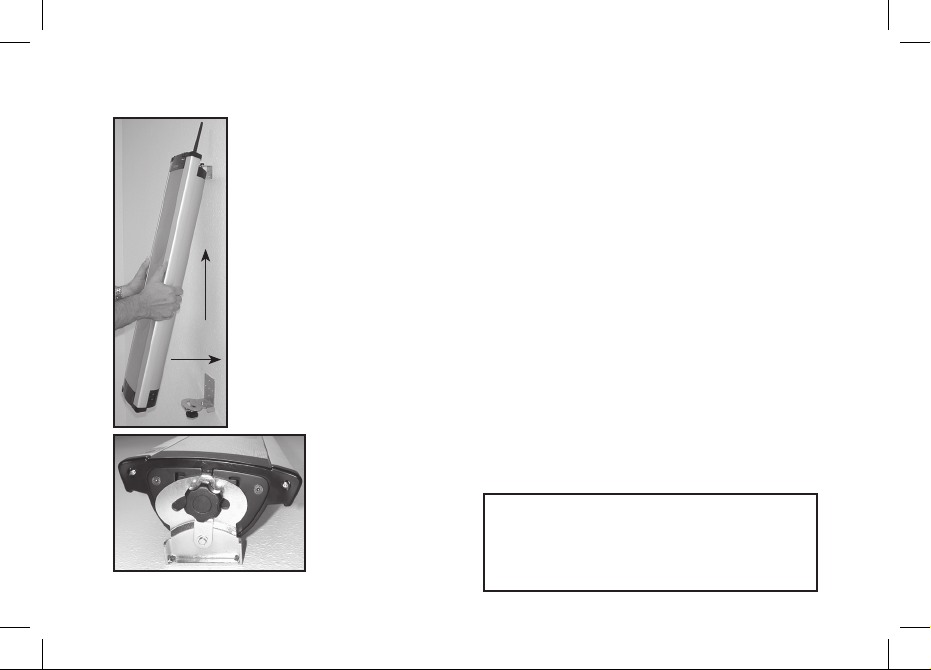
4. Attach speaker to wall mount by
inserting the upper bracket into the
locator hole in the top of the speaker.
Gently lift the speaker upwards and
forward, mating the locator bolt on the
lower wall mount bracket with the
locator hole on the bottom of the
speaker
5. Move swivel arm to align screw holes.
Screw in fixing bolt through the swivel
arm and into the screw hole in bottom
of speaker. Tighten.
To remove unit from wall mount, simply
unscrew the fixing bolt and lift the
speaker up and out.
Speaker Placement & Mounting (cont’d)
4
5
WARNING:
To prevent injur y, thi s app aratus mu st b e sec urel y
atta ched to the w all using the wall brackets and mou nting sc rews or with the floor stand supplied w ith the
purchase of this sys tem, b oth of which must be securely
fastened by the fi xing bolt.
Page 47
40
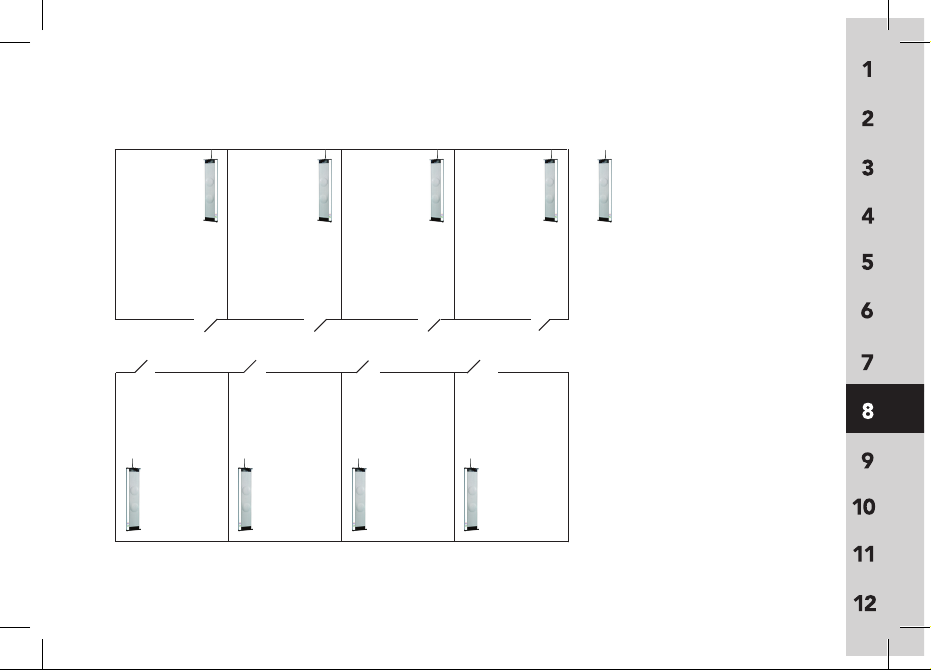
= suggeste d placement of
925RS-216 speaker
hallway
Cha nnel A: 44
Cha nnel B: 54
Cha nnel A: 41
Cha nnel B: 51
Cha nnel A: 46
Cha nnel B: 56
Cha nnel A: 42
Cha nnel B: 52
Cha nnel A:
48
Cha nnel B:
58
Cha nnel A:
45
Cha nnel B:
55
Cha nnel A:
47
Cha nnel B:
57
Cha nnel A:
43
Cha nnel B:
53
8 Channel Mapping Tips
Page 48
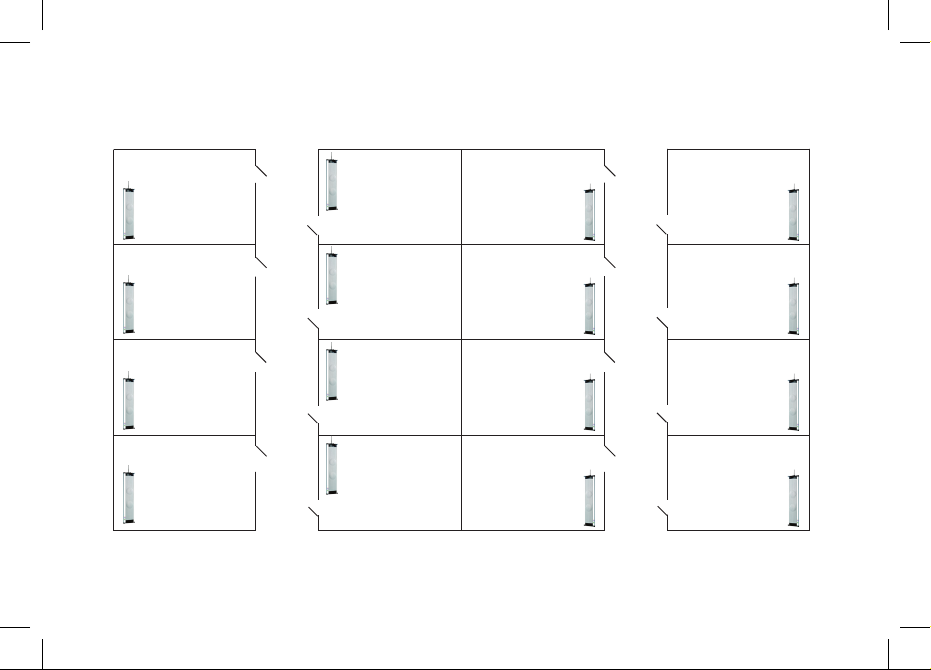
41
hallway
hallway
Cha nnel: 41
Cha nnel:
45
Cha nnel:
51
Cha nnel:
55
Cha nnel:
44
Cha nnel:
48
Cha nnel: 54
Cha nnel: 58
Cha nnel: 42
Cha nnel:
46
Cha nnel:
52
Cha nnel:
56
Cha nnel: 43
Cha nnel: 47
Cha nnel:
55
Cha nnel:
57
Channel Mapping Tips (cont’d)
Page 49

no FM reception (Channel A, Channel
B indicator does not have green light)
• Verify the transmitter is turned on
• Verify the frequency number on the
transmitter matches the frequency
number on receiver
• Verify transmitter batteries are
charged
• Verify speaker antenna is connected
properly
weak sound from speaker
• Increase volume on the speaker
• Turn up transmitter volume
• Make sure the boom microphone (or
other mic) is being worn correctly
speaker is receiving a signal but no
sound is coming out
• Verify microphone is connected
properly to transmitter and is working
correctly
feedback from speaker
• Turn down the volume on the
transmitter
• Turn down the volume on the speaker
• Make sure the person wearing the
transmitter is not too close to the
speaker
• Move speaker so that it is facing away
from presenter and toward listeners
• Make sure the boom microphone (or
other mic) is being worn correctly
42
9 Troubleshooting
Page 50

troubleshooting (cont’d)
speaker does not turn on
• Verify main power switch on the
bottom of the unit is turned on
• Verify Channel A and Channel B
volume control knobs are turned on
• Verify power supply is plugged
securely into speaker and wall socket
• Verify wall socket works
speaker battery does not charge
• Connect power supply to speaker
and charge for four hours. If speaker
battery does not hold a charge, contact FrontRow Service department
for replacement (battery should be
replaced after one year of continuous
use).
speaker is picking up FM interference
or hum
• Check to make sure no other wireless
systems are operating on similar frequencies
• Check to make sure the system is not
placed too close to a computer
• Check to make sure metal objects are
not placed too close to transmitter or
speaker
(i.e. jewelry, metal shelves)
yellow charge light is flashing when I
attempt to charge my transmitter
• Replace your batteries with a set of
new NiMH cells.
43
Page 51
44
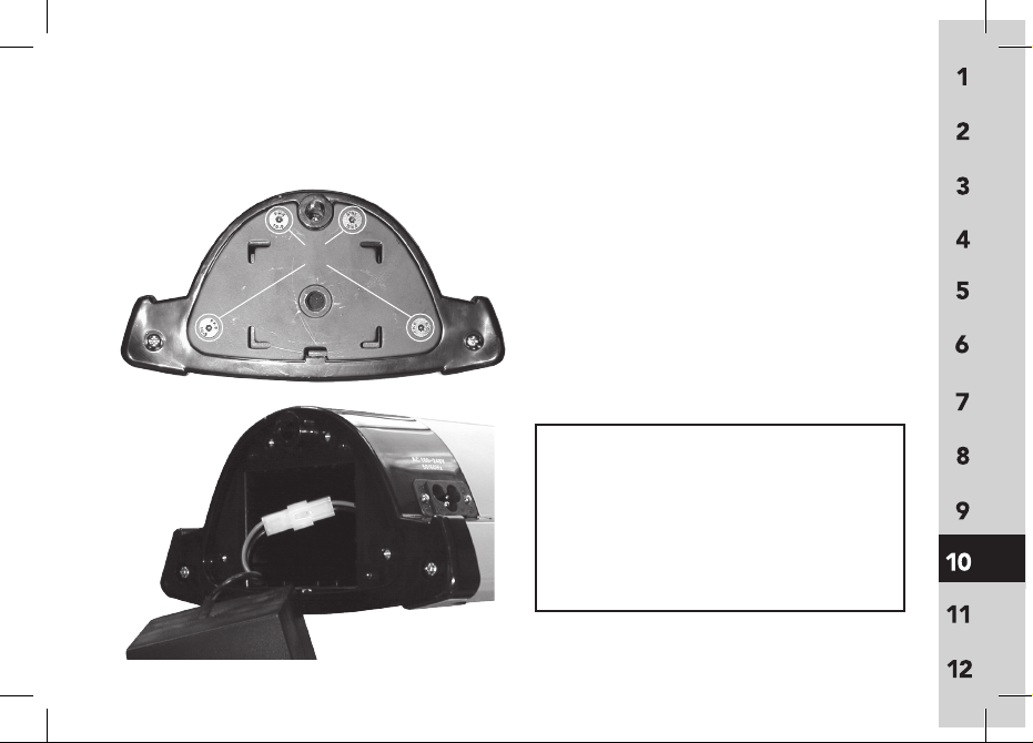
10 Speaker Battery Replacement
1. Turn off main switch and disconnect
the power cord from the wall outlet
and the rear base of the apparatus.
2. Remove 4 hex screws (3mm) on bottom
and remove panel
3.
Disconnect old battery and replace with
new battery. Replace panel and 4 hex
screws. Do not over tighten screws.
2
3
CAUTION:
Danger of ex plosion and damage to the receiver may
resul t if th e bat tery is incorrec tly replace d. Replace
only with th e recommended ty pe NiMH bat tery pack
sold by Front Row.
DISPOSAL/ENVIRONMENT:
Disposal of old ba tteries must be done in accordance
and with regards to all applic able and local environmental la ws, regulations and codes. Always d ispose bat teries in an environm entally safe manner.
Page 52
45
Channel # Channel A Channel # Channel B
41 . . . . . . . . . 216.025 MHz 51 . . . . . . . . . 216.525 MHz
42
. . . . . . . . . . 216.075 MHz 52 . . . . . . . . . 216.575 MHz
43
. . . . . . . . . . 216.125 MHz 53 . . . . . . . . . 216.625 MHz
44
. . . . . . . . . . 216.175 MHz 54 . . . . . . . . . 216.675 MHz
45
. . . . . . . . . 216.225 MHz 55 . . . . . . . . . 216.725 MHz
46
. . . . . . . . . 216.275 MHz 56 . . . . . . . . . 216.775 MHz
47
. . . . . . . . . 216.325 MHz 57 . . . . . . . . . 216.825 MHz
48
. . . . . . . . . .216.375 MHz 58 . . . . . . . . . 216.875 MHz
11 System Specifications
Page 53
46
two channel column speaker: 925RS-216
Carrier Frequency Range 216 - 217MHz
Modulation FM (F3E)
Output Power Maximum 36W RMS @ 4
Ω x 2
Power Requirements
AC 110-200V
~50-60Hz, 1A max
Battery 1 x NiMH rechargeable
Frequency Response 100Hz
– 9kHz (at rated output)
Total Harmonic Distortion <1% (at rated output) @ 1kHz
System signal-to-noise >70 dB (at rated output)
ratio
Inputs 1 x aux-in, 3.5 mm mono
Output 1 x aux-out, 3.5 mm mono
Controls
Channel A/B on/off/volume
Channel A/B channel selector
aux-in volume, aux-out
volume, OptiVoice
main power
Dimensions (w xhxd) 29.5 x 7.2 x 3.4 in
750 x 183 x 85 mm
Weight 12.5lbs. / 5.7 kg
Battery life 5 hours (rechargeable)
Recharging time 8 hours
System Specifications (cont’d)
Page 54

47
Body-worn Transmitter: 925T
Carrier Frequency Range 216 - 217MHz
Modulation FM (F3E)
Operating Range >110 ft./34m
RF Output <15mW
Total Harmonic Distortion <0.5%
Dynamic Range 100dB
D
imensions (wxh xd) 2.5 x 3.5 x 1 in.
65 x 90 x 25 mm
Weight 1.8oz / 51g
Controls
On/Mute/Off, Volume Control
Channel selector
Inputs/Outputs 2.5mm mic input jack
Batter y Type 2 A A (LR6) NiMH
rechargeable (1600mA) or
2 AA (LR6) alkaline disposable
Batter y life 12 hours (rechargable)
15 hours (alkaline)
Recharging time 6 hours
Carrier Frequency Range 216 - 217MHz
Modulation FM (F3E)
Operating Range >110 ft. / 34m
RF Output <15mW
Total Harmonic Distortion <0.5%
Dynamic Range 100dB
Dimensions (dia.xh) 2.1 x 9.3 in.
54 x 237 mm
Weight 8.1oz / 230g
Controls On/Mute/Off
Channel selector
Batter y Type 2 A A (LR6) NiMH
rechargeable (1600mA) or
2 AA (LR6) alkaline disposable
Batter y life 12 hours (rechargable)
15 hours (alkaline)
Recharging time 6 hours
System Specifications (cont’d)
Handheld Mic Transmitter: 925H
Page 55
48
Charging Stand: 925C
Power Supply AC adaptor (DC 12V / 0.5A)
Indicator lights Power = red LED
Charging = yellow LED
Ready = green LED
Charging Error = blinking yellow LED
Dimensions (w xhxd) 1.9 x 5.3 x 9 in
135 x 47 x 230 mm
Weight 12.7oz / 360g
System Specifications (cont’d)
Page 56

Transmitter
This transmitter is authorized by rule under
the Low Power Radio Service (47 C.F.R. Part
95) and must not cause harmful interference
to TV reception or United States Navy SPASUR
installations. You do not need an FCC license
to operate this transmitter. This transmitter
may only be used to provide: auditory assistance to persons with disabilities, persons who
require language translation, or persons in
educational settings; health care services to
the ill; law enforcement tracking services under
agreement with a law enforcement agency;
or automated maritime telecommunications
system (AMTS) network control communications. Two-way voice communications and all
other types of uses not mentioned above are
expressly prohibited.
This device may not interfere with TV reception
or federal government radar, and must accept
any interference received, including interfer-
ence that may cause undesired operation. Add
energy star copy here. Add energy star copy
here. Add energy star copy here. Add energy
star copy here. Add energy star copy here.
IMPORTANT NOTE: To comply with FCC
RF exposure compliance requirements, only
use supplied antenna that is sold with this
transmitter. Use of any other antenna which
has not been approved by the manufacturer
will violate FCC rules and regulation and void
the user’s authority to operate this device.
This device and its antenna(s) must not be colocated or operating in conjunction with any
other antenna or transmitter.
49
12 Regulatory
Page 57
50
This equipment has been tested and found
to comply with the limits for a Class B digital
device, pursuant to Part 15 of the FCC Rules.
These limits are designed to provide reasonable protection against harmful interference
in a residential installation. This equipment
generates, uses and can radiate radio frequency energy and, if not installed and used
in accordance with the instructions, may
FrontRow To Go Receiver/Speaker 925RS
Tested to comply with
FCC Standards
FOR HOME OR OFFICE USE
receiver: part 15, subpart B
cause harmful interference to radio communications. However, there is no guarantee that
interference will not occur in a particular installation. If this equipment does cause harmful
interference to radio or television reception,
which can be determined by turning the
equipment off and on, the user is encouraged
to try to correc t the interference by one or
more of the following measures:
• Reorient or relocate the receiving antenna.
• Increase the separation between the equipment and receiver.
• Connect the equipment into an outlet on a
circuit different from that to which the
receiver is connected.
• Consult the dealer or an experienced radio/
TV technician for help.
Regulatory (cont’d)
Page 58

51
Part 95
This transmitter is authorized by rule under
the Low Power Radio Service (47 CFR Part
95) and must not cause harmful inter fer-
ence to TV reception or United States Navy
SPASUR installations. You do not need
an FCC license to operate this transmitter. This transmit ter may only be used to
provide auditory assistance to persons with
disabilities, persons who require language
translation, or persons in educational settings; health care services to the ill; law
enforcement tracking service under agreement with a law enforcement agenc y; or
automated maritime telecommunication
system (AMTS) network control communications. Two-way voice communications and
all other types of uses not mentioned above
are expressly prohibited.
FCC notes
The FrontRow To Go active learning system is approved by the FCC (Federal
Communications Commission). The use of
the system may be governed by specific FCC
rules and FCC licensing or notifications may
be required. Consult your local FCC office
for detailed information.
Phonic Ear FM receivers and FM transmitters,
when required, are approved by the Federal
Communications Commission (FCC) in the
U.S. and Industry Canada. Other government
approvals are available upon request. (Other
international regulations may also apply.)
Any changes or modifications made to any
government-approved element of this instrument, without the express approval of Phonic
Ear Inc in writing, could void the user's
authority to operate those elements of the
system.
Regulatory (cont’d)
Page 59
52
This device may not cause interference
and must accept any interference received,
including interference that may cause undesired operation.
These devices may not interfere with TV
reception or Federal Government radar.
IC notes
This Class B digital apparatus complies with
Canadian ICES-003.
Cet appareil numérique de la classe B est
conforme à la norme NMB-003 du Canada.
The term "IC:" before the radio certification
number only signifies that Industry of Canada
technical specifications were met.
If TV channel 13 is used in the area, the
installer shall reduce or adjust the RF radiated power so that near-by TV channel 13
receivers do not receive radio interference
from the system installed. Suggestions: A test
Regulatory (cont’d)
with a T V receiver equipped with "rabbit-ear
antenna" and tuned to channel 13 should
be conducted, at the perimeter of the users'
intended coverage area and not
over-lapping other user's areas without the
latter's consent. If this does not solve the
problem, a channel near the 217 MHz edge
and not near 216 MHz should be tried.
This product has been cleared
by the U.S. Food and Drug
Administration for use by
persons with normal hearing and hearing
impairment.
FDA
Page 60

This information with regard to safety is
required according to IEC 60065:2001 and
references requirements found in ISO/IEC
Guide 37.
The following information regarding safety is
recommended:
1) Only use the grounded power cord
supplied with the speaker/receiver for
electrical safety of the end-user
2) DO NOT put flammable material in, on or
under the receiver/speaker.
3) DO NOT position the receiver/speaker
near propane or natural gas appliances.
4) DO NOT position the receiver/speaker
where it is likely to come into contact with
water
5) DO NOT position the receiver/speaker
higher than 3 feet off the ground
SAFETY INSTRUCTIONS & PRECAUTIONS:
53
6) Maintain distances around the receiver/
speaker for sufficient ventilation
7) Ventilation should not be impeded by
covering the receiver/speaker or its
openings with items, such as newspa pers, table-cloths, curtains, etc.
8) Dispose all used batteries in an environ mentally safe manner and never place
batteries in a fire or near a flame source
9) Do not expose the speaker/receiver to
extreme outdoor tropical or humid cli mates where environmental exposure
to heat and moisture could damage it
prematurely
10) Always store the receiver/speaker in a dry
environment when not in use.
Page 61

A) Terminals marked with the
are considered HAZARDOUS LIVE
and the external wiring connected to
these terminals requires installation by an
INSTRUCTED PERSON or the use of ready
made leads or cords.
B) The Front Row ToGo 925RS Receiver
Speaker is built with the following
electrical safety features:
• Short circuit protection
• AC input line fuse protection
ELECTRICAL SAFETY INFORMATION:
PRECAUTIONS & SAFETY
RECOMMENDATIONS
Follow Ma nufacturers' Recommendations
Before using the receiver, read all instructions
for, and caution markings on the receiver and
in this user guide.
54
Page 62

DANGER! RISK OF ELECTRICAL AND
FIRE HAZARD. MAY RESULT IN DEATH,
SERIOUS INJURY, SHOCK OR BURNS.
TO HELP REDUCE THIS RISK:
This receiver, like all elec trical products,
MUST be treated with respec t. Follow these
instructions to reduce electrical hazard risk.
1. PROPER GROUNDING AND
AC POWER CONNECTION
o The receiver MUST be grounded to
reduce risk of electric shock. The
receiver is equipped with an elec tric
cord having an equipment grounding
conductor and a grounding plug.
The plug MUST be plugged into an
outlet that is properly installed and
GROUNDED in accordance with all
local codes and ordinances. If you
ever feel even a slight shock from this
or any electrical appliance, stop, walk
away. Turn off electricity to outlet, and
ELECTRICAL WARNINGS:
have it inspected by an electrician.
You may have a dangerous,
improperly wired outlet.
o DANGER - NEVER alter AC power
cord or plug provided - if it will not
fit in the outlet, have proper outlet
installed by a qualified electrician
or proceed as shown in the illustra tion below. Improper connection
can result in a risk of an electric shock.
This battery the receiver is for use on a
nominal 120 volt circuit (common
household current), and has a ground ing plug as illustrated. A temporary
adapter may be used, USA only, to
connect this plug to a two-pole recep tacle, as shown, if properly grounded
outlet is not available. The temporary
adapter should be used only until a
properly grounded outlet can be
installed by a qualified electrician.
55
Page 63
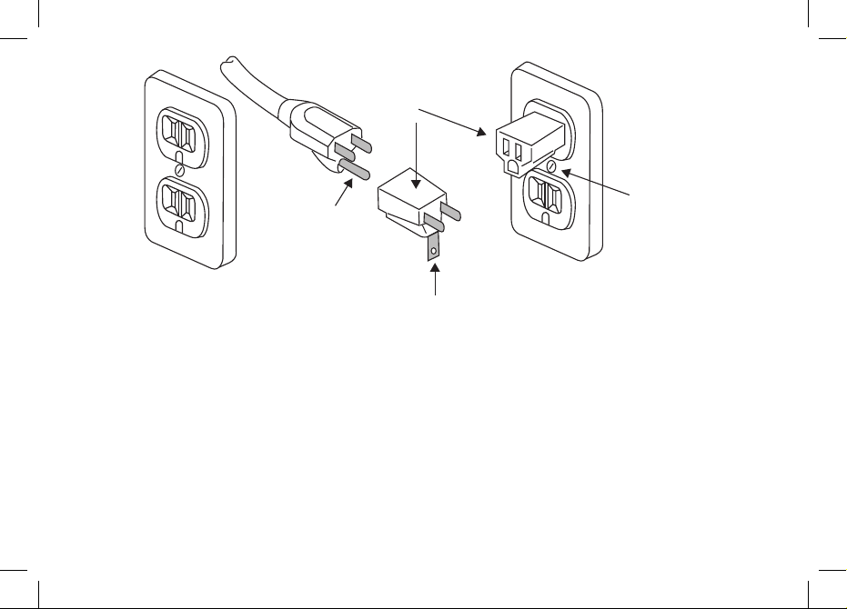
DANGER - Before using adapter as illustrated, be certain that center screw of outlet
plate is grounded. The green colored rigid
ear or lug extending from adapter MUST be
connected to a properly grounded outlet
- make certain it is grounded. If necessar y,
replace original outlet cover plate screw with
a longer screw that will secure adapter ear or
lug to outlet cover plate and make ground
connection to grounded outlet.
2. Avoid Abuse to the Receiver
o To reduce risk of electric shock, unplug
the receiver from outlet before
attempting any maintenance or clean ing. Turning off controls will not reduce
this risk.
o DO NOT disassemble the receiver.
Return the apparatus to Phonic Ear
Front Row for qualified service and
repair if service or repair is required.
56
Adpater
USA Only
Grounded outlet Grounded means
Grounding plug
with
Grounding pin
Two conductor outlet
center screw MUST be grounded
Grounded
center screw
Using an adpater is forbidden in Canada. If a grounded outlet is not available,
have one installed by a qualified elec trican before using this charger.
Page 64

57
Incorrect reassembly may result in a
risk of electric shock or fire.
o DO NOT expose the receiver to rain,
snow, water, gas, oil, etc.
o DO NOT operate the receiver if it has
received a sharp blow, been dropped,
or otherwise damaged in any way;
return the apparatus to Phonic Ear
Front Row for qualified service and
repair.
o DO NOT block or cover the apparatus
and impeded ventilation.
3. Proper Use of The receiver and Wiring
o An extension cord should not be
used unless absolutely necessary. Use
of improper extension cord could
result in a risk of fire and electric
shock. If extension cord must be
used, use ONLY a grounded, 3-wire
type cord. NEVER use a 2-wire cord
and an adaptor! The cord MUST be
plugged into a grounded outlet. Make
sure it is properly wired, in good elec trical condition, and wire size is large
enough for AC ampere rating of
the receiver as specified below.
AWG = American Wire Gauge
o To reduce risk of damage to plug
and cord when disconnecting the
receiver, ALWAYS pull on plug -
NEVER on cord.
o Locate cord so that it will not be
stepped on, tripped over, or other wise subject to damage or stress. DO
NOT lay extension cord on battery or
the receiver. DO NOT operate the
receiver with damaged cord or plug replace them immediately.
ELECTRICAL WARNINGS: (cont'd)
Page 65

58
Notes
Page 66

59
Notes
Page 67

60
Notes
Page 68

Notes
61
 Loading...