

Page 1
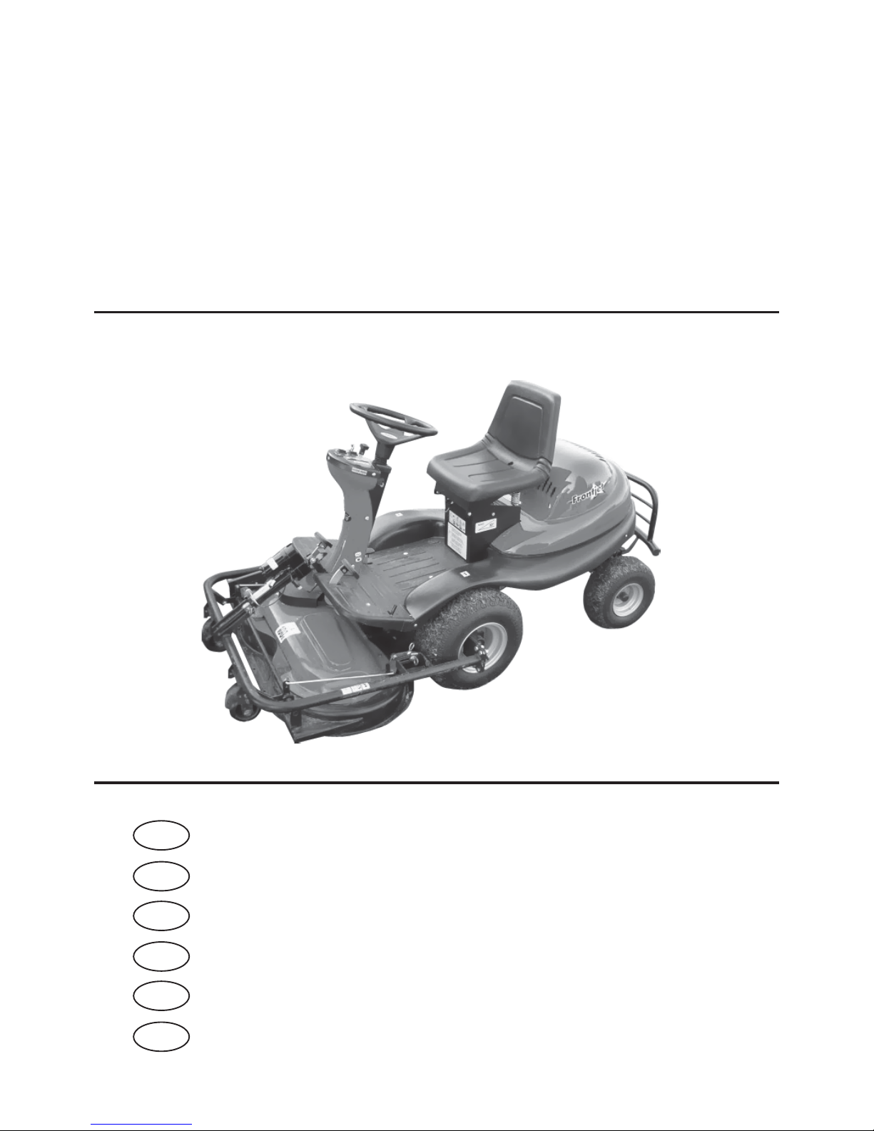
Samojízdný žací stroj
Mowing machine
Rasentraktor
Rider falciatutto
Faucheuse automotrice
Åkklippare
AP 105
Návod k použití
Operator’s manual
Bedienungsanleitung
Manuale di istruzione
Mode d’emploi
Handbok
FRONTJET 2006
CZ
EN
FR
DE
IT
SV
Page 2
2
Česky ........................................................................ 1
English ...................................................................... 23
Deutsch .................................................................... 45
Italiano ...................................................................... 67
Français .................................................................... 89
Svenska ....................................................................111
Page 3

1
OBSAH
Es prohlášení o shodě ..........................................................2
Předmluva ...........................................................................3
1. Ochrana a bezpečnost zdraví při práci ................4
1.1 Bezpečnostní pokyny ...........................................4
Gra cké zobrazení výstrah a upozornění ........... 5
1.1.1 Práce na svahu ......................................................5
1.1.2 Neprovádějte ........................................................5
1.1.3 Bezpečnost dětí ....................................................5
1.1.4 Požární bezpečnost ..............................................5
2. Použití a technický popis .....................................6
2.1 Použití stroje ........................................................6
2.2 Technický popis ................................................... 6
2.2.1 Rám stroje ............................................................6
2.2.2 Motor včetně elektroinstalace .............................. 6
2.2.3 Převodová skříň včetně pohonu předních kol .....6
2.2.4 Zadní náprava s koly včetně řízení ......................6
2.2.5 By-pass..................................................................6
2.2.6 Kapotáž a místo obsluhy ..................................... 6
2.2.7 Žací ústrojí ...........................................................6
2.3 Označení ...............................................................6
3. Technické parametry ........................................... 7
4 . Vybalení................................................................8
4.1 Kontrola po vybalení ...........................................8
4.1.1 Likvidace obalu ....................................................8
4.2 Příprava pro uvedení do provozu ........................ 8
4.2.1 Montáž volantu .................................................... 8
4.2.2 Montáž sedadla ....................................................8
4.2.3 Nastavení polohy sedadla .................................... 8
4.2.4 Připojení akumulátoru ........................................8
5. Uvedení do provozu .............................................9
5.1 Kontrola hladiny oleje v motoru ......................... 9
5.2 Kontrola akumulátoru .........................................9
5.3 Naplnění nádrže benzínem .................................. 9
6 . Ovládání stroje ................................................... 10
6.1 Popis a funkce ovladačů ..................................... 10
6.1.1 Spínač žacího ústrojí .......................................... 10
6.1.2 Spínací skříňka ................................................... 10
6.1.3 Páčka plynu ........................................................10
6.1.4 Sytič ....................................................................10
6.1.5 Počítadlo motohodin ......................................... 10
6.1.6 Spínač zvedání žacího ústrojí ............................11
6.1.7 Brzda ..................................................................11
6.1.8 Páka parkovací brzdy ......................................... 11
6.1.9 Pedál pojezdu ..................................................... 11
6.1.10 Páka by-passu ..................................................... 12
6.1.11 Páka nastavení výšky žacího ústrojí ..................12
6.2 Provoz a obsluha ................................................ 12
6.2.1 Nastartování motoru..........................................12
6.2.2 Zastavení motoru ............................................... 12
6.2.3 Zapnutí a vypnutí žacího ústrojí .......................13
6.2.4 Nastavení výšky žacího ústrojí ........................... 13
6.3 Pojezd .................................................................13
6.4 Rychlost pojezdu a sečení trávy .........................13
6.5 Jízda na svahu ..................................................... 13
7 . Údržba stroje ......................................................14
7.1 Přehled kontroly a údržby .................................14
7.2 Kontrola tlaku pneumatik .................................14
7.3 Údržba po práci .................................................. 14
7.3.1 Čistění ................................................................14
7.3.2 Mytí ....................................................................14
7.4 Údržba akumulátoru..........................................15
7.5 Údržba motoru ................................................... 15
7.5.1 Kontrola hladiny oleje v motoru ....................... 15
7.5.2 Výměna oleje ...................................................... 15
7.5.3 Výměna palivového ltru ..................................15
7.5.4 Údržba vzduchového ltru ................................ 15
7.5.5 Údržba zapalovací svíčky ................................... 15
7.6 Mazání ................................................................15
7.7 Výměna pojistky ................................................. 16
7.8 Nadzvednutí stroje ............................................. 16
7.9 Výměna nožů žacího ústrojí .............................. 16
7.9.1 Ostření nožů .......................................................16
7.10 Údržba řízení .....................................................16
7.11 Kontrola a seřízení řemenu pohonu pojezdu .... 17
7.12 Kontrola a seřízení klínových
řemenů pohonu žacího ústrojí ........................... 17
7.13 Vyjmutí žacího ústrojí ze stroje .........................17
7.14 Seřízení ozubeného řemenu pohonu nožů ........17
7.15 Výměna řemenů .................................................18
7.16 Výměna kola ....................................................... 18
7.17 Údržba hydrostatické převodovky ..................... 18
7.18 Seřízení brzdy ....................................................18
7.19 Přehled utahovacích momentů
šroubových spojů ...............................................18
8. Odstraňování poruch a závad ............................ 19
8.1 Objednávání náhradních dílů ............................20
8.2 Záruka ................................................................20
9. Posezóní údržba, odstavení stroje ..................... 21
10. Likvidace stroje .................................................. 21
Page 4

2
ES PROHLÁŠENÍ O SHODĚ
dle: Směrnice Rady č.98/37/EC (nařízení vlády NV 24/2003 Sb.)
Směrnice Rady č.89/336/EEC (nařízení vlády NV 18/2003 Sb.)
Směrnice 2000/14/EC (nařízení vlády NV 9/2002 Sb.)
A. My: Seco GROUP a.s., Pobřežní 44/362, Praha 8
odštěpný závod 02 AGS Jičín, Jungmannova 11
IČO: 60193450
vydáváme na vlastní zodpovědnost toto prohlášení:
B. Strojní zařízení
- název: Samojízdný žací stroj
- typ : AP 105
Popis:
AP 105 je čtyřkolový samojízdný žací stroj s motorem Briggs & Stratton 17,5HP. Pohon od motoru je přenášen klínovým
řemenem k pojezdové převodovce s plynule měnitelným převodem a přes elektromagnetickou spojku k žacímu ústrojí. Sečení je
dvounožové s vertikální osou rotace a šířkou záběru 1050 mm. Posečená hmota je rozprostřena na zem.
C. Předpisy, s nimiž byla posouzena shoda:
ČSN EN ISO 12 100-2, ČSN EN 55 012, EN 836+A1,2,3, ČSN ISO 4254-1, ČSN EN ISO 11 201, ČSN EN ISO 3767-1,3
D. Posouzení shody bylo provedeno postupem stanoveným v:
- Směrnice rady č. 98/37/EC, Článek 8, odstavec 2 a
)
, (eqv. §3, odst. 1 a), NV č. 170/1997 Sb.)
- Směrnice rady č. 89/336/EEC, Článek 10, odstavec 1, (eqv. §4, odst. 1, NV č. 169/1997 Sb.)
- Směrnice 2000/14/EC, Příloha VIII
E. Potvrzujeme, že:
- toto strojní zařízení defi nované uvedenými údaji je ve shodě s požadavky uvedenými ve výše uvedených technických
předpisech a je za podmínek obvyklého použití b e z p e č n é.
- jsou přijata opatření k zabezpečení shody všech výrobků uváděných na trh s technickou dokumentací a požadavky
technických předpisů.
- garantovaná hladina akustického výkonu je 100 dB(A)
Naměřené průměrné hodnoty akustického výkonu dle použitých motorů:
MOTOR Otáčky (min-1) Naměřená hodnota ak. výkonu [dB(A)]
Briggs & Stratton 17,5 HP INTEK 2700±100 98,32
Technická dokumentace v rozsahu dle přílohy V ke směrnici 98/37/EC a 2000/14/EC je uložena u výrobce na adrese:
Seco GROUP
odštěpný závod 02 AGS
Jungmannova 11
506 48 Jičín
Ing. Petr Fischer
místopředseda představenstva
V Jičíně dne 1.4.2005
Page 5

3
PŘEDMLUVA
Vážený zákazníku,
děkujeme Vám srdečně za Vaše rozhodnutí a volbu nákupu našeho stroje. Firma Seco GROUP a.s. jako nástupnický
majitel podniků Knotek a spol., Agrostroj a AGS Jičín je uznávána na evropských i světových trzích jako výrobce
kvalitních strojů značky AGS pro údržbu travnatých ploch.
Naším cílem bylo navrhnout a vyrobit vysoce kvalitní, výkonný stroj na sečení trávníků. Jsme přesvědčeni, že pokud
jste již měl možnost vyzkoušet si kvalitu práce stroje, budete souhlasit, že se nám podařilo splnit náš cíl.
Teď už záleží pouze na Vás, jakým způsobem budete s tímto strojem pracovat, aby Vám co nejdéle sloužil k Vaší
spokojenosti.
Prostudujte si pečlivě tento návod. Postupujte přesně podle pokynů v něm uvedených, abyste si usnadnili nejen
používání zakoupeného stroje, ale také zajistili jeho optimální využívání a dlouhou životnost.
Používejte tento samojízdný žací stroj jen k tomu účelu, ke kterému byl zhotoven. Jakékoliv použití neuvedené
v tomto návodě může být nebezpečné a může vést k poškození stroje. To může mít za následek neuznání záruky,
protože výrobce se v takovém případě vzdává veškeré zodpovědnosti.
V našich více jak 100 autorizovaných, kvalitně vybavených servisech po celé Evropě jsou Vám k dispozici servisní
odborníci, kteří byli proškolení a přezkoušeni ve výrobním podniku.
Page 6

4
1. OCHRANA A BEZPEČNOST ZDRAVÍ PŘI PRÁCI
Samojízdný žací stroj typu AP 105 s obchodním názvem FRONTJET je vyráběn podle platných evropských norem
o bezpečnosti.
1.1 BEZPEČNOSTNÍ POKYNY
Před prvním použitím Vašeho žacího stroje si pečlivě přečtěte návod k jeho obsluze. Při práci se žacím strojem důsledně dodržujte
bezpečnostní předpisy uvedené v tomto návodu. V případě, že stroj byl používán v rozporu s pokyny a informacemi uvedenými
v tomto návodu nebo se zákonnými ustanoveními, výrobce stroje nepřebírá žádnou zodpovědnost za případné škody a uživatel
ztrácí právo na záruční opravu.
Výstraha !
V případě nedodržení bezpečnosti práce je tento samojízdný žací stroj schopen useknout ruce, nohy či
vymrštit předměty a může tak dojít k vážnému poranění. Nedávejte ruce ani nohy pod kryt žacího ústrojí.
Nikdy se nepřibližujte žádnou částí svého těla k rotujícím nebo pohybujícím se součástem stroje.
Nepoužívejte stroj, je-li poškozeno nebo chybí-li některé z jeho ochranných zařízení. Veškeré kryty a jiná ochranná zařízení musí
být stále na svém místě. Neodstraňujte proto nebo nevyřazujte žádné ochranné zařízení stroje z činnosti. Kontrolujte pravidelně
funkce těchto zařízení.
Na stroji a jeho příslušenství nesmí být prováděny žádné technické změny bez písemného souhlasu jeho výrobce. Neoprávněné
změny mohou vést k hazardním podmínkám bezpečnosti práce a ke zrušení záruky.
Neměňte seřízení regulátoru motoru nebo omezovače otáček motoru.
Neodstraňujte ze stroje bezpečnostní nálepky a štítky.
Před uvedením stroje do provozu se důkladně seznamte se všemi jeho ovládacími prvky a zvládněte manipulaci s nimi tak, abyste
v případě nutnosti mohli stroj okamžitě zastavit nebo vypnout jeho motor.
Udržujte stroj a jeho příslušenství vždy v čistotě a dobrém technickém stavu.
Stroj smí řídit pouze osoba starší 18-ti let seznámená s tímto návodem k použití.
Stroj nesmí být použit k práci na svazích se sklonem větším než 14° (25%).
Uživatel stroje je odpovědný za bezpečnost osob, které se nachází v pracovním prostoru stroje.
Nepohybujte se v blízkosti stroje nebo pod ním, je-li zvednut a není ve zvednuté poloze dostatečně zajištěn proti spadnutí nebo
převrhnutí.
Přeprava dalších osob, zvířat a břemen přímo na stroji je zakázána. Přeprava břemen je povolena pouze na přívěsu, jehož typ je
schválen výrobcem stroje.
I při krátkodobém opuštění stroje vždy vyjměte klíček ze zapalování.
Pohybujete-li se strojem mimo pracovní prostor, v němž provádíte sečení, vždy vypněte žací ústrojí a zvedněte jej do transportní
polohy.
Je-li sečení vypnuto, musí být žací ústrojí vždy v transportní poloze.
Vypněte vždy žací ústrojí i motor a vyjměte klíček ze zapalování, když:
• čistíte stroj
• odstraňujete zanesení žacího ústrojí travou
• jste najeli na cizí předmět a je třeba zjistit, nedošlo-li k poškození stroje, popř. poškození odstranit
• stroj nepřirozeně silně vibruje a je třeba zjistit příčinu vibrací
• opravujete motor, nebo jiné pohyblivé části (odpojte i kabely od zapalovacích svíček)
Než začnete práci se strojem, odstraňte z plochy, na které budete sečení provádět, veškeré kameny, kousky dřeva, dráty, kosti,
padlé větve a jiné cizí předměty, které by mohly být při sečení odmrštěny.
Při práci se vyhýbejte krtčím hromádkám, betonovým podstavcům, pařezům, obrubníkům záhonů. a chodníků, které nesmí přijít
do kontaktu s noži a tím poškodit žací ústrojí a mechanismus stroje.
V případě nárazu na pevný předmět zastavte, vypněte žací ústrojí i motor a zkontrolujte celý stroj, zejména mechanismus řízení.
Je-li to potřeba, proveďte před novým nastartováním opravu.
Před dalším použitím odstraňte všechny závady. Před začátkem práce překontrolujte zejména napnutí řemenů, zejména ozubeného
řemene, nabroušení nožů a čistotu uvnitř výlisku sečení.
Rotační nože jsou ostré a mohou způsobit zranění. Při jakékoliv manipulaci s noži používejte ochranné rukavice nebo nože
obalte.
Kontrolujte pravidelně šrouby a matice upevňující nože a dbejte, aby byly dotaženy správným utahovacím momentem
(viz kapitola 7.19).
Věnujte zvýšenou pozornost samojistným maticím. Po druhém povolení matice je snížena její samojistící schopnost, proto je
nutné matici nahradit novou.
Kde je to možné, vyhněte se práci se strojem v mokré trávě.
Vyhýbejte se překážkám (např. náhlá změna sklonu svahu, příkopy atd.), na kterých by se stroj mohl převrátit.
Se strojem pracujte pouze za denního světla nebo při dobrém umělém osvětlení.
Se strojem se nesmí jezdit po veřejných komunikacích.
Při obsluze stroje nenoste volné oblečení a krátké kalhoty, používejte pevnou, uzavřenou obuv.
Nepracujte se strojem po požití alkoholu, drog či léků ovlivňujících vnímání.
Nepracujte se strojem, trpíte-li závratěmi, mdlodbami nebo jste-li jinak oslabeni či nesoustředěni.
Nenechávejte běžet motor v uzavřených prostorách. Výfukové plyny obsahují látky, které jsou bez zápachu a přitom jsou smrtelně
jedovaté.
Nestartujte motor bez výfuku.
Dodržujte všechny požadavky, týkající se požární bezpečnosti, uvedené v kapitole 1.1.4.
Hluk vznikající při sečení běžně nepřekračuje nejvyšší hodnoty akustického tlaku a akustického výkonu, uvedené v tomto
návodu v kapitole 3. „Technické parametry“. V některých případech však může za určitých podmínek a vlivem vlastností terénu
dojít ke krátkodobému zvýšení uvedené hladiny hluku. Výrobce stroje doporučuje při obsluze stroje používat chrániče sluchu,
protože při zatížení sluchového orgánu nadměrně vysokou hladinou hluku nebo dlouhodobým působením hluku hrozí trvalé
poškození sluchu.
Page 7

5
GRAFICKÉ ZOBRAZENÍ VÝSTRAH A UPOZORNĚNÍ
Nebezpečí Nesahat za provozu
Při opravě postupuj
dle návodu
Při jízdě neopouštěj
stroj
Odletující předměty
Přečíst návod
k použití
Nesekej v blízkosti
osob
Nikdy nevoz další
osoby
Nikdy nejezdi napříč
svahu
Držet nepovolané osoby
v bezpečné vzdálenosti
Rotační nože Nestoupat Nesahat – Možnost popálení Maximální pracovní sklon 14°
Výše znázorněné štítky a samolepky jsou připevněny na stroji.
1.1.1 PRÁCE NA SVAHU
Svahy jsou hlavní příčinou nehod, ztráty kontroly nad strojem či následného převrhnutí, které může vést k vážnému zranění i smrti.
Sečení na svahu vyžaduje vždy zvýšenou pozornost. Jestliže si nejste jisti, nebo je to nad Vaše možnosti, na svahu nesekejte.
Samojízdný žací stroj lze používat na svazích s max. sklonem do 14°(25%) a jen ve směru spádnice, tj. nahoru nebo dolů.
Není dovolena jízda po vrstevnici. Při změně směru je nutná zvýšená opatrnost. Neotáčejte se ve svahu, pokud to není nezbytně nutné.
Dávejte pozor na díry, kořeny, terénní nerovnosti. Nerovný terén může zapříčinit převrácení stroje. Vysoká tráva může zakrýt
skryté překážky. Odstraňte proto předem veškeré překážející předměty (viz předcházející kap. 1.1) z plochy, na které budete
sečení provádět.
Zvolte takovou rychlost, abyste nemuseli zastavit v kopci.
Všechny pohyby na svahu provádějte pomalu a plynule. Neprovádějte náhlé změny rychlosti či směru.
Vyhněte se startování nebo zastavení ve svahu. V případě, že kola ztratí přilnavost, vypněte pohon nožů a sjeďte pomalu dolů.
Ve svahu se rozjíždějte velmi opatrně a pomalu, aby nedošlo k „poskočení“ stroje. Před svahem vždy snižte rychlost pojezdu
stroje, zvláště při sjíždění dolů snižte rychlost pojezdu na minimum pro využití brzdného efektu převodovky.
1.1.2 NEPROVÁDĚJTE
Nesekejte poblíž výsypky, jámy nebo břehů. Žací stroj se může náhle převrhnout, jestliže se kolo dostane přes okraj jámy,
příkopu, nebo hrany, která se může utrhnout.
Nesekejte mokrou trávu, snížená přilnavost může být příčinou smyku.
Nezkoušejte udržet stabilitu stroje šlápnutím na zem.
1.1.3 BEZPEČNOST DĚTÍ
Pokud obsluha žacího stroje není připravena na přítomnost dětí, může se přihodit tragická nehoda. Pohyb žacího stroje přitahuje
jejich pozornost. Nikdy nespoléhejte na to, že děti zůstanou tam, kde jste je viděli stát naposledy.
Nenechte děti bez dozoru v místech, kde sekáte trávu.
Buďte pohotoví a v případě přiblížení dětí vypněte stroj.
Před a při couvání se dívejte za sebe a na zem.
Nikdy nepřevážejte děti, mohou spadnout a vážně se zranit, nebo by mohly zasahovat nebezpečně do ovládání žacího stroje.
Nikdy nedovolte dětem stroj obsluhovat.
Dbejte zvýšené opatrnosti v místech s omezenou viditelností (v blízkosti stromů, keřů, zdiva atp.).
1.1.4 POŽÁRNÍ BEZPEČNOST
Při používání žacího stroje je nutno dodržovat zásady a předpisy pro bezpečnost práce a požární ochranu vztahující se
na práci s tímto druhem strojů.
Pravidelně odstraňujte hořlavé látky (suchou trávu, listí atp.) z prostoru výfuku, motoru, akumulátoru a všude tam, kde by mohly
přijít do styku s benzínem nebo olejem, následně se vznítit a tím způsobit požár stroje.
Nechte motor žacího stroje vychladnout dříve, než jej odstavíte do uzavřeného prostoru.
Věnujte zvýšenou opatrnost při práci s benzínem, olejem a jinými hořlavinami. Jedné se o vysoce hořlavé látky,
jejichž páry jsou výbušné. Při této práci nekuřte.
Nikdy neodšroubovávejte víčko nádrže a nedoplňujte benzin při chodu motoru, je-li motor teplý a nebo je-li stroj v uzavřených prostorách.
Zkontrolujte přívod benzínu před použitím, nedolévejte benzin až k hrdlu nádrže. Teplota motoru, slunce a roztažnost paliva
může vést k přetečení a následnému požáru.
Pro uchovávání hořlavin používejte pouze nádob k tomu určených. Nikdy neskladujte kanystr s benzínem nebo stroj uvnitř
budovy v blízkosti jakéhokoliv zdroje tepla.
Věnujte zvýšenou opatrnost při obsluze akumulátoru. Plyn v akumulátoru je vysoce explozivní, proto v blízkosti akumulátoru
nekuřte a nepoužívejte otevřený oheň, aby nedošlo k vážnému zranění.
Page 8
6
2. POUŽITÍ A TECHNICKÝ POPIS
2.1 POUŽITÍ STROJE
Stroj typu AP 105 s obchodním názvem FRONTJET je čtyřkolový samojízdný žací stroj, který je určen k mulčování travního
porostu na rovných udržovaných travnatých plochách s maximální výškou porostu 10 cm, např. v parcích, zahradách a hřištích,
případně na mírných svazích, na nichž nejsou cizí předměty (padlé větve, kameny, pevné předměty apod.). Sklon svahu nesmí
překročit 14°(25%).
Při přejíždění nerovností zpomalte a při přejezdu místních nerovností vyšších než 8 cm (obrubníky) použijte nájezdy. Bez použití
nájezdů hrozí nebezpečí vážného poškození stroje.
Ke stroji lze připojit jen to příslušenství, jehož použití je schváleno výrobcem. Použití jiného příslušenství znamená okamžitou
ztrátu záruky.
Provádějte sečení spojené s mulčováním pravidelně každých 14 dní, pokud výška porostu nepřesáhne 10 cm. Vyšší porost může
být příčinou horší kvality práce. Při větší výšce porostu sekejte několikrát vzájemně se překrývajícími jízdami. Při prvním
přejezdu zvolte nastavení maximální výšky žacího ústrojí a při dalším nastavte výšku odpovídající požadované výšce porostu.
Rozmělněná travní hmota je rovnoměrně rozhazována po sečeném celém povrchu a slouží jako zelené hnojení a ochrana půdy
před ztrátou vlhkosti. To je důležité zejména v letním období.
UPOZORNĚNÍ: Mulčování může přispět ke zvýšení kyselosti půdy.
2.2 TECHNICKÝ POPIS
Samojízdný žací stroj AP 105 se skládá z těchto základních skupin:
2.2.1 RÁM STROJE
Rám stroje je svařen z ocelových profi lů a plechu o síle 3 mm. Je nosným elementem motoru, převodové skříně, přední a zadní
nápravy, řízení, pohonů, žacího ústrojí, akumulátoru, nádrže a ostatního potřebného vybavení stroje.
2.2.2 MOTOR VČETNĚ ELEKTROINSTALACE
Motory používané v žacích strojích jsou čtyřtaktní benzinové motory s vertikální vývodovou hřídelí. Motor je pevně připevněn k
rámu v zadní části stroje. Pohon od motoru k převodové skříni je přenášen klínovým řemenem. Akumulátor je umístěn na pravé
straně vedle sloupku sedadla pod kapotou motoru.
2.2.3 PŘEVODOVÁ SKŘÍŇ VČETNĚ POHONU PŘEDNÍCH KOL
Převodová skříň je v provedení s hydrostatickým přenosem výkonu. Řazení rychlosti je prováděno sešlápnutím pojezdového
pedálu plynule vpřed i vzad.
2.2.4 ZADNÍ NÁPRAVA S KOLY VČETNĚ ŘÍZENÍ
Zadní náprava je masivní litinové konstrukce. Je uložena na dutém čepu umožňujícím výkyvy kol. Řízení je prováděno od
volantové hřídele přes článkový řetěz ukončený na obou stranách lankami a napínacími šrouby.
2.2.5 BY-PASS
Páka by-passu slouží k vypnutí a zapnutí pohonu z převodové skříně na přední kola. Je umístěna za předním levým kolem
v prostoru rámu.
2.2.6 KAPOTÁŽ A MÍSTO OBSLUHY
Kapotáž je zhotovena z plastů. Kovové části související s kapotáží jsou chráněny nanesením práškových barev. Místo obsluhy
je ergonomicky řešeno tak, aby všechny ovládací prvky byly snadno dostupné a lehce ovladatelné. Použité sedadlo zajišťuje
pohodlnou obsluhu.
2.2.7 ŽACÍ ÚSTROJÍ
Žací ústrojí je umístěno na přední straně stroje. Skládá se z krytu, řemenic, hřídelí s ložisky a dvou žacích nožů. Pohon žacího
ústrojí je prováděn klínovým řemenem od motoru přes elektromagnetickou spojku, která je umístěna na výstupním hřídeli
motoru.
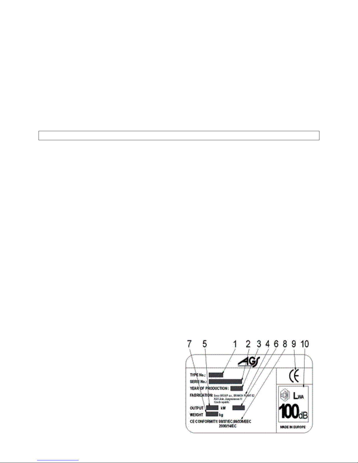
2.3 OZNAČENÍ
Každý samojízdný žací stroj je označen výrobním štítkem umístěným pod sedadlem.
Obsahuje tyto údaje:
1. Typ stroje
2. Sériové číslo
3. Rok výroby
4. Název a adresa výrobce
5. Výkon motoru
6. Otáčky motoru
7. Hmotnost
8. Předpisy EC, s nimiž je posouzena shoda výrobku
9 Značka shody výrobku
10. Garantovaná hladina hluku dle směrnice 2000/14/EC
Sériové číslo Vám zapíše prodejce při předání stroje na druhou stranu obalu tohoto návodu.
3. TECHNICKÉ PARAMETRY
Page 9

7
Motor
Objem (cm3)
Otáčky (min-1)
Počet válců
Palivo
Objem nádrže (l)
Rozměry stroje: délka x šířka x výška (mm)
Rychlost max. vpřed / vzad (km/hod)
Akumulátor
Kola zadní / tlak v pneumatikách
Kola přední / tlak v pneumatikách
Převodová skříň
Záběr (cm)
Výška sečení (cm)
Spojka žacího ústrojí
Zvedání žacího ústrojí
Časově průměrovaná emisní hladina
akustickéhotlaku A na pracovním místě obsluhy
LpAeq (dB) dle ČSN EN ISO 11201 a ČSN EN
836+A1/A2
Souhrnná hodnota zrychlení celkových vibrací a
v
(min.s-2)dle ČSN EN 836+A1/A2
Souhrnná hodnota zrychlení vibrací přenášených
na ruku-paži obsluhy ahv (min.s-2)dle ČSN EN
836+A1/A2
Briggs
& Stratton 17,5HP INTEK
502
2 700
1
benzín Natural 95
10
2230 x 1070 x 1110
8 / 4
12V 24Ah
15x6,00-6 / 80 - 140 kPa
18x10-8 / 80 - 140 kPa
Tuff-Torq K46, hydrostatická
105
3 - 8
elektromagnetická
elektricky ovládaný šroub
84
0,94
< 2,5
Page 10
8
4 . VYBALENÍ
Samojízdný žací stroj je dodáván v latěném obalu. Z přepravních důvodů jsou některé skupiny stroje ve výrobním závodě
demontovány a namontují se až před uvedením do provozu. Vybalení stroje a přípravu k provozu provádí prodejce v rámci
předprodejního servisu.
4.1 KONTROLA PO VYBALENÍ
Po odstranění obalu sundejte opatrně stroj s palety – použijte nájezdy, jinak hrozí nebezpečí jeho poškození. Zkontrolujte stroj,
zda nebyl během přepravy poškozen. Vybalte také všechny nenamontované skupiny a zkontrolujte je.
V základním balení jsou dodány:
• žací stroj
• volant
• sedadlo
• dokumentace (balící list, Návod k obsluze žacího stroje, Návod k obsluze motoru, Návod k akumulátoru, Servisní knížka)
4.1.1 LIKVIDACE OBALU
Po vybalení stroje je nutno provést likvidaci obalu. Likvidaci provádějte dle příslušného zákona. Rozdělení obalu podle jeho
materiálu provádějte dle příslušného katalogu obalů. Tuto operaci lze svěřit specializované fi rmě.
4.2 PŘÍPRAVA PRO UVEDENÍ DO PROVOZU
Vzhledem k technickému charakteru této činnosti provádí přípravu žacího stroje do provozu Váš prodejce (dle pokynů
výrobce).
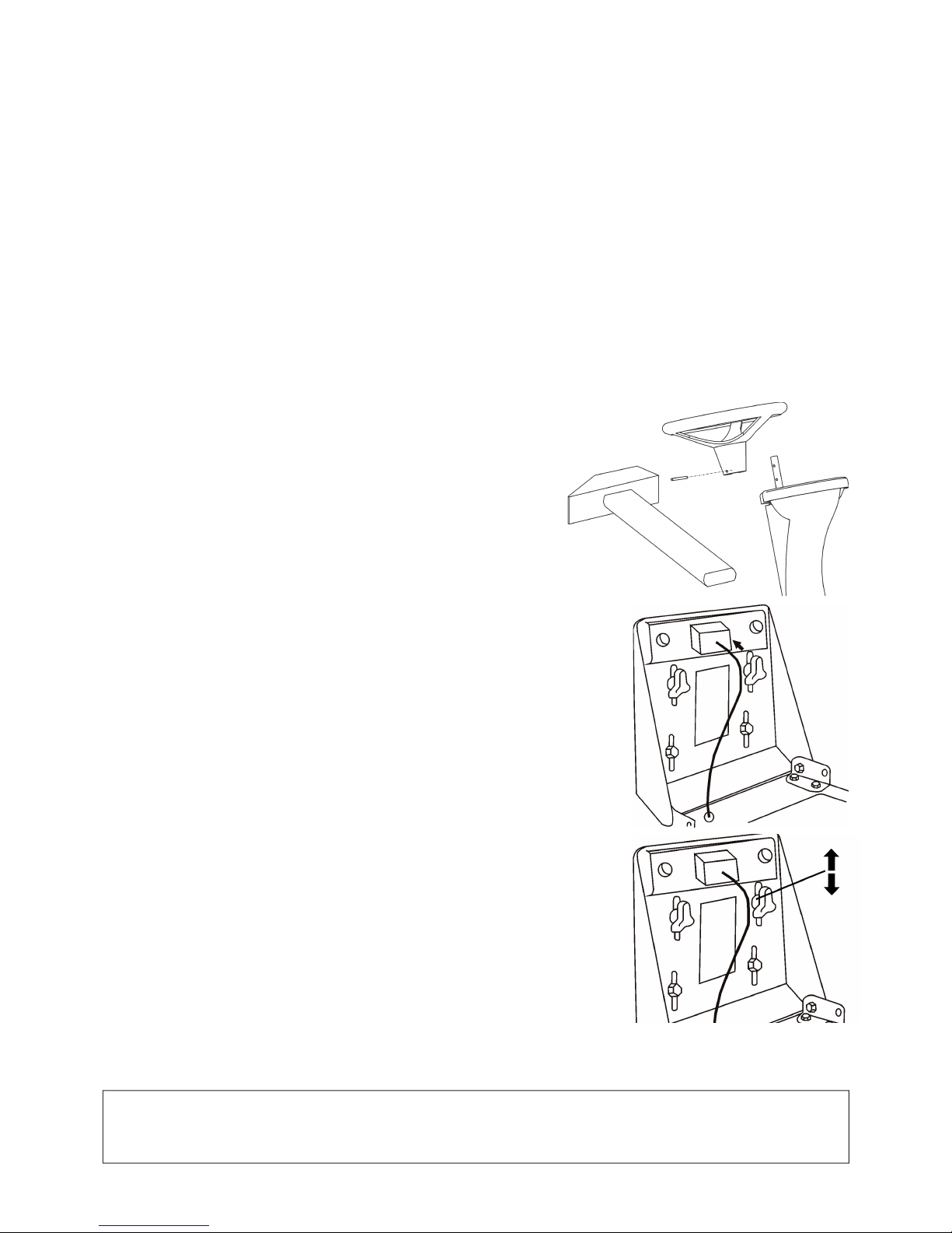
4.2.1 MONTÁŽ VOLANTU
Umístěte žací stroj na rovnou plochu a srovnejte zadní kola do přímého směru.
Nasaďte volant a zajistěte jej ve zvolené výškové poloze dodaným kolíkem v
odpovídajícím otvoru.
4.2.2 MONTÁŽ SEDADLA
Sundejte krycí obal sedadla. Přiložte sedadlo na jeho místo ve stroji a připevněte jej
pomocí šroubů tak, jak jsou v sedadle předmontovány.
4.2.3 NASTAVENÍ POLOHY SEDADLA
Nastavení polohy sedadla proveďte následujícím postupem:
Uvolněte šrouby s plastovými růžicemi. Posuňte sedadlo vpřed nebo vzad do požadované
polohy. Dotáhněte opět pevně šrouby s plastovými růžicemi .
4.2.4 PŘIPOJENÍ AKUMULÁTORU
Při uvádění akumulátoru do provozu postupujte dle pokynů uvedených v Návodu k akumulátoru. Akumulátor je umístěn na
pravé straně vedle sloupku sedadla pod kapotou motoru.Uvolněte šrouby na pólových vývodech akumulátoru. Červený vodič
přiložte na “+” pól akumulátoru a zajistěte šroubem. Hnědý vodič připojte na “–” pól akumulátoru a zajistěte šroubem.
UPOZORNĚNÍ
Opačné připojení vodičů, než je výše uvedeno, má za následek poškození stroje.
Při odpojování akumulátoru vždy jako první odpojte “–” pól akumulátoru.
Dodržujte pokyny pro údržbu uvedené v Návodu k akumulátoru.
Page 11
9
5. UVEDENÍ DO PROVOZU
Vzhledem k technickému charakteru této činnosti provádí uvedení žacího stroje do provozu Váš prodejce (dle pokynů výrobce).
5.1 KONTROLA HLADINY OLEJE V MOTORU
Postupujte dle Návodu k obsluze motoru, dbejte pokynů uvedených v kapitole 7.1 “Přehled kontroly a údržby“.
5.2 KONTROLA AKUMULÁTORU
Provádějte dle Návodu k akumulátoru.
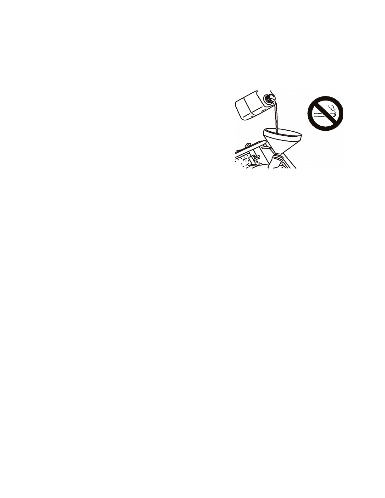
5.3 NAPLNĚNÍ NÁDRŽE BENZÍNEM
• Stroj je z bezpečnostních důvodů transportován bez paliva.
• Plnění nádrže provádějte pouze při zastaveném a studeném motoru.
• Používejte jen benzín s oktanovým číslem 95 (Natural 95).
• Nádrž je umístěna ve sloupku sedadla a je snadno přístupná po odklopení
sedadla směrem dopředu.
• Uzávěr nádrže otvírejte pomalu, protože v nádrži může být přetlak
benzínových výparů.
• Při doplňování nádrže používejte kanystr s nálevkou, nádrž nepřeplňujte.
• Výšku hladiny benzínu v nádrži lze sledovat pohledem ve výřezu v levé části
sloupku sedadla.
• Otřete okolí uzávěru nádrže i uzávěr vždy do sucha. Čistěte i celou nádrž
pravidelně, protože případné nečistoty v benzínu mohou způsobit poruchu.
• Při manipulaci s palivem nejezte, nekuřte a nepoužívejte otevřený oheň.
Page 12
10
6 . OVLÁDÁNÍ STROJE
6.1 POPIS A FUNKCE OVLADAČŮ
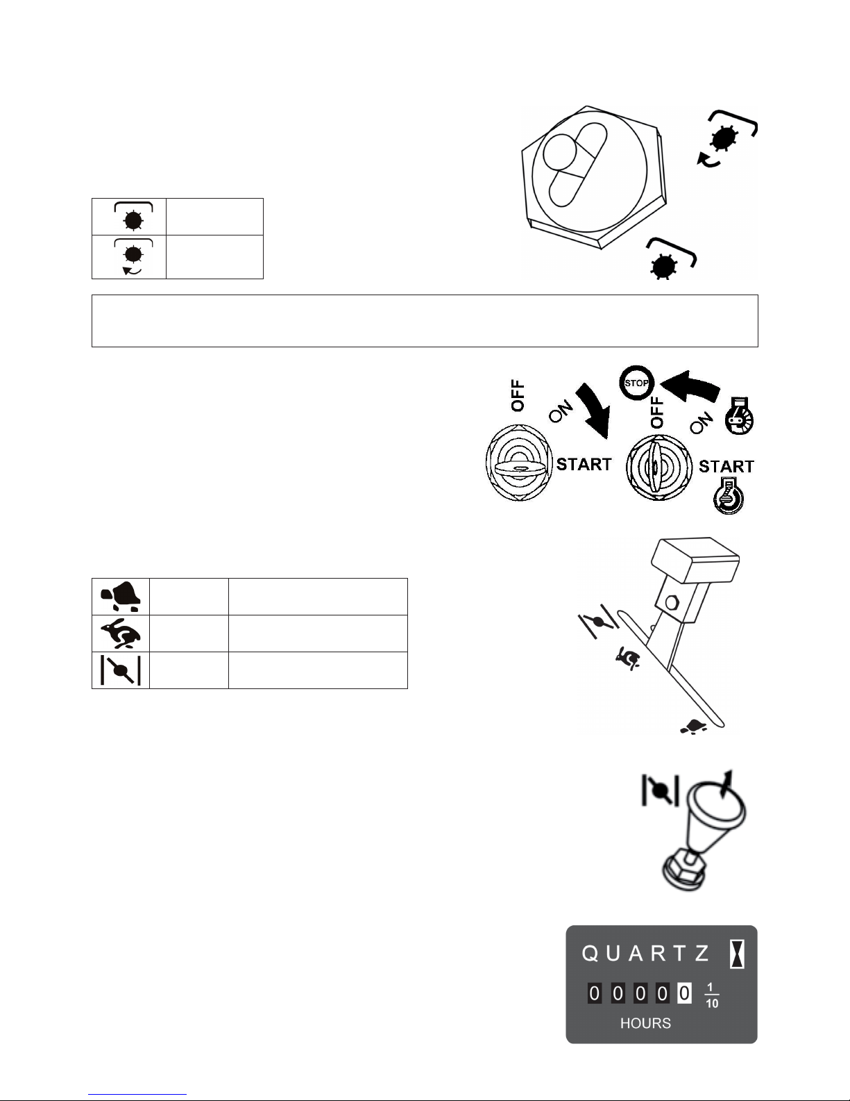
6.1.1 SPÍNAČ ŽACÍHO ÚSTROJÍ
Spínač žacího ústrojí zapíná elektromagnetickou spojku, jejíž řemenice přenáší
přes klínový řemen pohon od motoru na řemenici žacího ústrojí. Spínač je jištěn
v poloze “vypnuto” proti nežádoucímu zapnutí. Pro zapnutí je nezbytné páčku
spínače povytáhnout a překlopit do polohy “zapnuto”.
VYPNUTO
ZAPNUTO
UPOZORNĚNÍ:
Jestliže je žací ústrojí zvednuto do transportní polohy (viz kap. 6.1.6), nelze pohon žacího ústrojí spustit.
Transportní poloha je hlídána bezpečnostním spínačem.
6.1.2 SPÍNACÍ SKŘÍŇKA
Klíček má 3 polohy:
OFF - zapalování vypnuto
ON - zapalování zapnuto
START - spuštění motoru
6.1.3 PÁČKA PLYNU
Reguluje otáčky motoru, její jednotlivé polohy jsou:
(obrázek ze 6.1.3)
MIN volnoběžné otáčky motoru
MAX maximální otáčky motoru
SYTIČ * start motoru za studena
* Sytič je na stroji instalován v závislosti na typu motoru.
6.1.4 SYTIČ
Umožňuje start motoru za studena. Je na stroji instalován
v závislosti na typu motoru.
6.1.5 POČÍTADLO MOTOHODIN
Počítadlo motohodin je namontováno v závislosti na typu stroje. Je v činnosti jen při
zapnutém zapalování a sepnutém sedadlovém spínači (automaticky vahou obsluhy).
Manipulace s počítadlem znamená ztrátu záruky. Při poruše počítadla motohodin ihned
informujte Váš servis.
Page 13
11
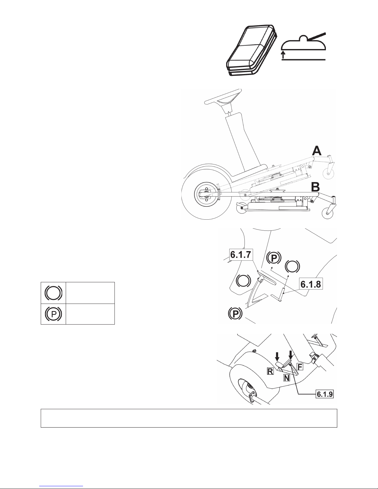
6.1.6 SPÍNAČ ZVEDÁNÍ ŽACÍHO ÚSTROJÍ
Tento spínač slouží ke zvedání žacího ústrojí do transportní polohy
a ke spouštění do pracovní polohy nastavené pákou 6.1.11.
Polohy žacího ústrojí jsou: A - transportní poloha
B - pracovní poloha
Pro zvedání nebo spouštění spínač stiskněte a držte jej
stisknutý.
Po dosažení koncové polohy žacího ústrojí spínač ihned
uvolněte.
I když jsou koncové polohy jištěny bezpečnostní spojkou,
v případě delšího držení spínače ve stisknutém stavu hrozí
porucha elektrické instalace.
6.1.7 BRZDA
Když je pedál brzdy plně sešlápnut, je žací stroj zabrzděn. Nikdy
nepoužívejte brzdu současně s funkcí pojezdu - hrozí nebezpečí
poškození převodovky.
6.1.8 PÁKA PARKOVACÍ BRZDY
Páka parkovací brzdy má 2 polohy. Před nastavením páky do polohy “P”
sešlápněte pedál brzdy Odbrzdění parkovací brzdy se provede sešlápnutím
pedálu brzdy, při tom se aretace zajištění páky automaticky uvolní.
ODBRZDĚNO
ZABRZDĚNO
6.1.9 PEDÁL POJEZDU
Ovládá náhon kol a reguluje rychlost stroje v obou směrech.
Pohon vpřed:
Pomalu sešlápňete pedál špičkou nohy ve směru “F“, většímu sešlápnutí
odpovídá vyšší rychlost a naopak.
Pohon vzad:
Pomalu sešlápněte pedál patou nohy ve směru “R“, většímu sešlápnutí
odpovídá vyšší rychlost a naopak.
Jakmile pedál uvolníte, vrátí se automaticky do polohy “N“ (neutrál)
a stroj se zastaví.
UPOZORNĚNÍ !!!
Změna směru jízdy je možná až po zastavení stroje.
Page 14
12
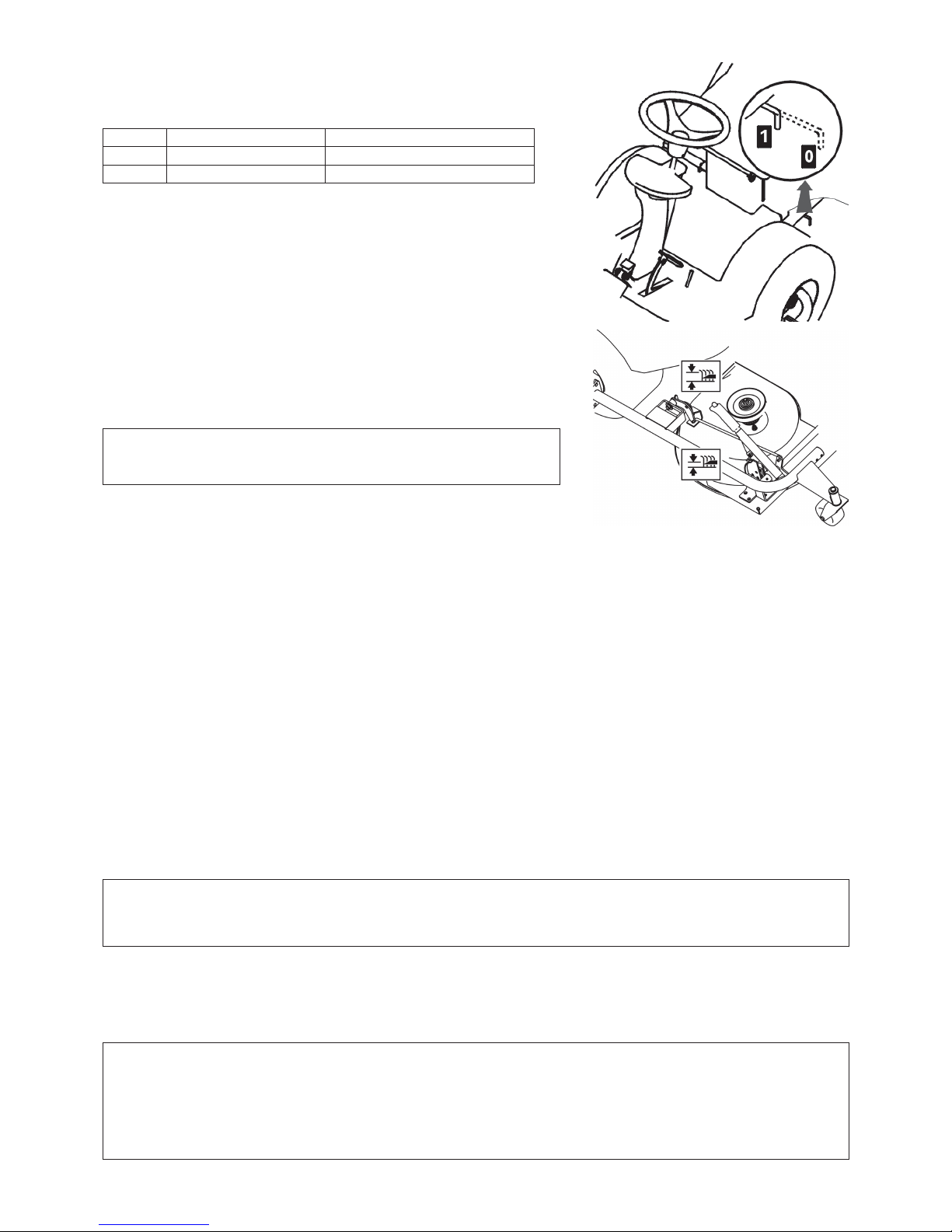
6.1.10 PÁKA BY-PASSU
Páka by-passu slouží k vyřazení převodu pro pohon předních kol.
Má 2 polohy:
Poloha Pohon předních kol Použití
0 vypnut tlačení stroje, motor v klidu
1 zapnut jízda, motor v chodu
6.1.11 PÁKA NASTAVENÍ VÝŠKY ŽACÍHO ÚSTROJÍ
Slouží k nastavení výšky žacího ústrojí od země. Má 8 pracovních poloh, které
odpovídají výšce sečení 3 až 8 cm. Čím vyšší je číslo polohy páky, tím vyšší
porost po sečení zůstává.
UPOZORNĚNÍ !!!
Při pojezdu stroje bez sečení musí být žací ústrojí zvednuto
spínačem 6.1.6 do transportní polohy.
6.2 PROVOZ A OBSLUHA
Bezpečnostní ochrana stroje
Žací stroj je vybaven bezpečnostními kontakty, které se spínají spínačem umístěným pod sedadlem. Motor se automaticky
zastaví, opustí-li řidič sedadlo. Motor může být nastartován jen tehdy, je-li spínač žacího ústrojí v poloze “vypnuto”, žací ústrojí
je zvednuto do transportní polohy a není sešlápnutý pedál pojezdu.
6.2.1 NASTARTOVÁNÍ MOTORU
• Zkontrolujte množství benzinu v nádrži.
• Posaďte se pohodlně na sedadlo stroje a žací ústrojí zvedněte spínačem 6.1.6 do transportní polohy.
• Spínač zapínání žacího ústrojí 6.1.1 dejte do polohy „VYPNUTO“.
• Pozor, nešlapejte na pedál pojezdu 6.1.9.
• Páčku plynu 6.1.3 nastavte do polohy „MAX“.
• Vytáhněte sytič 6.1.4.
• Nemanipulujte s pákou nastavení výšky žacího ústrojí 6.1.11.
• Otočte klíčkem zapalování 6.1.2 do polohy „START“. Doba startování nesmí překročit 10 sekund – hrozí poškození
bateriového spínače.
• Motor „běží“ - pusťte klíček zapalování. Klíček se automaticky vrátí do polohy “ON”.
• Postupně zasuňte sytič 6.1.4.
• Páčku ovládání plynu 6.1.3 pomalu nastavte do polohy „MIN“ (snižte otáčky motoru).
• Motor nechte běžet pár minut před zapnutím žacího ústrojí.
NEBEZPEČÍ !
Nikdy nenechávejte nastartovaný motor v uzavřeném nebo ve špatně větraném prostoru.
Výfukové plyny, obsahující oxid uhelnatý, jsou velmi nebezpečné. Ruce, nohy, volný oděv držte z dosahu
pohyblivých součástí a výfuku.
6.2.2 ZASTAVENÍ MOTORU
• Páčku ovládání plynu 6.1.3 dejte do polohy „MIN“.
• Vypněte žací ústrojí spínačem 6.1.1 (viz kapitola 6.2.4).
• Je-li motor přehřátý, nechte jej chvíli běžet při minimálních otáčkách.
• Vypněte motor otočením klíčku 6.1.2 do polohy „STOP“ a vyjměte klíček ze zapalování.
UPOZORNĚNÍ !!!
Nikdy nezastavujte motor pouhým sesednutím ze sedadla, ponechání klíčku v zapalování v poloze „ON“ může způsobit
závadu na elektroinstalaci. Vždy otočte klíček do polohy „OFF“ a vyjměte jej ze spínací skříňky.
DŮLEŽITÉ !!
Před vypnutím zapalování snižte otáčky na pomalý chod pro případ samozápalu, nedodržení může mít za následek
poškození motoru a výfuku.
Page 15

13
6.2.3 ZAPNUTÍ A VYPNUTÍ ŽACÍHO ÚSTROJÍ
a) Zapnutí
• Nastavte páčku plynu 6.1.3 do polohy “MAX“.
• Spusťte spínačem 6.1.6 žací ústrojí do pracovní polohy, nastavené pákou 6.1.11, jinak hrozí poškození klínového řemene.
• Nastavte spínač žacího ústrojí 6.1.1 do polohy „ZAPNUTO“.
Žací ústrojí se zapne jen tehdy, sedí-li obsluha na sedadle stroje
b) Vypnutí
• Nastavte spínač žacího ústrojí 6.1.1 do polohy “VYPNUTO“.
• Opustí-li řidič sedadlo, zastaví se automaticky motor a tím také žací ústrojí.
UPOZORNĚNÍ !!!
Nikdy nevypínejte žací ústrojí jen sesednutím ze sedadla. Pokud nepřepnete klíček zapalování z polohy “ON”
do polohy “OFF” (STOP), je část elektroinstalace stále pod napětím a může dojít k její závadě.
6.2.4 NASTAVENÍ VÝŠKY ŽACÍHO ÚSTROJÍ
Žací ústrojí musí být spuštěno do pracovní polohy „B“ (viz obrázek v kap. 6.1.6) přepnutím spínače 6.1.6 do polohy
„spouštění“.
Páku zvedání žacího ústrojí 6.1.11 posuňte směrem nahoru, chcete-li nastavit žací ústrojí výš od země, nebo ji posuňte směrem
dolů, chcete-li nastavit žací ústrojí blíže k zemi.
Poloha „1“ se používá pro kopírování nerovností terénu. Neužívejte tuto výšku nastavení trvale, protože by mohlo dojít ke
zvýšenému opotřebení dílů žacího ústrojí.
Žací ústrojí je vybaveno 3 pojezdovými kolečky, které v případě nerovností terénu zvedají rám se žacím ústrojím a slouží tak jako
ochrana žacích nožů před poškozením.
6.3 POJEZD
Před zahájením pojezdu se přesvědčete sešlápnutím pedálu provozní brzdy 6.1.7, že parkovací brzda je odbrzděna. Páka parkovací
brzdy 6.1.8 nesmí zůstat v poloze „P“!
Páka by-passu 6.1.10 musí být nastavena do polohy “1”, tj. by-pass pojezdu musí být zapnut.
Při přejíždění na místo, kde bude prováděno sečení, musí být žací ústrojí vypnuto (spínač 6.1.1) a zvednuto do transportní polohy
přepnutím spínače 6.1.6 do polohy „zvedání“.
Při přejíždění překážek s výškou nad 8 cm (obrubníky apod.) je nutné používat nájezdy, aby nedošlo k poškození žacího ústrojí
a převodové skříně.
Vlastní pojezd proveďte následujícím postupem:
• Snižte otáčky motoru tak, že páčku plynu 6.1.3 přesunete do polohy „MIN“.
• Při rozjíždění pomalu sešlapujte pedál pojezdu 6.1.9 dle požadovaného směru jízdy - při rychlém sešlápnutí pedálu hrozí
nebezpečí úrazu.
• Změna směru pojezdu vpřed-vzad je možná pouze po zastavení stroje. Pokud není stroj zastaven, hrozí porucha
převodovky.
• Nikdy nepoužívejte pedál pojezdu a pedál brzdy současně - jinak hrozí porucha převodovky.
UPOZORNĚNÍ !!!
Zastavení stroje je možné pouze pozvolným uvolněním nohy z pedálu pojezdu a poté sešlápnutím pedálu brzdy. Při
sešlápnutí pedálu brzdy se pedál pojezdu přesouvá automaticky do neutrální polohy. Brzdná dráha je přitom kratší než 2 m.
6.4 RYCHLOST POJEZDU A SEČENÍ TRÁVY
Nastavte páčku plynu 6.1.3 do polohy „MAX“. Nastavte výšku žacího ústrojí pákou 6.1.11 (viz kapitola 6.2.4).
Obecně platí, že čím vlhčí, vyšší a hustší je tráva, tím nižší rychlost pojezdu by měla být použita. Je-li rychlost stroje příliš velká,
nebo při velkém zatížení, klesají otáčky nožů a zhoršuje se kvalita sečení.
Jestliže je tráva velmi vysoká, mělo by se sekat vícekrát. První řez v maximální výšce, případně se zmenšením šířky záběru a
další řez již v požadované výšce.
Doporučujeme sekání v podélném či křížovém směru. Překrývání předešlého záběru stroje umožní zvýšení účinku nožů a zlepší
i vzhled posečeného pozemku.
Při jízdě na nerovném povrchu může docházet ke kolísání pojezdové rychlosti.
Dle podmínek doporučujeme tyto rychlosti:
Stav porostu Doporučená rychlost
vysoký, hustý a mokrý 2 km/hod
průměrné podmínky 3 – 5 km/hod
nízký, suchý porost < 5 km/hod
přejíždění bez zapnutého žacího ústrojí < 7 km/hod
6.5 JÍZDA NA SVAHU
Tento žací stroj může pracovat na svazích do sklonu až 14° (25%). Při práci ve svahu používejte vždy nižšší rychlost pojezdu.
Jezděte pouze kolmo na vrstevnice, tj. nahoru a dolů. Jízda ve směru vrstevnice není dovolena. Ze svahu a přes překážky
jezděte pomaleji. Zvláštní opatrnost si vyžaduje zatáčení a otáčení se ve svahu. Při zastavení stroje ve svahu používejte vždy
parkovací brzdu. Při přetěžování stroje na svazích nad 14° (25%) může dojít k vážnému poškození převodové skříně. Za takto
vzniklou závadu nenese výrobce žádnou zodpovědnost.
Page 16

14
7 . ÚDRŽBA STROJE
7.1 PŘEHLED KONTROLY A ÚDRŽBY
Po sezoně - před odstavením stroje
Před sezonou
Každých 100 hodin
Každých 50 hodin
Každých 25 hodin
Měsíčně
Pravidelně po každém použití
Po prvních 5 hodinách
Po prvních 2 hodinách
Před každým použitím
Kontrola hladiny oleje (převodovka, motor)
O
O
Výměna oleje v motoru
O O 1,2 O
Výměna palivového fi ltru
O
Údržba akumulátoru (kontrola hladiny elektrolytu, čistění)
OO
Seřízení a kontrola řemenů
O O 4O O
Kontrola ovládání brzdy
OO
Kontrola tlaku pneumatik
OO
Kontrola připevnění kabelů (uvolněné rychloupínací části)
OO
Čištění žacího stroje
OO
Kontrola šroubových spojů
OOO
Kontrola funkce bezpečnostních spínačů a prvků
O
Kontrola a seřízení chodu motoru, převodovky, elektromagnetické spojky
O
Kontrola a údržba vzduchového fi ltru, zapalovací svíčky, případně výměna
O 1,2
Kontrola stavu žacího ústrojí (vůle, souosost hřídelů, kontrola a ostření nožů)
O O 3
Vysvětlivky k tabulce:
1. Výměnu oleje provádějte častěji, pokud je žací stroj více zatěžován nebo pracuje při venkovních teplotách okolo 35°C nebo
vyšších.
2. V případě práce stroje v prašném prostředí provádějte kontrolu častěji.
3. Kontrolu provádějte častěji, pokud stroj pracuje v písčitém prostředí.
4. Kontrolu provádějte častěji, je-li nasazen nový řemen.
7.2 KONTROLA TLAKU PNEUMATIK
Dodržujte předepsaný tlak v pneumatikách a pravidelně jej kontrolujte. Jiné hodnoty tlaku mohou vést ke ztížené jízdě, případně
až ke ztrátě kontroly nad strojem. Dodržení předepsaného tlaku je rovněž důležité pro rovnoměrné sečení.
• Tlak v předních pneumatikách 80 - 140 kPa
• Tlak v zadních pneumatikách 80 - 140 kPa
7.3 ÚDRŽBA PO PRÁCI
Po ukončení sečení zvedněte žací ústrojí do nejvyšší polohy a vypněte pohon nožů. Vypněte zapalování, sešlápněte pedál brzdy
a zajistěte polohu stroje parkovací brzdou.
7.3.1 ČISTĚNÍ
Po skončení každého sečení odstraňte všechny nečistoty a zbytky trávy z povrchu stroje a z rámu žacího ústrojí.
UPOZORNĚNÍ !!!
Před začátkem čistění, mytí nebo opravování stroje vytáhněte klíčky ze zapalování. Vždy pracujte v pevné obuvi,
rukavicích a oděvu určeném pro práci. Vyvarujte se rozlití paliva, oleje nebo jiných škodlivých látek.
7.3.2 MYTÍ
Vyvarujte se mytí vodou v blízkosti elektrických příslušenství na přístrojové desce, akumulátoru apod. Nepoužívejte vysokotlaké
mycí zařízení.
Mytí provádějte následovně:
• Mytí žacího stroje provádějte na rovné ploše.
• Očistěte pomocí houby plastové díly stroje mýdlovou vodou.
• Demontujte čepy 2 a čep 3 (viz obrázek v kap. 7.13).
• Zvedněte žací ústrojí za rám do svislé polohy. Pomocí škrabky a proudu vody odstraňte zbytky trávy z žacího ústrojí.
Page 17
15
7.4 ÚDRŽBA AKUMULÁTORU
Údržbu akumulátoru provádějte podle pokynů uvedených v Návodu k akumulátoru.
7.5 ÚDRŽBA MOTORU
Údržbu motoru provádějte podle pokynů uvedených v Návodu k obsluze motoru.
7.5.1 KONTROLA HLADINY OLEJE V MOTORU
Kontrolu hladiny oleje provádějte podle pokynů uvedených v Návodu k obsluze motoru.
7.5.2 VÝMĚNA OLEJE
Motor je vybaven vypouštěcím šroubem oleje.
• Vložte pod motor plochou nádobu o objemu alespoň 2 litrů a podložte stroj na opačné
straně, než je vypouštěcí šroub, aby z motoru vytekl všechen olej.
• Demontujte vypouštěcí šroub a vyšroubujte uzávěr plnění oleje, aby olej z motoru lépe a
rychleji vytékal.
• Našroubujte zpět vypouštěcí šroub, naplňte motor správným množstvím předepsaného
oleje (viz Návod k obsluze motoru) a uzavřete uzávěr plnění oleje.
• Vypuštěný olej dopravte na místo likvidace starých olejů.
7.5.3 VÝMĚNA PALIVOVÉHO FILTRU
Výměnu palivového fi ltru provádějte podle pokynů uvedených
v Návodu k obsluze motoru.
7.5.4 ÚDRŽBA VZDUCHOVÉHO FILTRU
Údržbu provádějte podle pokynů uvedených v Návodu k obsluze motoru.
7.5.5 ÚDRŽBA ZAPALOVACÍ SVÍČKY
Údržbu provádějte podle pokynů uvedených v Návodu k obsluze motoru.
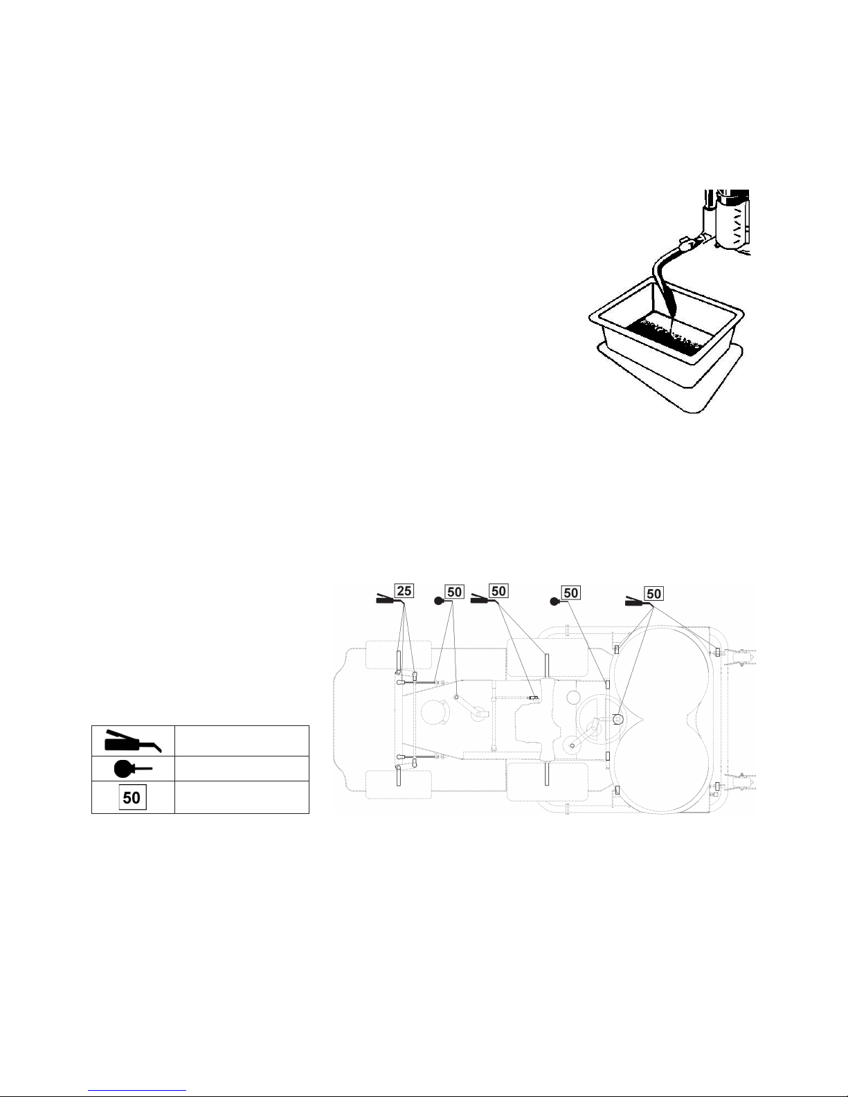
7.6 MAZÁNÍ
Mazání provádějte dle mazacího plánu,
kontrolu funkcí včetně údržby dle přehledu
v kap. 7.1.
Ložiska napínacích kladek, vodících kladek
a ložiska žacího ústrojí jsou samomazná.
Před odstavením stroje na delší dobu
promažte důkladně všechna místa, která
mazání vyžadují.
plastické mazivo
olej SAE 30
interval v hodinách
Plastickým mazivem se mažou:
• čepy natáčení kol
• úhlové klouby spojovacího táhla pojezdu - demontovat, namazat
• úhlové klouby čepů kol - demontovat, namazat
• šroub táhla brzdy - promazat táhlo v blízkosti otvoru šroubu
• šroub táhla zvedání žacího ústrojí - promazat táhlo v blízkosti otvoru šroubu
• úhlové klouby spojovacího táhla řízení - demontovat, namazat
• ložiska zadních kol
• čepy kol procházející nápravou
• středový otočný čep zadní nápravy - přes mazničku
• ložiska hřídele volantu - promazat
• napínací řemenice - demontovat a namazat čepy
Olejem je třeba namazat:
• lanko řízení
• čepy zajištění žacího ústrojí
• otočné body pedálu pojezdu
• otočné body pedálu brzdy
Page 18
16
7.7 VÝMĚNA POJISTKY
Zvedněte přední kapotu. Rozšroubujte pouzdro, vyjměte pojistku a vložte novou pojistku o stejné hodnotě,
jakou měla původní pojistka, tj. 20 A.
Jestliže i po výměně pojistky nejde nastartovat motor, kontaktujte autorizovaný servis.
7.8 NADZVEDNUTÍ STROJE
Chcete-li žací stroj nadzvednout, použijte zvedáku a podpěr.
Při zvedání postupujte následovně:
• Umístěte zvedák pod převodovku a zvedněte přední část stroje.
• Vložte dvě podpěry pod konce náprav uvnitř strany zadních kol.
• Zvedněte přední část stroje a vložte dvě podpěry pod konce obou čepů předních kol.
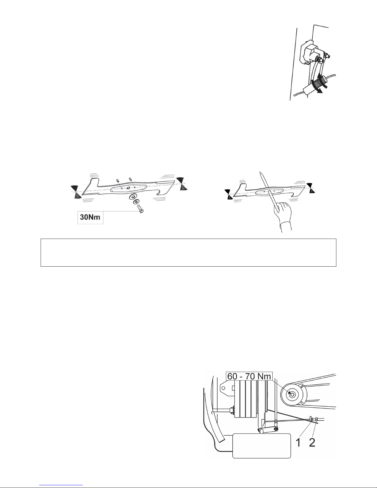
7.9 VÝMĚNA NOŽŮ ŽACÍHO ÚSTROJÍ
Žací nože musí být ostré, staticky vyvážené a rovné. Tyto podmínky jsou důležité pro rovnoměrnou výšku vlastního sečení
a kvalitu řezu. Otupené ostří zhoršuje jak kvalitu sečení, tak i výsledek sbírání posečené trávy.
UPOZORNĚNÍ !!!
Jakmile dojde k nárazu nožů do nějaké pevné překážky, ihned zastavte motor a nože zkontrolujte! Může dojít
k poškození nebo přestřižení střižných kolíků. Nahraďte přestřižené kolíky novými, které jsou ve výbavě stroje.
Zkontrolujte také, zda jsou připevňovací šrouby nožů dotaženy na předepsaný moment.
Výměnu nožů provádějte následujícím způsobem:
• Zvedněte žací ústrojí do transportní polohy.
• Odšroubujte oba nože, očistěte je a proveďte naostření. Zkontrolujte statickou vyváženost nožů (viz obrázek výše).
• Při montáži dbejte na to, aby vyhnutí lopatek směřovalo nahoru dovnitř pláště žacího ústrojí. Nezaměňte levý nůž za pravý.
U pravého nože je šroub s levým závitem.
• Kontrolujte stav střižných kolíků, které slouží jako ochrana žacího ústrojí proti poškození. Jsou-li střižné kolíky poškozené,
ihned je vyměňte.
• Připevňovací šrouby nožů dotáhněte pečlivě předepsaným utahovacím momentem 30±3 Nm.
7.9.1 OSTŘENÍ NOŽŮ
Nůž může být ostřen pilníkem nebo bruskou. Neprovádějte ostření přímo na žacím ústrojí.
Velkou péči věnujte vyrovnání a vyvážení nožů. Nevyrovnané a nevyvážené nože mohou svými vibracemi způsobit poruchu
motoru nebo žacího ústrojí.
Při vyvažování zasuňte šroubovák do středící díry a ustavte nůž do vodorovné polohy (viz obrázek 7.9). Když nůž zůstane v této
poloze, je vyvážený. Jestliže jeden z konců nože převažuje, provádějte broušení této strany až do vyvážení
Přípustná statická nevyváženost může být 2g max.
7.10 ÚDRŽBA ŘÍZENÍ
Pravidelně kontrolujte vůli v řízení. V případě zjištění větší vůle ji
vymezte. Při vymezování vůle nejprve srovnejte kola do přímého
směru. Povolte matici 1 a otáčením seřizovacího šroubu 2 na konci
lanka vymezte vůli v řetězu na minimum. Pak matici 1 pevně
dotáhněte. Proveďte toto seřízení i na druhém konci řetězu. Dbejte
na to, aby lanka na obou koncích řetězu byla stejně napnuta.
Page 19
17
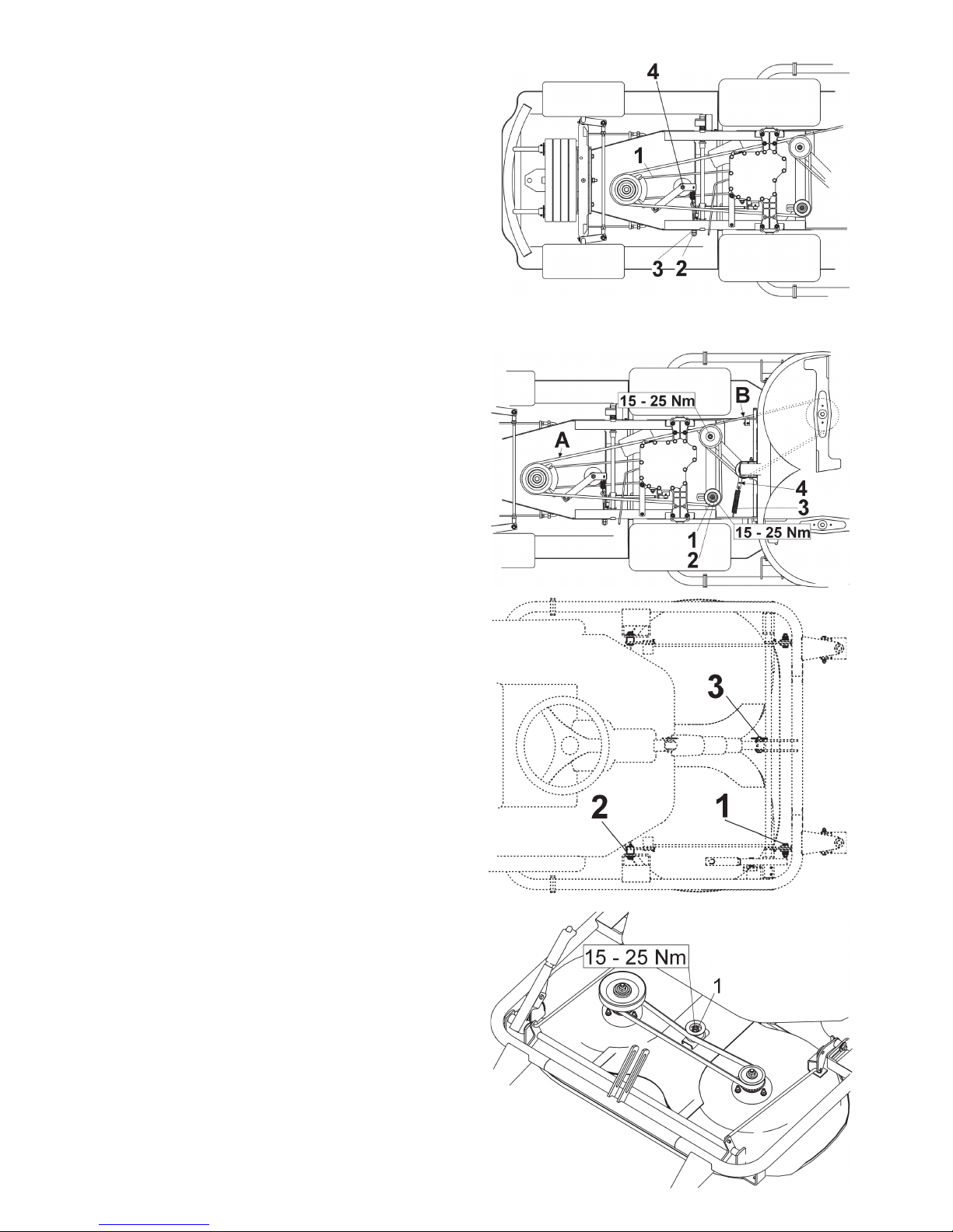
7.11 KONTROLA A SEŘÍZENÍ
ŘEMENU POHONU POJEZDU
Řemen 1 je správně napnutý, když při působení silou 4kp na řemen
v polovině vzdálenosti mezi řemenicemi dojde k prohnutí řemenu
přibližně o 1,5 cm. Seřízení napnutí řemenu proveďte otáčením
matice 3 na šroubu 2 napínajícím tažnou pružinu.
7.12
KONTROLA A SEŘÍZENÍ
KLÍNOVÝCH ŘEMENŮ POHONU ŽACÍHO ÚSTROJÍ
Klínový řemen A:
Řemen je správně napnutý, když při působení silou 4kp na řemen
v polovině vzdálenosti mezi řemenicemi dojde k prohnutí řemenu
přibližně o 1,5 cm. Seřízení napnutí řemenu proveďte posunutím
řemenice 2 po povolení matice 1. Po ukončení seřizování matici
1 dotáhněte.
Klínový řemen B:
Řemen pohonu žacího ústrojí je napínán pomocí kladky
s pružinou. Při uvolnění napnutí v důsledku namáhání řemenu
zvětšete napnutí přemístěním závěsného oka pružiny 3 do
druhého otvoru v rameni 4 napínací kladky.
7.13 VYJMUTÍ ŽACÍHO ÚSTROJÍ ZE
STROJE
• Spusťte žací ústrojí do pracovní polohy přepnutím spínače
6.1.6. Po dosažení polohy spínač ihned uvolněte.
• Zatažením za páku napínací řemenice 4 (obr. 7.12) uvolněte
klínový řemen a vyjměte jej.
• Vyvlékněte pružinu 3 (obr. 7.12) z ramene napínací kladky.
• Vyvlékněte pružné závlačky z předních čepů 2 a z obou
zadních čepů 1 zavěšení žacího ústrojí.
• Demontujte čep 3 a šroub zvedání žacího ústrojí.
• Vysuňte s pomocí kleští oba zadní čepy 1 zavěšení žacího ústrojí.
Při vysouvání dejte pozor, aby nedošlo ke zranění rukou
nebo prstů.
• Vysuňte přední čepy zavěšení 2.
• Vytáhněte pomalu žací ústrojí ze stroje.
7.14 SEŘÍZENÍ OZUBENÉHO
ŘEMENU POHONU NOŽŮ
• Spusťte žací ústrojí do pracovní polohy přepnutím spínače 6.1.6.
Po dosažení polohy spínač ihned uvolněte.
• Demontujte ochranný kryt ozubeného řemenu.
• Povolte matici 1 a napněte řemen posunutím napínací
řemenice.
• Kontrolujte napnutí. Řemen je správně napnut, když při
působení silou 4 kp v polovině vzdálenosti mezi řemenicemi
dojde k prohnutí řemene přibližně o 0,5 cm.
• Dotáhněte matici 1 a namontujte zpět ochranný kryt.
Page 20
18
7.15 VÝMĚNA ŘEMENŮ
Jde o poměrně náročnou operaci, svěřte ji autorizovanému servisu.
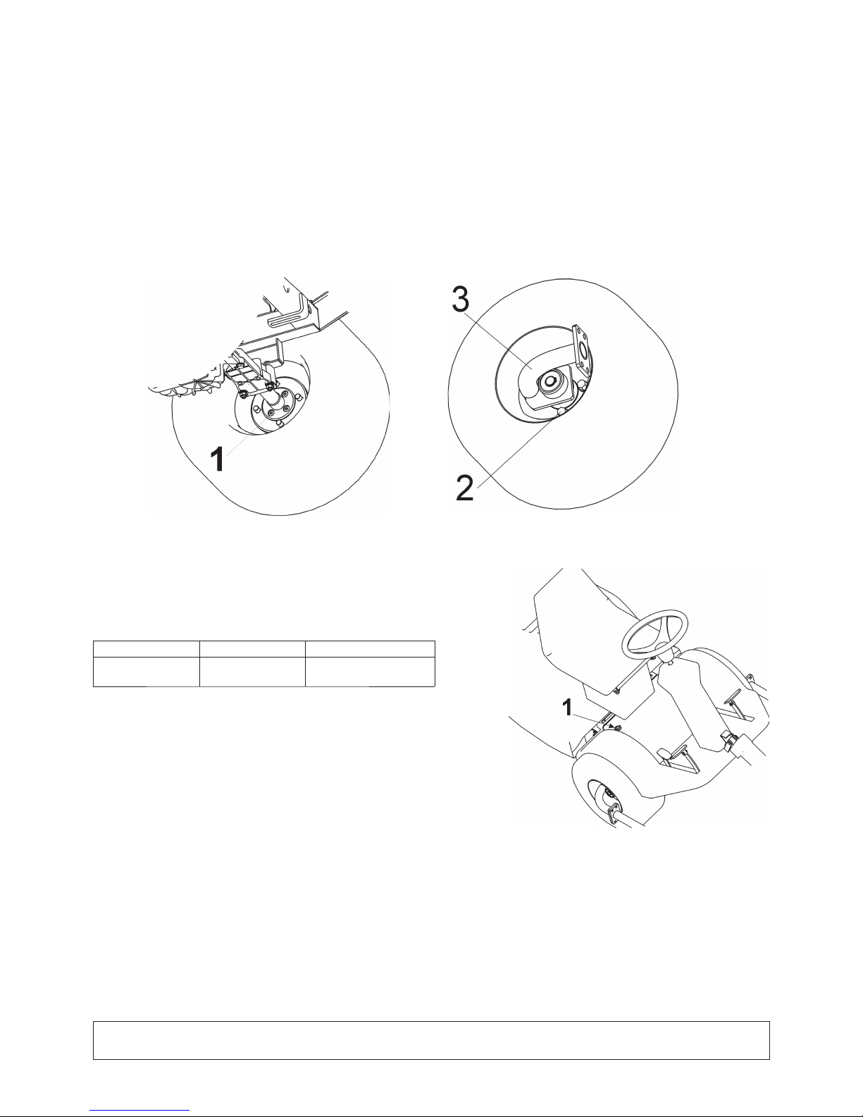
7.16 VÝMĚNA KOLA
• Před výměnou některého z kol zastavte motor a vyjměte klíček ze zapalování.
• Ustavte stroj na podpěry postupem uvedeným v kap. 7.8.
• Spusťte žací ústrojí do pracovní polohy přepnutím spínače 6.1.6. Po dosažení polohy spínač ihned uvolněte.
• Při výměně předního kola vyjměte žací ústrojí ze stroje (viz kap. 7.13) a odpojte přední rám žacího ústrojí.
• Zatažením za páku napínací řemenice 4 uvolněte klínový řemen B (obr. 7.12) a vyjměte jej.
• Na vnitřní straně kola vyšroubujte 4 šrouby 1, demontujte pojistný kroužek a vytáhněte držák předního rámu 3.
• Vyšroubujte 4 šrouby 2 a sundejte kolo.
• Při výměně zadního kola sejměte z kola ochranný kryt, demontujte pojistný kroužek, podložku a stáhněte kolo z hřídele.
Při zpětné montáži předního nebo zadního kola použijte opačný postup než při jeho demontáži.
Před nasazením kola očistěte všechny části a styčné části namažte lehce plastickým mazivem.
7.17 ÚDRŽBA HYDROSTATICKÉ PŘEVODOVKY
Pro spolehlivou funkci převodovek je nutné udržovat hladinu oleje ve správné
výši. Předepsané hodnoty jsou uvedeny
v tabulce níže. Plnící otvor 1 je dole v blízkosti sedadla (viz obrázek). Při
problémech s převodovkou vyhledejte okamžitě pomoc autorizovaného
servisu, hrozí nebezpečí vážného poškození.
Typ převodovky Specifi kace oleje Výška hladiny oleje
TUFF-TORQ K46 SAE 10W-30,
API CD
min. v polovině výšky
vyrovnávací nádrže
7.18 SEŘÍZENÍ BRZDY
Pokud začnou brzdy ztrácet účinnost, nechte provést jejich seřízení v autorizovaném servisu.
7.19 PŘEHLED UTAHOVACÍCH MOMENTŮ ŠROUBOVÝCH SPOJŮ
Žací ústrojí: Kapitola:
Středový šroub nože .............. 30 ± 3 Nm 7.9
Matice M12 kladky pohonu sečení .............. 45 - 55 Nm 7.14
Šroub M8x20 ramene napínací kladky řemenu pohonu žacího ústrojí ............. 25 - 35 Nm 7.14
Motor:
Šroub elektromagnetické spojky .............. 60 - 70 Nm 7.10
Šroub držáku napínací kladky řemenu pojezdu …........... 25 – 35 Nm 7.11 (poz.4)
UPOZORNĚNÍ!!!
Při demontáži a opětovné montáži samojistných matic je nutná jejich výměna za nové.
Page 21

19
8. ODSTRAŇOVÁNÍ PORUCH A ZÁVAD
Neprovádějte servisní operace, pokud nemáte odpovídající technické vybavení a kvalifi kaci. Níže uvedené operace mohou
být prováděny uživatelem stroje. Ostatní zde neuvedené servisní operace prováděné uživatelem ruší platnost záruky.
Výrobce neodpovídá za škody vzniklé v důsledku nekvalitního provedení nepovolených servisních operací uživatelem.
Porucha, závada Odstranění
Žací ústrojí seče
nerovnoměrně
Odstraňte nahromaděnou trávu ze spodní strany žacího ústrojí.
Přesvědčete se, zda jsou nože ostré a nedeformované.
Zkontrolujte dotažení nožů.
Zkontrolujte, zda nastavení výšky žacího ústrojí odpovídá údajům v kap. 6.1.11 a 6.2.4. Pokud ne,
proveďte nové nastavení.
Zkontrolujte napnutí hnacích řemenů dle kap. 7.12 a 7.14. V případě potřeby proveďte seřízení
napínání.
Zkontrolujte hřídele nožů. Při poškození nebo nadměrném opotřebení je vyměňte.
Zkontrolujte tělesa ložisek s ohledem na možná poškození. Podle zjištění proveďte opravu nebo je
vyměňte.
Mezi rotory nožů
zůstává neposečený
pruh
Při sečení husté trávy nebo trávy s nadměrně mokrým povrchem může zůstávat neposečený pruh.
Pojezdová rychlost by měla být zařazením vhodného převodového stupně přizpůsobena podmínkám
sečení. Motor by měl běžet při zcela otevřené klapce plynu.
Zkontrolujte, zda jsou nože ostré a nepoškozené. V případě potřeby nože vyměňte.
Zkontrolujte napnutí hnacích řemenů dle kap. 7.12 a 7.14. V případě potřeby proveďte seřízení
napínání.
Zkontrolujte tělesa ložisek s ohledem na možná poškození. Podle zjištění proveďte opravu nebo je
vyměňte.
Žací ústrojí trhá drny Zkontrolujte výšku sečení a případně ji upravte. K trhání drnů dochází častěji na nerovných
plochách.
Zkontrolujte tělesa ložisek s ohledem na možná poškození. Podle zjištění proveďte opravu nebo je
vyměňte.
Zkontrolujte, nejsou-li nože ohnuté. V případě potřeby nože vyměňte.
Řemen pohonu žacího
ústrojí se při provozu
zastavuje
Řemen pohonu žacího ústrojí může být poškozen, když během chodu stroje vyskočí z řemenice.
Pokud vyskočí i po přezkoušení dle následujících kroků, je třeba řemen vyměnit.
- Zkontrolujte napnutí řemenu dle kap. 7.12. V případě potřeby proveďte seřízení napínání.
- Zkontrolujte vedení řemenu.
- Zkontrolujte nastavení výšky sečení, v případě potřeby ji seříďte.
- Zjistěte, nebrání-li pohybu řemenu cizí těleso. Jestli ano, těleso odstraňte.
- Překontrolujte všechny řemenice. Vyhnuté nebo prasklé řemenice mohou způsobit problémy.
Podle potřeby je vyměňte.
- Zkontrolujte vnitřní plochu řemenice na motoru. Pokud je drsná nebo má trhlinky, je třeba
řemenici vyměnit.
- Zkontrolujte opotřebení dílů napínacího mechanismu, v případě potřeby opotřebené díly vyměňte.
Řemen pohonu žacího
ústrojí prokluzuje
Je-li tráva příliš vysoká nebo mokrá, může řemen sečení prokluzovat.
Zkontrolujte, zda není řemen opotřebován. Je-li tomu tak, vyměňte jej.
Zkontrolujte napnutí řemenu dle kap. 7.12 v návodě. V případě potřeby proveďte seřízení napínání.
Zkontrolujte napínací pružinu mechanismu napínáku řemene sečení. Vyta-ženou nebo poškozenou
pružinu vyměňte.
Řemen pohonu žacího
ústrojí se nadměrně
opotřebovává
Zkontrolujte všechna místa vedení řemenu.
Zjistěte, nebrání-li pohybu řemenu cizí těleso. Jestli ano, těleso odstraňte.
Zkontrolujte řemenice, jsou-li poškozené, vyměňte je.
Zkontrolujte nastavení výšky sečení, v případě potřeby ji seříďte.
Zkontrolujte napnutí řemenu dle kap. 7.12. V případě potřeby proveďte seřízení napínání.
Nože nelze uvést do
pohybu
Zkontrolujte, zda není řemen opotřebován nebo poškozen. Je-li tomu tak, vyměňte jej. Pokud je
volný, napněte jej.
Zkontrolujte pružinu napínacího mechanismu. Prasklou nebo poškozenou pružinu vyměňte.
Zjistěte, nebrání-li pohybu řemenu cizí těleso. Jestli ano, těleso odstraňte.
Nože se zastavují se
zpožděním
Zkontrolujte napnutí řemenu dle kap. 7.12. V případě potřeby proveďte seřízení napínání. Není-li už
další napnutí řemenu možné kvůli jeho značnému opotřebení, namontujte nový řemen.
Zjistěte, nebrání-li pohybu řemenu cizí těleso. Jestli ano, těleso odstraňte.
Zkontrolujte funkci elektromagnetické spojky, zda správně vypíná. V přípa- dě špatné funkce nechte
spojku vyměnit nebo opravit v autorizovaném servisu.
Page 22

20
Při zapnutí pohonu
žacího ústrojí vzniká
extrémní kmitání
řemenu
Zkontrolujte nože, nejsou-li nerovné nebo zkroucené, zkontrolujte také, jak jsou vyvážené.
V případě, že jsou zdeformované, vyměnte je.
Zkontrolujte, nemá-li řemen spálené plošky nebo nepravidelnosti, které mohou vést ke kmitání.
Poškozený řemen vyměňte.
Zkontrolujte, zda nejsou nože opotřebované nebo poškozené. V případě potřeby je vyměňte.
Zkontrolujte funkci elektromagnetické spojky, zda správně zapíná. V přípa- dě špatné funkce nechte
spojku vyměnit nebo opravit v autorizovaném servisu.
Zkontrolujte vnitřní plochu řemenice na motoru. Pokud je drsná nebo má trhlinky, je třeba řemenici
vyměnit.
Zkontrolujte, není-li na spodní straně žacího ústrojí nános trávy. Nános je nutné odstranit.
Zkontrolujte, zda není závada v uchycení motoru. Dle potřeby šrouby dotáhněte nebo je vyměňte.
Zkontrolujte napnutí řemenu dle kap. 7.12. V případě potřeby proveďte seřízení napínání.
Řemen pojezdu stroje
prokluzuje
Zkontrolujte napnutí řemenu pohonu pojezdu dle kap. 7.11. V případě potřeby proveďte seřízení
jeho napnutí.
Zkontrolujte, není-li řemen poškozen nebo opotřebován.
Zkontrolujte, neblokuje-li mechanismus spojky pojezdu cizí těleso. Jestli ano, těleso odstraňte.
Zkontrolujte, není-li řemenice motoru nebo převodovky poškozená. Podle potřeby proveďte
vyměnu.
Řemen pojezdu stroje
skřípe
Zkontrolujte napnutí řemenu pohonu pojezdu dle kap. 7.11 a funkci brzdy. V případě potřeby
proveďte seřízení napnutí řemenu. Není-li funkce brzdy správná, nechte provést její seřízení v
autorizovaném servisu.
Řemen pojezdu stroje
při provozu vyskakuje
Zkontrolujte napnutí řemenu pojezdu dle kap. 7.11. V případě potřeby proveďte seřízení jeho
napnutí.
Zkontrolujte vedení řemenu. V případě potřeby proveďte seřízení.
Zkontrolujte, nejsou-li poškozeny řemenice. V případě potřeby je vyměňte.
Zkontrolujte mezeru mechanismu spojky pojezdu. Při výchylkách může být nosník kladek spojky
vyhnut. Dle potřeby vyměnit.
Stroj nejede při
sešlápnutí pedálu
pojezdu
Zkontrolujte napnutí řemenu pojezdu dle kap. 7.11. V případě potřeby proveďte seřízení jeho
napnutí.
Zkontrolujte řemenici motoru i převodovky vzhledem k odstřiženým či poničeným drážkám. Dle
potřeby vyměnit.
Při pojezdu vznikají
extrémní kmity
Zkontrolujte, nejsou-li poškozené nebo zdeformované řemenice. Dle potřeby proveďte jejich
výměnu.
Zkontrolujte, nemá-li řemen pojezdu spálená místa či jiné nepravidelnosti. Dle potřeby jej vyměňte.
Zkontrolujte napnutí řemenu pojezdu dle kap. 7.11. V případě potřeby proveďte seřízení jeho
napnutí.
Zkontrolujte vyváženost žacích nožů. Dle potřeby je vyvažte nebo vyměňte.
Motor neběží Zkontrolujte, zda je v nádrži benzín.
Zkontrolujte zda byl dodržen předepsaný postup startu motoru (viz kapitola 6.2.1).
Zkontrolujte pojistku.
Zkontrolujte, zda napětí na pólech akumulátoru je 12 V. U nového stroje zjistěte, zda byl akumulátor
aktivován a nabit.
U nových strojů vyjměte zapalovací svíčku a přesvědčete se, že válci není nahromaděn olej v
důsledku špatné manipulace.
Zkontrolujte, zda všechna připojení vodičů jsou v pořádku a spínače elektrického systému jsou
funkční.
Přezkoušejte motor přesně dle pokynů Návodu k obsluze motoru od jeho výrobce.
Nechte přezkoušet elektrický systém stroje v odborné dílně.
Motor se točí, ale
nechce naskočit
Zkontrolujte zda byl dodržen předepsaný postup startu motoru (viz kapitola 6.2.1).
Zkontrolujte, je-li benzín v nádrži čistý.
Zkontrolujte, zda není ucpaný benzinový čistič.
Přesvědčete se, že páčka plynu je v poloze „SYTIČ“
Přezkoušejte motor přesně dle pokynů Návodu k obsluze motoru od jeho výrobce.
Nechte přezkoušet kabeláž a spínače v odborné dílně.
Stroj nejde tlačit, nebo
jen obtížně
Zkontrolujte, zda páka by-passu je v poloze “0“.
Při pojezdu se ozývá
„pískání“
Zkontrolujte stav řemenů, vodících a napínacích kladek.
Přetrvávají-li problémy, vyhledejte okamžitě autorizovaný servis.
8.1 OBJEDNÁVÁNÍ NÁHRADNÍCH DÍLŮ
Doporučujeme používat výhradně originální ND, které zabezpečují bezpečnost a vyměnitelnost. ND objednávejte vždy jen u
autorizovaného prodejce nebo servisní organizace, která je informována o aktuálních technických změnách prováděných na
výrobcích v průběhu výroby. Pro snadnou, rychlou a přesnou identifi kaci potřebného ND uveďte na objednávce vždy sériové
číslo, které najdete na druhé straně obalu této publikace. Uveďte rovněž rok výroby stroje, který je uveden na výrobním štítku
pod sedadlem.
8.2 ZÁRUKA
Záruční podmínky jsou uvedeny na záručním listu, který je vždy předáván s výrobkem u prodejce.
Page 23

21
9. POSEZÓNÍ ÚDRŽBA, ODSTAVENÍ STROJE
Po skončení sezony, nebo není-li žací stroj používán více jak 30 dní, je vhodné ho okamžitě připravit na uskladnění.
Zůstane-li palivo bez pohybu v nádrži více jak 30 dní, může vzniknout lepkavá usazenina, která může mít nepříznivý vliv na
karburátor a zapříčiní špatnou funkci motoru. Proto nádrž vyprázdněte.
NEBEZPEČÍ !
Nikdy neskladujte žací stroj s plnou nádrží uvnitř budov nebo ve špatně větraných prostorech, kde jsou palivové
výpary, otevřený oheň, jiskření nebo zapalovací plamínky, topeniště, ústřední topení, suché hadry apod. S palivy a
mazivy zacházejte opatrně, jsou vysoce hořlavé a neopatrné zacházení Vám může způsobit vážné popáleniny nebo
škodu na majetku.
Vyprazdňování nádrže provádějte jen do schválené nádoby ve venkovních prostorách bez otevřeného ohně.
Doporučený postup přípravy pro skladování žacího stroje:
• Důkladně celý stroj očistěte.
• Vyměňte vadné nebo opotřebené dílce a utáhněte všechny uvolněné šrouby a matice.
• Připravte motor pro skladování dle návodu k obsluze a údržbě motoru.
• Promažte všechna mazací místa dle mazacího plánu (kapitola 7.6).
• Povolte klínový řemen pohonu žacího ústrojí (kapitola 7.12)
• Vyjměte akumulátor, očistěte jej, doplňte destilovanou vodou až do spodních částí kroužků plnících otvorů a plně nabijte.
Nenabitý akumulátor může zamrznout a prasknout. Dle potřeby uložte akumulátor v chladném a suchém prostředí. Nabíjení
akumulátoru provádějte každých 30 dní a provádějte pravidelně kontrolu jeho napětí.
• Skladujte žací stroj přikrytý v čistém a suchém prostředí.
Nejlepší způsob, jak zajistit maximální provozuschopnost žacího stroje pro příští sezónu, je jeho každoroční prohlídka a seřízení
autorizovaným servisem.
10. LIKVIDACE STROJE
Po skončení životnosti stroje je uživatel povinen provést jeho likvidaci. Tato může být provedena dvěma způsoby:
a) Předáním stroje fi rmě, která se touto činností zabývá (kovošrot, autovrakoviště, sběrny druhotných odpadů,......atd). O předání
stroje k likvidaci obdržíte řádný doklad.
b) Likvidace stroje vlastními silami. V tomto případě, doporučujeme postupovat následujícím způsobem:
• Likvidaci provádějte s využitím druhotných surovin dle příslušného zákona o odpadech.
• Celý stroj demontujte.
• Díly, které se dají ještě dále využít, očistěte, nakonzervujte a uložte k dalšímu využití.
• Ostatní části rozdělte na součásti ekologicky nezávadné a součásti ohrožující životní prostředí, např. pryžové součásti
(těsnící kroužky), zbytky mazadel v ložiskách nebo převodech. S ekologicky závadnými komponenty je nutné nakládat podle
příslušného zákona o odpadech platného v zemi uživatele stroje, např. v České republice je to zákon o odpadech č. 185/2001
Sb.
• Dělení likvidovaného odpadu provádějte podle Katalogu odpadů v souladu s příslušnou vyhláškou. Se ekologicky nezávadnými
součástmi zacházíme jako s využitelným odpadem.
Page 24

22
Seco GROUP a.s. stále pokračuje ve vývoji a zdokonalování všech vyráběných strojů, proto může dojít k odchylkám textu
a vyobrazení této příručky od skutečnosti. Z toho nemohou být vyvozovány žádné nároky.Tisk, rozmnožování, zveřejňování
a překlad (i částí) není bez písemného souhlasu Seco GROUP a.s. povolen. Změny jsou vyhrazeny.
Page 25

23
CONTENTS
Ec declaration of conformity.............................................24
Preface ............................................................................25
1. Protection and safe ............................................ 26
Of health at work................................................26
1.1 Safety instructions .............................................27
1.1.1 Work on a slope .................................................. 27
1.1.2 Do not perform ..................................................27
1.1.3 Safety of children ...............................................27
1.1.4 Fire safety ...........................................................27
2. Use and technical description ............................ 28
2.1 Machine use ........................................................ 28
2.2 Technical description ......................................... 28
2.2.1 Machine frame ................................................... 28
2.2.2 Engine including electrical instalation.............. 28
2.2.3 Gearbox including drive of front wheels ........... 28
2.2.4 Rear axle with wheels including steering unit ...28
2.2.5 Bonnet and place of operator ............................28
2.2.6 Mowing mechanism ........................................... 28
2.3 Marking .............................................................. 28
3. Technical parameters .........................................29
4. Machine unpacking ............................................30
4.1 Check a er unpacking ....................................... 30
4.1.1 Dispose of package ............................................. 30
4.2 Preparation for putting into operation .............30
4.2.1 Assembly of steering wheel ................................ 30
4.2.2 Assembly of seat ................................................. 30
4.2.3 Seat position adjustment ...................................30
4.2.4 Connection of accumulator ............................... 30
5. Putting into operation ....................................... 31
5.1 Check of oil level in engine ................................31
5.2 Check of accumulator ........................................ 31
5.3 Filling the tank with petrol ................................31
6 . Machine control .................................................32
6.1 Description and function
Of controls ..........................................................32
6.1.1 Switch of mowing mechanism ...........................32
6.1.2 Switch box .......................................................... 32
6.1.3 Gas control lever ................................................32
6.1.4 Choke.................................................................. 32
6.1.5 Engine hour meter .............................................32
6.1.6 Switch of mowing mechanism li ing ................ 33
6.1.7 Brake...................................................................33
6.1.8 Parking brake lever ............................................33
6.1.9 Travel pedal ........................................................33
6.1.10 By-pass lever .......................................................34
6.1.11 Mowing mechanism height setting-up lever ..... 34
6.2 Operation and attendance ................................. 34
6.2.1 Engine starting ................................................... 34
6.2.2 Engine stopping ................................................. 34
6.2.3 Mowing mechanism turning on and o ............ 35
6.2.4 Mowing mechanism height setting up ..............35
6.3 Travel .................................................................. 35
6.4 Travel speed and mowing of grass ..................... 35
6.5 Travel on a slope ................................................. 35
7. Machine maintenance ........................................ 36
7.1 Summary of checks and maintenance .............. 36
7.2 Tyre pressure check ............................................ 36
7.3 Maintenance a er work .....................................36
7.3.1 Cleaning ............................................................. 36
7.3.2 Washing ..............................................................36
7.4 Accumulator maintenance .................................37
7.5 Engine maintenance ........................................... 37
7.5.1 Check of oil level in engine ...............................37
7.5.2 Oil changing .......................................................37
7.5.3 Fuel lter replacement ....................................... 37
7.5.4 Air lter maintenance ........................................ 37
7.5.5 Sparking plug maintenance ...............................37
7.6 Lubrication ......................................................... 37
7.7 Fuse replacement ...............................................38
7.8 Machine jacking up ............................................38
7.9 Replacement of mowing mechanism knives .... 38
7.9.1 Sharpening of knives ..........................................38
7.10 Steering unit maintenance .................................38
7.11 Check and adjustment of travel drive belt ......... 39
7.12 Check and adjustment of
mowing mechanism drive v-belts ......................39
7.13 Mowing mechanism
withdrawal from machine .................................. 39
7.14 Adjustment of knives drive indented belt ........39
7.15 Replacement of belts ..........................................40
7.16 Wheel changing .................................................. 40
7.17 Hydrostatic gearbox maintenance ..................... 40
7.18 Brake adjustment ...............................................40
7.19 Overview of tightening
torques of screw connections .............................40
8. Removal of failures and defects ........................ 41
8.1 Spare parts ordering ..........................................42
8.2 Guarantee ........................................................... 42
9. A er-season maintenance,
machine storage .................................................43
10. Machine disposal ................................................ 43
Page 26

24
EC DECLARATION OF CONFORMITY
acc.: Council Directive no. 98/37/EC (NV 24/2003 Sb. Decree of the Government)
Council Directive no. 89/336/EEC (NV 18/2003 Sb. Decree of the Government)
Directive 2000/14/EC (NV 9/2002 Sb. Decree of the Government)
A. We: Seco GROUP a.s., Pobřežní 44/362, Praha 8
odštěpný závod 02 AGS Jičín, Jungmannova 11
IČO: 60193450
are issuing, on our own responsibility, this declaration:
B. Machine
- name : Self-propelled mowing machine
- type : AP 105
Description:
The AP 105 is a four-wheel self-propelled mowing machine with Briggs & Stratton 17,5HP. The drive from the engine
is transmitted by a V-belt to the stepless transmission gearbox of travel, and via an electromagnetic clutch to the mowing
mechanism which is equipped with two knives rotating in the vertical axis. The width of mowing is 1050 mm. The mowed
grass is spread on the ground.
C. Regulations the conformity was judged with:
ČSN EN ISO 12 100-2, ČSN EN 55 012, EN 836+A1,2,3, ČSN ISO 4254-1, ČSN EN ISO 11 201, ČSN EN ISO 3767-1,3
D. Judgment of conformity was carried out by means of the procedure set down in:
- Council Directive No. 98/37/EC, Article 8, par. 2 a), (eqv. §3, par. 1 a), NV no. 24/2003 Sb.)
- Council Directive No. 89/336/EEC, Article 10, par.c 1, (eqv. §4, par. 1, NV no. 18/2003 Sb.)
- Directive 2000/14/EC, Appendix VIII
E. We confi rm that:
- machine defi ned by the data stated is in conformity with the requirements specifi ed in technical regulations stated
above, and is the s a f e machine under conditions of usual use
- provisions have been accepted for the security of conformity of all products being put on the market with the
technical documentation and requirements of technical regulations
- guaranteed acoustic power level is 100 dB(A).
Measured average values of acoustic power level according to the engine used:
Engine Speed (rpm) Acoustic power measured value [dB(A)]
Briggs & Stratton 17,5 HP INTEK 2700±100 98,32
Technical documentation in the extent acc. to the appendix V to the directives 98/37/EC and 2000/14/EC is fi led at the
manufacturer at the place of business:
Seco GROUP
odštěpný závod 02 AGS
Jungmannova 11
506 48 Jičín
In Jičín, April 1, 2005 Ing. Petr Fischer
vice-chairman of board of directors
Page 27

25
PREFACE
Dear customer,
we thank You very much for Your decision and choice to buy our mowing machine. The Seco GROUP a.s., being a
succession owner of the Knotek a spol., Agrostroj and AGS Jičín companies, is well-known in the European as well
as in the world markets as the manufacturer of the AGS brand quality machines for maintenance of grass areas.
Our object was to design and manufacture a high-quality powerful lawn-mowing machine. We are sure You will
agree, provided You have had an oportunity to try the quality of our machine operation, that we succeeded and
fulfi lled our task.
It now depends only on You what way of working with this machine You will choose to serve You to Your satisfaction
as long as possible.
Study this manual carefully. Follow the instructions stated in it meticulously in order to make the use of the machine
bought easy and to ensure its optimum utilization and long service life.
Use this self-propelled mowing machine only for the purpose it was manufactured for. Any use not specifi ed in this
manual may be dangerous and may be a cause of the machine damage. This can result in the invalidation of the
guarantee as, in such a case, the manufacturer disclaims any responsibility.
Service staff trained and tested in the manufacturing plant is available in more than 100 of our authorized services throughout
the Europe.
Page 28

26
1. PROTECTION AND SAFETY OF HEALTH AT WORK
The AP 105 type of the self-propelled mowing machine with the commercial name FRONTJET is manufactured in accordance
with the effective European safety standards.
1.1 SAFETY INSTRUCTIONS
Before the fi rst use of Your mowing machine study particularly this Operator’s manual. When operating the mowing machine
follow meticulously the safety instructions stated in this manual. In case the machine was used at variance with the instructions
and information specifi ed in this manual or with legal regulations, the manufacter bears no liability for the contingent damages
and the user loses his right to the guarantee repair.
Warning !
This self-propelled mowing machine can cut hands, legs or shoot out the objects in case of not observing
the safety of work. Do not place the hands or legs under the cover of the mowing device. Always keep parts
of your body away from the rotating or moving parts of the mower.
Do not use the machine if any of its protective devices is damaged or missing. All the covers and other protective devices must
always be on their places. So, do not remove or do not put out of operation any machine protective device. Check regularly the
functions of these devices.
It is not allowed to carry out any technical modifi cation on the machine without manufacturer’s approval in writing.
Inadmissible changes can conduce to the hazardous conditions of the safety of work and so to the cancellation of the guarantee.
Do not change the adjustment of the engine speed governer or engine speed limit device.
Do not remove safety stickers or labels from the machine.
Before putting the machine into operation make Yourself thoroughly familiar with all its control elements and master the
manipulation with them in such a way that You will be able to stop the machine or to turn off the engine immediately.
Always keep the machine and its equipment in cleanness and in good technical condition.
Machine can only be driven by a person who is above 18 years of age and is acquainted with the instructions included in this
manual.
Machine must not be used for a work on slopes having bigger gradient than 14° (25%).
Machine user is responsible for the safety of persons being in the machine working area.
Do not move in the machine vicinity or under it if it is lifted and it is not properly secured against falling down or turning over.
Transport of other persons, animals or burdens directly on the machine is prohibited. The transport of burdens is only allowed
on a trailer whose type was approved by the machine manufacturer.
If You are leaving the machine even for a short time always withdraw the key from the ignition.
If You operate the machine outside the working area where the mowing is performed turn always the mowing mechanism off
and raise it to the transport position.
If the mowing is turned off the mowing mechanism must always be in the transport position.
Always turn off the mowing mechanism as well as the engine and withdraw the key from the ignition if:
• You are cleaning the machine
• You are removing the clogging of the mowing mechanism with grass
• You have run on a foreign object and it is necessary to fi nd out if the machine is not damaged, contingently to remove
the damage
• machine is unnaturally vigorously vibrating and it is necessary to fi nd out the cause of vibrations
• You are repairing the engine or other movable parts (disconnect also the cables from the sparking plugs)
Before You start the work with the machine, remove all stones, pieces of wood, wires, bones, fallen branches and other foreign
objects from the area on which the mowing will be carried out as they could be fl ung away during the mowing.
During the work avoid the molehills, concrete posts, stumps, patch and pavement kerbs as these must not come into contact
with knives in order to prevent from a damage to the mowing mechanisms or the machine mechanism.
In case of striking against a solid object, stop, turn off the mowing mechanism as well as the engine and check the whole
machine, especially the steering mechanism. If need be, carry out the repair before restarting the machine.
Remove all defects before further use. Before starting the work, check thoroughly the tension of belts, especially of the
indented belt, the sharpness of knives and cleanness inside the pressed piece of mowing mechanism.
Rotary knives are sharp and can cause an injury. At any manipulation with them use protective gloves or wrap them.
Check regularly the bolts and nuts fi xing the knives. See to it that they are tightened with the correct tightening torque
(see the chapter 7.19).
Pay increased attention to the self-locking nuts. The self-locking ability of the nut is reduced after its second loosening,
therefore the nut has to be replaced with a new one.
Where it is possible, avoid the work with the machine in the wet grass.
Avoid the obstacles (e.g. a sudden change of the slope gradient, ditches etc.) where the machine could turn over.
Operate the machine during the day light or at a good artifi cial lighting only.
It is forbidden to run the machine on the public roads.
Do not wear loose clothing and shorts at the machine operation. Use the solid closed shoes.
Do not operate the machine after consuming alcohol, drugs or medicaments affecting the receptiveness.
Do not operate the machine if You suffer from dizziness, faintness or You are otherwise weakened or unconcentrated.
Do not let the engine run in closed spaces. Exhaust fumes contain the substances which though odourless are deadly poisonous.
Do not start the engine without the exhaust.
Observe all requirements concerning the fi re safety stated in the chapter 1.1.4.
Noise generated during the mowing does not normally exceed the highest values of acoustic pressure and acoustic power
which are stated in the chapter 3. “Technical parameters” of this manual. However, the level of noise can be increased, in some
cases, for a short time at certain conditions and due to the property of ground. The machine manufacturer recommends wearing
of hearing protection as the exposure to an extremely loud noise or long lasting noise may cause permanent hearing damage.
Page 29

27
GRAPHICAL REPRESENTATION OF WARNINGS AND ADVICES
Danger
Keep hands out when it is
running
At a repair proceed
acc. to the manual
Never leave mower
when it is running
Flying-off objects
Read the Operator’s
manual
Do not mow in
vicinity of persons
Never carry another
persons
Never drive across
a slope
Keep unauthorized
persons in a safe distance
Rotating knives Do not step on Do not touch – Risk of burn Max. working gradient 14°
Above illustrated labels and stickers are fastened on the machine.
1.1.1 WORK ON A SLOPE
Slopes are the main cause of accidents, loss of control over the machine or subsequent turning over of the machine that can
result in a serious injury or dead. The mowing on a slope always requires increased attention. If You are not sure, or it is above
Your capabilities, do not mow on a slope.
The self-propelled mowing machine may be used on slopes with the maximum gradient up to 14°(25%) and only in the
direction of the thalweg, i.e. up and down. The ride along the contour line is not permitted. The change of direction requires
increased caution. Do not turn on a slope unless it is necessary.
Beware of holes, roots and unevenness of the ground. Uneven ground may cause the overturn of the machine. The high grass
may cover hidden obstacles. Remove beforehand, from this reason, all the obstructing objects (see the previous chapter 1.1)
from the area where the mowing will be carried out.
Choose such a speed You will not have to stop on the slope
Perform all moves on the slope slowly and smoothly. Do not perform any sudden changes of the speed or direction.
Avoid starting or stopping on a slope. In case the wheels are loosing the adhesion, stop the drive of knives and ride slowly downwards.
When on a slope, be careful and set the mower in motion slowly to prevent from making a “jump”. Always reduce the machine
travel speed when approaching a slope, especially when riding downwards, reduce the travel speed to the minimum in order to
utilize the brake effect of the gearbox.
1.1.2 DO NOT PERFORM
Do not mow near a dump, hollow or banks. The mower may overturn suddenly if a wheel gets over the margin of the hollow,
ditch or edge which can tear off.
Do not mow wet grass as the reduced adhesion may by a cause of a skidding.
Do not try to keep stability by stepping on the ground.
1.1.3 SAFETY OF CHILDREN
A tragic accident can happen if the mowing machine operator is not prepared for the presence of children. The movement of
the mowing machine attracts their attention. Never relay on that the children stay in the place where You saw them to stand for
the last time.
Do not leave the children without the supervision in the place where You are mowing the grass.
Be alert and turn off the machine in case the children are approaching it.
Before and during reversing look behind Yourself and onto the ground.
Never transport childern as they can fall down and get seriously injured, or they could hazardously interfere in the machine
control. Never permit chidren to operate the machine.
Pay extra attention in places with limited visibility (in the vicinity of trees, bushes, masonry, etc.).
1.1.4 FIRE SAFETY
With the use of the mowing machine it is necessary to follow the rules and regulations for the safety of work and fi re
safety related to the work with this sort of machines.
Remove regularly the infl ammable substances (dry grass, leaves, and likewise) from the area of the exhaust, engine,
accumulator and from all places where they could come into contact with petrol or oil, consequently to infl ame and set the
machine on fi re.
Let the engine of the mowing machine cool down before You store it in a closed space.
Pay extra attention when working with petrol, oil and other combustibles. They are higly infl ammable matters whose vapours
are explosive. Do not smoke during this work.
Never unscrew the cap of the tank and refi ll the petrol when the engine is running, or if the engine is hot or if the machine is in
a closed space.
Check the supply of the petrol before use, do not fi ll the petrol up to the tank neck. The temperature of the engine and sun as
well as the fuel expansivity may result in an overfl ow and ensuing fi re.
To store the combustibles, use only the vessels specifi ed for this purpose. Never store any canister with petrol or the machine
inside the building in the vicinity of any source of heat.
Pay extra attention when handling the accumulator. The gas in the accumulator is highly explosive, therefore do not smoke or
use an open fi re in the accumulator vicinity in order to prevent from serious injuries.
Page 30

28
2. USE AND TECHNICAL DESCRIPTION
2.1 MACHINE USE
The machine of the AP 105 type with the commercial name FRONTJET is a four-wheel self-propelled mowing machine
intended for the mowing of maintened grass areas with the maximum height of vegetation of 10 cm, e.g. in parks, gardens and
playgrounds, contingently on gentle slopes on which there are no foreign objects (fallen branches, stones, solid objecs, etc.).
The gradient of slope must not exceed 14°(25%).
Always slow down when driving on an uneven ground, and use the ramps when crossing a local unevenness higher than 8 cm
(kerbs). Without use of the ramps there is a danger of a serious damage to the machine.
Only the accessories whose usage is approved by the machine manufacturer may be connected to the mower. The use of other
accessory means the immediate loss of the guarantee.
Carry out the mowing connected with mulching regularly every 14 days provided the height of the vegetation does not exceed
10 cm. The higher vegetation can be a cause of a worse quality of the work. If the vegetation is higher, mow several times
using mutally overlaping runs. At the fi rst run select the maximum height position setting of the mowing mechanism, and at the
next run set the height corresponding to the required height of vegetation. The pulped grass matter is evenly thrown all over the
mowed surface and serves as a green manure and protection of the soil against waste of moisture. This is especially important
during the summer season.
WARNING: Mulching may contribute to the soil acidity.
2.2 TECHNICAL DESCRIPTION
The AP 105 self-propelled mowing machine consists of the following basic groups:
2.2.1 MACHINE FRAME
The machine frame is welded from steel profi les and metal sheets of 3 mm thickness. It is a supporting element of the engine, gearbox,
front and rear axles, steering, drives, mowing mechanism, accumulator, fuel tank and other needed equipment of the machine.
2.2.2 ENGINE INCLUDING ELECTRICAL EQUIPMENT
The engines used in mowing machines are four-stroke petrol engines with vertical output shaft. The engine is fastened fi rmly
to the frame in the machine rear part. The drive from the engine is transmitted to the gearbox by a V-belt. The accumulator is
positioned under the engine bonnet on the right-hand side of the seat.
2.2.3 GEARBOX INCLUDING DRIVE OF FRONT WHEELS
The gearbox is of a type with a hydrostatic transmission of power. The gear change is carried out by depressing the travel pedal
smoothly forwards or backwards.
2.2.4 REAR AXLE WITH WHEELS INCLUDING STEERING UNIT
The rear axle is of a massive cast-iron construction. It is suspended on a hollow pivot enabling the swing of the wheels. The
steering is performed from the steering whel shaft via a link chain ended on both sides with stranded wires and tensioning screws.
2.2.5 BY-PASS
The by-pass lever serves for the disengaging and engaging of the drive from the gearbox to the front wheels. It is located
behind the front left wheel in the space of the frame.
2.2.6 BONNET AND PLACE OF OPERATOR
The bonet is made of plastics. The metal parts coherent with bonet are protected with powder painting. The place of the
operator is solved ergonomically so that all control elements are easily accessible and lightly controllable. The seat used
ensures the comfortable operating.
2.2.7 MOWING MECHANISM
The mowing mechanism is located on the front side of the machine. It consists of a cover, pulleys, shaft with bearings and two
mowing knives. The drive of the mowing mechanism is carried out by a V-belt from the engine via an electromagnetic clutch
which is fi xed on the output shaft of the engine.
2.3 MARKING
Each self-propelled mowing machine is marked with an
indentifi cation plate located under the seat. It includes the
following data:
1. Type of machine
2. Serial number
3. Year of production
4. Name and address of manufacturer
5. Engine power output
6. Engine speed in rpm
7. Weight
8. EC regulations the conformity of product was judged with
9 Mark of product conformity
10. Guaranteed noise level acc. to the 2000/14/EC directive
The serial number will be recorded on the second page of this
manual cover by the deeler during the machine handing over.
Page 31

29
3. TECHNICAL PARAMETERS
Engine
Volume (cm
3
)
Speed (rpm)
Number of cylinders
Fuel
Tank capacity (l)
Machine dimensions: length x width x height (mm)
Max. forward speed / reverse (km/hour)
Accumulator
Rear wheels / pressure in tyres
Front wheels / pressure in tyres
Gearbox
Width of mowing (cm)
Height of mowing (cm)
Mowing mechanism clutch
Mowing mechanism lifting
Time-averaged emisson level of accoustic power A in operator’s
working place L
pAeq
(dB) acc. to ČSN EN ISO 11201 and ČSN EN
836+A1/A2
Comprehensive value of total vibrations acceleration av (min.s-2)
acc. to ČSN EN 836+A1/A2
Comprehensive value of vibrations acceleration transferred to
operator’s arm a
hv
(min.s-2) acc. to
ČSN EN 836+A1/A2
Briggs
& Stratton 17,5HP INTEK
502
2 700
1
Natural 95 petrol
10
2230 x 1070 x 1110
8 / 4
12V 24Ah
15x6,00-6 / 80 - 140 kPa
18x10-8 / 80 - 140 kPa
Tuff-Torq K46, hydrostatic type
105
3 - 8
electromagnetic
electrically controlled screw
84
0,94
< 2,5
Page 32
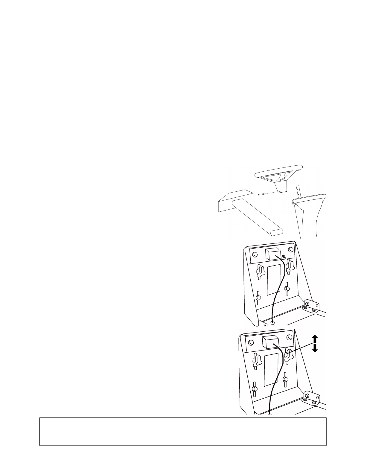
30
4 . MACHINE UNPACKING
The self-propelled mowing machine is delivered in crates reinforced with cratewood. Some machine groups have been dismantled
in the manufacturing plant due to the transport reasons. They will be reassembled before the machine putting into operation. The
machine unpacking and preparation for the operation is carried out by the vendor within the framework of preselling service.
4.1 CHECKING AFTER UNPACKING
After removing the wrapping take down carefully the machine from the pallet - use the ramps otherwise there is a risk of the machine
damage. Check if the machine was not damaged during the transport. Unpack also all dismantled groups and check them.
In the basic packing are delivered:
• mowing machine
• steering wheel
• seat
• documentation (packing list, mowing machine operator‘s manual, engine operating instructions, accumulator operating
instructions, Service book)
4.1.1 DISPOSE OF PACKAGE
After the machine unpacking it is necessary to dispose of the wrapping. When disposing, observe the appurtenant law. Separate
the packing material according to the appropriate packaging catalogue. This procedure can be entrusted to a specialized fi rm.
4.2 PREPARATION FOR PUTTING INTO OPERATION
With respect to the technical character of this work, the mowing machine preparation into operation is carried out by Your vendor
(in accordance with the instructions of the machine manufacturer).
4.2.1 ASSEMBLY OF STEERING WHEEL
Place the machine on an even surface and align the front wheels into straight
direction. Mount the steering wheel and lock it in the corresponding hole of the
chosen position of height by the pin supplied.
4.2.2 ASSEMBLY OF SEAT
Remove the seat wrapping cover. Put the seat on its place in the machine and fasten it by
means of screws being preassembled in the seat.
4.2.3 SEAT POSITION ADJUSTMENT
Adjust the position of the seat in the following way:
Loosen the screws with plastic roses. Shift the seat forward or backward to the desired
position. Retighten the screws with plastic roses.
4.2.4 CONNECTION OF ACCUMULATOR
When putting the accumulator into operation, proceed according to the instructions
stated in the Accumulator operating instructions. The accumulator is placed under the
engine bonnet on the right-hand side of the seat.
Loosen the screws on the accumulator pole outlets.
Connect the red wire to the (+) pole of the accumulator and retighten the screw.
Connect the brown wire to the (–) pole of the accumulator and retighten the screw.
WARNING
Reverse connection of the wires then stated above will result in a damage to the machine.
When disconnecting the accumulator, always disconnect the (–) pole as the fi rst.
Follow the instruction for the maintenance stated in the accumulator operating instructions.
Page 33
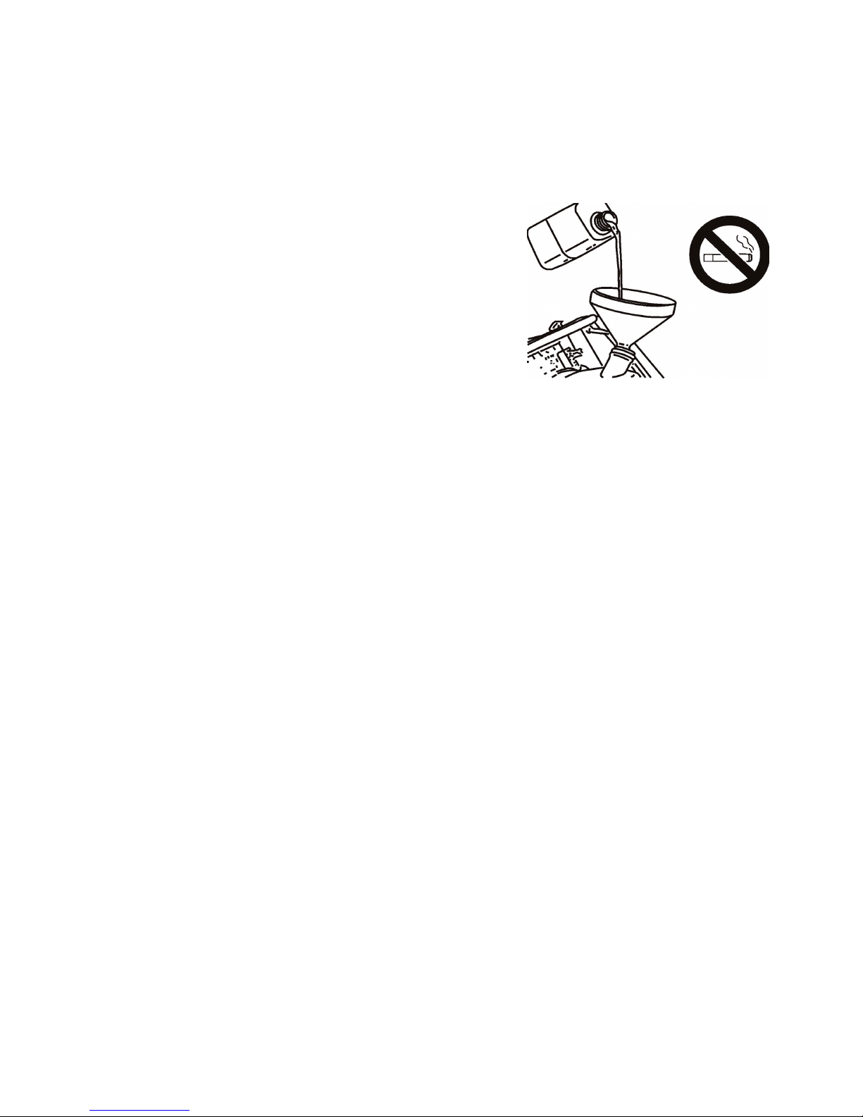
31
5. PUTTING INTO OPERATION
With respect to the technical character of this work, the mowing machine putting into operation is carried out by Your vendor
(in accordance with the instructions of the machine manufacturer).
5.2 CHECK OF OIL LEVEL IN ENGINE
Proceed according to the engine operating instructions, follow all the instructions stated in the chapter 7.1 “Summary of checks
and maintenance”.
5.2 CHECK OF ACCUMULATOR
Perform according to the accumulator operating instructions.
5.3 FILLING THE TANK WITH PETROL
• The machine is transported without fuel for safety reasons.
• Fill the tank only if the engine is turned off and is cold.
• Use only the unleaded petrol with octane number 95 (Natural 95).
• The tank is placed in the column of the seat and is easily accessible after
tilting the seat forwards.
• Open the tank cap slowly as there may be an overpressure of petrol vapours
in the tank.
• When refuelling, use a canister with a funnel.
• Do not overfi ll the tank.
• The petrol level height in tank can be controlled through a slot in the lefthand part of the seat column.
• Always wipe dry the vicinity of the tank cap as well as the cap. Clean also
the whole tank regularly as the contingent impurities in the fuel may cause a
failure.
• When manipulating with the fuel, do not eat, smoke or use naked fl ame.
Page 34
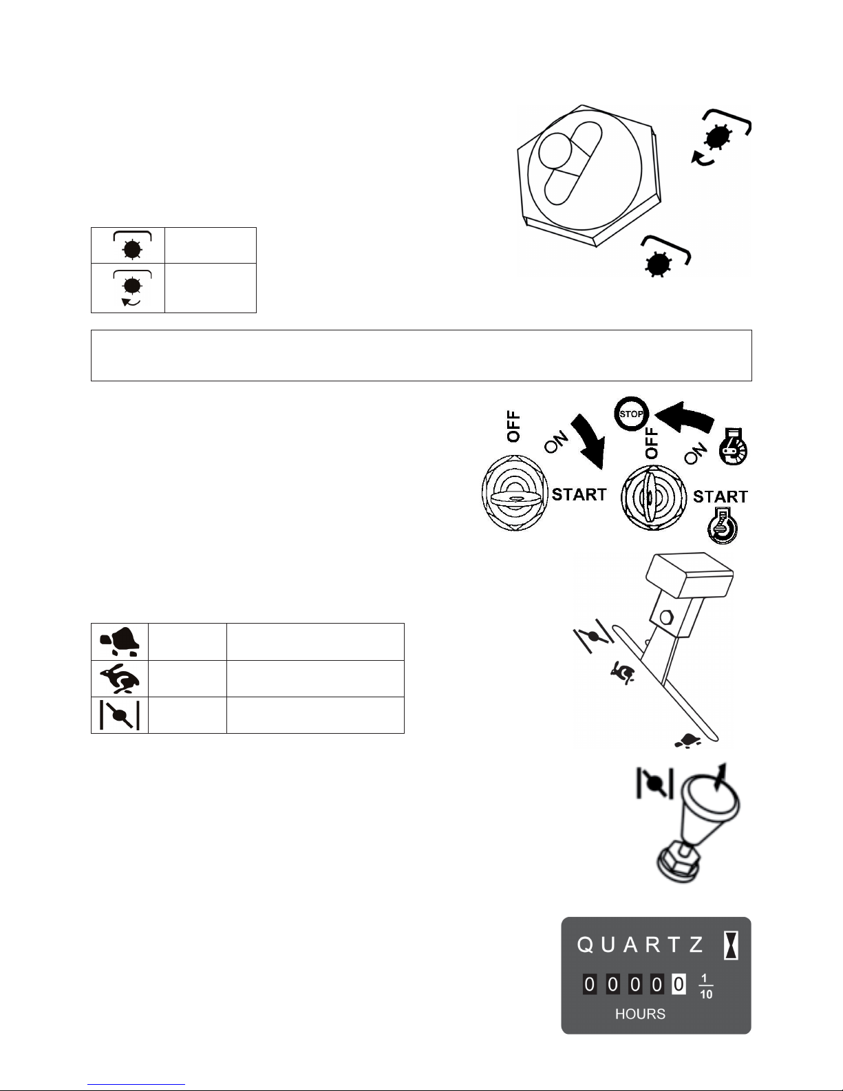
32
6 . MACHINE CONTROL
6.1 DESCRIPTION AND FUNCTION OF
CONTROLS
6.1.1 MOWING MECHANISM SWITCH
The switch of the mowing mechanism switches on the electromagnetic clutch
whose pulley transfers the drive from the engine by means of the V-belt to
the pulley of the mowing mechanism. The switch is locked in “OFF” position
against an unwanted switching on. To switch on, it is necessary to pull out a bit
the switch lever and tip it to the “ON” position.
OFF
ON
CAUTION:
If the mowing mechanism is lifted in the transport position (see the chapter 6.1.6), it is not possible to start the mowing
mechanism drive. The transport position is monitored by means of a safety switch.
6.1.2 SWITCH BOX
The key has 3 positions:
OFF - ignition switched off
ON - ignition switched on
START - engine starting
6.1.3 GAS CONTROL LEVER
It controls the engine revolutions. The individual positions of the lever are, as follows:
MIN Engine idle running
MAX Engine max. revolutions
CHOKE * Engine cold start
* The choke is installed in the machine in dependance on the engine type.
6.1.4 CHOKE
It enables the start of the cold engine. It is installed in the machine in dependance on the engine type.
6.1.5 ENGINE HOUR METER
The engine hour meter is installed in dependance on the machine type. It is in operation
only with the ignition switched on and the seat switch switched on (automatically by the
weight of the operator). Any manipulation with the engine hour meter means the loss of
guarantee. If a failure of the meter occurs, inform Your service immediately.
Page 35
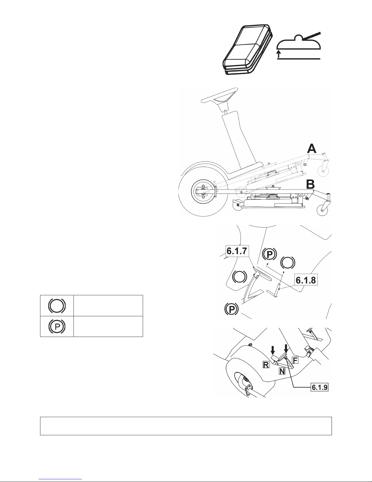
33
6.1.6 SWITCH OF MOWING MECHANISM LIFTING
This switch serves for the mowing mechanism lifting into the transport position
and to its lowering into the working position set by the lever 6.1.11.
Mowing mechanism positions are: A - transport position
B - working position
To lift or lower, depress the switch and keep it depressed.
Release the switch immediately when the end position
is reached. Although the end positions are secured by a
safety clutch, a breakdown of the electrical installation is
threatening in case the switch is kept depressed for a longer
time.
6.1.7 BRAKE
When the brake pedal is fully stepped on, the mowing machine is braked to a
stop. Never use the brake simultaneously with the function of the travel -
a damage of the gearbox is threatening.
6.1.8 PARKING BRAKE LEVER
The parking brake lever has 2 positions. Before shifting the lever into the
“P” position, step on the brake pedal. The disengaging of the parking brake
is executed by stepping on the brake pedal, at this the arrestment of the
lever is automatically released.
Brake released
Brake engaged
6.1.9 TRAVEL PEDAL
It controls the drive of wheels and machine travel speed in both directions.
Forward drive:
Step on slowly the pedal with the toe in the “F“ direction. The bigger
stepping on the higher speed and vice versa.
Backward drive: Step on slowly the pedal with the heel in the “R“
direction. The bigger stepping on the higher speed and vice versa. As
soon as the pedal is relased, it returns automatically into the “N“ (neutral)
position and the machine stops.
WARNING !!!
The change of the drive direction is only possible after the machine stops.
Page 36
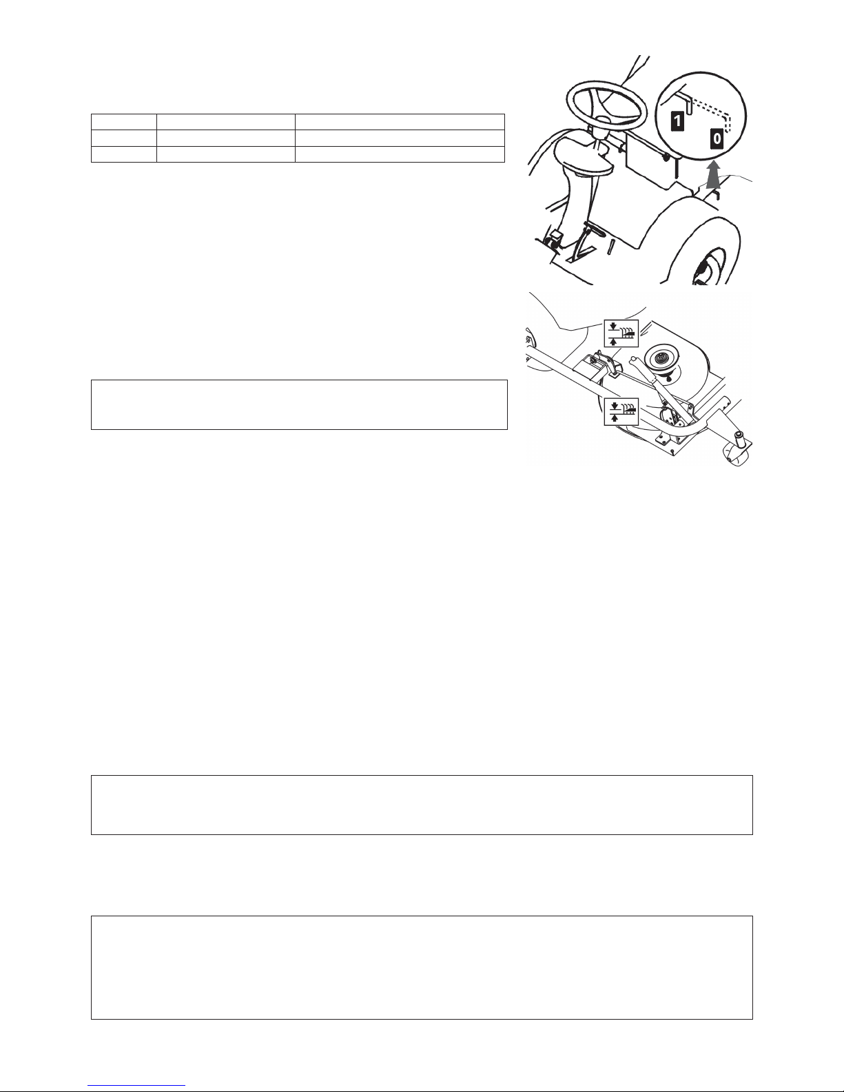
34
6.1.10 BY-PASS LEVER
The by-pass lever serves for disengaging the gear of the front wheels drive.
It has two positions:
Position Front wheels drive Use
0 OFF machine pushing, engine in standstill
1 ON drive, engine running
6.1.11 MOWING MECHANISM HEIGHT SETTING-UP
LEVER
It serves for setting up the mowing mechanism height above the ground. It has 8
working positions corresponding to the height of mowing 3 up to 8 cm. The bigger
the number of the lever position the higher vegetation remains after the mowing.
WARNING:
When driving the machine without mowing, the mowing mechanism
must be lifted into the transport position by means of the 6.1.6 switch.
6.2 OPERATION AND ATTENDANCE
Machine safety protection
The mowing machine is equipped with safety contacts which are closed by the switch placed under the seat. The engine will
automatically stop if the driver leaves the seat. The engine may only be started if the switch of the mowing mechanism switch is
in the „OFF“ position, the mowing mechanism is lifted in the transport position and the travel pedal is not stepped on.
6.2.1 ENGINE STARTING
• Check the petrol level in the tank.
• Sit down onto the machine seat comfortably and lift the mowing mechanism into the transport position by means of the switch
6.1.6.
• Set the mowing mechanism switch 6.1.1 to the „oFF“ position.
• Caution, do not step on the travel pedal 6.1.9.
• Set the gas control lever 6.1.3 to the „MAX“ position.
• Pull out the choke 6.1.4.
• Do not manipulate the mowing mechanism height setting up lever 6.1.11.
• Turn the ignition key 6.1.2 to the “START“ position. The time of starting must not exceed 10 seconds – if this time is
exceeded a damage to the battery threatens.
• The engine „is running“ - let loose the ingnition key. The key will automatically return to the „ON“ position.
• Shift in gradually the choke 6.1.4.
• Set the gas control lever 6.1.3 slowly to the “MIN“ position (reduce the engine speed).
• Let the engine run for several minutes before turning on the mowing mechanism.
DANGER !
Never leave the running engine in a closed or badly ventilated room.
The exhaust fumes containing the carbon monoxide are very dangerous. Keep Your hands, legs and loose clothes
out of the reach of moving parts and of the exhaust.
6.2.2 ENGINE STOPPING
• Set the gas control lever 6.1.3 to the “MIN“ position.
• Turn off the mowing mechanism by the switch 6.1.1 (see the chapter 6.2.4).
• If the engine is overheated, let it running for a while at minimum revolutions.
• Turn off the engine by the key 6.1.2 rotation to the “STOP” position and remove the key from the ignition.
WARNING !!!
Never stop the engine by a mere getting off the seat, as the the key left in the ignition switch may cause a fault of the electrical
instalation. Always rotate the key to the “OFF” position and remove it from the switch box.
IMPORTANT
Before turning the ignition off, reduce the engine revolutions to the slow speed in case the self-ignition will occur, not
observing this instruction may result in a damage to the engine and exhaust.
Page 37

35
6.2.3 MOWING MECHANISM TURNING ON AND OFF
a) Turning on
• Set the gas control lever 6.1.3 to the “MAX” position.
• Lower the mowing mechanism by means of the switch 6.1.6 to the working position set up by the lever 6.1.11, otherwise there
is a risk of the V-belt damage.
• Set the mowing mechanism switch 6.1.1 to the „oN“ position.
The mowing mechanism will be switched on provided the operator is sitting on the machine seat.
b) Turning off
• Set the mowing mechanism switch 6.1.1 to the „oFF“ position.
• If the driver leaves the seat, the engine will stop automatically, and with this also the mowing mechanism.
WARNING !!!
Never switch off the mowing mechanism by mere getting off the seat. Unless You switch over the ignition key from the „ON“
position to the „OFF“ (STOP) position, the part of the electrical installation is still live and this may cause its fault.
6.2.4 MOWING MECHANISM HEIGHT SETTING UP
The mowing mechanism must be lowered into the working position „B“ (see the fi gure in the chapter 6.1.6) by switching over
the switch 6.1.6 to the position of „lowering“.
Shift the mowing mechanism height setting up lever of 6.1.11 upwards if You want to set up the mowing mechanism higher
above the ground, or shift the lever downwards if You want to set up the mowing mechanism closer to the ground.
The position „1“ is used for following the terrain unevenness. Do not use this height setting up permanently as there is a danger
of increased wear of the mowing mechanism parts.
The mowing mechanism is equipped with 3 traversing wheels which lift the frame with mowing mechanism in case of a terrain
unevenness and thus they serve as the protection of mowing knives against a damage.
6.3 TRAVEL
Before the start of travelling step on the brake pedal 6.1.7 to make Yourself sure that the parking brake is disengaged. The parking
brake lever 6.1.8 must not stay in the „P“ position!
The by-pass lever 6.1.10 must be set in the position “1”, i.e. the by-pass of travel must be disengaged.
At travelling to the place where the mowing is to be carried out, the mowing mechanism must be switched off (switch 6.1.1) and
lifted to the transport position by switching over the switch 6.1.6 to the positon of „lifting“.
At crossing the obstacles higher than 8 cm (kerbs, etc.) it is necessary to use the ramps in order to prevent from a damage to the
mowing mechanism and gearbox.
Carry out the drive itself in the followng way:
• Decrease the speed of the engine by shifting the gas control lever 6.1.3 to the „MIN“ position.
• At moving off, step on the travel pedal 6.1.9 slowly in accordance with the desired direction of the drive - at the fast stepping
on the pedal there is a danger of injury.
• The change of the drive direction from forward to backward or vice versa is only possible after the machine is stopped. If the
machine is not stopped there is a danger of the gearbox failure.
• Never use the travel pedal and brake pedal simultaneously - otherwise there is a danger of the gearbox failure.
WARNING !!!
The machine stopping is only possible by a gradual releasing of the foot from the travel pedal and then by
stepping on the brake pedal. At stepping on the brake pedal, the travel pedal is automatically moving to the
neutral position. At this, the braking distance is shorter than 2 m.
6.4 TRAVEL SPEED AND MOWING OF GRASS
Set the gas control lever 6.1.3 to the “MAX“ position. Set up the mowing mechanism height by the lever 6.1.11 (see the chapter 6.2.4).
There is a generally accepted rule that the more wet, higher and denser grass the lower the speed is to be used. If the speed of the
machine is too high, or in the case of a heavy load, the turning speed of knives decreases and the quality of mowing goes down.
If the grass is too high, the mowing should be done several times. The fi rst cut in the maximum height, contingently with reduced
width of mowing, and the next cut already in required height.
We recommend to mow in the longitudinal as well as cross direction. The overlapping of the machine preceding cut enables to
increase the effi ciency of knives, and also the feature of the mowed area will be improved.
Driving on an uneven surface may result in variation of the speed.
With respect to the conditions, we recommend the following speeds:
Vegetation condition Recommended speed
high, dense and wet 2 km/hour
average conditions 3 – 5 km/hour
low, dry vegetation < 5 km/hour
travel with disengaged mowing mechanism < 7 km/hour
6.5 TRAVEL ON A SLOPE
This mowing machine may operate on the slopes up to the gradient of 14° (25%). When working on a slope use always lower
speed of travel. Travel only perpendicularly to the contour line, i.e. upwards and downwards. The travel along the contour
line is not permitted. Control the speed of travelling by means of the gear change lever. Travel downhill and across the obstacles
at lower speed. The change of direction and turning around on a slope requires increased caution. When stopping the machine
on a slope, always use the parking brake. When the machine is being overloaded on slopes of bigger gradient than 14° (25%), it
may result in a serious damage of the gearbox. The machine manufacturer does not bear any responsibility for a defect resulted
from such use of the machine.
Page 38

36
7 . MACHINE MAINTENANCE
7.1 SUMMARY OF CHECKS AND MAINTENANCE
After season - before machine storage
Before season
Every 100 hours
Every 50 hours
Every 25 hours
Monthly
Regularly after each use
After fi rst 5 hours
After fi rst 2 hours
Before each use
Oil level check (gearbox, engine)
OO
Engine oil changing
O O 1,2 O
Fuel fi lter replacement
O
Accumulator maintenance (check of electrolyte level, cleaning)
OO
Adjustment and check of belts
O O 4O O
Check of brake control
OO
Check of tyre pressures
OO
Check of connection of cables (loosened quick-clamping parts)
OO
Mowing machine cleaning
OO
Check of bolted joints
OOO
Check of function of safety switches and elements
O
Check and adjustment of engine running, gearbox, electromagnetic clutch
O
Check and maintenance of air fi lter, sparking plugs, contingently the
replacement
O 1,2
Check of mowing mechanism condition (backlash, alignment of shafts,
check and sharpening of knives)
O O 3
Explanatory notes to table:
1. Change the oil more frequently if the mowing machine is loaded more or if it works at outdoor temperatures about 35°C or higher.
2. Carry out the checking more frequently if the machine works in a dusty environment.
3. Carry out the checking more frequently if the machine works in a sandy environment.
4. Carry out the checking more frequently if a new belt is put on.
7.2 TYRE PRESSURE CHECK
Maintain the specifi ed pressures in the tyres and check them regularly. Different values of pressure can make the travel more
diffi cult and can contingently lead to the loss of control over the machine. Adherence to the prescribed pressure is also important
for the evenness of mowing.
• Pressure in front tyres 80 - 140 kPa
• Pressure in rear tyres 80 - 140 kPa
7.3 MAINTENANCE AFTER WORK
After fi nishing the mowing lift the mowing mechanism to the highest position and switch off the drive of knives. Switch off the
ignition, step on the brake pedal and secure the machine position by the parking brake.
7.3.1 CLEANING
After fi nishing the mowing remove every time all the impurities and remnants of grass from the machine surface as well as from
the mowing mechanism frame.
WARNING !!!
Before starting the cleaning, washing or machine repair, remove the keys from the ignition switch. Always work in solid
shoes, gloves and clothes designed for work. Avoid spilling the fuel, oil or other harmful substances.
7.3.2 WASHING
Avoid washing with water in vicinity of the electrical equipment on the control panel, accumulator, etc. Do not use high-pressure
devices.
Carry out the washing in the following way:
• Wash the mowing machine on an even surface.
• Clean the machine plastic parts using a sponge, water and soap.
• Dismantle the pin 2 and pin 3 (see the fi gure in the chapter 7.13).
• Lift the mowing mechanism, holding it for its frame, into the vertical position. Use a scraper and jet of water to remove the
remnants of grass from the mowing mechanism.
Page 39
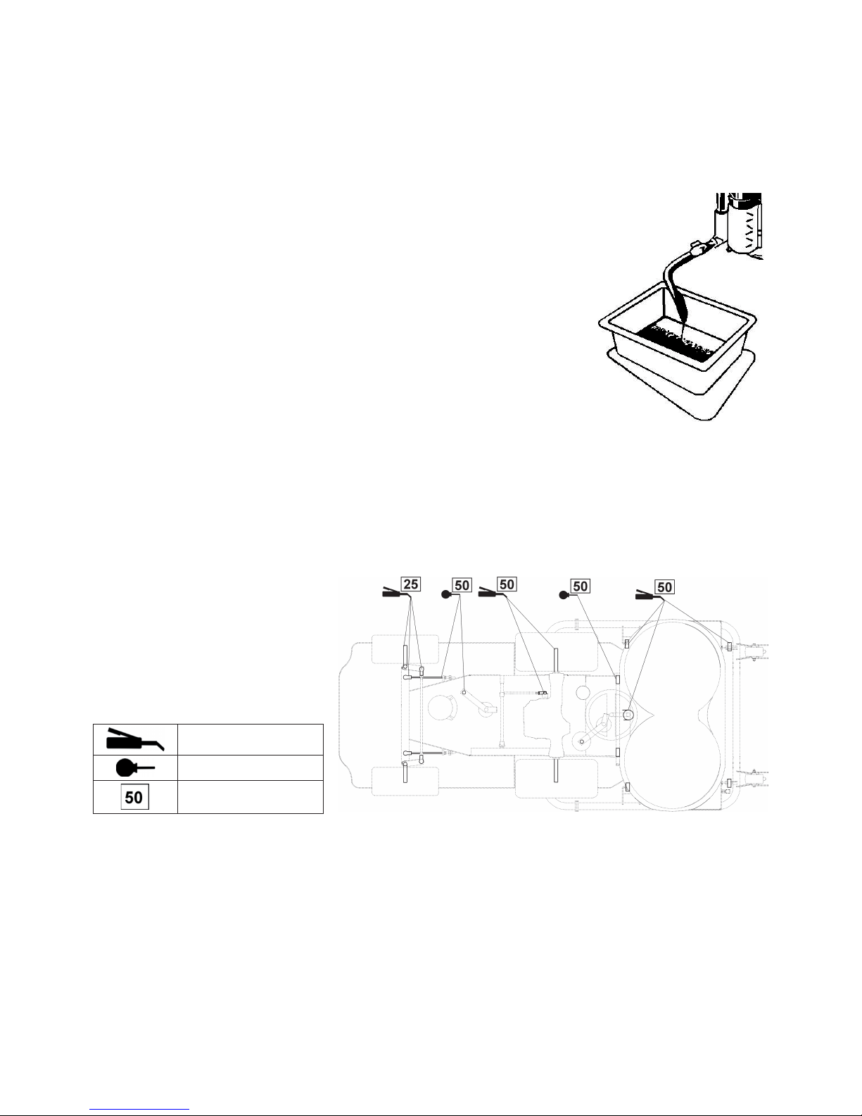
37
7.4 ACCUMULATOR MAINTENANCE
Carry out the accumulator maintenance according to the instructions included in the accumulator operating instructions.
7.5 ENGINE MAINTENANCE
Carry out the engine maintenance according to the instructions included in the engine operating instructions.
7.5.1 CHECK OF OIL LEVEL IN ENGINE
Carry out the check of oil level in engine according to the instructions included in the engine
operating instructions.
7.5.2 OIL CHANGING
The engine is provided with an oil drain screw.
• Place a fl at vessel having capacity of 2 litres minimally and prop up the machine on the
opposite side than the drain screw is in order that all oil will fl ow-out from the engine
• Unscrew the drain screw and release the oil fi ller cap in order that the oil will better and
faster fl ow-out from the engine.
• Screw in the drain screw back, fi ll the engine with the correct quantity of oil specifi ed
(see the engine operating instructions) and close the oil fi ller cap.
• Take the drained oil to the place of the used oils liquidation.
7.5.3 FUEL FILTER REPLACEMENT
Carry out the fuel fi lter replacement according to the instructions included in the engine
operating instructions.
7.5.4 AIR FILTER MAINTENANCE
Carry out the maintenance according to the instructions included in the engine operating instructions.
7.5.5 SPARKING PLUG MAINTENANCE
Carry out the maintenance according to the instructions included in the engine operating instructions.
7.6 LUBRICATION
Carry out the lubrication according to the
lubrication chart, the checks of functions
including the maintenance according to the
summary in the chapter 7.1.
Bearings of tightening rollers, guiding
rollers and bearings of mowing mechanism
are self-lubricating.
Before the machine storage for a longer
time lubricate thoroughly all places which
require the lubrication.
grease
SAE 30 oil
interval in hours
Greasing is used for:
• king pins of wheels moving round
• angular joints of tie rod of travel - dismantling, greasing
• angular joints of pins of wheels - dismantling, greasing
• screw of pull rod of brake - apply grease close to the hole for screw
• screw of pull rod of mowing mechanism lifting - apply grease close to the hole for screw
• angular joints of steering connecting rod - dismantling, greasing
• bearings of rear wheels
• pins of wheels passing through the axle
• centric pivot of rear axle - through the grease cup
• bearings of steering wheel shaft - greasing
• tightening pulley - dismantling and greasing of pins
Oil is used for lubrication of:
• wire rope of steering unit
• pins of mowing mechanism securing
• fulcrums of travel pedal
• fulcrums of brake pedal
Page 40
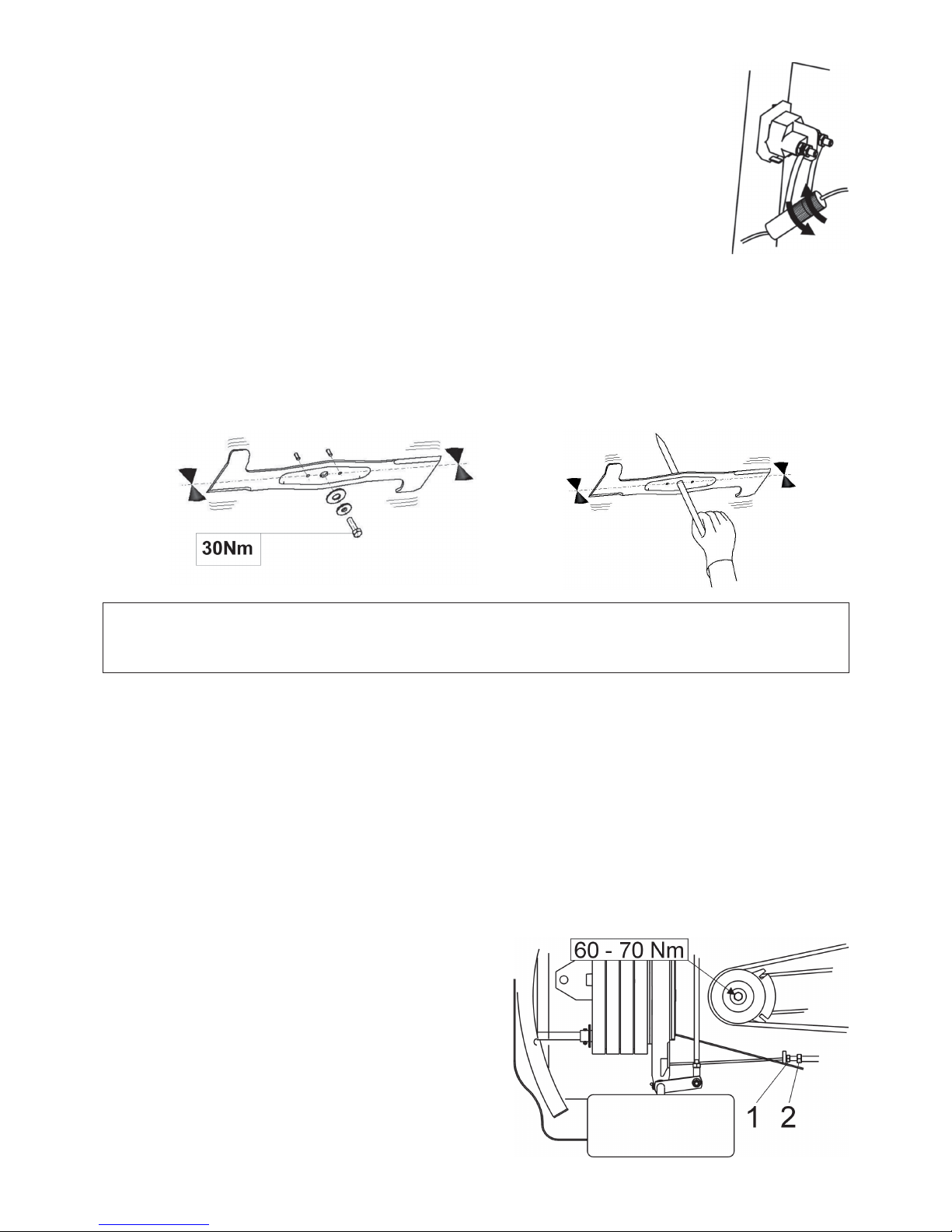
38
7.7 FUSE REPLACEMENT
Lift the front bonnet. Unscrew the sleeve, take out the fuse and insert the new one having the same value
as the original fuse had, i.e. 20 A. If it is not possible to start the engine even after the fuse replacement,
contact the authorized service.
7.8 MACHINE JACKING UP
If You want to jack up the mowing machine, use a jack and supports. At the jacking up proceed as
follows:
• Place the jack under the gearbox and jack up the machine front part.
• Put two supports under both ends of axle inside the front wheels side.
• Jack up the machine front part and put two supports under ends of both king pins.
7.9 REPLACEMENT OF MOWING MECHANISM KNIVES
The mowing knives must be sharp, statically balanced and straight. These conditions are important for the evenness of heigh of
mowing and quality of cut. The blunt cutting edge worsens both the quality of mowing and result of mowed grass collecting.
CAUTION !!!
At the moment the knives hit a solid obstacle, stop the engine immediately and check the knives! The shear pins may be
damaged or cut. Replace the cut pins with new ones provided in the machine equipment. Also check if the fi xing screws of
knives are tightened with the tightening torque specifed.
Replace the knives in the following way:
• Lift the mowing mechanism to the transport position.
• Unscrew both knives, clean them and carry out their sharpening. Check the static balance of knives (see the fi gure above).
• At reassembly see to it that the bendings of the blades are pointing upwards into the housing of the mowing mechanism. Do
not confuse the left knife with the right one. The right knife is provided with the screw having left-hand thread.
• Check the condition of the shear pins which serve as the protection of mowing mechanism against a damage. If the shear pins
are damaged replace them immediately.
• Tighten the fi xing screws of knives thoroughly with the specifi ed tightening torque of 30±3 Nm.
7.9.1 SHARPENING OF KNIVES
The knife may be sharpened with a fi le or a grinder. Do not carry out the sharpening directly on the mowing mechanism.
Pay great attention to the alignment and balancing of knives. The vibrations generated by the unaligned and unbalanced knives
can cause a serious damage to the engine or mowing mechanism.
When balancing, insert a screwdriver into the centring hole and set the knife into the horizontal position (see the fi gure 7.9
above). If the knife remains in this position, it is balanced. If one of the knife ends is overbalancing, carry out the grinding of this
side until the knife is balanced.
The allowable static unbalance may be 2g maximally.
7.10 STEERING UNIT MAINTENANCE
Check the play in the steering regularly. When an excessive backlash
is ascertained, take it up. At the backlash taking up, fi rst, straighten
the wheels into the direct direction. Loosen the nut 1 and take up the
backlash to the minimum by turning the adjusting screw 2 at the end
of wire rope. Then, retighten the nut 1 fi rmly. Carry out the same
adjustment at the other end of the chain. See to it that the wire ropes
on both ends of the chain are tightened equally.
Page 41
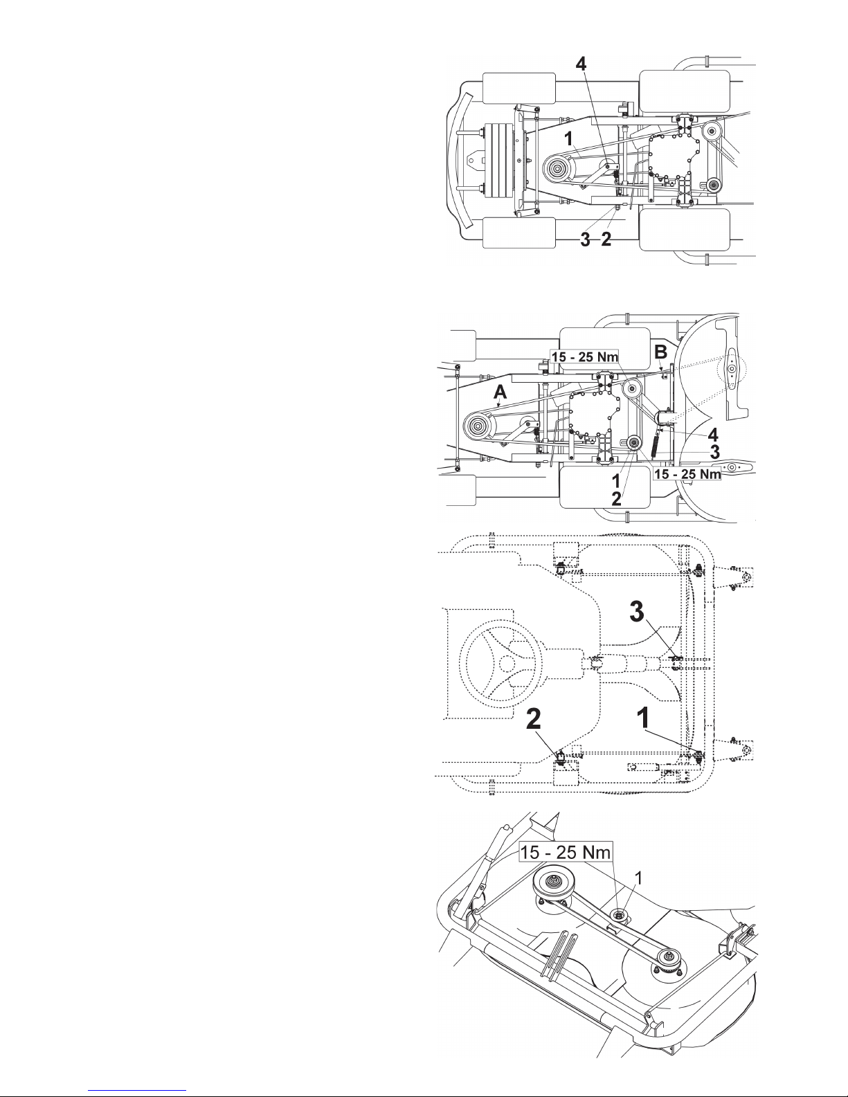
39
7.11 CHECK AND ADJUSTMENT OF
TRAVEL DRIVE BELT
The belt 1 is tensioned correctly if it sags approx. by 1.5 cm when
the force of 4 kg is applied in the middle distance between pulleys.
The adjusting of the belt tension is to be carried out by turning the
nut 3 after loosening the nut 2 on the screw tightening the tension
spring. After fi nishing the adjustment, retighten the nut 2.
7.12 CHECK AND ADJUSTMENT OF
MOWING MECHANISM DRIVE V-BELTS
V-belt A:
The V-belt is tensioned correctly if it sags approx. by 1.5 cm
when the force of 4 kg is applied in the middle distance between
pulleys. The adjusting of the belt tension is to be carried out by
shifting the pulley 2 after loosening the nut 1. After fi nishing the
adjustment, retighten the nut 1.
V-belt B:
The V-belt of the mowing mechanism drive is tensioned by means
of a pulley with a spring. If the tension releases due to the working
stress of the belt, displace the suspension eye of the spring 3 into
the second hole in the arm 4 of the tensioning pulley.
7.13 MOWING MECHANISM
WITHDRAWAL FROM MACHINE
• Lower the mowing mechanism to the working position by
depressing the switch 6.1.6. Release the switch immediately
when the end position is reached.
• Release the V-belt by pulling the tensioning pulley arm 4
(fi g. 7.12) and remove the belt.
• Take out the spring 3 (fi g. 7.12) from the arm of the tightening
pulley.
• Drag out the resilient cotter pins from the front pins 2 and
both rear pins 1 of the mowing mechanism suspension.
• Dismantle the pin 3 and the screw of the mowing mechanism
lifting.
• Shift out both rear pins 1 of the mowing mechanism
suspension by means of a pliers.
At the shifting out be careful in order not to injure Your
hands or fi ngers.
• Shift out the front pins 2 of the suspension.
• Slowly withdraw the mowing mechanism from the machine.
7.14 ADJUSTMENT OF KNIVES
DRIVE INDENTED BELT
• Lower the mowing mechanism to the working position by
depressing the switch 6.1.6. Release the switch immediately
when the end position is reached.
• Dismantle the protective cover of the indented belt.
• Loosen the nut 1 and tension the belt by shifting the tensioning
pulley.
• Check the tension. The belt is tensioned correctly, if it sags
approx. by 0.5 cm when the force of 4 kg is applied in the
middle distance between pulleys.
• Retighten the nut 1 and attach the protective cover.
Page 42
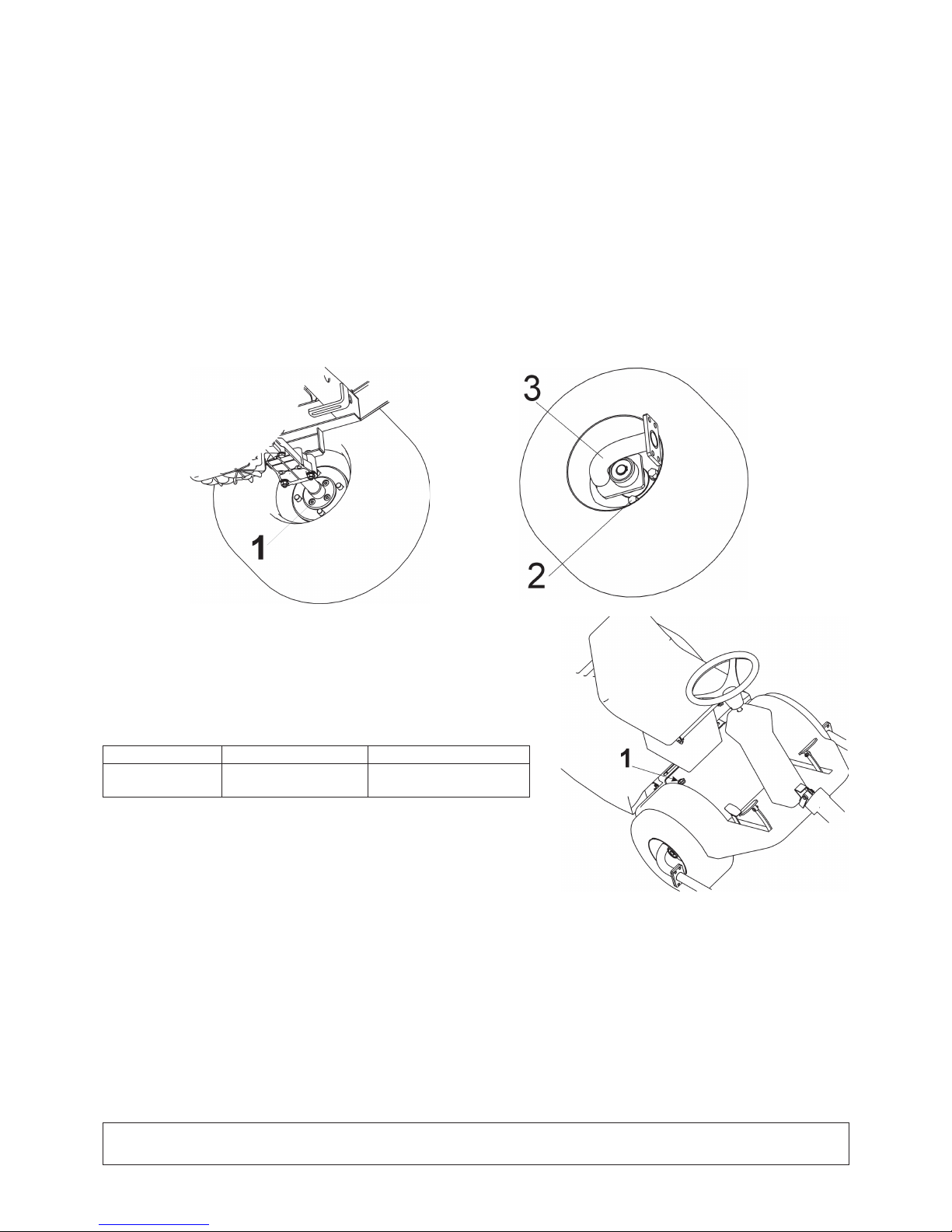
40
7.15 REPLACEMENT OF BELTS
It is rather demanding operation, entrust it to the authorized service.
7.16 WHEEL CHANGING
• Before changing any of the wheels, stop the engine and remove the key from the ignition.
• Jack up the machine and put the supports under it by the procedure described in the chapter 7.8.
• Lower the mowing mechanism to the working position by depressing the switch 6.1.6. Release the switch immediately when
the end position is reached.
• When changing the front wheel, withdraw the mowing mechanism from the machine (see the chapter 7.13) and disconnect
the front frame of the mowing mechanism.
• Release the V-belt B (fi g. 7.12) by pulling the tensioning pulley arm 4 and remove the belt.
• Unscrew the four screws 1 on the inner side of the wheel, remove the retaining ring, the washer and withdraw the holder of
the front frame 3.
• Unscrew the four screws 4 šrouby 2 and take the wheel down.
• When changing the rear wheel, take down the protective cover from the wheel, remove the retaining ring, the washer and pull
the wheel down from the shaft
At the reassembly of the front or rear wheel, use the reverse procedure than at its dismantling.
Before putting the wheel on, clean all parts and lubricate the contact surfaces slightly with grease.
7.17 HYDROSTATIC GEARBOX
MAINTENANCE
To ensure the reliable function of the gearbox it is necessary to keep the oil
level in the correct height. The prescribed values are stated in the table below.
The fi lling hole 1 is in the vicinity of the seat (see the fi gure). If problems
with the gearbox occur contact immediately the authorized service, otherwise
the danger of a serious damage to the gearbox threatens.
Gearbox type Oil specifi cation Oil level
TUFF-TORQ K46 SAE 10W-30, API CD minimally in the half of
equalization tank height
7.18 BRAKE ADJUSTMENT
If the brakes start to lose their effi ciency, entrust their adjustment to the
authorized service.
7.19 OVERVIEW OF TIGHTENING TORQUES OF SCREW CONNECTIONS
Mowing mechanism: Chapter:
Centre screw of knife .............. 30 ± 3 Nm 7.9
M12 nut of tensioning pulley of mowing mechanism drive .............. 45 - 55 Nm 7.14
M8x20 screw of tensioning pulley arm of mowing mechanism
drive belt .............. 25 - 35 Nm 7.14
Engine:
Screw of electromagnetic clutch .............. 60 - 70 Nm 7.10
Screw of holder of tensioning pulley of travel drive belt …........... 25 – 35 Nm 7.11 (no. 4)
WARNING!!!
When any of the self-locking nuts was unscrewed, then at the reassembly, it is always necessary to replace it with the new one.
Page 43

41
8. REMOVAL OF FAILURES AND DEFECTS
Do not execute the service operations unless You have the appropriate technical equipment and qualifi cation. The operations
mentioned below may be executed by the machine user. Other servicing operations not mentioned here but executed by the user
invalidate the guarantee. The manufacturer disclaims any responsibility for damages arisen owing to the low-quality execution
of unpermitted service operations by the user.
Failure, defect Removal
Mowing knives are
mowing unevenly
Remove the accumulated grass from bottom side of mowing mechanism.
Make sure that the knives are sharp and not deformed.
Check the tightening of knives.
Check if the mowing mechanism height setting up corresponds to the data in the chapter 6.1.11 and
6.2.4. If not, carry out the new setting up.
Check the tension of drive belts according to the chapter 7.12 and 7.14. If need be, carry out the
adjustment of tensioning.
Check the shafts of knives. If they are damaged or excessively worn out, replace them.
Check the bodies of bearings for a possible damage. With respect to the fi nding, carry out the repair or
replace them.
Unmowed stripe
remains between
rotors with knives
An unmowed stripe may remain when mowing dense grass or grass with excessively wet surface.
The travel speed shoud be adjusted to the mowing conditions by selecting the suitable gear. The
engine should run with the gas control lever in the „MAX“ position.
Check the knives if they are sharp and undamaged. If necessary, replace them.
Check the tension of drive belts according to the chapter 7.12 and 7.14. If need be, carry out the
adjustment of tensioning.
Check the bodies of bearings for a possible damage. With respect to the fi nding, carry out the repair or
replace them.
Knives of mowing
mechanism are
tearing out sods
Check the setting-up of the height of mowing, and if need be, adjust it. Sods are torn out more often
on uneven surfaces.
Check the bodies of bearings for a possible damage. With respect to the fi nding, carry out the repair or
replace them.
Check if the knives are not bent. If need be, replace them.
Drive belt of
mowing mechanism
is stopping during
operation
A damage to the mowing mechanism drive belt may occur when it jumps out of the pulley during
machine running. If it jumps out even after the check according to the following steps, it has to be
replaced.
- Check the tension of drive belt according to the chapter 7.12. If need be, carry out the adjustment of
tensioning.
- Check the belt guiding.
- Check the setting up of the height of mowing, if need be, adjust it.
- Find out if a foreign object is not obstructing the running of the belt. If it is so, remove the foreign
object.
- Check all the pulleys. Bent or cracked pulleys could cause problems. If need be, replace them.
- Check the inside surface of the pulley fi xed on the engine. If it is rough or there are cracks on it, it is
necessary to replace the pulley.
- Check the wear of tensioning mechanism components. If need be, replace the worn out components.
Drive belt of mowing
mechanism is
slipping
If the grass is too high or wet, the mowing mechanism drive belt may slip.
Check the belt for wear. If it is worn out, replace it.
Check the tension of drive belt according to the chapter 7.12. If need be, carry out the adjustment of
tensioning.
Check the tension spring of tightener of the mowing mechanism drive belt.
Replace the stretched or damaged spring.
Drive belt of mowing
mechanism is being
worn out excessively
Check all places of the belt guiding.
Find out if a foreign object is not obstructing the running of the belt. If it is so, remove the foreign
object.
Check the pulleys. If they are damaged, replace them.
Check the setting-up of the height of mowing, if need be, adjust it.
Check the tension of drive belt according to the chapter 7.12. If need be, carry out the adjustment of
tensioning.
Knives cannot be put
into motion
Check whether the belt is worn out or damaged. If it is so, replace it. If it is slack, tension it.
Check the spring of the tensioning mechanism. Replace the stretched or damaged spring.
Find out if a foreign object is not obstructing the running of the belt. If it is so, remove the foreign
object.
Knives are stopping
with delay
Check the tension of drive belt according to the chapter 7.12. If need be, carry out the adjustment of
tensioning. If it is not possible to tension the belt more due to its considerable wear, t on the new belt.
Find out if a foreign object is not obstructing the running of the belt. If it is so, remove the foreign
object.
Check the function of the electromagnetic clutch, if its disengaging is right. In case of a wrong
function let the authorized service do the replacement or repair.
Page 44

42
Extreme vibration
occurs at turning
on the mowing
mechanism drive
Check the knives if they are not uneven or twisted, check also if they are balanced. In case they are
distorted, replace them.
Check if there are burned spots or irregularities on the belt as they can be the cause of vibrations.
Replace the damaged belt.
Check the knives if they are they are not worn out ordamaged. If need be, replace them.
Check the function of the electromagnetic clutch, if its engaging is right. In case of a wrong function
let the authorized service do the replacement or repair.
Check the inside surface of the pulley fi xed on the engine. If it is rough or there are cracks on it, it is
necessary to replace the pulley.
Check the bottom of mowing mechanism for a deposit of grass. The deposit must be removed.
Check if there is not a fault in the attachment of the engine. If need be, retighten or replace the engine
attaching screws.
Check the tension of drive belt according to the chapter 7.12. If need be, carry out the adjustment of
tensioning.
Machine travel belt is
slipping
Check the tension of travel drive belt according to the chapter 7.11. If need be, carry out the
adjustment of its tensioning.
Check the belt for a damage or wear.
Check the travel clutch mechanism if it is not blocked by a foreign object. If it is so, remove the object.
Check if the pulley of the engine or gearbox is not damaged. Replace the pulley according to the need.
Machine travel belt is
squeaking
Check the tension of travel drive belt according to the chapter 7.11, and function of the brake. If need
be, adjust the belt tensioning. If the function of the brake is not right let the authorized service do the
brake adjustment.
Machine travel belt
jumps out during
operation
Check the tension of travel drive belt according to the chapter 7.11. If need be, carry out the
adjustment of its tensioning.
Check the belt guiding. If need be, carry out the adjustment.
Check the pulleys if they are not damaged. If need be, replace them.
Check the gap of the travel clutch mechanism. In case of deviations, the bracket of the clutch pulleys
may be defl ected. If need be, replace it.
Machine does not
move when the travel
pedal is stepped on
Check the tension of travel drive belt according to the chapter 7.11. If need be, carry out the
adjustment of its tensioning.
Check the pulleys of the engine and gearbox with regard to the sheared or damaged grooves. If need
be, replace them.
Extreme vibration
occurs at driving
Check the pulleys if they are not damaged or distorted. If need be, replace them.
Check the belt for burned spots or other irregularities. If need be, replace the belt.
Check the tension of travel drive belt according to the chapter 7.11. If need be, carry out the
adjustment of its tensioning.
Check the balance of the mowing knives. If need be, balance or replace them.
Engine does not run Check if there is the petrol in the tank.
Check if the prescribed procedure of the engine starting was adhered to (see the chapter 6.2.1).
Check the fuse.
Check if the voltage on the accumulator poles is 12 V. At the new machine check if the accumulator
was activated and charged.
At the new machine remove the sparking plug and check if there is not oil cumulated as a result of
wrong manipulation.
Check if all connections of conductors are in order, and if the switches of electric system are
functional.
Test the engine meticulously according to the Engine operating instructions elaborated by its
manufacturer.
Have the machine electric system tested in a special workshop.
Engine rotates but
does not start
Check if the prescribed procedure of the engine starting was adhered to (see the chapter 6.2.1).
Check if the petrol in the tank is clean.
Check if the fuel lter is not clogged.
Make sure that the gas control lever is in the “CHOKE” position.
Test the engine meticulously according to the Engine operating instructions elaborated by its
manufacturer.
Have the cabling and switches tested in a special workshop.
Machine cannot be
pushed or can be with
di culties only
Check if the by-pass lever is in the „0“ position.
„Whistling“ can be
heard during travel
Check the condition of belts, and guide and tension pulleys.
If the problems persist, contact the authorized service immediately.
8.1 SPARE PARTS ORDERING
We recommend to use only the original spare parts which ensure the safety and replaceability. Always order the spare parts at
the authorized dealer or service organization which are informed of the actual technical changes executed in the products during
the manufacture. In the order always state the serial number to enable the easy, quick and exact identifi cation of the needed
spare part. You will fi nd the serial number recorded on the second page of this manual cover. State also the year of the machine
production which is included on the identifi cation plate located under the seat.
8.2 GUARANTEE
The conditions of guarantee are specifi ed on the certifi cate of guarantee which is always handed over with the product at the dealer.
Page 45

43
9. AFTER-SEASON MAINTENANCE, MACHINE STORAGE
After the end of the season, or if the machine is not used for more than 30 days, it is advisable to prepare it immediately for the
storage.
If the fuel stays in the tank without a motion for more than 30 days, sticky sediment may come into being. This can have an
adverse effect upon the carburettor and be a cause of the wrong funcion of the engine. That is the reason for emptying the tank.
WARNING !!!
Never store the mowing machine with the full tank inside the buildings or in badly ventilated
spaces where there are fuel vapours, naked fl ame, sparking or ignition fl ames, furnace, central heating, dry rags, etc.
Handle the fuels and lubricants carefully as they are highly combustible, and a careless handling may cause serious
burns to You or damage to the property.
Carry out the emptying of the tank only into the approved vessel outdoor without naked fl ame.
Recommended procedure of preparations for the mowing machine storage:
• Clean the whole machine thoroughly.
• Replace the faulty or worn out parts and tighten all loosened screws and nuts.
• Prepare the engine for the storage according to the engine operating and maintenance instructions.
• Lubricate all lubricating points according to the lubricating plan (see the chapter 7.13).
• Slacken the V-belt of the mowing mechanism drive (see the chapter 7.9.1)
• Take out the accumulator, clean it, refi ll it with distilled water up to the lower parts of fi lling holes rings and charge it
fully. Uncharged accumulator may freeze and burst. Store the accumulator, if need be, in a cold and dry place. Charge the
accumulator every 30 days and check its voltage regularly.
• Store the mowing machine covered in a clean and dry place.
The best way how to ensure the maximum serviceability of the mowing machine for the next season is an annual check and
adjustment by the authorized service.
10. MACHINE DISPOSAL
The mowing machine user is obliged to dispose the machine after the end of its service life. This may be done in two ways:
a) To hand the machine over to a fi rm which is engaged in this activity (scrap yard, car cemetery, etc.) You will receive the due
document of handing the machine over to the disposal.
b) To dispose the machine by Yourself. In this case we recommend to proceed in the following way:
• Carry out the disposal with utilization of the secondary raw materials in accordance with the applicable enactment on waste
materials.
• Dismantle the machine completely.
• Clean the parts which can be still utilized, conserve and store them for further use.
• Separate the other parts to the parts ecologically unharmful and to the parts endangering the environment, e.g. the rubber
parts (sealing rings), residues of lubricants in bearings or gearings. Ecollogically harmful components have to be treated
in accordance with the applicable enactment on waste materials valid in the country of the machine user, e.g. in the Czech
republic it is the Law on waste materials no.185/2001 Sb.
• Separate the disposed material according to the Waste catalogue in compliance with the applicable regulation. Ecollogically
unharmful parts may be treated as the scrap.
Page 46

44
Seco GROUP a.s. continues all the time the development and improvement of all machines being manufactured, therefore
the text and illustrations in this manual may vary from the reality. No claims may be deduced of that. Printing, reproduction,
publishing and translantion (even partial one) is prohibited without consent in writing by the Seco GROUP a.s. The changes
are reserved.
Page 47

45
INHALT
EU GLEICHHEITSERKLÄRUNG ................................... 46
VORWORT .......................................................................47
1. Schutz und Sicherheit bei der Arbeit ................ 48
1.1 Sicherheitsanweisungen ..................................... 48
Gra sche Darstellung
von Warnungen und Hinweisen ........................ 49
1.1.1 Arbeit in Hanglagen ........................................... 49
1.1.2 VERBOTE .......................................................... 49
1.1.3 Sicherheit von Kindern ...................................... 49
1.1.4 Brandschutz ....................................................... 49
2. Benutzung und technische Beschreibung .........50
2.1 Benutzung des Gerätes....................................... 50
2.2 Technische Beschreibung ...................................50
2.2.1 Rahmen .............................................................. 50
2.2.2 Motor und Elektrik ............................................50
2.2.3 Getriebe und Vorderradantrieb .........................50
2.2.4 Hinterachse mit Rädern und Lenkung .............. 50
2.2.5 By-Pass ............................................................... 50
2.2.6 Verkleidungen und Bedienteile .........................50
2.2.7 Mähwerk ............................................................. 50
2.3 Bezeichnung ....................................................... 50
3. Technische Parameter ........................................ 51
4. Auspacken .......................................................... 52
4.1 Kontrolle nach dem Auspacken .........................52
4.1.1 Entsorgung der Verpackung .............................. 52
4.2 Vorbereitung zur Inbetriebnahme ....................52
4.2.1 Montage des Lenkrads .......................................52
4.2.2 Montage des Sitzes .............................................52
4.2.3 Einstellung der Sitzposition ..............................52
4.2.4 Anschluss der Batterie .......................................52
5. Inbetriebnahme..................................................53
5.1 Kontrolle des Ölstandes des Motors .................. 53
5.2 Kontrolle der Batterie ........................................ 53
5.3 Füllen des Benzintanks ......................................53
6. Bedienung des Gerätes ....................................... 54
6.1 Beschreibung und Funktion der Bedienteile .... 54
6.1.1 Schalter des Mähwerkes .....................................54
6.1.2 Zündschloss ........................................................ 54
6.1.3 Gaspedal ............................................................54
6.1.4 Kaltstartanlage ...................................................54
6.1.5 Anzeiger der Motorstunden ..............................54
6.1.6 Schalter zum Anheben des Mähwerkes .............55
6.1.7 Bremse ................................................................55
6.1.8 Handbremshebel ................................................ 55
6.1.9 Fahrpedal .......................................................... 55
6.1.10 Hebel BY-PASSU ................................................ 56
6.1.11 Hebel zum Einstellen der Arbeitshöhe .............. 56
6.2 Betrieb und Bedienung ...................................... 56
6.2.1 Anlassen des Motors .......................................... 56
6.2.2 Abstellen des Motors .......................................... 56
6.2.3 Ein- und Abschalten des Mähwerkes .................57
6.2.4 Einstellung der Arbeitshöhe des Mähwerkes ....57
6.3 Fahren .................................................................57
6.4 Geschwindigkeit der Fahrt
und das Rasenmähen .........................................57
6.5 Fahren am Hang ................................................. 57
7. Instandhaltung ................................................... 58
7.1 Übersicht über die Kontrollen
und Instandhaltungen .......................................58
7.2 Kontrolle des Reifendruckes ..............................58
7.3 Instandhaltung nach der Arbeit ........................58
7.3.1 Säubern ............................................................... 58
7.3.2 Waschen .............................................................. 58
7.4 Instandhaltung der Batterie ............................... 59
7.5 Instandhaltung des Motors ................................ 59
7.5.1 Kontrolle des Ölstandes des Motors ..................59
7.5.2 Ölwechsel ........................................................... 59
7.5.3 Austausch des Benzin lters ............................... 59
7.5.4 Wartung des Lu lters ......................................59
7.5.5 Wartung der Zündkerzen .................................. 59
7.6 Schmierung ........................................................59
7.7 Austausch der Sicherungen ............................... 60
7.8 Anheben des Gerätes ..........................................60
7.9 Austausch der Messer des Mähwerkes ...............60
7.9.1 Schärfen der Messer ........................................... 60
7.10 Wartung der Lenkung ........................................ 60
7.11 Kontrolle und Einstellung
des Riemenantriebs ............................................61
7.12 Kontrolle und Einstellung
des Riemenantriebs des Mähwerkes ..................61
7.13 Auswechseln des Mähwerkes .............................61
7.14 Einstellung des Zahnriemens
des Messerantriebs ............................................. 61
7.15 Wechsel der Riemen ........................................... 62
7.16 Radwechsel .........................................................62
7.17 Wartung des Getriebes ....................................... 62
7.18 Einstellung der Bremse ...................................... 62
7.19 Übersicht der Anzugsmomente
der Schraubenverbindungen ............................. 62
8. Abstellung von Störungen und Fehlern............. 63
8.1 Bestellung von Ersatzteilen ................................64
8.2 Gewährleistung .................................................. 64
9. Nachsaisonale Wartung und Einlagerung .........65
10. ENTSORGUNG DES TRAKTORS ....................65
Page 48

46
EU GLEICHHEITSERKLÄRUNG
nach: Richtlinie c.98/37/EC (Regierungsaufl age NV 24/2003 Sb.)
Richtlinie c.89/336/EC (Regierungsaufl age NV 18/2003 Sb.)
Richtlinie 2000/14/EC (Regierungsaufl age NV 9/2002 Sb.)
A. Wir, die : Seco GROUP a.s., Pobřežní 44/362, Praha 8
Zweigbetrieb 02 AGS Jičín, Jungmannova 11
IČO: 60193450
Wir geben auf eigene Verantwortung dieses Bekanntmachung heraus:
B. Ausrüstung
- Bezeichnung : Rasentraktor
- Typ : AP 105
Beschreibung:
AP 105 ist ein vierrädriger Rasentraktor mit einem Motor Briggs & Stratton 17,5HP. Der Antrieb erfolgt über ein stufenloses
Getriebe und Riementrieb und eine elektromagnetische Kupplung zum Mähwerk. Das Mähwerk ist einrotorig ( 2 Messer) mit
vertikaler Achse und einer Mähbreite von 1050 cm. Das Gemähte wird auf der Erde verteilt.
C. Vorschriften, mit denen eine Gleichheit erzielt wurde:
ČSN EN ISO 12 100-2, ČSN EN 55 012, EN 836+A1,2,3, ČSN ISO 4254-1, ČSN EN ISO 11 201, ČSN EN ISO 3767-1,3
D. Die Gleichheit wurde nach folgenden Richtlinien festgestellt:
- Richtlinie 98/37/EC, Seite 8, Absatz 2 a), ( §3, Absatz 1 a), NV č. 170/1997 Sb.)
- Richtlinie 89/336/EEC, Seite 10, Absatz 1, (. §4, Absatz 1, NV č. 169/1997 Sb.)
- Richtlinie 2000/14/ES, Beilage VIII
E. Wir bestätigen, dass:
- dieses Gerät mit den oben defi nierten Angaben über Gleichheit und den oben angegebenen technischen Angaben im
herkömmlichen Gebrauch s i c h e r ist.
- alle Bemühungen zur Absicherung der Gleichheit aller Produkte mit der technischen Dokumentation und den Erfordernissen
der technischen Vorschriften.
- die Lautstärke bei 100 dB(A) liegt.
Erhöhte Lautstärkepegel nach den verwendeten Motoren:
Motor Umdrehungen (min-1) Erhöhte Lautstärke nach akt. Leistung [dB(A)]
Briggs & Stratton 17,5 HP
VANGUARD
2700±100 98,32
Die technische Dokumentation im Umfang nach Anlage V zur Richtlinie 98/37/EC und 2000/14/EC ist beim Hersteller unter
folgender Adresse hinterlegt:
Seco GROUP
Zweigstelle 02 AGS
Jungmannova 11
506 48 Jičín
Ing. Petr Fischer
Vorstandsvorsitzender
Jičín , den 1.4.2005
Page 49

47
VORWORT
Sehr geehrte Kunden,
wir danken Ihnen für Ihre Entscheidung ,sich für den Kauf unseres Produktes entschieden zu haben. Firma Seco GROUP a.s. als
Vertreter der Firmen Knotek und spol., Agrostroj und AGS Jičín ist weltweit für die Herstellung qualitativ hochwertiger Geräte
zur Rasenpfl ege der Marke AGS bekannt.
Unser Ziel ist die Herstellung von hochwertigen und leistungsfähigen Rasenmähern. Wir sind davon überzeugt, dass, wenn Sie
die Möglichkeit hatten, unser Gerät auszuprobieren, Sie damit übereinstimmen, dass uns dies gelungen ist.
Jetzt liegt es schon an Ihnen, mit diesem Gerät so zu arbeiten, das es lange zu Ihrer Zufriedenheit dient.
Lesen Sie sorgfältig diese Anweisung. Gehen Sie genau nach diesen Anweisungen vor, damit sowohl die Benutzung erleichtert
wird, als auch eine optimale Ausnutzung und lange Lebensdauer.
Benutzen Sie diesen Rasenmäher nur zu dem Zweck,zu dem er hergestellt wurde. Jede Benutzung ausserhalb dieses Bereiches
kann zu einer Beschädigung des Traktors führen bzw. für Sie selbst unsicher sein. Dies kann eine Nichtanerkennung von
Garantieleistungen zu Folge haben,weil der Hersteller in solchen Fällen die Verantwortung ablehnt.
In unseren mehr als 100 autorisierten Servicestationen in ganz Europa stehen Ihnen Techniker zur Verfügung ,die vom Hersteller
ausgesucht und geschult worden sind.
Page 50

48
1. SCHUTZ UND SICHERHEIT BEI DER ARBEIT
Der selbstfahrende Rasentraktor AP 105 mit dem Markennamen FRONTJET wurde nach gültigen europäischen Sicherheitsnormen
hergestellt.
1.1 SICHERHEITSANWEISUNGEN
Vor der ersten Benutzung bitte sorgfältig die Gebrauchsanweisung lesen. Bei der Arbeit mit dem Mähwerk sind die
Sicherheitsvorschriften aus dieser Anleitung einzuhalten. Im Falle, das dieses Gerät im Widerspruch zu den dort aufgeführten
Anweisungen oder Sicherheitsbestimmungen benutzt wird, übernimmt der Hersteller keine Verantwortung für eventuell
entstehende Schäden und der Benutzer verliert das Recht auf Gewährleistung.
Achtung !
Im Falle, das Sicherheitsbestimmungen nicht eingehalten werden ist es möglich das es durch das Mähwerk
zu ernsten Verletzungen kommen kann. Fassen Sie nicht unter die Abdeckung des Mähwerks.
Nähern Sie sich niemals mit Ihren Körperteilen den rotierenden Messern oder anderen beweglichen Teilen des Gerätes.
Benutzen Sie das Gerät nicht, wenn es beschädigt ist bzw. Teile der Schutzeinrichtung fehlen. Alle Abdeckungen und alle Teile
der Schutzeinrichtung müssen immer an ihren Plätzen sein. Beseitigen Sie deshalb keine Schutzeinrichtungen des Gerätes.
Kontrollieren Sie regelmässig die Schutzeinrichtungen des Gerätes.
Am Gerät und seinem Zubehör dürfen ohne Herstellerfreigabe keine technischen Änderungen vorgenommen werden.
Ungenehmigte Änderungen können zur Verletzung von Sicherheitsvorschriften und zum Verlust der Gewährleistung führen.
Ändern Sie nicht die Motorregulierung bzw. manipulieren Sie nicht am Motordrehzahlbegrenzer.
Entfernen Sie keine Sicherheitsaufkleber oder Schilder.
Machen Sie sich vor der Inbetriebnahme intensiv mit der Bedienung des Gerätes vertraut,damit Sie im Notfall das Gerät sofort
abstellen können.
Halten Sie das Gerät und das Zubehör in einem sauberen und technisch guten Zustand.
Das Gerät darf nur von Personen älter als 18 Jahre bedient werden,die mit der Bedienungsanleitung vertraut sind.
Das Gerät darf nicht bei Hanglagen von mehr als 14° (25%)eingesetzt werden.
Der Benutzer ist für die Sicherheit von Personen verantwortlich ,die sich im Arbeitsbereich des Gerätes befi nden.
Bewegen Sie sich nicht unter oder neben dem Gerät ,wenn es nicht ausreichend gegen Überschlag oder Herunterfallen gesichert
ist.
Die Beförderung von weiteren Personen ,Tieren oder Beladung ist untersagt. Beladung ist nur auf dem, für den Rasentraktor
entwickelten Anhänger gestattet.
Ziehen Sie auch bei einem kurzfristigen Verlassen des Gerätes den Zündschlüssel ab.
Wenn Sie sich mit dem Gerät ausserhalb des Arbeitsbereiches befi nden, schalten Sie das Mähwerk aus und heben Sie es in die
Transportlage.
Wenn das Mähwerk ausgeschaltet ist, muss es sich immer in der Transportposition befi nden.
Schalten Sie immer das Mähwerk und den Motor aus und ziehen Sie den Zündschlüssel ab,wenn:
• Sie das Gerät säubern.
• Sie das Mähwerk säubern.
• das Mähwerk beschädigt wurde und Sie feststellen wollen,welcher Art die Beschädigung ist.
• es starke Vibrationen gibt und die Ursache festgestellt werden soll.
• der Motor oder andere bewegliche Teile repariert werden (ziehen Sie dazu auch die Zündkabel ab)
Bevor Sie anfangen zu Arbeiten, beseitigen Sie von der zu bearbeitenden Fläche Steine,Holzstücke,Zweige, Drähte usw.
Vermeiden Sie den Kontakt zu Maulwurfshügel, Betonpfeilern, Rasenkantensteinen usw. ,wo es zur Beschädigung des Mähwerkes
kommen könnte.
Im Falle eines Aufpralls auf einen festen Gegenstand ,schalten Sie das Mähwerk aus und kontrollieren Sie das ganze Gerät ,sowie
die Lenkung auf Beschädigungen.
Wenn es nötig ist,führen Sie eine Reparatur durch.
Vor einer weiteren Nutzung beseitigen Sie alle Mängel. Vor dem Arbeitsbeginn kontrollieren Sie gründlich die Riemenspannung,
den Zahnriemens, die Schärfe der Messer und die Sauberkeit des Mähauslasses.
Das rotierende Messer ist scharf und kann Verletzungen verursachen. Bei Arbeiten am Messer benutzen Sie Schutzhandschuhe
oder packen Sie die Messer ein.
Kontrollieren Sie regelmässig Schrauben und Muttern des Mähwerkes und achten Sie darauf, dass Sie mit dem richtigen
Anzugsmoment angezogen sind (siehe Kap. 7.19).
Widmen Sie selbstsichernden Schrauben erhöhte Aufmerksamkeit. Nach dem zweiten Mal Lösen, ist die selbstsichernde Funktion
erheblich verringert und es ist nötig diese Muttern auszutauschen.
Wenn es möglich ist,sollte nicht auf nassem Rasen gemäht werden.
Weichen Sie Hindernissen aus,bei denen sich das Gerät überschlagen könnte.(z.B. Wechsel der Hanglage , Abhänge usw.)
Arbeiten Sie nur bei Tageslicht oder bei guter Beleuchtung.
Mit dem traktor darf nicht auf öffentlichen Strassen gefahren werden.
Bei der Bedienung tragen Sie keine lose Kleidung oder kurze Hosen, benutzen Sie festes, geschlossenes Schuhwerk.
Arbeiten Sie nicht unter dem Einfl uss von Alkohol,Drogen oder Medikamenten.
Arbeiten Sie nicht mit dem Gerät bei Schwindel,Übelkeit,Unkonzentriertheit oder Schwächeanfällen.
Lassen Sie den Motor nicht in geschlossenen Räumen laufen. Auspuffgase beinhalten geruchslose Stoffe,die trotzdem giftig sind.
Starten Sie den Motor nicht ohne Auspuffanlage.
Halten Sie alle Anforderungen an den Brandschutz,aufgeführt im Kap. 1.1.4., ein.
Die Lautstärke und der akustische Druck,die durch das Rasenmähen entstehen,übersteigen normalerweise nicht die im Kap. 3
angegebenen Höchstwerte. „Technische Parameter“. In einigen Fälle kann es allerdings durch Besonderheiten im Arbeitsbereich
kurzfristig zu erhöhten Werten kommen. Der Hersteller empfi ehlt deshalb das Tragen von Ohrenschützern, um dauerhaften
Hörschäden vorzubeugen, die durch die Arbeitslautstärke bedingt entstehen können.
Page 51

49
GRAFISCHE DARSTELLUNG VON WARNUNGEN UND HINWEISEN
Gefahr Nicht bei Betrieb berühren
Bei der Reparatur nach
Anleitung vorgehen
Während der Fahrt
nicht absteigen
Umher iegende
Gegenstände
Bedienungsanleitung
lesen
Nicht in der Nähe von
Personen mähen
Keine Personen
befördern
Nicht längs zum Hang
fahren
Abstand halten
Rotierende Messer Nicht aufsteigen Achtung – Verbrennungsgefahr Max. Arbeitswinkel 14°
Oben angegebene Schilder und Aufkleber sind am Gerät angebracht.
1.1.1 ARBEIT AM HANG
Hänge sind häufi g die Ursache dafür,das es zu Unfällen kommt,das die Kontrolle über das Gerät verloren geht und sich das Gerät
überschlägt.Es kann zu ernsten Verletzungen oder auch zum Tod des Benutzers führen.
Mähen am Hang erfordert immer eine erhöhte Aufmerksamkeit. Im Falle,das Sie sich nicht sicher sind,nicht am Hang mähen.
Der Rasentraktor lässt sich an Hängen mit einem max. Steigungswinkel von 14°(25%) ,nach oben oder nach unten , benutzen.
Die Fahrt entlang des Hanges ist nicht gestattet. Bei Richtungswechsel ist eine erhöhte Aufmerksamkeit notwendig. Drehen Sie
sich nicht am Hang,wenn es nicht unbedingt notwendig ist.
Achten Sie auf Löcher,Wurzeln und Unebenheiten. Unebenheiten können zum Überschlagen des Traktors führen. Hoher Rasen
kann Hindernisse verdecken. Beseitigen Sie deshalb vorher alle Hindernisse( siehe Kap.1. 1.1) von der Fläche,auf der gemäht wird.
Wählen Sie eine Geschwindigkeit,mit der Sie nicht am Hang stehen bleiben.
Führen Sie alle Bewegungen langsam und fl iessend durch. Ändern Sie nicht ruckartig die richtung oder die Geschwindigkeit.
Vermeiden Sie das Starten oder Stehenbleiben am Hang. Im Falle,das die Rädern den Halt verlieren,schalten Sie das Mähwerk
aus und fahren Sie langsam herunter.
Am Hang langsam und vorsichtig anfahren,damit es nicht zu einem „Springen „ des Traktors kommt. Vor dem Hang immer die
Geschwindigkeit auf eine Minimum reduzieren , besonders beim Herunterfahren und den Bremseffekt des Getriebes ausnutzen.
1.1.2 VERBOTE
Mähen Sie nicht in der Nähe von Gruben oder Ufern. Der Rasentraktor kann sich überschlagen, wenn Sie mit einem Rad hängen
bleiben oder in eine Grube fahren.
Mähen Sie keinen nassen Rasen,es kann zu Schleudereffekten kommen.
Versuchen sie nicht die Stabilität des Traktors zu vergrössern,indem Sie das Bein auf die Erde geben.
1.1.3 SICHERHEIT VON KINDERN
Wenn die Bedienung des Traktor nicht auf die Anwesenheit von Kindern vorbereitet ist,können sich tragische Unfälle ereignen.
Die Bewegung des Mähwerks erweckt Ihre Aufmerksamkeit. Verlassen Sie sich niemals darauf, das Kinder dort bleiben, wo Sie
sie zuletzt gesehen haben.
Lassen Kinder nicht ohne Aufsicht,wenn Sie Rasen mähen.
Seien Sie aufmerksam und schalten Sie den Motor aus,wenn sich Kinder nähern.
Vor und während des Lenkens sehen Sie vor und hinter sich.
Transportieren Sie keine Kinder, sie können herunterfallen und sich verletzen, oder in die Bedienung des Mähwerkes eingreifen.
Erlauben Sie Kindern nicht die Bedienung des Traktors.
Erhöhen Sie Ihre Aufmerksamkeit an Plätzen mit eingeschränkter Sicht (in der Nähe von Bäumen,Büschen ,Wänden usw.).
1.1.4 BRANDSCHUTZ
Bei der Benutzung des Gerätes sind die Grundlagen und Vorschriften für Arbeitssicherheit und Brandschutz die dieses
Gerät betreffen ,einzuhalten.
Entfernen Sie regelmässig brennbare Gegenstände (trockenen Rasen, Blätter usw..) aus dem Motor-,Batterie- und Auspuffbereich
und überall dort,wo sie mit brennbaren Flüssigkeiten oder hoher Temperatur in Berührung kommen können und es zu einem
Brand kommen kann.
Lassen Sie den Motor des Traktors auskühlen,bevor Sie ihn in einem geschlossenen Raum abstellen.
Widmen Sie der Arbeit mit Benzin,Öl oder anderen brennbaren Flüssigkeiten erhöhte Aufmerksamkeit. Es handelt sich brennbare
Flüssigkeiten,deren Dämpfe explosiv sind. Rauchen Sie nicht bei dieser Arbeit.
Öffnen Sie den Tankdeckel nicht oder füllen Sie Benzin nach,solange der Motor läuft,der Motor warm ist oder Sie sich in
geschlossenen Räumen befi nden.
Kontrollieren Sie die Benzinzufuhr vor der Benutzung, füllen Sie den Tank nicht bis in den Tankstutzen. Die Motortemperatur,Sonne
oder die Ausdehnung des Benzins können dazu führen,das der Tank überläuft und es zu einem Brand kommt.
Benutzen Sie nur Gefässe,die für die Lagerung und den Transport von Treibstoffen vorgesehen sind. Lagern Sie niemals einen
Benzinkanister oder das Gerät selber in der Nähe einer Wärmequelle.
Widmen Sie der Bedienung der Batterie erhöhte Aufmerksamkeit. In der Nähe der Batterie niemals rauchen oder offenes Feuer
benutzen,da das Batteriegas sehr explosiv ist und es deshalb zu Verbrennungen kommen kann.
Page 52

50
2. BENUTZUNG UND TECHNISCHE BESCHREIBUNG
2.1 BENUTZUNG DES GERÄTES
Der AP 105 mit dem Markennamen FRONTJET ein vierrädriger Rasentraktor, der zum Mähen von ebenen Rasenfl ächen mit
einer max. Wuchshöhe von 10 cm bestimmt ist, z.B. in Parks, Gärten und Stadien, gegebenenfalls an leichten Hängen, die frei
von Gegenständen , wie Ästen,Steinen usw. sind. Der Hang darf 14°(25%) nicht übersteigen.
Bei dem Überfahren von Unebenheiten ist die Fahrt zu verlangsamnen und benutzen Sie bei Hindernissen die > als 8 cm
sind(Bordsteine) Auffahrten. Ohne das Benutzen von Auffahrten kann es zur Beschädigung des Mähwerkes kommen.
Zum Gerät nur Zubehör verwenden,welches eine Freigabe durch den Hersteller hat. Bei der Benutzung von anderem Zubehör
erlischt die Gewährleistung.
Führen Sie das Mähen mit dem Mulchen alle Tage durch, solange die Grashöhe 10 cm nicht übersteigt. Eine höhere Wuchshöhe
kann zu einer schlechteren Mähqualität führen. Bei einer grösseren Höhe bitte mehrmals Mähen. Beim ersten Mähen die
Maximalhöhe des Mähwerkes wählen und dann zur gewünschten Wuchshöhe herabsenken.
Der gehäckselte Rasen wird gleichmässig verteilt und trägt dazu bei, das der Rasen gedüngt wird und nicht austrocknet. Dies ist
gerade in der Sommerzeit wichtig.
ACHTUNG!!! Mulchen kann zur Erhöhung des Säuregrades des bodens beitragen.
2.2 TECHNISCHE BESCHREIBUNG
Der Rasentraktor AP 105 besteht aus folgenden Hauptgruppen:
2.2.1 RAHMEN
Der Rahmen besteht aus geschweissten Stahlröhren und Stahlblech der Stärke 3 mm. Der Rahmen trägt den Motor,das Getriebe,
Vorder- und Hinterachse ,Lenkung ,Antrieb, Mähwerk, Batterie,Tank und die restliche Ausstattung.
2.2.2 MOTOR UND ELEKTRIK
Es handelt sich um Viertaktmotoren mit vertikaler Antriebswelle. Der Motor ist am hinteren Teil des Rasentraktors befestigt.
Der Motorantrieb wird durch einen Keilriemen zum Getriebe übertragen. Die Batterie befi ndet sich an der rechten Sitzsäule unter
der Motorhaube.
2.2.3 GETRIEBE UND VORDERRADANTRIEB
Das Getriebe ist in mit einer hydrostatischen Leistungsübertragung ausgeführt. Die Geschwindigkeit wird über das treten des
Fahrpedals geregelt.
2.2.4 HINTERACHSE MIT RÄDERN UND LENKUNG
Die Hinterachse besteht aus einem massiven Gussteil. Sie ist auf einem Zapfen gelagert, um den Ausschlag der Räder zu
ermöglichen. Die Lenkung wird über die Lenksäule und eine Gliederkette mit Spannschrauben übertragen.
2.2.5 BY-PASS
Der By-pass Hebel dient zum Verbinden und Trennen von Getriebe und Vorderradantrieb. Befi ndet sich am linken Vorderrad
innerhalb des Rahmens.
2.2.6 VERKLEIDUNGEN UND BEDIENTEILE
Die Verkleidungen sind aus Kunststoff. Metallteile der Verkleidung sind durch Lackierung geschützt. Der Fahrersitz ist so
gelöst,das alle Bedienteile leicht erreichbar und bedienbar sind. Der Sitz ermöglicht eine bequeme Bedienung.
2.2.7 MÄHWERK
Das Mähwerk befi ndet sich an der Vorderseite des Gerätes. Es besteht aus Abdeckung, Riemenantrieb, Welle mit Lagern und zwei
Mähmessern. Der Antrieb des Mähwerkes erfolgt über einen Keilriemen vom Motor über eine elektromagnetische Kupplung, die
sich am Wellenende des Motors befi ndet.
2.3 BEZEICHNUNG
Jeder Rasentraktor hat ein Typenschild,welches unter dem Sitz angebracht ist.
Es beinhaltet folgende Angaben:
1. Typ
2. Seriennummer
3. Jahr der Herstellung
4. Bezeichnung und Adresse der Herstellers
5. Motorleistung
6. Umdrehungen des Motors
7. Masse
8. Vorschriften der Eu, nach welchen die Gleichheit des
Produktes erklärt wurde
9. Gleichheitszeichen
10. Garantierte Lautstärke nach Richtlinie 2000/14/EC
Seriennummer, die vom Hersteller auch in das Serviceheft
eingetragen wird.
Page 53

51
3. TECHNISCHE PARAMETER
Motor Briggs & Stratton 17,5 HP VANGUARD
Volumen (cm3) 502
Umdrehungen (min-1) 2 700
Anzahl der zylinder 1
Treibstoff Benzín 95
Tankinhalt (l) 10
Abmessungen: Länge x Breite (mm) 2230 x 1070 x 1110
Max. Geschwindigkeit vorwärts/rückwärts(km/h) 8 / 4
Batterie 12V 24Ah
Reifendruck hinten 15x6,00-6 / 80 - 140 kPa
Reifendruck vorn 18x10-8 / 80 - 140 kPa
Getriebe Tuff-Torq K46, Hydrostatisch
Mähbreite (cm) 105
Mähhöhe (cm) 3 - 8
Kupplung des Mähwerkes elektromagnetisch
Anheben des Mähwerkes elektrisch bediente Schraube
Durchschnittliche Emmissionshöhe 84
des akust. Druckes A am Arbeitsplatz des Bedieners
Lp Aeq (dB) nach ČSN EN ISO 11201 und ČSN EN 836+A1/A2
Gesamtwert der Beschleunigung der Vibrationen a
v
0,94
(min.s-2)nach ČSN EN 836+A1/A2
Gesamtwert der Beschleunigung der übertragenen Vibrationen av < 2,5
an die Hand des Bedieners ahv (min.s-2)nach ČSN EN 836+A1/A2
Page 54
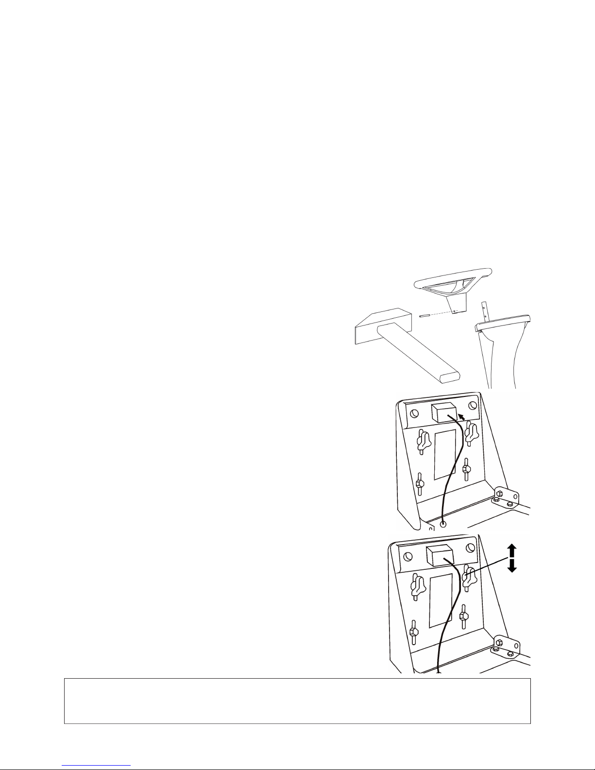
52
4. AUSPACKEN
Der Rasentraktor wird in einer Stoffhülle geliefert. Aus Gründen des Transportes sind bestimmte Baugruppen demontiert und
werden erst vor Inbetriebnahme montiert. Das Auspacken des Gerätes und die Inbetriebnahme erfolgt beim Verkäufer im Rahmen
der Serviceinspektionen.
4.1 KONTROLLE NACH DEM AUSPACKEN
Nach Abnahme der Transporthülle nehmen Sie den Traktor von der Palette. Kontrollieren Sie das Gerät, ob es durch den Transport
nicht beschädigt wurde. Packen Sie alle Baugruppen aus und kontrollieren Sie sie.
In der Grundausstattung werden geliefert:
• Mähwerk
• Lenkrad
• Sitz
• Dokumentation (Packschein, Bedienungsanleitungen für Mähwerk,Motor und Batterie, Serviceheft )
4.1.1 ENTSORGUNG DER VERPACKUNG
Nach dem Auspacken ist es nötig,die Verpackung zu Entsorgen. Die Entsorgung führen Sie nach den gültigen Vorschriften durch.
Trennen Sie bei der Entsorgung das Verpackungsmaterial entsprechend. Sie können die Entsorgung durch eine entsprechende
Firma durchführen lassen.
4.2 VORBEREITUNG AUF DIE INBETRIEBNAHME
In Anbetracht des technischen Charakters dieser Arbeit, wird diese Tätigkeit durch Ihren Verkäufer durchgeführt (nach Angaben
des Herstellers).
4.2.1 MONTAGE DES LENKRADES
Stellen Sie den Rasentraktor auf eine ebene Fläche und stellen Sie die Vorderräder
gerade.
Setzen Sie das Lenkrad in der gewünschten Höhe auf die Lenksäule und sichern
Sie es mit dem mitgelieferten Splint.
4.2.2 MONTAGE DES SITZES
Nehmen Sie die Verpackungshülle des Sitzes ab. Setzen Sie den Sitz an die Stelle
am Traktor ,die dafür vorgesehen ist und befestigen Sie ihn mit den vorgesehenen
Schrauben.
4.2.3 SITZEINSTELLUNG
Die Einstellung des Sitzes ist folgendermaßen vorzunehmen:
Lösen Sie die Kopfschrauben. Schieben Sie den Sitz vor oder zurück in die gewünschte
Lage. Ziehen Sie die Schrauben wieder an.
4.2.4 ANSCHLUSS DER BATTERIE
Beim Anschluss der Batterie verfahren Sie nach der Bedienungsanleitung. Die Batterie
ist an der rechten Sitzseite unter der Motorhaube.Lösen Sie die Schrauben an den
Polen der Batterie. Das rote Kabel verbinden Sie mit dem “+” Pol der Batterie . Das
braune Kabel mit dem “–” Pol der Batterie.
ACHTUNG!!!
Ein falscher Anschluss der Batterie kann zur Beschädigung des Gerätes führen.
Beim Abklemmen der Batterie immer erst den Minuspol lösen.
Halten Sie die Anweisung in der Bedienungsanleitung für die Batterie ein.
Page 55
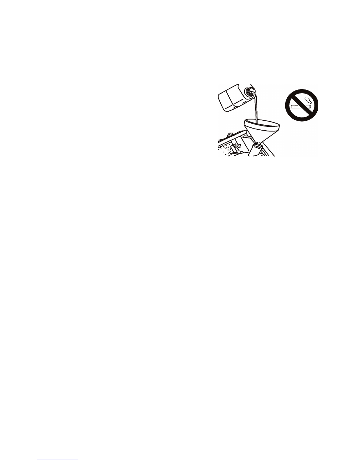
53
5. INBETRIEBNAHME
In Anbetracht des technischen Charakters dieser Arbeit,wird diese Tätigkeit durch Ihren Verkäufer durchgeführt (nach Angaben
des Herstellers).
5.1 KONTROLLE DES ÖLSTANDES DES MOTORS
Verfahren Sie nach der Bedienungsanleitung für den Motor, achten Sie auf die Hinweise im Kap. 7.1 “Übersicht über Kontrollen
und Wartungen“.
5.2 KONTROLLE DER BATTERIE
Verfahren Sie nach der Bedienungsanleitung.
5.3 FÜLLEN DES BENZINTANKS
• Das Gerät ist aus Sicherheitsgründen ohne Treibstoff transportiert wurden.
• Das Einfüllen von Treibstoff nur im geparktem und kaltem Zustand.
• Benutzen Sie nur bleifreies Benzín (Natural 95).
• Der Tank befi ndet sich unter dem Sitz und ist leicht durch das Klappen des
Sitzes nach vorn erreichbar.
• Den Tankdeckel langsam öffnen, da sich Überdruck aufgebaut haben kann.
• Zum Einfüllen benutzen Sie einen Kanister und vermeiden Sie den Tank zu
überfüllen.
• Die Füllhöhe können Sie am Ausschnitt an der linken Sitzseite sehen.
• Übergelaufenes Benzin sofort abwischen. Säubern Sie den Tank regelmäßig
da es sonst zu Verunreinigungen kommen kann.
• Vermeiden Sie beim Auffüllen des Treibstoffes den Umgang mit offenem
Feuer bzw. rauchen Sie nicht.
Page 56
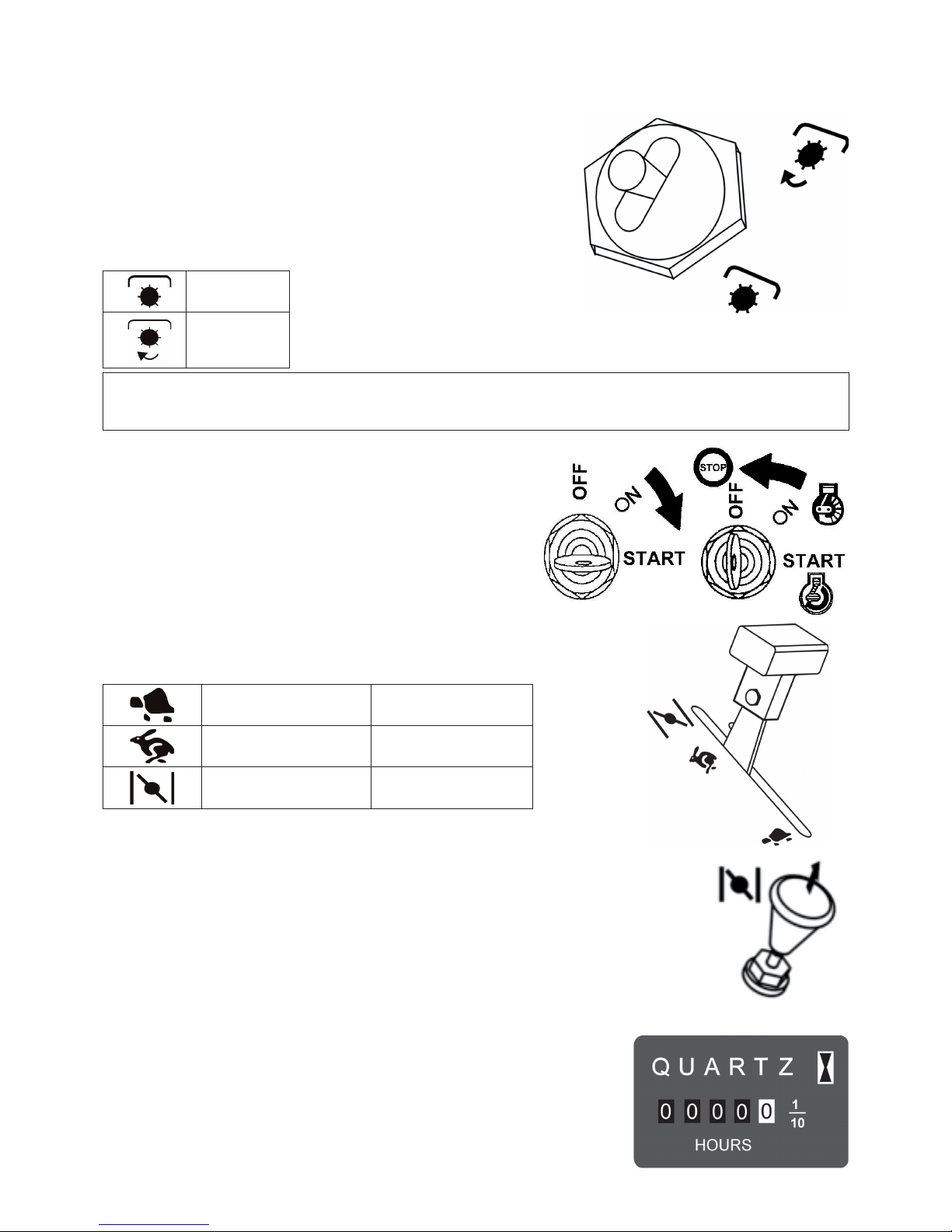
54
6. BEDIENUNG
6.1 BESCHREIBUNG UND FUNKTION DER
BEDIENTEILE
6.1.1 DER SCHALTER DES MÄHWERKES
Der Schalter des Mähwerkes schliesst die elektromagn. Kupplung, welche den
Antrieb vom Motor per Riementrieb auf das Mähwerk überträgt. Der Schalter ist
in der Lage “AUS” gegen Benutzung gesichert. Zum Einschalten ist es nötig den
Umklappschalter herauszuziehen und in die Lage „Eingeschaltet“ zu bewegen.
EIN
AUS
ACHTUNG!!!
Wenn das Mähwerk in der Transportposition ist (siehe Kap. 6.1.6), kann es nicht gestartet werden.
Die Transportstellung ist durch einen Sicherheitsschalter gesichert.
6.1.2 ZÜNDSCHLOSS
Der Schlüssel hat drei verschiedene Positionen.
OFF - Zündung aus
ON - Zündung ein
START - Anlassen des Motors
6.1.3 GASPEDAL
Reguliert die Motordrehzahl in den verschiedenen Positionen:
(Bild 6.1.3)
MIN Leerlauf des Motors
MAX
Maximale Umdrehung
des Motors
KALTSTARTANLAGE * Kaltstart des Motors
* Der Kaltstarter ist in Abhängigkeit mit dem Motortyp installiert.
6.1.4 KALTSTARTANLAGE
Kaltstart des Motors Der Kaltstarter ist in Abhängigkeit mit dem Motortyp installiert.
6.1.5 MOTORSTUNDENZÄHLER
Der Motorstundenzähler ist in Abhängigkeit vom Gerätetyp installiert. Ist nur bei
eingeschalteter Zündung und Sitzschalter (eingeschaltet durch das Gewicht des Fahrers)
in Betrieb.
Manipulationen mit dem Motorstundenzähler bedeutet Garantieverlust. Bei Störungen
informieren Sie Ihren Service.
Page 57
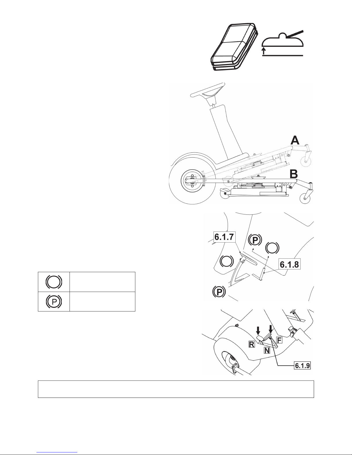
55
6.1.6 SCHALTER ZUM ANHEBEN DES MÄHWERKES
Dieser Schalter dient zum Anheben des Mähwerkes in die Transportstellung
bzw. in die Arbeitslage mit dem Hebel 6.1.11.
Lagen des Mähwerkes sind: A - Transportstellung
B - Arbeitsstellung
Zum Heben oder Senken halten Sie den Schalter
gedrückt.
Bei Erreichen der Endstellung lassen Sie den Schalter
los.
Auch wenn Sicherheitskontakte vorhanden sind, kann es
bei weitergedrücktem Schalter zu Störungen der Elektrik
kommen.
6.1.7 BREMSE
Wenn das Pedal gedrückt wird, wird das Mähwerk gebremst. Benutzen Sie
niemals Bremse und Fahrpedal gleichzeitig - es kann zur Beschädigung
des Getriebes kommen.
6.1.8 HANDBREMSHEBEL
Die Handbremse hat 2 Stellungen. Vor dem Stellen des Hebels in die
Position “P” treten Sie das Bremspedal. Durch das erneute Treten des
Bremspedals wird die Handbremse erneut gelöst.
UNGEBREMST
GEBREMST
6.1.9 FAHRPEDAL
Bestimmt den Antrieb der Hinterräder und reguliert die Geschwindigkeit
in beide Richtungen.
Antrieb vorwärts Treten Sie langsam das Fahrpedal in Richtung “F“,
mit einem weiteren Durchtreten erhöhen Sie die Geschwindigkeit und
umgekehrt.
Antrieb rückwärts
Treten Sie langsam das Fahrpedal in Richtung “R“, mit einem weiteren
Durchtreten erhöhen Sie die Geschwindigkeit und umgekehrt.
Wenn Sie das Pedal freigeben, kehrt es automatisch indie Stellung “N“
(Neutrál) zurück und das Gerät bleibt stehen.
ACHTUNG!!!
Ein Richtungswechsel ist erst nach dem Anhalten des Gerätes möglich.
Page 58
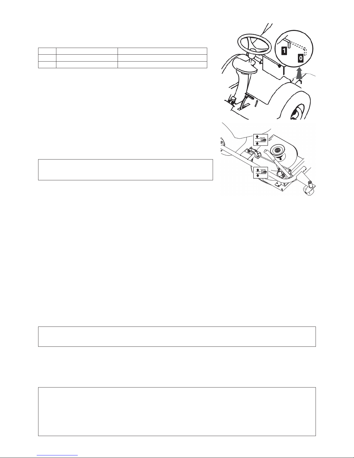
56
6.1.10 BY-PASS
Der Hebel dient dem Ausschalten des Vorderradantriebes.
Er hat 2 Stellungen:
Lage Antrieb der Vorderräder Benutzung
0
AUS Schieben des Gerätes, Motor ist aus
1
EIN Fahrt, Motor läuft
6.1.11 HEBEL ZUR EINSTELLUNG DER MÄHHÖHE
Dient zur Einstellung der Schnitthöhe des Rasens. Er hat 8 Arbeitspositionen,
welcher einer Mähhöhe von 3 bis 8 cm entsprechen. Umso höher die Arbeitsposition
ist, umso höher bleibt der Rasen.
ACHTUNG!!!
Bei Betrieb ohne Mähen muss das Mähwerk mit dem Schalter 6.1.6 in die
Transportstellung gebracht werden.
6.2 BETRIEB UND BEDIENUNG
Sicherheitsschutz des Gerätes
Das Mähwerk ist mit Sicherheitskontakten ausgerüstet, die über einen Schalter unter dem Sitz reguliert werden. Der Motor
wird automatisch abgestellt, sobald der Fahrer den Sitz verlässt. Der Motor kann nur gestartet werden, wenn der Schalter des
Mähwerkes in der Stellung “AUS” steht und das Mähwerk in der Transportstellung steht und nicht das Fahrpedal getreten ist.
6.2.1 ANLASSEN DES MOTORS
• Kontrollieren Sie ob sich genug Treibstoff im Tank befi ndet.
• Setzen Sie sich bequem auf den Sitz und heben Sie mit dem Schalter das Mähwerk 6.1.6 in die Transportstellung.
• Den Schalter zum Einschalten des Mähwerkes 6.1.1. stellen Sie in die Position „AUS“.
• Achtung, treten Sie nicht auf das Fahrpedal 6.1.9.
• Gashebel 6.1.3 stellen Sie in die Position „MAX“.
• Ziehen Sie den Kaltstarter heraus 6.1.4.
• Manipulieren Sie nicht mit dem Mähwerkhebel 6.1.11.
• Drehen Sie den Schlüssel in die Position 6.1.2 „START“. Die Zeit des Anlassens darf 10 Sekunden nicht überschreiten
– ansonsten droht die Beschädigung des Batterieschalters.
• Sobald der Motor läuft ,lassen Sie den Zündschlüssel los. Der Schlüssel kehrt automatisch in die Lage „ON“ zurück.
• Nehmen Sie den Kaltstarter langsam zurück 6.1.4.
• Den Gashebel langsam in die Lage „MIN“ des Leerlaufs bewegen 6.1.3 (Sie verringern die Motordrehzahl).
• Lassen Sie den Motor vor dem Einsatz des Mähwerkes ein paar Minuten laufen.
GEFAHR !
Lassen Sie den gestarteten Motor nicht in geschlossenene Räumen laufen.
Auspuffgase sind sehr gefährlich. Hände, Beine, Bekleidung von Auspuff und beweglichen Teilen fernhalten.
6.2.2 ABSTELLEN DES MOTORS
• Den Gashebel 6.1.3 in die Pos. „MIN“ bewegen.
• Schalten Sie das Mähwerk mit dem Schalter 6.1.1 ( Siehe Kap. 6.2.4)aus.
• Wenn der Motor überhitzt ist,lassen Sie ihn eine Weile im Leerlauf laufen.
• Schalten Sie den Motor durch Drehen des Zündschlüssels 6.1.2.in die Lage „STOP“ aus und nehmen Sie den Schlüssel aus
dem Zündschloss.
ACHTUNG!!!
Stellen Sie niemals den Motor durch Verlassen des Sitzes ab und das Sie den Zündschlüssel trotzdem in der Lage „ON“
lassen, es kann zu Schäden an der Elektrik kommen. Drehen Sie dazu den Zündschlüssel immer in die Lage „OFF“
und nehmen Sie ihn aus dem Zündschloss.
WICHTIG !!
Vor dem Ausschalten verringern Sie die Motordrehzahl auf Leerlaufniveau,anderenfalls kann es zu Selbstzündungen
kommen,die Auspuff und Motor beschädigen können.
Page 59

57
6.2.3 EIN-UND AUSSCHALTEN DES MOTORS
a) Einschalten
• Gashebel 6.1.3 stellen Sie in die Position „MAX“.
• Lassen Sie das Mähwerk mit dem Mähwerkschalter in die Arbeitsposition 6.1.6 , eingestellt mit dem Hebel 6.1.11, anderenfalls
kann es zur Beschädigung des Riemenantriebes kommen.
• Stellen Sie den Schalter für das Mähwerk 6.1.1 in die Stellung „EIN“.
Das Mähwerk wird nur eingeschaltet, wenn der Bediener auf dem Sitz sitzt
b) Ausstellen
• Stellen Sie den Schalter für das Mähwerk 6.1.1 in die Stellung „AUS“.
• Verlässt der Fahrer den Sitz, wird automatisch der Motor ausgeschaltet und damit auch das Mähwerk.
ACHTUNG!!!
Schalten Sie niemals das Mähwerk aus, indem Sie vom Sitz steigen. Wenn Sie den Zündschlüssel nicht von “ON” auf “OFF”
(STOP) stellen, ist ein Teil der Elektrik weiterhin unter Spannung und es kann zu Schäden kommen.
6.2.4 EINSTELLUNG DER ARBEITSHÖHE
Das Mähwerk muss in die Arbeitshöhe „B“ gelassen werden (siehe Bild in Kap. 6.1.6) durch umschalten des Schalters in die
Position 6.1.6 „Ablassen“.
Den Mähwerkhebel 6.1.11 stellen Sie in Richtung nach oben, wenn Sie das Mähwerk höher einstellen möchten, oder Sie drücken
ihn nach unten, wenn das Mähwerk näher zum Erdboden mähen soll.
Stellung „1“ benutzt man, um Unebenheiten des Geländes zu kopieren. Benutzen Sie diese Stellung nicht dauerhaft, weil es sonst
zu einer verstärkten Abnutzung des Mähwerkes kommen kann.
Das Mähwerk ist mit drei Rädern ausgestattet, welche im falle von Unebenheiten des Erdbodens als Schutz vor Beschädigung
der Mähmesser dienen.
6.3 FAHREN
Vor Fahrtantritt überzeugen Sie sich durch treten des Bremspedals davon,das die Handbremse gelöst ist. 6.1.7. Der Handbremshebel
6.1.8 darf nicht in der Position „P“ bleiben!
Der By-pass Hebel 6.1.10 muss in der Position “1”sein, d.h. der Fahrhebel muss eingeschaltet sein.
Bei der Überführung zum Mähort, muss das Mähwerk ausgeschaltet sein (Schalter 6.1.1) und sich in der Transportstellung
befi nden. Schalter 6.1.6 in der Position „Anheben“.
Beim Hindernissen die höher als 8 cm (Bordsteine usw..) sind, sollten Auffahrten benutzt werden, damit das Mähwerk und das
Getriebe nicht beschädigt werden.
Die eigentliche Fahrt führen Sie folgendermaßen durch:
• Den Gashebel in die Lage des Leerlaufs bewegen 6.1.3 Sie verringern die Motordrehzahl auf „MIN“.
• Beim Anfahren langsam das Fahrpedal in die gewünschte Richtung treten 6.1.9 - bei einem schnellen Durchtreten kann es
zu Unfällen kommen.
• Ein Richtungswechsel vorwärts - rückwärts ist nur nach dem Anhalten des Gerätes möglich. Wenn das Gerät nicht steht, kann
es zu einem Getriebeschaden kommen.
• Benutzen Sie niemals Fahrpedal und Bremspedal gleichzeitig, es kann zu Getriebeschäden kommen.
ACHTUNG!!!
Ein Anhalten ist nur durch nur Loslassen des Fahrpedals und dem Treten des Bremspedals möglich. Beim Treten des
Bremspedals geht das Fahrpedal automatisch in die Position „N“. Der Bremsweg ist dabei kürzer als 2m.
6.4 GESCHWINDIGKEIT DER FAHRT UND DAS RASENMÄHEN
Gashebel 6.1.3 stellen Sie in die Position „MAX. Stellen Sie die Höhe des Mähwerkes 6.1.11 ein(siehe Kap. 6.2.4).
Allgemein gilt, um so feuchter , höher und dichter der Rasen, um so niedriger sollte die Geschwindigkeit sein. Ist die Geschwindigkeit
oder die Belastung zu gross ,sinkt die Drehzahl der Messer und es verschlechtert sich die Qualität des Mähens.
Wenn der Rasen sehr hoch ist, sollte mehrmals gemäht werden. Die erste Mähung in der maximalen Höhe, gegebenenfalls mit
verringerter Mähbreite und danach in der gewünschten Höhe.
Wir empfehlen das Mähen in Längsrichtung oder kreuzweise. Die Überlappung des letzten Mähganges erhöht die Wirkung der
Messer und verbessert die Ansicht des Rasens.
Bei der Fahrt auf unebenen Terrain kann es zu Schwankungen der Geschwindigkeit kommen.
Wir empfehlen deshalb folgende Geschwindigkeiten:
Zustand des Bewuchses Empfohlene
Geschwindigkeit
hoch, dicht und nass 2 - km/h
durchschnittliche Bedingungen 3 - 5 km/h
niedriger und trockener Bewuchs 5 - km/h
Fahrt ohne Mähwerkeinsatz 7 - km/h
6.5 FAHREN AM HANG
Diese Gerät kann an Hängen bis zu einem Steigungswinkel von 14° (25%) arbeiten. Bei Arbeiten am Hang benutzen Sie immer
niedrigere Geschwindigkeiten.
Fahren Sie immer senkrecht zum Hang, also hoch und runter. Die Fahrt längs zum Hang ist untersagt. Vom Hang und
über Hindernisse sollten Sie langsamer fahren. Besondere Aufmerksamkeit verlangt das Lenken und Drehen am Hang. Bei
Abstellen ziehen Sie stets die Handbremse an. Bei Überlastung des Gerätes bei Hängen mit mehr als 14° (25%) Steigungswinkel
kann es zu Beschädigung des Getriebes kommen. Für so entstandene Schäden übernimmt der Hersteller keine Garantie.
Page 60

58
7. WARTUNG DES GERÄTES
7.1 ÜBERSICHT ÜBER KONTROLLEN UND INSTANDHALTUNGEN
Nach der Saison - vor der Einlagerung
Vor der Saison
Alle 100 Stunden
Alle 50 Stunden
Alle 25 Stunden
Monatlich
Nach jeder Benutzung
Nach den ersten 5 Stunden
Nach den ersten 2 Stunden
Vor jeder Benutzung
Kontrolle Ölstand (Getriebe, Motor)
OO
Ölwechsel O O 1,2 O
Wechsel Benzin lters
O
Wartung der Batterie (Kontrolle der Batterie üssigkeit) O O
Einstellung und Kontrolle der Riemen O O 4O O
Kontrolle der Bremsen O O
Kontrolle des Reifendruckes O O
Kontrolle der Elektrik) O O
Säubern des Mähwerkes O O
Kontrolle der Schraubverbindungen O O O
Kontrolle der Funktion der Sicherheitsschalter O
Kontrolle und Einstellung des Motors, Getriebe, der elektromagnetischen
Kupplung
O
Kontrolle und Wartung des Lu lters, der Zündkerzen, gegebenenfalls
Austausch
O 1,2
Kontrolle des Mähwerkes (Spiel, Gleichlauf der Welle, Kontrolle und
Schärfung der Messer)
O O 3
Erklärungen zur Tabelle :
1. Machen Sie öfters Ölwechsel, wenn das Gerät mehr belastet wird und oder die Arbeiten um 35°C oder höher erfolgen.
2. Wenn des Gerät in staubigen Bereichen arbeitet, machen Sie die Kontrollen öfters.
3. Die Kontrolle ist öfters durchzuführen, wenn in einem sandigen Bereich gearbeitet wird.
4. Die Kontrolle ist öfters durchzuführen, wenn die Keilriemen neu sind.
7.2 KONTROLLE DES LUFTDRUCKS
Halten Sie den vorgeschriebenen Reifendruck ein und kontrollieren Sie Ihn regelmässig. Andere Werte können zur Beschädigung
der Reifen bzw. zum Kontrollverlust über das Gerät führen. Die Einhaltung des Reifendruckes ist für ein gleichmässiges Mähen
wichtig.
• Druck in den vorderen Reifen 80 - 140 kPa
• Druck in den hinteren Reifen 80 - 140 kPa
7.3 WARTUNG NACH DER ARBEIT
Nach der Beendigung des Mähens stellen Sie das Mähwerk in die höchste Position und Schalten den Antrieb der Messer ab.
Schalten Sie die Zündung aus, treten Sie das Bremspedal und ziehen Sie die Handbremse.
7.3.1 SÄUBERN
Nach jeder Benutzung des Mähwerkes entfernen Sie alle Rückstände .
ACHTUNG!!!
Vor dem Beginn der Reinigung, des Waschens oder der Reparatur ziehen Sie den Zündschlüssel ab. Arbeiten Sie immer mit
Arbeitshandschuhen, festem Schuhwerk und Arbeitskleidung. Achten Sie darauf, das kein Benzin oder Öl verschüttet wird.
7.3.2 WASCHEN
Achten Sie darauf, das kein Wasser in die Elektrik, die Batterie usw. gelangt. Benutzen Sie keine Hochdruckreiniger.
Das Waschen erfolgt folgendermaßen:
• Das Waschen sollte auf einer ebenen Fläche erfolgen.
• Säubern der Kunststoffteile mittels Schwamm und Reinigungsmittel.
• Demontieren Sie Zapfen 2 und 3 (siehe Bild in Kapitel 7.13).
• Heben Sie das Mähwerk in eine senkrechte Position. Mittels einer Bürste und Wasser die Rasenreste aus dem Mähwerk
entfernen.
Page 61
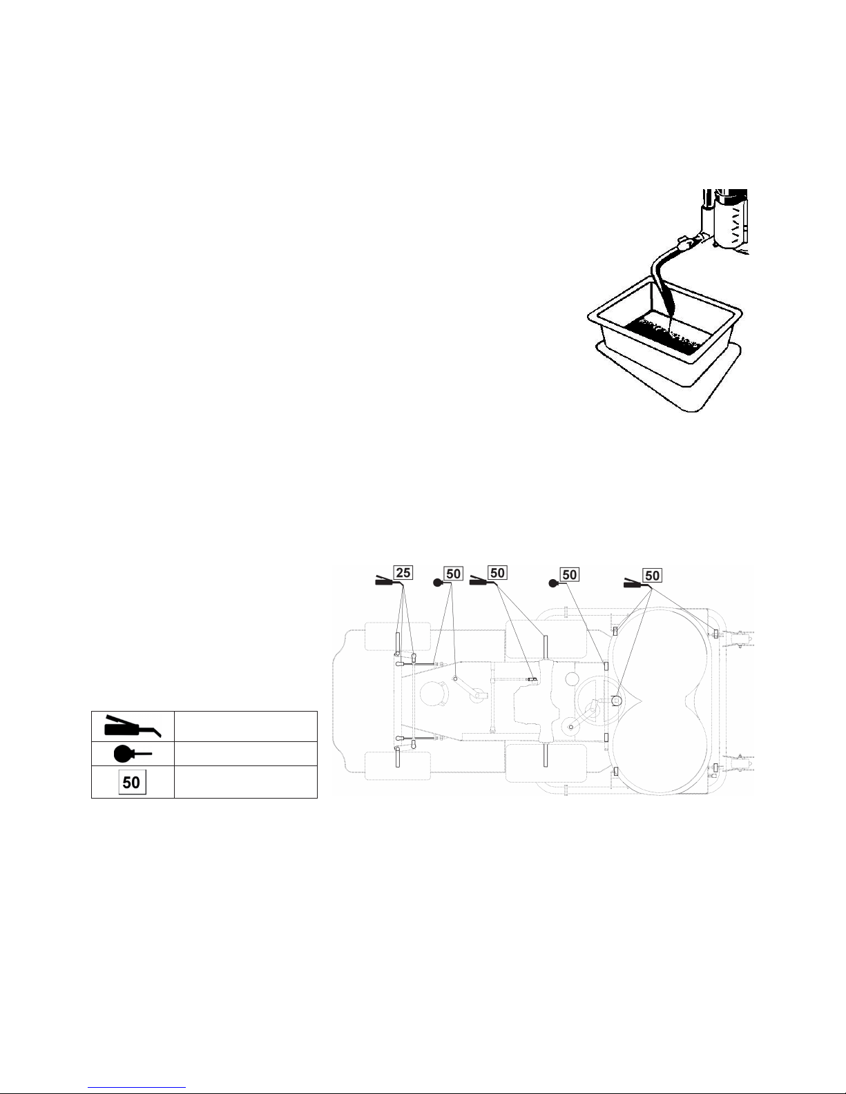
59
7.4 INSTANDHALTUNG DER BATTERIE
Die Wartung der Batterie führen Sie nach den Anweisungen in der Betriebsanleitung zur Batterie durch.
7.5 MOTORINSTANDHALTUNG
Die Wartung des Motors führen Sie nach den Anweisungen in der Betriebsanweisung zum Motor durch.
7.5.1 KONTROLLE DES ÖLSTANDES DES MOTORS
Die Kontrolle des Ölstandes führen Sie nach den Anweisungen der Betriebsanleitung für den
Motor durch.
7.5.2 ÖLWECHSEL
Der Motor hat eine Ölablassschraube.
• Legen Sie unter den Motor ein Gefäss mit mindestens 2 l Inhalt und lassen Sie das Öl ab.
• Schrauben Sie die Ölablassschraube heraus und schrauben Sie den Deckel des
Öleinlassstutzens ab, damit das alte Öl besser ablaufen kann.
• Schraube Sie die Ölablassschraube wieder ein ,füllen Sie die richtige Menge des richtigen
Öles ein(siehe Bedienungsanleitung zum Motor) und schrauben Sie den Öldeckel auf.
• Das Altöl entsorgen Sie an den dafür vorgesehenen Stellen.
7.5.3 AUSTAUSCH DES BENZINFILTERS
Den Austausch des Kraftstofffi lters führen Sie nach den Anweisungen der Betriebsanleitung für den Motor durch.
7.5.4 WARTUNG DES LUFTFILTERS
Die Wartung des Luftfi lters führen Sie nach den Anweisungen in der Betriebsanweisung zum Motor durch.
7.5.5 INSTANDHALTUNG DER ZÜNDKERZEN
Die Wartung der Zündkerzen führen Sie nach den Anweisungen in der Betriebsanweisung zum Motor durch.
7.6 SCHMIERUNG
Die Schmierung führen Sie nach dem
Schmierplan durch, Kontrolle der Funktion
incl. Wartung nach der Übersicht in Kapitel.
7.1.
Die Lager der Spannrollen, der Führungsrollen und die Lager des Mähwerkes sind
selbstschmierend.
Vor der Einlagerung schmieren Sie gründlich
alle Stellen, die eine Schmierung erfordern.
Plastisches Schmiermittel
Öl SAE 30
Interval in Stunden
Mit pastischem Schmiermittel ist zu schmieren:
• die Achszapfen
• Kippgelenke der Verbindungszüge - demontieren, schmieren
• Kippgelenke der Räder - demontieren, schmieren
• Schraube des Bremsseils - schmieren in der Nähe der Schraubenöffnung
• Schraube des Mähwerkzuges - schmieren in der Nähe der Schraubenöffnung
• Kippgelenke der Verbindungszüge der Lenkung - demontieren, schmieren
• Lager der Hinterräder
• Achslagerung
• Gelenk der Vorderachse - über eine Fettpresse
• Lenkstocklagerung - schmieren
• Spannmechanismus - demontieren und schmieren
Mit Öl ist zu schmieren:
• Lenkseil
• Zapfen der Mähwerklagerung
• Drehpunkte der Fahrpedalen
• Drehpunkte des Bremspedals
Page 62
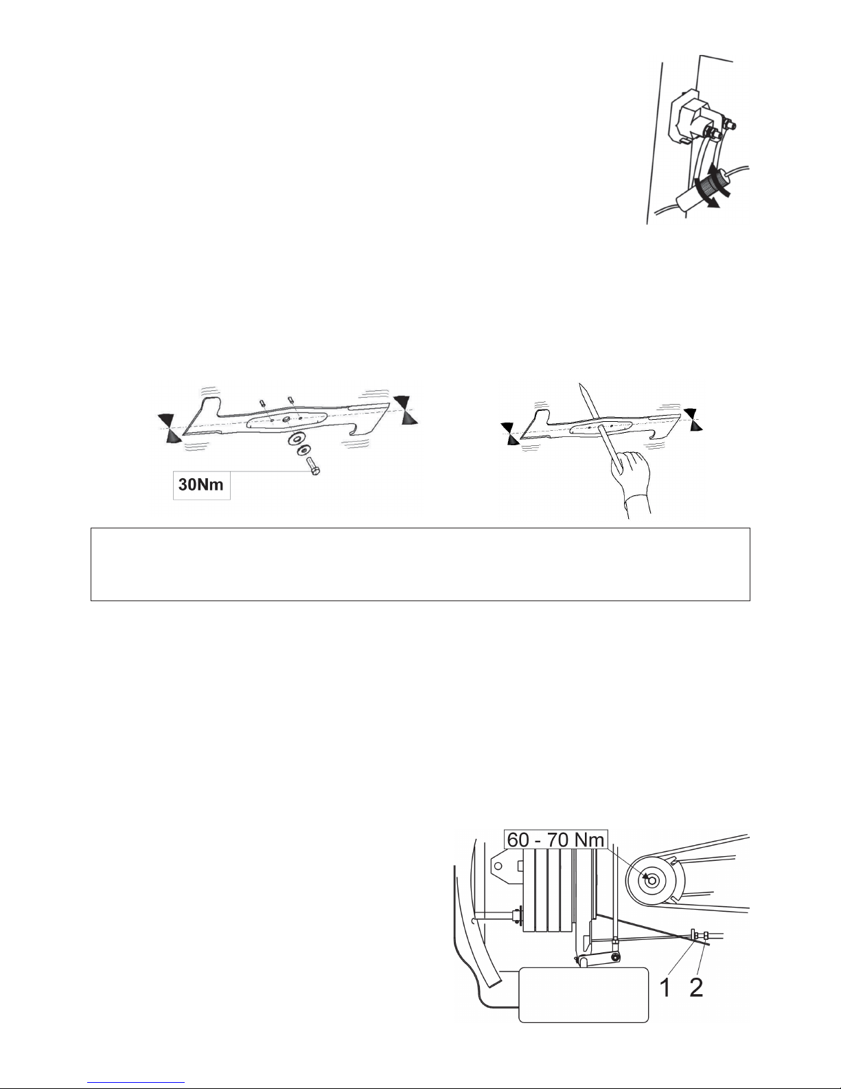
60
7.7 AUSTAUSCH DER SICHERUNGEN
Öffnen Sie die vordere Haube. Schrauben Sie die Hülle auf, wechseln Sie die Sicherungen durch Sicherung
der gleichen Stärke, z.B.20 A.
Wenn Sich der Motor auch nach dem Wechsel nicht starten lässt, kontaktieren Sie Ihren Service.
7.8 ANHEBEN DES GERÄTES
Wenn Sie das Mähwerk anheben möchten benutzen Sie Heber und Stützen.
Gehen Sie folgendermaßen vor:
• Geben Sie den Heber unter das Getriebe und heben Sie den vorderen Teil des Gerätes an.
• Geben Sie zwei Stützen unter die Enden der hinteren Achse zwischen den beiden Rädern.
• Heben Sie den vorderen Teil an und geben Sie zwei Stützen unter die Zapfen der Vorderräder.
7.9 AUSTAUSCH DER MESSER DES MÄHWERKES
Die Mähmesser müssen scharf sein, statisch ausgewogen und gleichmässig. Diese Bedingungen sind für eine gleichmässige
Rasenhöhe und Mähqualität sehr wichtig. Stumpfe Messer verschlechtern die Mähqualität, wie auch den Einsammeleffekt des
gemähten Rasens.
ACHTUNG!!!
Sollte es dazu kommen, dass die Messer beim Mähen auf einen festen Gegenstand treffen, halten Sie an und
kontrollieren Sie die Messer! Es kann zur Beschädigung oder Abtrennung der Messerbolzen kommen.
Ersetzen Sie sie durch mitgelieferte neue Bolzen.
Kontrollieren Sie auch, ob die Befestigungsschrauben mit dem entsprechenden Moment angezogen sind.
Den Wechsel der Messer nehmen Sie folgendermaßen vor:
• Heben Sie das Mähwerk in die Transportposition.
• Schrauben Sie beide Messer ab, säubern und schärfen Sie sie . Kontrollieren Sie die statische Ausgewogenheit der Messer (siehe
Bild oben).
• Bei der Montage achten Sie darauf, dass die Ausbuchtung der Messer nach oben in das Mähwerk zeigen. Vertauschen Sie
nicht das linke Messer mit dem rechten.
Am rechten Messer hat die Schraube ein Linksgewinde.
• Kontrollieren Sie die Haltebolzen, welche als Schutz des Mähwerkes gegen Beschädigung dienen. Sind diese Bolzen
beschädigt, wechseln Sie sie sofort aus.
• Die Befestigungsschrauben ziehen Sie sorgfältig mit dem vorgeschrieben Moment von 30±3 Nm an.
7.9.1 SCHÄRFEN DER MESSER
Die Messer können mit der Feile oder dem Schleifstein geschärft werden. Führen Sie die Schärfung nicht an angebauten Messern durch.
Grosse Sorgfalt widmen Sie dem Ausgleich und dem Auswiegen der Messer. Nicht ausgewogene Messer können durch ihre
Vibrationen den Motor oder das Mähwerk beschädigen.
Beim Auswiegen geben Sie einen Schraubenzieher in die
Zentrierungslöcher und bringen Sie die Messer in eine waagerechte
Stellung (siehe Bild 7.9). Wenn das Messer in dieser Lage bleibt , ist
es ausgewogen. Wenn einer der Messerenden überwiegt, schleifen
Sie es weiter ab, bis eine Ausgewogenheit erreicht ist
Die zulässige statische Unausgewogenheit darf max. 2g betragen.
7.10 WARTUNG DER LENKUNG
Kontrollieren Sie regelmässig das Lenkungsspiel. Im Falle eines
zu grossen Spiels wieder einstellen. Bei der Einstellung zuerst die
Räder gerade stellen. Lösen Sie Mutter 1 und durch Drehen der
Einstellschraube 2 am Ende des Zug begrenzen Sie das Spiel der
Kette auf ein Minimum. Danach Mutter 1 fest anziehen. Führen Sie
dies auch am anderen Ende der Kette durch. Achten Sie darauf, dass
beide Züge an den Enden der Kette gleich angezogen sind.
Page 63
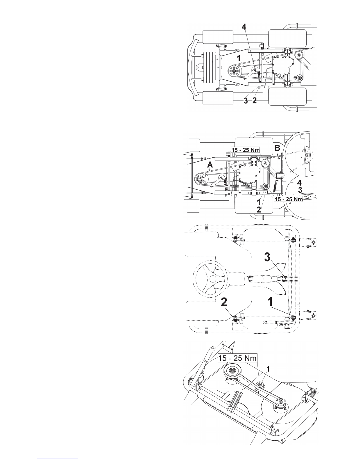
61
7.11 KONTROLLE UND EINSTELLUNG
DES RIEMENANTRIEBS DES
ANTRIEBES
Riemen 1 ist richtig gespannt, wenn bei einer Krafteinwirkung
von 4kp auf den Riemen zu einer Durchbiegung von ca. 1,5 cm
kommt. Die Einstellung der Riemenspannung führen Sie durch das
Drehen der Mutter 3 auf der Schraube 2 der Spannfeder durch.
7.12 KONTROLLE UND EINSTELLUNG
DES RIEMENANTRIEBES DES
MÄHWERKES
Keilriemen A:
Riemen ist richtig gespannt, wenn bei einer Krafteinwirkung
von 4kp auf den Riemen zu einer Durchbiegung von ca. 1,5 cm
kommt. Die Einstellung der Riemenspannung führen Sie durch
das Verschieben des Riemens 2 , nach dem Lösen der Mutter 1
durch. Nach der Einstellung ziehen Sie die Mutter 1 wieder an.
Keilriemen B:
Der >Riemenantrieb des Mähwerkes wird über eine Rolle mit
Feder gespannt. Bei einer Verringerung der Riemenspannung
aufgrund der Belastung vergössern Sie die Spannung durch das
Umhängen der Feder 3 in die zweite Öffnung des Rahmens 4 der
Spannrolle.
7.13 HERAUSNEHMEN DES
MÄHWERKES AUS DEM
TRAKTOR
• Lassen Sie das Mähwerk mit dem Schalter in eine
Arbeitsposition 6.1.6. Nach Erreichen dieser, den Schalter
loslassen.
• Durch Verschieben des Hebels der Riemenspannung 4 (Bild
7.12) lösen Sie den Keilriemen und nehmen Sie ihn heraus.
• Nehmen Sie die Spannfeder 3 (Bild 7.12) aus dem Rahmen
der Spannrolle.
• Nehmen Sie die beweglichen Abdeckungen von den vorderen
Bolzen 2 und auch von den hinteren Bolzen 1 der Aufhängung
des Mähwerkes.
• Demontieren Sie den Bolzen 3 und die Schraube zum Heben
des Mähwerkes.
• Ziehen Sie mit Hilfe einer Zange beide hinteren Bolzen 1 der
Aufhängung des Mähwerkes heraus.
Bei der Herausnahme darauf achten, dass es nicht zu
Verletzungen der Hand oder der Finger kommt.
• Nehmen Sie die vorderen Bolzen 2 der Aufhängung heraus .
• Nehmen Sie das Mähwerk langsam heraus.
7.14 EINSTELLUNG DES
ZAHNRIEMENS DES
MESSERANTRIEBES
• Lassen Sie das Mähwerk per Schalter in eine Arbeitsposition
6.1.6.
Nach Erreichen dieser Position sofort den Schalter loslassen.
• Demontieren Sie die Abdeckung des Zahnriemens.
• Lösen Sie die Mutter 1 und spannen Sie den Riemen durch
Verschiebung des Riementriebs.
• Kontrollieren Sie die Spannung. Riemen ist richtig gespannt,
wenn bei einer Krafteinwirkung von 4kp auf den Riemen zu
einer Durchbiegung von ca. 0,5 cm kommt.
• Ziehen Sie die Mutter 1 wieder an und montieren Sie die
Abdeckung auf den Zahnriemen.
Page 64
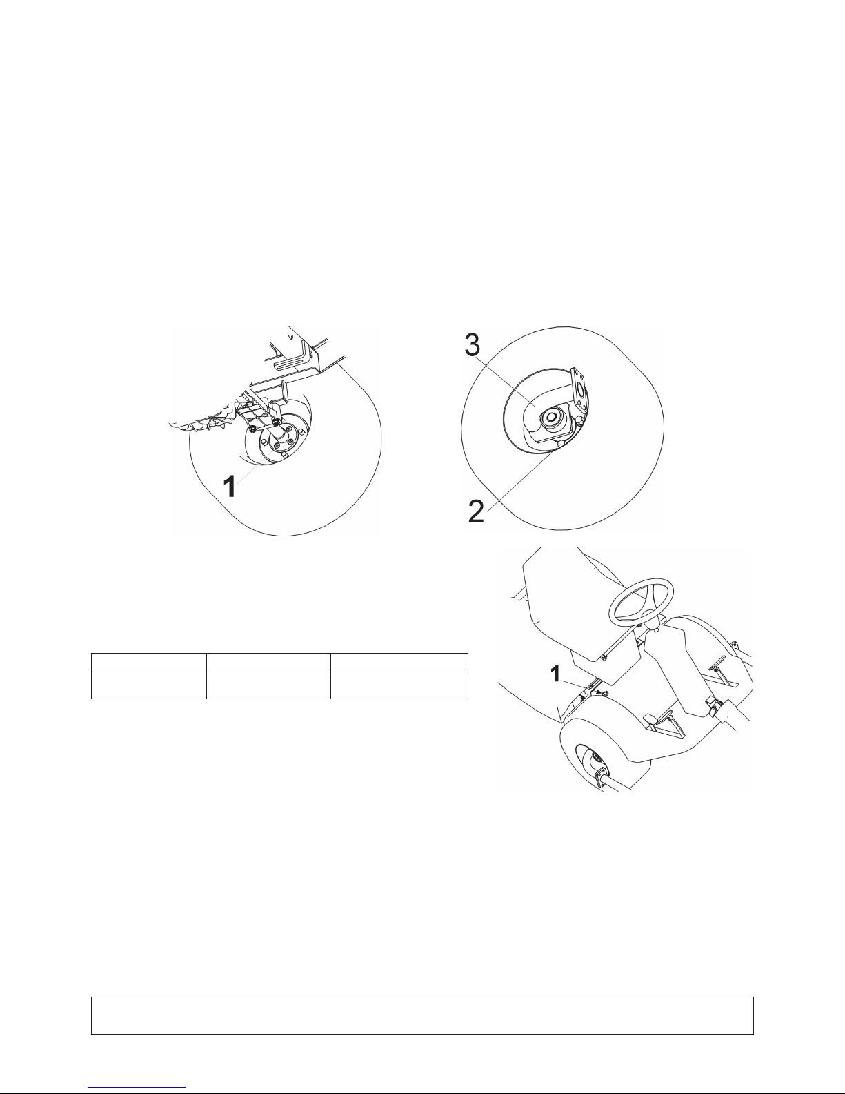
62
7.15 WECHSEL DER RIEMEN
Es handelt sich um eine schwierige Arbeit, die Sie am besten einem autorisierten Service überlassen.
7.16 RADWECHSEL
• Vor dem Wechsel der Räder stellen Sie den Motor ab und ziehen Sie den Zündschlüssel aus dem Zündschloss.
• Stellen Sie das Gerät auf Stützen , wie im Kapitel 7.8. aufgeführt.
• Lassen Sie das Mähwerk mit dem Schalter in eine Arbeitsposition 6.1.6. Nach Erreichen dieser, den Schalter loslassen.
• Beim Wechsel der Vorderräder nehmen Sie das Mähwerk aus dem Gerät (siehe kap. 7.13) und lösen Sie den vorderen Rahmen
des Mähwerkes.
• Durch Ziehen des Spannhebels der Riemen 4 lösen Sie den Keilriemen B (Bild. 7.12) und nehmen Sie ihn heraus.
• An der Innenseite des Rades schrauben Sie die 4 Schrauben 1 heraus, demontieren Sie den Sicherungsring und nehmen Sie
den Halter des Vorderrahmens 3 heraus .
• Schrauben Sie die vier Schrauben 2 und nehmen Sie das Rad ab.
• Beim Wechseln der Hinterräder nehmen Sie die Radabdeckungen ab, demontieren Sie den Sicherungsring, Unterlegscheibe
und nehmen Sie das Rad von der Welle.
Beim Anschrauben der Vorder- oder Hinterräder ist die umgekehrte Reihenfolge zu benutzen.
Vor dem Anschrauben säubern Sie die Räder und schmieren Sie die Aufl agefl ächen leicht mit einem plastischen Schmiermittel.
7.17 WARTUNG DES GETRIEBES
Für eine verlässliche Funktion des Getriebes, ist es notwendig den Ölstand
des Getriebeöls in der richtigen Höhe zu halten. Die vorgeschriebenen Werte
sind in der Tabelle unten aufgeführt. Die Füllöffnung befi ndet sich in Sitznähe
(siehe Bild). Bei Problemen mit dem Getriebe suchen Sie eine autorisierte
Servicestation auf, andererseits kann es zu Schäden am Getriebe kommen.
Getriebetyp Spezifi kation des Öls Ölstand
TUFF-TORQ K46 SAE 10W-30,
API CD
min. in der Hälfte des
Ausgleichbehälters
7.18 EINSTELLUNG DER BREMSEN
Sollten die Bremsen ihre Funktion verlieren, lassen Sie sie durch einen autorisierten Service einstellen oder tauschen.
7.19 ÜBERSICHT DER ANZUGSMOMENTE DER
SCHRAUBENVERBINDUNGEN
Mähwerk: Kapitel:
Mittlere Schraube der Messer 30 ± 3 Nm 7.9
Mutter M12 der Antriebsrolle des Mähwerkes 45 - 55 Nm 7.14
Schraube M8x20 des Rahmens der Spannrolle des Mähwerkantriebes 25 - 35 Nm 14
Motor:
Schraube der elektromagnetischen Kupplung 60 - 70 Nm 7.10
Schraube des Halters der Spannrolle des Antriebes … 25 – 35 Nm 7.10 (Pos. 4)
ACHTUNG!!!
Bei der Demontage und Montage der selbstsichernden Muttern sind jeweils neue Muttern zu verwenden.
Page 65

63
8. BESEITIGUNG VON FEHLERN UND STÖRUNGEN
Führen Sie keine Reparaturen bzw. Wartungen durch, wenn Ihnen die nötige technische Ausrüstung und Qualifi kation
fehlt. Unten aufgeführte Operationen können vom Bediener ausgeführt werden. Werden Reparaturen durchgeführt, die
hier nicht aufgeführt sind, erlischt die Garantie.
Der Hersteller kommt nicht für Schäden auf, die in Folge nicht qualifi ziert durchgeführter Reparaturen, auftreten.
Störung, Fehler Beseitigung
Das Mähwerk mäht
ungleichmässig.
Entfernen Sie Rasenreste aus dem Mähwerk.
Überzeugen Sie sich , ob die Messer scharf sind und keine Deformationen aufweisen.
Kontrollieren Sie die Messer richtig angezogen sind.
Kontrollieren Sie, ob die Höhe des Mähwerkes den Angaben in Kapitel 6.1.11 und 6.2.4.entspricht.
Wenn nicht, stellen Sie sie neu ein.
Kontrollieren Sie die Spannung der Antriebsriemen nach Kapitel 7.12 und 7.14. Im Bedarfsfalle neu
spannen.
Kontrollieren Sie die Messerwelle. Bei Beschädigung oder übermässiger Abnutzung ist sie zu
wechseln.
Kontrollieren Sie die Lager auf mögliche Beschädigungen. Je nach Beschädigung reparieren oder
austauschen.
Zwischen den
Messerrotoren bleibt
ein ungemähter
Streifen
Beim Mähen von sehr dichten oder sehr nassen Rasen kann ein ungemähter Streifen stehen bleiben.
Die Fahrgeschwindigkeit sollte den Mähbedingungen besser angepasst werden. Der Motor sollte unter
Vollgas laufen.
Kontrollieren Sie, ob die Messer scharf und unbeschädigt sind. Im Bedarfsfall sind die Messer zu
wechseln.
Kontrollieren Sie die Spannung der Antriebsriemen nach Kapitel 7.12 und 7.14. Im Bedarfsfalle neu
spannen.
Kontrollieren Sie die Lager auf mögliche Beschädigungen. Je nach Beschädigung reparieren oder
austauschen.
Das Mähwerk reißt
den Rasen heraus
Kontrollieren Sie die Mähhöhe und korrigieren Sie sie gegebenenfalls. Zum Herausreißen von Wurzeln
kommt es meistens bei unebenen Flächen.
Kontrollieren Sie die Lager auf mögliche Beschädigungen. Je nach Beschädigung reparieren oder
austauschen.
Kontrollieren Sie, ob die Messer nicht verbogen sind. Im Bedarfsfall sind die Messer zu wechseln.
Der Antriebsriemen
des Mähwerkes
bleibt bei Betrieb
stehen
Der Riemen des Mähwerkantriebes kann beschädigt sein, wenn er während des Betriebes von der
Führungsrolle springt.
Wenn der Riemen trotz der folgenden Schritte wieder abspringt, ist er zu wechseln.
- Kontrollieren Sie die Riemenspannung nach Kapitel 7.12. Gegebenenfalls stellen Sie ihn ein
- Kontrollieren Sie die Riemenführung.
- Kontrollieren Sie die Einstellung der Mähhöhe, gegebenenfalls einstellen.
- Stellen Sie fest, ob sich nicht ein fremder Gegenstand im Riementrieb befi ndet. Wenn ja, entfernen
Sie ihn.
- Kontrollieren Sie alle Riemen. Ausgebeulte oder angerissene Riemen können Probleme machen.
Nach Bedarf austauschen.
- Kontrollieren Sie die Innenfl ächen des Riementriebs am Motor. Wenn Sie rauh oder gerissen sind,
auswechseln.
- Kontrollieren Sie die Abnutzung der Teile des Spannmechanismus, gegebenenfalls die abgenutzten
Teile austauschen.
Der Riemenantrieb
des Mähwerkes
rutscht
Wenn der Rasen zu hoch oder zu nass ist, kann der Riemen des Mähwerkes rutschen.
Kontrollieren Sie , ob der Riemen nicht abgenutzt ist. Sollte es so sein, wechseln Sie ihn.
- Kontrollieren Sie die Riemenspannung nach Kapitel 7.12 in der Anleitung. . Gegebenenfalls stellen
Sie ihn ein
Kontrollieren Sie die Spannfeder des Spannmechanismus für den Mähwerkriementrieb. Wechseln Sie
die Feder aus, falls sie überdehnt oder beschädigt ist.
Der Riemenantrieb
des Mähwerkes nutzt
sich zu stark ab
Kontrollieren Sie alle Riemenführungen.
Stellen Sie fest, ob sich nicht ein fremder Gegenstand im Riementrieb befi ndet. Wenn ja, entfernen Sie
ihn.
Kontrollieren Sie den Riemen, bei Beschädigung bitte auswechseln.
Kontrollieren Sie die Einstellung der Mähhöhe, gegebenenfalls einstellen.
- Kontrollieren Sie die Riemenspannung nach Kapitel Gegebenenfalls stellen Sie sie ein
Die Messer lassen
sich nicht in
Bewegung versetzen
Kontrollieren Sie, ob der Riemen nicht abgenutzt oder beschädigt ist. Sollte es so sein, wechseln Sie
ihn. Wenn er locker ist, nachspannen.
Kontrollieren Sie die Feder des Spannmechanismus. Wechseln Sie die Feder aus, falls sie überdehnt
oder beschädigt ist.
Stellen Sie fest, ob sich nicht ein fremder Gegenstand im Riementrieb befi ndet. Wenn ja, entfernen Sie
ihn.
Die Messer stoppen
mit Verzögerung
- Kontrollieren Sie die Riemenspannung nach Kapitel Gegebenenfalls stellen Sie sie ein Wenn , wegen
Abnutzung keine Spannbarkeit mehr möglich ist, montieren Sie einen neuen Riemen.
Stellen Sie fest, ob sich nicht ein fremder Gegenstand im Riementrieb befi ndet. Wenn ja, entfernen Sie
ihn.
Kontrollieren Sie die elektromagnetische Kupplung, ob sie sich richtig ausschaltet. Bei einer
Fehlfunktion lassen Sie sie durch einen autorisierten Service auswechseln.
Page 66

64
Beim Einschalten des
Mähwerkantriebes
kommt es
zu extremen
Vibrationen des
Riemenantriebes
Kontrollieren Sie die Messer auf Verformung und Gleichheit , kontrollieren Sie sie auf Ausgewogenheit.
Im Falle, dass sie deformiert sind, auswechseln.
Kontrollieren Sie, ob der Riemen keine verbrannten Stellen oder Unregelmässigkeiten hat, welche zu
Vibrationen führen können.
Wechseln Sie den beschädigten Riemen.
Kontrollieren Sie, ob die Messer nicht abgenutzt oder beschädigt sind. Im Bedarfsfall sind die Messer
zu wechseln.
Kontrollieren Sie die elektromagnetische Kupplung, ob sie sich richtig ausschaltet. Im Falle einer
Fehlfunktion lassen Sie
die Kupplung in einem autorisierten Service reparieren oder auswechseln.
Kontrollieren Sie die Innen ächen des Riementriebs am Motor. Wenn Sie rau oder gerissen sind,
bitte auswechseln.
Kontrollieren Sie, ob sich an der Unterseite des Mähwerkes kein Rasen abgesetzt hat. Beseitigen Sie ihn.
Kontrollieren Sie die Motorau ängung. Nach Bedarf die Schrauben anziehen oder auswechseln.
- Kontrollieren Sie die Riemenspannung nach Kapitel Gegebenenfalls stellen Sie sie ein.
Der Riemenantrieb
zum Antrieb des
Gerätes rutscht
Kontrollieren Sie die Spannung des Antriebsriemen nach Kapitel 7.11. Gegebenenfalls stellen Sie sie ein.
Kontrollieren Sie, ob der Riemen nicht abgenutzt oder beschädigt ist.
Kontrollieren Sie, ob die Antriebskupplung nicht durch einen Gegenstand blockiert wird. Wenn ja,
entfernen Sie ihn.
Kontrollieren Sie, ob der Riementrieb des Motors oder des Getriebes nicht beschädigt ist. Nach Bedarf
auswechseln.
Der Riemenantrieb
zum Antrieb des
Gerätes ruckt
Kontrollieren Sie die Spannung des Antriebsriemen nach Kapitel 7.11 und die Funktion der Bremsen.
Gegebenenfalls stellen Sie die Riemenspannung ein. Wenn die Bremsen nicht richtig funktionieren,
lassen Sie sie in einem autorisierten Service einstellen.
Der Riemen springt abKontrollieren Sie die Spannung des Antriebsriemen nach Kapitel 7.11. Gegebenenfalls stellen Sie sie ein.
Kontrollieren Sie die Riemenführung. Gegebenenfalls stellen Sie ihn ein
Kontrollieren Sie , ob nicht die Riemen beschädigt sind. Im Bedarfsfall sind sie zu wechseln.
Kontrollieren Sie den Abstand des Kupplungsmechanismus. Bei Abweichungen kann der Rollenhalter
der Kupplung ausweichen. Nach Bedarf wechseln.
Das Gerät fährt nicht,
wenn das Fahrpedal
getreten wird
Kontrollieren Sie die Spannung des Antriebsriemen nach Kapitel 7.11. Gegebenenfalls stellen Sie sie ein.
Kontrollieren Sie den Antrieb von Motor und Getriebe auf abgetrennte oder unbrauchbare Führungen.
Nach Bedarf wechseln.
Bei der Fahrt kommt
es zu extremen
Schwingungen
Kontrollieren Sie, ob die Riemenantriebe nicht deformiert oder beschädigt sind. Nach Bedarf wechseln.
Kontrollieren Sie, ob die Riemen keine verbrannten Stellen oder andere Unregelmässigkeiten haben.
Nach Bedarf wechseln.
Kontrollieren Sie die Spannung des Antriebsriemen nach Kapitel 7.11. Gegebenenfalls stellen Sie sie ein.
Kontrollieren Sie die Ausgewogenheit der Messer. Nach Bedarf wechseln oder auswiegen.
Der Motor läu
nicht
Kontrollieren Sie, ob Benzin im Tank ist.
Kontrollieren Sie, ob der Motor richtig gestartet wurde (siehe Kapitel 6.2.1).
Kontrollieren Sie die Sicherungen.
Kontrollieren Sie , ob die Batteriespannung 12 V beträgt. Stellen Sie fest, ob die Batterie bei
Inbetriebnahme geladen wurde.
Bei neuen Geräten nehmen Sie die Zündkerzen heraus und überzeugen Sie sich, ob sich auf den Kolben
kein Öl steht.
Kontrollieren Sie , ob alle Kabelverbindungen in Ordnung sind und die Schalter funktionieren.
Überprüfen Sie den Motor nach den Anweisungen in der Bedienungsanweisung für den Motor und
nach Herstellervorgaben.
Lassen Sie die Elektrik in einer Fachwerkstatt überprüfen.
Der Motor dreht
sich, aber springt
nicht an
Kontrollieren Sie, ob der Motor richtig gestartet wurde (siehe Kapitel 6.2.1).
Kontrollieren Sie das Benzin im Tank auf Sauberkeit.
Kontrollieren Sie den Benzin lter auf Durchgängigkeit.
Kontrollieren Sie, ob der Benzinhahn o en ist.
Überzeugen Sie sich , ob das Gaspedal in der Stellung „START“ ist.
Überprüfen Sie den Motor nach den Anweisungen in der Bedienungsanweisung für den Motor und
nach Herstellervorgaben.
Lassen Sie durch eine Fachwerkstatt Kabel und Schalter überprüfen.
Das Gerät geht nicht
zu schieben, oder nur
schwer
Kontrollieren Sie , ob der By-pass Hebel in der Stellung “0“ ist.
Währen der Fahrt
ertönt ein „Pfeifen“
Kontrollieren Sie den Zustand der Riemen, sowie der Führungs- und Spannrollen.
Halten die Probleme an, informieren Sie Ihren Service.
8.1 BESTELLUNG VON ERSATZTEILEN
Wir empfehlen Originalersatzteile zu verwenden, welche eine hohe Sicherheit und Austauschbarkeit gewährleisten. Ersatzteile
bestellen Sie immer bei einem autorisierten Händler oder Servicestation, welche über aktuelle technische Änderungen an
den Geräten informiert ist. Für eine leichte, schnelle und genaue Identifi kation des benötigten Ersatzteiles gegen Sie immer
die Seriennummer des Gerätes an. Diese fi nden Sie auf der Umschlagseite der Bedienungsanleitung. Führen Sie auch des
Herstellungsdatum ,welches auf dem Typenschild unter dem Sitz angegeben ist, an.
8.2 GEWÄHRLEISTUNG
Die Garantiebedingungen sind im Garantieheft angegeben, welches Ihnen der Verkäufer mit dem Produkt übergibt.
Page 67

65
9. NACHSAISONALE WARTUNG UND EINLAGERUNG
Wenn die Saison beendet ist,oder mehr als 30 Tage nicht mit dem Gerät gearbeitet wurde, ist es notwendig,das Gerät
einzulagern.
Bleibt das Benzin 30 Tage ohne Bewegung können sich klebrige Rückstände bilden, welche unangenehme Auswirkungen auf
den Vergaser haben können und damit auf die Funktion des Motors. Leeren Sie deshalb den Tank.
GEFAHR !
Lagern Sie das Gerät niemals mit vollem Tank in Gebäuden oder schlecht gelüfteten Räumen ab, wo es
Treibstoffgase, offenes Feuer, Funkenfl ug, Heizungen , Zentralheizungen, Feuerstellen usw. gibt. Mit dem Treibstoff
und den Schmierstoffen gehen Sie vorsichtig um, sie sind brennbar und falscher Umgang kann zu Verbrennung oder
Brandschäden führen.
Die Leerung des Tankes führen Sie in geeignete Gefässe und im Freien durch.
Empfohlene Anleitung zur Einlagerung des Gerätes:
• Säubern Sie das ganze Gerät gründlich.
• Wechseln Sie fehlerhafte oder verschlissene Teile aus und ziehen Sie alle losen Schrauben und Muttern an.
• Bereiten Sie den Motor nach der Bedienungsanleitung auf die Einlagerung vor.
• Schmieren Sie alle Schmierstellen nach dem Schmierplan (Kapitel 7.6).
• Lockern Sie den Riementrieb des Mähwerkes (7.12)
• Bauen Sie die Batterie aus, Säubern Sie sie, füllen Sie destilliertes Wasser auf und laden Sie sie.
Eine ungeladene Batterie kann einfrieren und zerplatzen. Nach Benutzung lagern Sie die Batterie in einem kühlen und
trockenen Raum. Das Aufl aden der Batterie sollte alle 30 Tage erfolgen und die Spannung ist regelmässig zu kontrollieren.
Lagern Sie das Gerät in einem trockenen und sauberen Raum ein.
Die beste Möglichkeit Ihr gerät auf die nächste Saison vorzubereiten ist die jährliche Inspektion bei Ihrem Händler.
10. ENTSORGUNG DES TRAKTORS
Nach dem Erreichen der Lebensdauer ist der Halter verpfl ichtet das Gerät zu verschrotten. Dies kann auf zweierlei Weise
geschehen:
a) Der Übergabe des Gerätes an eine Entsorgungsfi rma (Kovošrot, Schrotthändler , usw. ). Hier erhalten Sie einen Entsorgungsnachweis.
b) Entsorgung auf eigene Verantwortung. In diesem Falle empfehlen wir folgendes:
• Die Entsorgung führen Sie nach den gültigen Gesetzesvorlagen darüber durch.
• Demontieren Sie das ganze Gerät.
• Teile, die Sie noch benutzen möchten, säubern Sie und lagern Sie ein.
Die übrigen Teile trennen Sie nach Gefahrenklassen und entsorgen Sie sie jeweils einzeln (Öle, Schmierstoffe, Kunststoffteile,
Metallteile usw.) Beachten Sie hierbei die, in den einzelnen Länder gültigen Gesetze, wie z.B. in der Tschechischen Republik
das Gesetz über Abfallbeseitigung Nr. 185/2001 Sb .
• Die Trennung der Teile nehmen Sie nach dem Katalog für Abfall und Entsorgung. Mit ökologisch ungefährlichem Abfall
verfahren Sie wie mit Recycling.
Page 68

66
Seco GROUP a.s. behält sich Änderungen und Weiterentwicklungen vor. Aus diesem Grund können keine Ansprüche geltend
gemacht werden. Druck , Vervielfältigung , Veröffentlichung und Übersetzung (auch Teile) sind ohne schriftliche Genehmigung
der Seco GROUP a.s. nicht erlaubt. Änderung sind vorbehalten.
Page 69

67
INDICE
Es dichiarazione di conformità ......................................... 68
Premessa ............................................................................ 69
1. Protezione e sicurezza del lavoro ....................... 70
1.1 Norme antifortunistiche .................................... 70
SIMBOLI GRAFICI DELLE AVVERTENZE .... 71
1.1.1 Lavori sul pendio ............................................... 71
1.1.2 Da non fare .........................................................71
1.1.3 Sicurezza bambini .............................................. 71
1.1.4 Sicurezza antincendio ........................................ 71
2. Uso e la descrizione tecnica ...............................72
2.1 Uso della macchina ............................................72
2.2 Descrizione tecnica ............................................ 72
2.2.1 Telaio della macchina .........................................72
2.2.2 Motore e l’installazione elettrica ....................... 72
2.2.3 Scatola del cambio di velocità
e trazione sulle ruote anteriori ..........................72
2.2.4 Assale posteriore con le ruote e sterzo ..............72
2.2.5 By-pass................................................................72
2.2.6 Scocca e il posto dell’operatore .......................... 72
2.2.7 Apparato di taglio ..............................................72
2.3 Denominazione .................................................. 72
3. Caratteristiche tecniche ..................................... 73
4. Sballatura ........................................................... 74
4.1 Controllo dopo la sballatura ..............................74
4.1.1 Liquidazione dell’imballo .................................. 74
4.2 Preparazione alla messa in funzione .................74
4.2.1 Montaggio del volante........................................ 74
4.2.2 Montaggio del sedile .......................................... 74
4.2.3 Regolazione della posizione del sedile .............. 74
4.2.4 Collegamento dell’accumulatore ....................... 74
5. Messa in funzione ..............................................75
5.1 Controllo del livello dell’olio motore ................. 75
5.2 Controllo dell’accumulatore .............................. 75
5.3 Rifornimento di benzina ................................... 75
6. Uso della macchina ............................................76
6.1 Descrizione e funzionamento dei comandi ....... 76
6.1.1 Interruttore dell’apparato di taglio....................76
6.1.2 Blocchetto d’accensione ..................................... 76
6.1.3 Leva dell’acceleratore ........................................ 76
6.1.4 Dispositivo d’avviamento................................... 76
6.1.5 Contatore di ore di funzionamento ................... 76
6.1.6 Interruttore di sollevamento
dell’apparato di taglio ........................................77
6.1.7 Freno...................................................................77
6.1.8 Leva del freno di stazionamento ........................77
6.1.9 Pedale di avanzamento.......................................77
6.1.10 Leva del by-pass .................................................78
6.1.11 Leva di regolazione dell’apparato
di taglio in altezza ..............................................78
6.2 Funzionamento e comando ...............................78
6.2.1 Avviamento motore............................................78
6.2.2 Arresto motore ................................................... 78
6.2.3 Inserimento e disinserimento
dell’apparato di taglio ........................................79
6.2.4 Regolazione dell’apparato di taglio in altezza ... 79
6.3 Avanzamento ...................................................... 79
6.4 Velocità di avanzamento e il taglio dell’erba .....79
6.5 Marcia sul pendio ............................................... 79
7. Manutenzione della macchina ........................... 80
7.1 Tabella riassuntiva dei controlli
e della manutenzione .........................................80
7.2 Controllo della pressione nei pneumatici .........80
7.3 Manutenzione a lavoro nito ............................. 80
7.3.1 Pulizia ................................................................. 80
7.3.2 Lavaggio .............................................................80
7.4 Manutenzione dell’accumulatore ...................... 81
7.5 Manutenzione del motore .................................. 81
7.5.1 Controllo del livello dell’olio motore ................. 81
7.5.2 Sostituzione dell’olio .......................................... 81
7.5.3 Sostituzione del ltro combustibile ................... 81
7.5.4 Manutenzione del ltro aria .............................. 81
7.5.5 Manutenzione della candela d’accensione ......... 81
7.6 Lubri cazione ....................................................81
7.7 Sostituzione del fusibile ..................................... 82
7.8 Sollevamento della macchina ............................82
7.9 Sostituzione dei coltelli dell’apparato di taglio . 82
7.9.1 A latura dei coltelli taglienti ............................ 82
7.10 Manutenzione dello sterzo ................................. 82
7.11 Controllo ed aggiustamento
della cinghia comando avanzamento ................83
7.12 Controllo ed aggiustamento delle
cinghie trapezoidali comando
dell’apparato di taglio ........................................83
7.13 Estrazione dell’apparato di taglio
dalla macchina ................................................... 83
7.14 Aggiustamento della cinghia
dentata comando dei coltelli ..............................83
7.15 Sostituzione delle cinghie ..................................84
7.16 Sostituzione della ruota .....................................84
7.17 Manutenzione della trasmissione idrostatica ...84
7.18 Regolazione del freno ........................................ 84
7.19 Riassunto delle coppie di serraggio
delle giunzioni a vite .......................................... 84
8. Ricerca guasti ..................................................... 85
8.1 Come ordinare i pezzi di ricambio .................... 87
8.2 Garanzia ............................................................. 87
9. Manutenzione a stagione nita,
messa della macchina fuori servizio ..................87
10. Smaltimento della macchina ............................. 87
Page 70

68
ES DICHIARAZIONE DI CONFORMITA'
ai sensi della: Direttiva del Consiglio n. 98/37/EC (decreto del governo NV 24 del 2003)
Direttiva del Consiglio n. 89/336/EC (decreto del governo NV 18 del 2003)
Direttiva 2000/14/EC (decreto del governo NV 9 del 2002)
A. Noi: Seco GROUP a.s., Pobřežní 44/362, Praha 8
fi liale 02 AGS Jičín, Jungmannova 11
IČO: 60193450
rilasciamo sotto la propria responsabilitŕ la dichiarazione seguente:
B. Impianto macchinario
- nome : Rider falciatutto
- tipo : AP 105
Descrizione:
AP 105 AC 92 č una falciatrice semovente dotata del motore Briggs & Stratton 17,5HP. La potenza viene trasmessa dal motore,
con una cinghia trapezoidale e con la frizione elettromagnetica per la falciata, al cambio a variazione continua La falciata viene
fatta a due coltelli, la rotazione avviene nell'asse verticale, larghezza di taglio č di 1050 cm.L'erba viene sistemata sulla terra.
C. Riferimenti normativi:
ČSN EN ISO 12 100-2, ČSN EN 55 012, EN 836+A1,2,3, ČSN ISO 4254-1, ČSN EN ISO 11 201, ČSN EN ISO 3767-1,3
D. La valutazione della conformitŕ č stata eseguita con le procedure stabilite in:
- Direttiva del Consiglio n. 98/37/EC, Articolo 8, comma 2 a), (eqv. §3, comma 1 a), NV n. 170 del 1997)
- Direttiva del Consiglio n. 89/336/EC, Articolo 10, comma 1 a, (eqv. §4, comma 1 a, NV n. 169 del 1997)
- Direttiva 2000/14/EC, Allegato VIII
E. Confermiamo che:
- questo dispositivo macchinario defi nito con i dati sopraindicati conformemente alle richieste stabilite nelle norme tecniche
di cui sopra č, se usato in modo abituale, s i c u r o.
- sono state adottate tutte le misure fi nalizzate ad assicurare la conformitŕ di tutti i prodotti commercializzati con la loro
documentazione tecnica e i requisiti delle normative tecniche.
- il livello garantito della potenza acustica: 100 dB(A)
I valori medi della potenza acustica per i motori applicati:
MOTORE Giri (min-1) Valore rilevato potenza acustica [dB(A)]
Briggs & Stratton 17,5 HP INTEK 2700±100 98,32
La documentazione tecnica ai sensi dell'allegato V alla direttiva 98/37/EC e 2000/14/EC č depositata presso il costruttore
sull'indirizzo:
Seco GROUP
fi liale 02 AGS
Jungmannova 11
506 48 Jičín
Ing. Petr Fischer
il vicepresidente del Consiglio di amministrazione
A Jičín, il dě 1.4.2005
Page 71

69
PREMESSA
Gentile cliente,
La ringraziamo per la fi ducia accordataci con l'acquisto della nostra macchina. La societŕ Seco GROUP a.s., in qualitŕ del
proprietario successore delle aziende Knotek a spol., Agrostroj e AGS Jičín, č riconosciuta su mercati europei ed anche quelli
mondiali per la fabbricazione degli impianti di qualitŕ di marchio AGS destinati alla manutenzione delle superfi ci erbose
Il nostro obiettivo era di disegnare e fabbricare una potente macchina di alta qualitŕ per tagliare l'erba. Siamo convinti che se
Lei ha giŕ avuto la possibilitŕ di provare la qualitŕ del funzionamento della nostra macchina, sarŕ d'accordo che siamo riusciti a
raggiungere tale obiettivo.
Ora dipende solo da Lei, in che modo utilizzerŕ questa macchina, perchč Le possa servire piů lungo a Sua piena soddisfazione.
La preghiamo di studiare bene il presente manuale di istruzioni. La preghiamo di procedere precisamente secondo le istruzioni
riportate per rendere piů facile l'uso della macchina acquistata ma anche per assicurare il suo ottimo utilizzo e la lunga durata
di sua vita.
La preghiamo di usare questa falciatrice semovente solo per lo scopo per il quale č stata prodotta. . Ogni altro uso non
previsto dal presente manuale di istruzioni puň diventare pericoloso e puň risultare nel danneggiamento della macchina stessa.
Di conseguenza c'č rischio della decadenza della garanzia perchč in caso tale il produttore declina di ogni eventuale
responsabilitŕ.
Nei nostri oltre 100 centri d'assistenza autorizzati e arredati degli impianti di qualitŕ, in tutta l'Europa, avrŕ a disposizione il
personale tecnico addestrato ed esaminato nella nostra azienda produttrice.
Page 72

70
1. PROTEZIONE E SICUREZZA DEL LAVORO
La falciatrice semovente AP 105 con il nome commerciale FRONTJET č prodotto in conformitŕ agli standard europei di
sicurezza.
1.1 NORME ANTIFORTUNISTICHE
Prima di usare la vostra falciatrice per la prima volta leggere attentamente il manuale di istruzioni. Durante il lavoro con la
falciatrice accuratamente osservare le avvertenze relative alla sicurezza riportate nel presente manuale. Nel caso in cui la
macchina fosse usata diversamente dalle informazioni e norme riportate nel presente manuale o delle disposizioni della legge il
costruttore declina ogni responsabilitŕ per gli eventuali danni e l'utente perde il diritto alla garanzia.
Avvertenza !
Questa falciatrice č in grado di tagliare le mani, gambe o lanciare i vari oggetti. Nel caso di mancato rispetto delle
pratiche di lavoro sicuro e delle norme antifortunistiche puň avvenire un grave infortunio. Non mettere le gambe o le
mani sotto il coperchio dell'apparato di taglio.
Mai avvicinare qualsiasi membro del vostro corpo alle parti rotanti o alle parti in movimento della macchina.
Non utilizzare la macchina se danneggiato qualsiasi dispositivo di sicurezza. Tutti i coperchi ed altri dispositivi di sicurezza vanno
sempre installati al posto suo. Non rimuovere nessun dispositivo di sicurezza della macchina per nessun motivo. Controllare
regolarmente il funzionamento di tali dispositivi.
Sulla macchina od i suoi accessori non va eseguita nessuna modifi ca tecnica senza il previo consenso scritto da parte del
costruttore. Le modifi che non autorizzate possono compromettere il lavoro sicuro e la garanzia puň decadere.
Non modifi care la registrazione del regolatore motore o del limitatore di giri motore.
Non togliere mai gli adesivi e targhette con i simboli di sicurezza predisposti sulla macchina.
Prima di mettere la macchina in funzionamento fare conoscenza di tutti i comandi per essere in grado di fermare la macchina o
spegnere il suo motore nel caso urgente.
Mantenere la macchina ed i suoi accessori sempre puliti e nelle buone condizioni tecniche.
La macchina puň essere guidata dalla persona che aveva compiuto il 18 ° anno di etŕ e conosce bene le modalitŕ d'uso della macchina.
La macchina non deve essere utilizzata per il lavoro sulla pendenza maggiore di 14° (25%).
L'utente della macchina č responsabile della sicurezza delle persone che transitano la zona di lavoro della macchina.
Non stare nelle vicinanze della macchina o sotto la macchina se questa č sollevata e nella posizione sollevata non č suffi cientemente
bloccata contro la caduta o il ribaltamento.
E' vietato il trasporto delle persone, animali o carichi direttamente sulla macchina.Il trasporto dei carichi č ammesso solo sul
rimorchio di cui il tipo č approvato dal costruttore della macchina.
Togliere sempre la chiave dal blocchetto di accensione se si abbandona la macchina anche se per un tempo brevissimo.
Se la macchina arriva oltre la zona di lavoro da falciare, disinserire sempre l'apparato di taglio e sollevarlo nella posizione di trasporto.
Se la falciata č fuori servizio, l'apparato di taglio deve essere sempre nella posizione di trasporto.
Spegnere l'apparato di taglio, il motore, e togliere la chiave dall'avviamento sempre quando:
• si pulisce la macchina
• si elimina l'erba che ha intasato l'apparato di taglio
• si č urtato contro un oggetto estraneo, occorre ricercare l'eventuale danneggiamento della macchina e ripararla
• la macchina vibra eccezionalmente, occorre ricercare il motivo delle vibrazioni
• si ripara il motore o altre parti movibili (scollegare il cavo delle candele d'accensione)
Prima di iniziare a lavorare con la macchina rimuovere dalla superfi cie da falciare tutti i sassi, pezzi di legno, fi li, ossa, rami e gli
altri oggetti che potrebbero essere lanciati un aria durante la falciata.
Durante il lavoro evitare il contatto con talpaie, zoccoli in calcestruzzo, ceppi, cordoni e bordi di aiuole e marciapiedi, perchč non
si trovino nel contatto con i coltelli taglienti. Si potrebbe danneggiare l'apparato di taglio e la macchina stessa.
Se si urta un oggetto solido, fermare e spegnere il motore e l'apparato di taglio e controllare tutta la macchina, in particolare il
dispositivo dello sterzo.
Se necessario, ripararlo prima di riavviarlo.
Prima dell'ulteriore utilizzo riparare tutti i difetti. Prima di iniziare il lavoro controllare accuratamente, e in particolare, il
tensionamento della cinghia, l'affi latura dei taglienti, la pulizia dentro la cassa di taglio.
I coltelli rotanti sono acuti e possono causare ferite. Lavorando con i coltelli indossare i guanti di protezione o proteggete i coltelli
con un imballo.
Controllare regolarmente le viti e i dadi dei coltelli taglienti. Fare attenzione che siano serrati alla coppia corretta (vedi il capitolo 7.19).
Dedicare una particolare attenzione ai dadi autobloccanti. Se allentato per la seconda volta, la sua capacitŕ di autobloccaggio si
abbassa, perciň č necessario sostituire il dado vecchio con uno nuovo.
Lŕ dove č possibile, evitare di far lavorare la macchina nell'erba umida.
Evitare gli ostacoli (p.es. cambiamento improvviso della direzione del pendio, fosse, ecc.), la macchina potrebbe ribaltarsi.
Lavorare con la macchina solo sotto la luce del giorno o sotto una buona luce artifi ciale.
La macchina non deve circolare su strade pubbliche.
Durante il lavoro su questa macchina non portare i vestiti liberi e pantaloni corti, indossare la calzatura fi tta e chiusa.
Non lavorare con la macchina se bevuto gli alcolici, droga o medicine che infl uenzino le capacitŕ ricettive.
Le persone che soffrono di vertigini, svenimenti, e non concentrate od indebolite, non devono guidare la macchina.
Non lasciar girare il motore negli ambienti chiusi. Il gas di scarico contiene le sostanze inodori che sono, perň, tossiche a
morte.
Non avviare il motore senza il tubo di scarico.
Rispettare tutte le pratiche relative alla sicurezza antincendio riportate nel capitolo 1.1.4.
Il rumore che scaturisce durante la falciata non supera i valori massimi della pressione acustica e della potenza acustica riportati
nel capitolo 3. "Caratteristiche tecniche" del presente manuale. Sotto alcune condizioni e grazie alle caratteristiche del terreno si
puň verifi care, in alcuni casi, un aumento di breve durata del livello acustico citato. Il costruttore della macchina raccomanda di
usare, durante il lavoro, i dispositivi personali di protezione dell'udito, perchč il carico dell'udito dal livello eccessivo acustico o
dal rumore prolungato puň danneggiare l'udito in maniera permanente.
Page 73

71
SIMBOLI GRAFICI DELLE AVVERTENZE
Attenzione,
pericolo
Non toccare se in
funzionamento
Consultare il
manuale
Non abbandonare la
macchina se č in marcia
Pericolo di lancio
oggetti
Leggere il manuale
di istruzioni prima
dell'uso
Non falciare se ci
sono delle persone
Mai trasportare altre
persone
Non percorrere
il pendio
trasversalmente
Tenere le persone non
autorizzate lontano dalla
zona di pericolo
Coltelli rotanti Non salire Non toccare – Pericolo di
scottature
Massima pendenza del prato
durante la lavorazione: 14°
I simboli descritti di sopra sono fi ssati nella forma di etichette ed adesivi sulla macchina.
1.1.1 LAVORI SUL PENDIO
I pendii rappresentano la causa principale degli infortuni, delle perdite di controllo della macchina o del successivo ribaltamento
che puň compromettere la incolumitŕ o ferita o morte dell'operatore.
Falciare sul pendio richiede un'attenzione elevata. Non falciare in pendenza senza la sicurezza di se stesso o se tale lavoro sia
sopra le vostre capacitŕ.
Il rider falciatutto puň lavorare su pendii con la pendenza massima: 14°(25%) e solo nella direzione di una linea di pendio (su e giů).
La marcia su una linea di livello non č permessa. Fare un'attenzione particolare facendo cambiamento della direzione. Voltare la
macchina in pendenza solo se assolutamente necessario.
Fare attenzione ai buchi, radici, dislivelli. Il terreno non piano puň causare il ribaltamento della macchina. L'erba alta puň
nascondere alcuni ostacoli. Rimuovere perciň in anticipo tutti ostacoli (vedi il capitolo 1.1) dalla superfi cie da falciare.
Scegliere la velocitŕ tale da non essere costretti a fermare la macchina sul pendio.
Tutte le mosse sul pendio vanno effettuate lentamente e in modo continuo. Non effettuare dei cambiamenti improvvisi della
velocitŕ della direzione.
Evitare l'avviamento o l'arresto sul pendio. Nel caso che le ruote perdono l'aderenza disinserire il comando dei coltelli taglienti e
scendere con la macchina lentamente giů.
Mettere la macchina in marcia su un pendio lentamente e con cura perchč la macchina non „salti“. Prima di salire o scendere il
pendio abbassare sempre la velocitŕ di avanzamento al minimo per sfruttare l'effetto frenante della frizione.
1.1.2 DA NON FARE
Non falciare vicino a tramogge, fosse o sponde.La falciatrice puň ribaltarsi improvvisamente se una ruota č fuori dal bordo di
una fossa o bordo che puň staccarsi.
Non falciare l'erba umida, la bassa aderenza puň diventare la causa di scivolamento.
Non provare a mantenere la stabilitŕ della macchina appoggiando il piede sulla terra.
1.1.3 SICUREZZA DEI BAMBINI
Gli infortuni possono succedere nel caso quando non si fa attenzione alla presenza di bambini. Macchine con azionamento a un motore
attraggono la loro attenzione. Per questo motivo non presumere mai che i bambini rimangono su tal posto dove visti l'ultima volta.
Non lasciare i bambini non sorvegliati sul posto dove si taglia l'erba.
Occorre essere pronti e nel caso che i bambini si avvicinino, fermare la macchina.
Prima e durante il movimento retro guardare bene dietro di sč e la terra.
Mai trasportare i bambini. Possono cadere e ferirsi gravemente oppure possono intervenire pericolosamente nel comando della falciatrice.
Mai permettere ai bambini di manipolare e manovrare con la macchina.
Fare una particolare attenzione nei luoghi con visibilitŕ limitata (vicino ad alberi, cespugli, opere in muratura, ecc.).
1.1.4 SICUREZZA ANTINCENDIO
Durante l'utilizzo della falciatrice vanno rispettate le pratiche del lavoro sicuro e normative antifortunistiche e quelle
antincendio che riguardano il lavoro con tale tipo di macchine.
Rimuovere regolarmente le sostanze infi ammabili (l'erba secca, foglie, ecc.) dallo scarico, motore, accumulatore e da tutti i posti
che potrebbero contattarsi con la benzina o l'olio, di conseguenza infi ammarsi e causare l'incendio della macchina.
Prima di depositare la macchina in un ambiente chiuso, lasciarlo raffreddare.
Prestare una particolare attenzione al lavoro con benzina, olio ed altri materiali infi ammabili. Si tratta delle materie altamente
infi ammabili di cui i vapori possono esplodere. Non fumare.
Mai svitare il tappo del serbatoio e non rabboccare la benzina se il motore č in marcia, caldo o se la macchina si trova negli ambienti chiusi.
Controllare l'alimentazione di benzina prima di iniziare il lavoro, non rabboccare la benzina fi no al bocchettone del serbatoio. La
temperatura motore, il sole e l'espansione del combustibile puň risultare nel trabocco e di conseguenza in un incendio.
Per le sostanze infi ammabili usare solo i recipienti prescritti. Mai immagazzinare il bidone con la benzina o la macchina, dentro
un edifi cio, vicino alla fonte di calore qualsiasi.
Stare particolarmente attenti mentre si lavora con l'accumulatore. Il gas contenuto nell'accumulatore č altamente esplosivo,
perciň non fumare e non usare le fi amme nelle vicinanze dell'accumulatore per non rischiare l'infortunio grave.
Page 74

72
2. USO E LA DESCRIZIONE TECNICA
2.1 USO DELLA MACCHINA
La macchina AP 105 con il nome commerciale FRONTJET č una macchina falciatrice a quattro ruote per la manutenzione e le
operazioni dimulching delle superfi ci erbose mantenute e piane con l'altezza dell'erba di 10 cm, p.es. nei parchi, giardini o sui
lievi pendii, prive di oggetti estranei (sassi, rami, ossa, oggetti solidi ecc.).La pendenza non deve superare i 14°(25%).
Se si devono passare i dislivelli locali piů alti di 8 cm (bordi), rallentare e usare sempre le rampe. Senza usare le rampe c'č rischio
di danneggiare gravemente la macchina.
La macchina puň essere usata solo con gli accessori, l'uso dei quali č approvato dal costruttore. L'utilizzo di qualsiasi altro tipo
di accessori fa decadere immediatamente la garanzia.
Eseguire la falciatura e le operazioni di mulching regolarmente ogni 14 giorni, se l'altezza dell'erba non supera 10 cm. L'erba piů
alta puň causare il peggioramento della qualitŕ del lavoro. Se l'altezza dell'erba č maggiore, falciare con i percorsi sovrastanti.
Per il primo percorso regolare l'apparato di taglio all'altezza massima e nel secondo percorso regolare l'apparato in altezza
corrispondente a quella desiderata.
La massa erbosa tritata viene regolarmente espulsa su tutta la superfi cie falciata e serve come concimatura verde e protezione
della terra perchč non perdesse la sua umiditŕ. E' importante in particolare nel periodo estivo.
AVVERTENZA: Il mulching puň aumentare l'aciditŕ della terra.
2.2 DESCRIZIONE TECNICA
La falciatrice semovente AP 105 č composta dei seguenti gruppi principali:
2.2.1 TELAIO DELLA MACCHINA
Il telaio della macchina č saldato dei tubi in acciaio e della lamiera di spessore 3 mm. Forma un elemento portante per il motore,
scatola del cambio, ponte anteriore e quello posteriore, sterzo, comandi, apparato di taglio, accumulatore, serbatoio e altro
equipaggiamento necessario della macchina.
2.2.2 MOTORE E L'INSTALLAZIONE ELETTRICA
I motori applicati nelle falciatrici sono a benzina, a quattro tempi, con l'albero d'uscita verticale. Il motore č saldamente fi ssato
al telaio nella parte posteriore della macchina. . La potenza č trasmessa dal motore alla scatola del cambio con una cinghia
trapezoidale. L'accumulatore che serve all'avviamento del motore č ubicato sotto il cofano del motore.
2.2.3 SCATOLA DEL CAMBIO DI VELOCITA' E TRAZIONE SULLE RUOTE ANTERIORI
La scatola del cambio di velocitŕ č realizzata con la trasmissione idrostatica. L'innesto delle marce si esegue schiacciando il
pedale di avanzamento avanti e indietro in modo continuo.
2.2.4 ASSALE POSTERIORE CON LE RUOTE E STERZO
L'assale posteriore č una struttura robusta in ghisa. E' ubicata su un perno cavo che consente la oscillazioni delle ruote.Lo sterzo
č comandato dall'albero del volante attraverso la cinghia articolata fi nita alle due estremitŕ con i tiranti e viti di tensionamento.
2.2.5 BY-PASS
La leva del by-pass serve per inserire e disinserire la trasmissione della trazione alle ruote anteriori.E' ubicata sotto la ruota
sinistra anteriore vicino al telaio.
2.2.6 SCOCCA E IL POSTO DELL'OPERATORE
Il cofano č prodotto in plastica.Le parti metalliche connesse con il cofano sono protette tramite l'applicazione dei colori in
polvere. Il posto dell'operatore č progettato in maniera ergonomica, affi nchč tutti gli elementi di comando siano di facile accesso
e comando. Il sedile montato favorisce una guida comoda.
2.2.7 APPARATO DI TAGLIO
L'apparato di taglio č ubicato nella parte anteriore della macchina. E' composto di una cassa, pulegge, alberi con cuscinetti
e due coltelli taglienti.Il comando dell'apparato di taglio č assicurato con una cinghia trapezoidale attraverso una frizione
elettromagnetica, che č ubicata sull'albero d'ingresso del motore.
2.3 DENOMINAZIONE
Ogni falciatrice semovente č dotata da una targhetta di
fabbricazione ubicata sotto il sedile.
Riporta i seguenti dati:
1. Modello della macchina
2. Numero di serie
3. Anno di costruzione
4. Nome e indirizzo del costruttore
5. Potenza del motore
6. Giri del motore
7. Peso
8. Normative CE come riferimento per la valutazione della conformitŕ
9. Marchio di conformitŕ del prodotto
10. Livello del rumore garantito ai sensi della normativa
2000/14/EU
Il venditore iscriverŕ il numero di serie della macchina sulla
seconda pagina del manuale durante la consegna.
Page 75

73
3. CARATTERISTICHE TECNICHE
Motore Briggs & Stratton 17,5 HP INTEK
Volume (cm3) 502
Giri (min-1) 2 700
Cilindri no. 1
Carburante benzina senza piombo Natural 95
Capacitŕ serbatoio carburante (lt.) 10
Dimensioni della macchina: lunghezza x larghezza x altezza (mm) 2230 x 1070 x 1110
Velocitŕ max. avanti /retro (Km/ora) 8 / 4
Accumulatore 12V 24Ah
Ruote posteriori /pressione nei pneumatici 15x6,00-6 / 80 - 140 kPa
Ruote anteriori /pressione nei pneumatici 18x10-8 / 80 - 140 kPa
Scatola del cambio Tuff-Torq K46, idrostatico
Larghezza di taglio (cm) 105
Altezza di taglio (cm) 3 - 8
Frizione innesto lame elettromagnetica
Sollevamento dell'apparato di taglio vite comandata elettricamente
Livello emissioni ponderato 84
della pressione acustica A al posto guida
LpAeq (dB) ai sensi del ČSN EN ISO 11201 e ČSN EN 836+A1/A2
Valore complessivo per le accelerazione vibrazioni totali a
v
0,94
(min.s-2) ai sensi della norma ČSN EN 836+A1/A2
Valore complessivo accelerazione vibrazioni trasmesse < 2,5
alla mano-braccio dell'operatore ahv (min.s-2) ai sensi della ČSN EN 836+A1/A2
Page 76
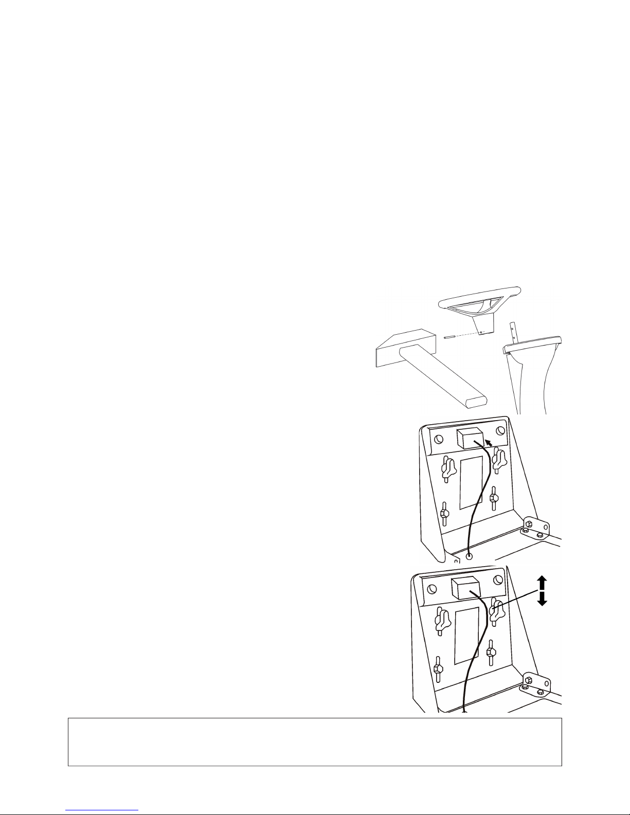
74
4. SBALLATURA
La falciatrice semovente č fornita in un imballo di trasporto. Alcune parti della macchina sono smontati nello stabilimento per
motivi di trasporto.ll loro montaggio va eseguito prima della messa in funzione.La sballatura della macchina a la sua preparazione
per il lavoro sono eseguite dal venditore nell'ambito dell'assistenza prevendita.
4.1 CONTROLLO DOPO LA SBALLATURA
Dopo aver eliminato l'imballo togliere con cautela la macchina dal bancale – utilizzare le rampe altrimenti c'č il rischio del
danneggiamento della macchina. Controllare se la macchina non č stata danneggiata durante il trasporto. Sballare anche tutte le
parti smontate e controllarle.
La confezione base contiene:
• falciatrice
• volante
• sedile
• documentazione ((Lista di imballaggio, Manuale di istruzioni della falciatrice, Manuale d'uso relativo al motore, Manuale
d'uso relativo all'accumulatore, Libretto di istruzioni)
4.1.1 LIQUIDAZIONE DELL'IMBALLO
Dopo aver sballato la macchina occorre liquidare l'imballo. La liquidazione va fatta rispettando la relativa legge vigente. La
separazione dell'imballo in base al materiale va eseguito secondo il relativo catalogo degli imballi.E' possibile affi dare questa
operazione ad un'azienda specializzata.
4.2 PREPARAZIONE ALLA MESSA IN FUNZIONE
Visto il carattere tecnico di questa attivitŕ, la preparazione della falciatrice per la messa in funzione verrŕ fatta dal venditore
(secondo le istruzioni della casa costruttrice).
4.2.1 MONTAGGIO DEL VOLANTE
Posizionare la falciatrice su una superfi cie piana ed allineare le ruote posteriori
in direzione diretta.
Inserire il volante e bloccarlo in posizione scelta tramite il perno 2 in dotazione
mettendolo nel rispettivo foro.
4.2.2 MONTAGGIO DEL SEDILE
Togliere l'imballo protettivo dal sedile. Installare il sedile al suo posto sulla macchina e
fi ssarlo inserendo le apposite viti nei relativi fori provvisti nel sedile.
4.2.3 REGOLAZIONE DELLA POSIZIONE DEL SEDILE
Eseguire la regolazione della posizione del sedile come segue:
Allentare le viti con le rosette plastiche. Spostare il sedile avanti o indietro nella
posizione richiesta. Fissare le viti con le rosette plastiche.
4.2.4 COLLEGAMENTO DELL'ACCUMULATORE
Durante l'avviamento dell'accumulatore procedere seguendo le istruzioni riportate nel
Manuale di istruzioni relativo all'accumulatore. L'accumulatore č montato sul lato
destro accanto alla colonna del sedile sotto il cofano del motore. Allentare le viti
sui morsetti d'uscita dell'accumulatore. Collegare il conduttore rosso all'uscita (+)
dell'accumulatore e bloccarlo con una vite. Collegare il conduttore marrone all'uscita
(-) dell'accumulatore e bloccarlo con una vite.
AVVERTENZA !!!
Il collegamento invertito dei conduttori puň risultare nel danneggiamento della macchina.
Nello staccare dell'accumulatore scollegare sempre l'uscita "–" dell'accumulatore come prima.
Osservare le istruzioni relative alla manutenzione riportate nel Manuale d'uso relativo all'accumulatore.
Page 77
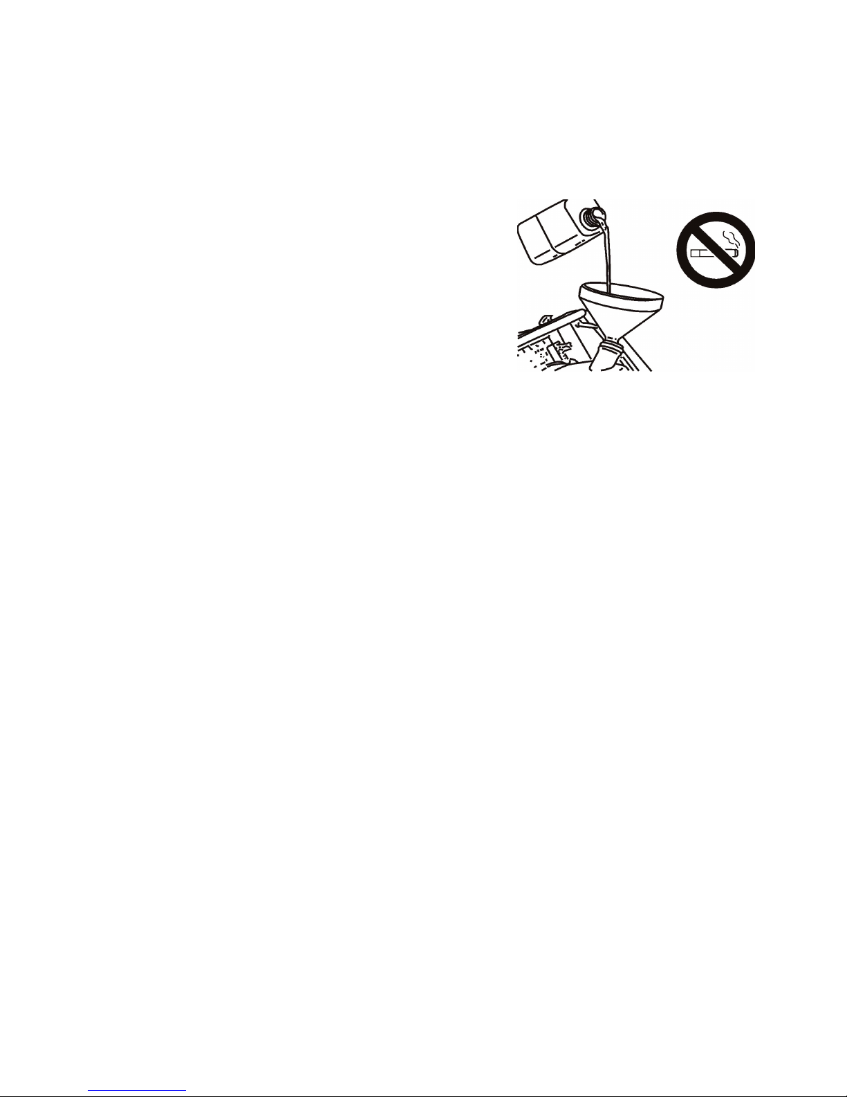
75
5. MESSA IN FUNZIONE
Visto il carattere tecnico di questa attivitŕ, la messa in funzione della falciatrice verrŕ fatta dal venditore (secondo le istruzioni
della casa costruttrice).
5.1 CONTROLLO DEL LIVELLO DELL'OLIO MOTORE
Procedere secondo il Manuale d'uso relativo al motore, osservare le istruzioni riportate nel capitolo 7.1 “Tabella riassuntiva dei
controlli e della manutenzione“.
5.2 CONTROLLO DELL'ACCUMULATORE
Procedere secondo il Manuale d'uso relativo all'accumulatore.
5.3 RIFORNIMENTO DI BENZINA
• Per motivi di sicurezza la macchina viene trasportata senza carburante.
• Riempire il serbatoio sempre solo al motore fermo e freddo.
• Utilizzare solo la benzina con numero di ottani 95 (Natural 95).
• Il serbatoio č ubicato nella colonna del sedile ed č di facile accesso dopo il
ribaltamento del sedile in avanti.
• Aprire lentamente il tappo del serbatoio. Nel serbatoio si puň creare la
sovrapressione dovuta ai vapori di benzina.
• Per il rifornimento di benzina usare il bidone con imbuto, non traboccare il
bidone.
• Il livello della benzina nel serbatoio si verifi ca tramite la fessura nella parte
sinistra della colonna del serbatoio.
• Sempre asciugare lo spazio attorno il tappo e il tappo stesso. Pulire
regolarmente il serbatoio interno perchč le eventuali impuritŕ nel carburante
possono causare un difetto.
• Durante il lavoro con il carburante non mangiare, non fumare e non usare le
fi amme.
Page 78
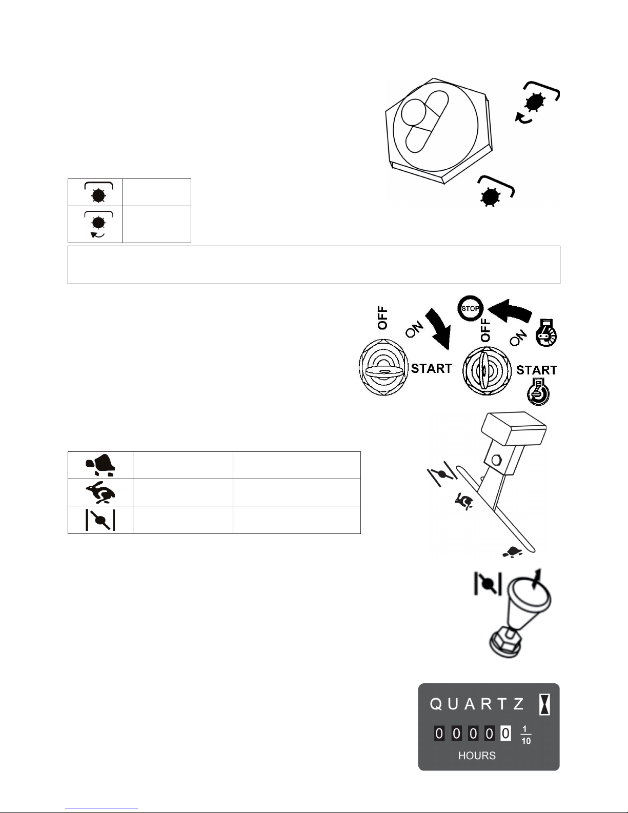
76
6. USO DELLA MACCHINA
6.1 DESCRIZIONE E FUNZIONAMENTO DEI
COMANDI
6.1.1 INTERRUTTORE DELL'APPARATO DI TAGLIO
L'interruttore dell'apparato di taglio inserisce la frizione elettromagnetica, di cui
la puleggia trasmette, attraverso una cinghia trapezoidale, la trazione dal motore
alla puleggia dell'apparato di taglio. L'interruttore č protetto nella posizione
„disinserito" contro l'eventuale inserimento indesiderabile. L'inserimento
si esegue tirando la levetta dell''interruttore e spostandola nella posizione
"inserito".
DISINSERITO
INSERITO
AVVERTENZA:
Se la leva č spostata nella posizione di trasporto (vedi cap.6.1.6), non č possibile attivare l'apparato di taglio.
. Un interruttore di sicurezza č integrato in questa posizione.
6.1.2 BLOCCHETTO DI ACCENSIONE
La chiave ha 3 posizioni:
OFF - l'accensione disattivata
ON - l'accensione attivata
START - l'avviamento motore
6.1.3 LEVA DELL'ACCELERATORE
Regola i giri del motore, puň assumere le seguenti posizioni:
(fi gura nel cap. 6.1.3)
MIN marcia in folle
MAX max. giri motore
DISPOSITIVO
D‘AVVIAMENTO *
avviamento motore a freddo
* Il dispositivo d'avviamento č montato sulla macchina in funzione al tipo del motore.
6.1.4 DISPOSITIVO D'AVVIAMENTO (PRIMER)
Tirando la levetta del dispositivo d'avviamento consente l'avviamento del motore a freddo.
E' montato sulla macchina in funzione al tipo del motore.
6.1.5 CONTATORE DI ORE DI FUNZIONAMENTO
Il contatore di ore di funzionamento č montato in funzione del tipo della macchina.
E' attivo solo se č inserita l'accensione e l'interruttore di sedile (si attiva automaticamente
con il peso dell'operatore).
Qualunque manomissione del contatore signifi ca la decadenza della garanzia. Nel caso di
qualsiasi anomalia del contatore, contattare subito il vostro centro di assistenza tecnica.
Page 79
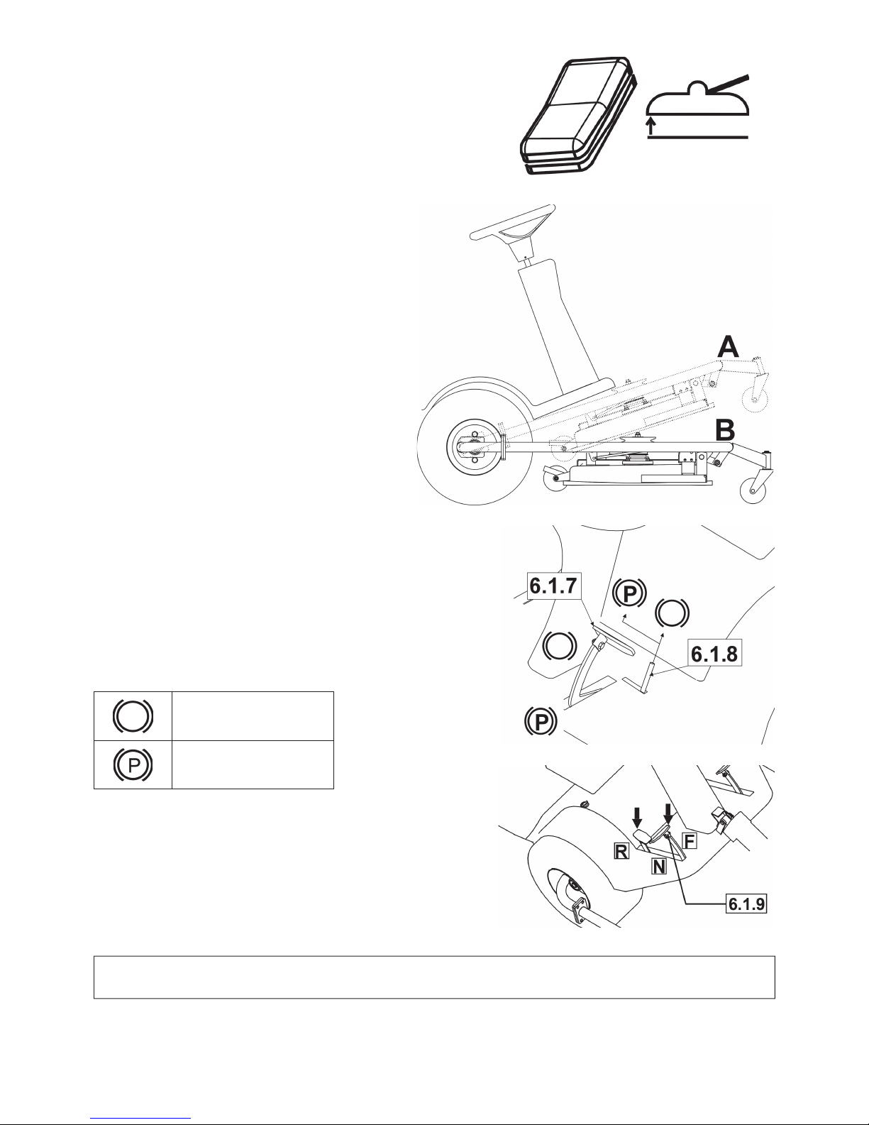
77
6.1.6 INTERRUTTORE DI SOLLEVAMENTO
DELL'APPARATO DI TAGLIO
Questo interruttore serve per sollevare l'apparato di taglio nella posizione di
trasporto a per abbassarlo nella posizione di lavoro regolata dalla leva 6.1.11.
Posizione dell'apparato di taglio sono come segue:
A - posizione di trasporto
B - posizione di lavoro
Per sollevare od abbassare premere l'interruttore e tenerlo
premuto.
Al raggiungimento della posizione estrema dell'apparato
di taglio, immediatamente lasciare l'interruttore.
Anche se le posizioni estreme sono dotate dalla
giunzione di sicurezza, se l'interruttore č premuto per
un tempo prolungato, puň verifi carsi il danneggiamento
dell'installazione elettrica.
6.1.7 FRENO
A pedale del freno premuto la falciatrice č frenata. Non usare mai
il freno contemporaneamente alla funzione di avanzamento
– c'č rischio del danneggiamento del cambio.
6.1.8 LEVA DEL FRENO DI STAZIONAMENTO
La leva del freno di stazionamento ha 2 posizioni. Prima di mettere la leva
nella posizione “P”, schiacciare il pedale del freno. Il disinnesto del freno
di stazionamento avviene schiacciando il pedale del freno, il bloccaggio
della leva viene automaticamente rilasciato.
SFRENATO
FRENATO
6.1.9 PEDALE DI AVANZAMENTO
Comanda la trazione delle ruote e regola la velocitŕ della macchina in
ambedue le direzioni.
avanzamento avanti: Premere lentamente il pedale con la punta di piede
in direzione „F“, piů si preme il pedale, piů la velocitŕ sale e vice versa.
avanzamento indietro:
Premere lentamente il pedale con il calcagno in direzione „R“, piů si
preme il pedale, piů la velocitŕ sale e vice versa.
Appena si rilascia il pedale, ritorna automaticamente nella posizione “N“
(folle) e la macchina si ferma.
AVVERTENZA !!!
La direzione della marcia si puň cambiare solo dopo l'arresto della macchina.
Page 80
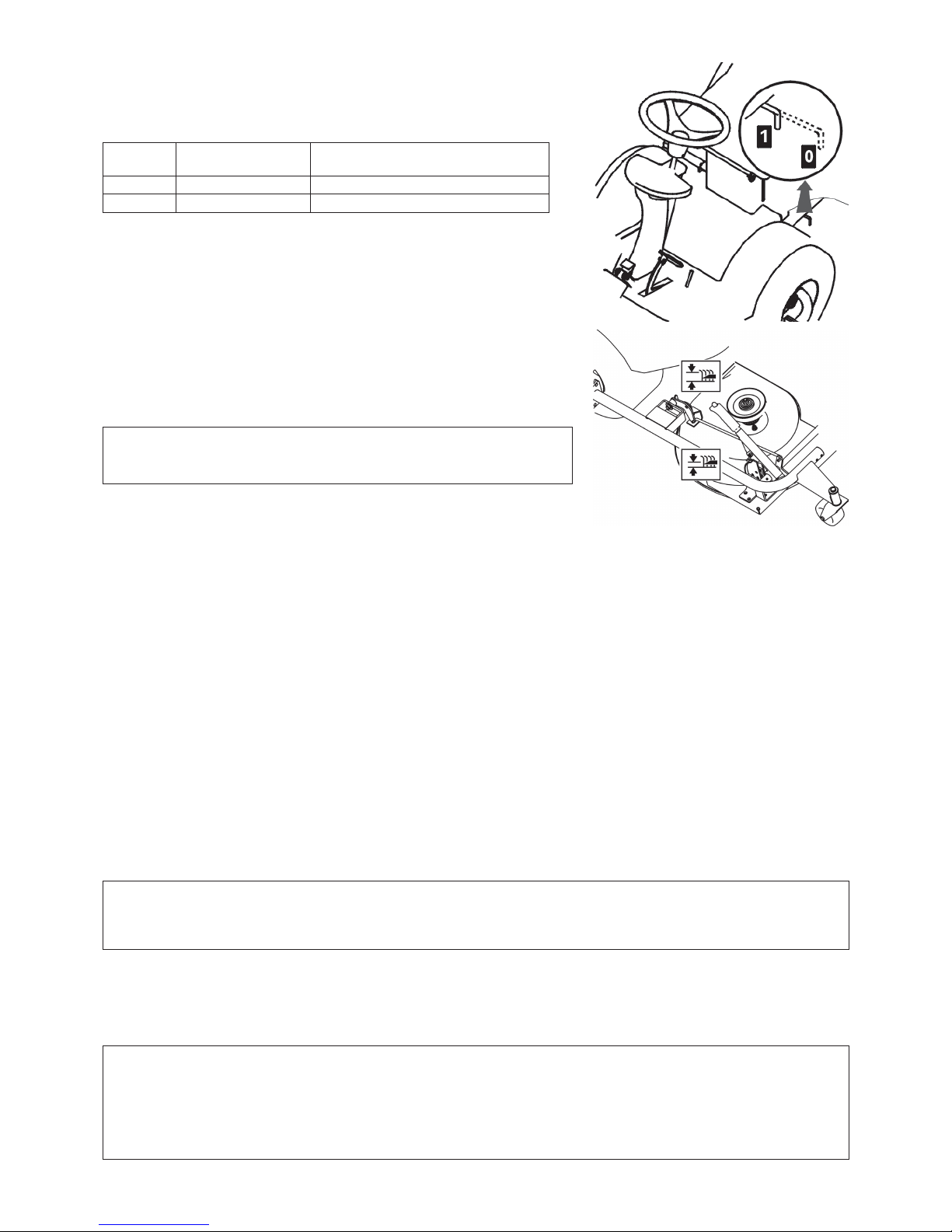
78
6.1.10 LEVA DEL BY-PASS
La leva del by-pass serve per disinserire la trasmissione della trazione alle ruote
anteriori.
Ha 2 posizioni:
Posizione Trazione delle ruote
anteriori
Uso
0
DISINSERITA Spinta della macchina, motore fermo
1
INSERITA Marcia, motore gira
6.1.11 LEVA DI REGOLAZIONE DELL’APPARATO DI TAGLIO IN
ALTEZZA
Serve per regolare l'apparato di taglio in altezza. Ha 8 posizioni di lavoro che
corrispondono all'altezza di taglio da 3 a 8 cm. Piů alto č il numero della posizione
della leva, piů alta č l'erba dopo la falciata.
AVVERTENZA:
Durante l'avanzamento senza il taglio, l'apparato di taglio deve essere
sollevato nella posizione di trasporto con l'interruttore 6.1.6.
6.2 FUNZIONAMENTO E COMANDO
La protezione antifortunistica della macchina
La falciatrice č dotata dei contatti di sicurezza che si chiudono tramite l'interruttore posizionato sotto il sedile. Il motore si
ferma automaticamente appena l'operatore abbandona il sedile. Il motore si avvia solo se l'interruttore dell'apparato di taglio č
nella posizione “disinserito” e l'apparato di taglio č sollevato nella posizione di trasporto e il pedale di avanzamento non č stato
schiacciato.
6.2.1 AVVIAMENTO MOTORE
• Controllare il livello della benzina nel serbatoio.
• Sedersi comodamente sul sedile della macchina, l'apparato di taglio sollevare con l'interruttore 6.1.6 nella posizione di
trasporto.
• Spostare l'interruttore dell'inserimento dell'apparato di taglio 6.1.1 nella posizione „DISINSERITO“.
• Attenzione, non schiacciare il pedale di avanzamento 6.1.9.
• Spostare la leva dell'acceleratore 6.1.3 nella posizione „MAX“.
• Tirate fuori il dispositivo d'avviamento 6.1.4.
• Non spostare la leva di sollevamento dell'apparato di taglio 6.1.11.
• Ruotare la chiave d'accensione 6.1.2 nella posizione "START“. La durata dell'avviamento non deve superare 10 secondi –
c'č rischio del danneggiamento dell'interruttore a batteria.
• Il motore "gira" - lasciare la chiave d'avviamento. La chiave ritorna automaticamente nella posizione "ON".
• Man mano spingere il dispositivo d'avviamento 6.1.4.
• Spostare lentamente la leva dell'acceleratore 6.1.3 nella posizione „MIN“ (abbassare i giri del motore).
• Lasciare il motore in marcia per alcuni minuti e dunque inserire l'apparato di taglio.
PERICOLO !
Mai lasciare il motore avviato nell'ambiente chiuso o mal ventilato.
I gas di scarico che contengono l'ossido di carbonio, sono molto pericolosi. Tenete le mani, piedi, i vestiti liberi lontano dalle
parti in movimento e dallo scarico.
6.2.2 ARRESTO DEL MOTORE
• Spostare la leva dell'acceleratore 6.1.3 nella posizione „MIN“.
• Disinserire l'apparato di taglio con l'interruttore 6.1.1 (vedi capitolo 6.2.4).
• Se il motore č surriscaldo, farlo girare per un po' al minimo.
• Spegnere il motore ruotando la chiave 6.1.2 nella posizione „STOP" e togliere la chiave dal blocchetto di accensione.
AVVERTENZA !!!
Mai fermare il motore lasciando semplicemente il sedile. La chiave d'accensione lasciata nella posizione "ON“ puň
danneggiare l'installazione elettrica. Ruotare sempre la chiave nella posizione "OFF" e toglierla dal blocchetto di accensione.
IMPORTANTE !!
Prima di spegnere il motore, abbassare i giri evitando il danneggiamento del motore e dello scarico nel caso
dell'autoaccensione.
Page 81

79
6.2.3 INSERIMENTO E DISINSERIMENTO DELL'APPARATO DI TAGLIO
a) Inserimento
• Spostare la leva dell'acceleratore 6.1.3 nella posizione „MAX“.
• Abbassare, con l'interruttore 6.1.6, l'apparato di taglio nella posizione di lavoro regolata dalla leva 6.1.11, nel caso contrario
c'č rischio di danneggiamento della cinghia trapezoidale.
• Spostare l'interruttore dell'apparato di taglio 6.1.1 nella posizione "INSERITO“.
L'apparato di taglio si inserisce solo se l'operatore sta seduto sul sedile della macchina
b) Disinserimento
• Spostare l'interruttore dell'apparato di taglio 6.1.1 nella posizione "INSERITO“.
• Se la guida abbandona il sedile, il motore si ferma automaticamente e si ferma anche l'apparato di taglio.
AVVERTENZA !!!
Mai fermare il motore lasciando semplicemente il sedile. La chiave d'accensione non ruotata dalla posizione “ON” nella
posizione “OFF” (STOP) signifi ca che l'installazione elettrica č sempre sotto tensione, puň verifi carsi il suo difetto.
6.2.4 REGOLAZIONE DELL'APPARATO DI TAGLIO IN ALTEZZA
L'apparato di taglio deve essere abbassato nella posizione di lavoro „B“ (vedi fi gura nel cap. 6.1.6) spostando l'interruttore 6.1.6
nella posizione „abbassamento“.
Spostare la leva di sollevamento dell'apparato di taglio 6.1.11 in direzione su, se si vuole impostare l'apparato di taglio piů alto
dalla terra, oppure giů, se si vuole impostare l'apparato di taglio piů vicino alla terra.
La posizione „1“ viene utilizzata per copiare la discontinuitŕ del terreno. Non usare tale altezza in modo permanente, in quanto
si potrebbe verifi care l'usura elevata delle parti dell'apparato di taglio.
L'apparato di taglio č dotato di 3 rotelle di spostamento che nel caso delle discontinuitŕ del terreno alzano il telaio con l'apparato
di taglio e servono come protezione dei coltelli taglienti contro il danneggiamento.
6.3 AVANZAMENTO
Prima di avanzare la macchina schiacciare il pedale del freno di servizio 6.1.7 per verifi care se il freno di stazionamento sia stato
disinserito. La leva del freno di stazionamento 6.1.8 non deve rimanere nella posizione „P“!
La leva del by-pass 6.1.10 deve essere spostata nella posizione “1”, il by-pass di avanzamento deve essere inserito.
Spostando la macchina sul posto da falciare, l'apparato di taglio deve essere disinserito (interruttore 6.1.1) e sollevato nella
posizione di trasporto spostando l'interruttore 6.1.6 nella posizione „sollevamento“.
Se si devono passare i dislivelli locali piů alti di 8 cm (bordi), usare sempre le rampe per non danneggiare l'apparato di taglio e
del cambio.
Eseguire l'avanzamento proprio come segue:
• Abbassare i giri motore spostando la leva dell'acceleratore 6.1.3 nella posizione „MIN“.
• Mettendosi in marcia spostare lentamente il pedale di avanzamento 6.1.9 n direzione richiesta: premendo velocemente il
pedale c'č rischio di un incidente.
• Se si vuole cambiare la direzione avanti-indietro, occorre fermare la macchina.Se la macchina non č ferma, si rischia
l'eventuale difetto della trasmissione.
• Non usare mai il pedale di avanzamento ed il freno contemporaneamente – c'č rischio del danneggiamento del cambio.
AVVERTENZA !!!
Per fermare la macchina lasciare gradualmente il pedale di avanzamento e poi schiacciare il pedale del freno.
Schiacciando la leva del freno il pedale di avanzamento si sposta automaticamente nella posizione folle. La traiettoria di
arresto č al di sotto di 2 m.
6.4 VELOCITA' DI AVANZAMENTO E IL TAGLIO DELL'ERBA
Spostare la leva dell'acceleratore 6.1.3 nella posizione „MAX. Regolare l'altezza dell'apparato di taglio con la leva 6.1.11 (vedi
il capitolo 6.2.4).
Generalmente vale che piů umida, alta e densa č l'erba, piů bassa dovrebbe essere la velocitŕ di avanzamento. Se la velocitŕ o il
carico sono troppo alti, i giri di rotazione dei taglianti si abbassano e di conseguenza si peggiora la qualitŕ di falciata.
Se l'erba č molto alta, occorre eseguire la falciata piů volte. Il primo taglio va fatto nell'altezza massima, eventualmente diminuendo
la larghezza di taglio, il taglio successivo va fatto giŕ nell'altezza richiesta.
Raccomandiamo di tagliare l'erba nella direzione longitudinale e incrociata. La sovraposizione del taglio precedente della
macchina consente aumentare l'effi cienza dei coltelli e nello stesso tempo migliora l'aspetto del terreno falciato.
Durante il movimento attraverso il terreno discontinuo la velocitŕ di avanzamento puň oscillare.
Raccomandiamo di usare, secondo le condizioni, le velocitŕ come segue:
Stato della superfi cie erbosa Velocitŕ raccomandata
alta, densa e umida 2 Km/ora
condizioni medie 3 - 5 Km/ora
erba bassa, secca 5 Km/ora
avanzamento senza l‘apparato di taglio inserito 7 Km/ora
6.5 MARCIA SUL PENDIO
Questa falciatrice č in grado di lavorare sui pendii fi no alla pendenza di 14 (25%). Durante il lavoro sul pendio applicare sempre
la velocitŕ di avanzamento piů bassa.
Camminare sempre nella direzione perpendicolare a linee di livello, su e giů. La marcia nella direzione delle linee di livello
č vietata. Scendendo i pendii e superando gli ostacoli andare ancora piů piano. Una precauzione particolare č richiesta quando
si vuole voltare o girare in pendenza. Se occorre arrestare in pendenza, usare sempre il freno di stazionamento. Se la macchina si
sovraccarica lavorando sui pendii oltre 14° (25°), puň verifi carsi un grave danneggiamento della scatola del cambio. Il costruttore
declina ogni responsabilitŕ dovuta a tali difetti.
Page 82

80
7. MANUTENZIONE DELLA MACCHINA
7.1 TABELLA RIASSUNTIVA DEI CONTROLLI E DELLA MANUTENZIONE
A stagione nita - prima di mettere la macchina fuori servizio
Prima della stagione
Ogni 100 ore
Ogni 50 ore
Ogni 25 ore
Un volta al mese
Regolarmente dopo ogni uso
Dopo le prime 5 ore
Dopo le prime 2 ore
Prima di ogni uso
Veri ca del livello dell‘olio (cambio, motore)
OO
Sostituzione dell‘olio motore O O 1,2 O
Sostituzione del ltro combustibile
O
Manutenzione dell‘accumulatore (controllo livello elettrolito, pulizia) O O
Aggiustaggio e controllo delle cinghie O O 4O O
Controllo del comando freno O O
Controllo della pressione nei pneumatici O O
Controllo del ssaggio dei cavi (innesti rapidi allentati) O O
Pulizia della falciatrice O O
Controllo delle giunzioni a vite O O O
Controllo della funzionalitŕ degli interruttori ed elementi di sicurezza O
Controllo ed aggiustamento del funzionamento del motore, cambio,
frizione elettromagnetica
O
Controllo e manutenzione del ltro aria, della candela d‘accensione,
l‘eventuale sostituzione
O 1,2
Controllo dello stato dell‘apparato di taglio (gioco, allineamento degli
alberi, controllo ed a latura dei coltelli taglienti)
O O 3
Legenda alla tabella:
1. Eseguire la sostituzione dell'olio piů frequentemente se la falciatrice viene piů caricata o se lavora nelle temperature esterne
attorno ai 35°C o superiori.
2. Nel caso in cui la macchina lavora in un ambiente polveroso, eseguire il controllo piů frequentemente.
3. Eseguire il controllo piů frequentemente se la macchina lavora in un ambiente sabbioso.
4. Eseguire il controllo piů frequentemente sempre se montata una nuova cinghia.
7.2 CONTROLLO DELLA PRESSIONE NEI PNEUMATICI
Mantenere sempre la pressione prescritta e verifi carla regolarmente. I valori diversi di quelli prescritti possono rendere piů
diffi cile la marcia ed eventualmente provocare la perdita del controllo della macchina. Il mantenimento della pressione prescritta
č importante anche per la falciata uniforme.
• Pressione nei pneumatici anteriori 80 - 140 kPa
• Pressione nei pneumatici posteriori 80 - 140 kPa
7.3 MANUTENZIONE A LAVORO FINITO
A falciata fi nita sollevare l'apparato di taglio nella posizione piů alta e spegnere il comando dei coltelli taglienti. Spegnere
l'accensione, premere il pedale del freno ed bloccare la macchina con il freno di stazionamento.
7.3.1 PULIZIA DELLA MACCHINA
Dopo ogni falciata rimuovere tutte le impuritŕ e residui erbosi dalla superfi cie della macchina e dal telaio dell'apparato di taglio.
AVVERTENZA !!!
Prima di iniziare la pulizia, lavaggio o riparazione della macchina togliere la chiave dal blocchetto d'accensione. Indossare
sempre le scarpe solide, guanti e vestiti destinati al lavoro. Evitare la dispersione del carburante, olio o altre sostanze nocive.
7.3.2 LAVAGGIO
Evitare il lavaggio con l'acqua negli appressi delle parti elettriche sul bordo strumenti, accumulatore, ecc. Si sconsiglia di lavare
la macchina per mezzo dell'acqua pressurizzata.
Lavare la macchina come riportato di seguito:
• Lavare la falciatrice su una superfi cie piana.
• Pulire, con una spugna e acqua con sapone, le parti in plastica.
• Smontare i perni 2 e il perno 3 (vedi fi g. nel cap. 7.13).
• Sollevare l'apparato di taglio dietro il telaio nella posizione verticale. Rimuovere con un raschietto e getto d'acqua i residui
erbosi dall'apparato di taglio.
Page 83
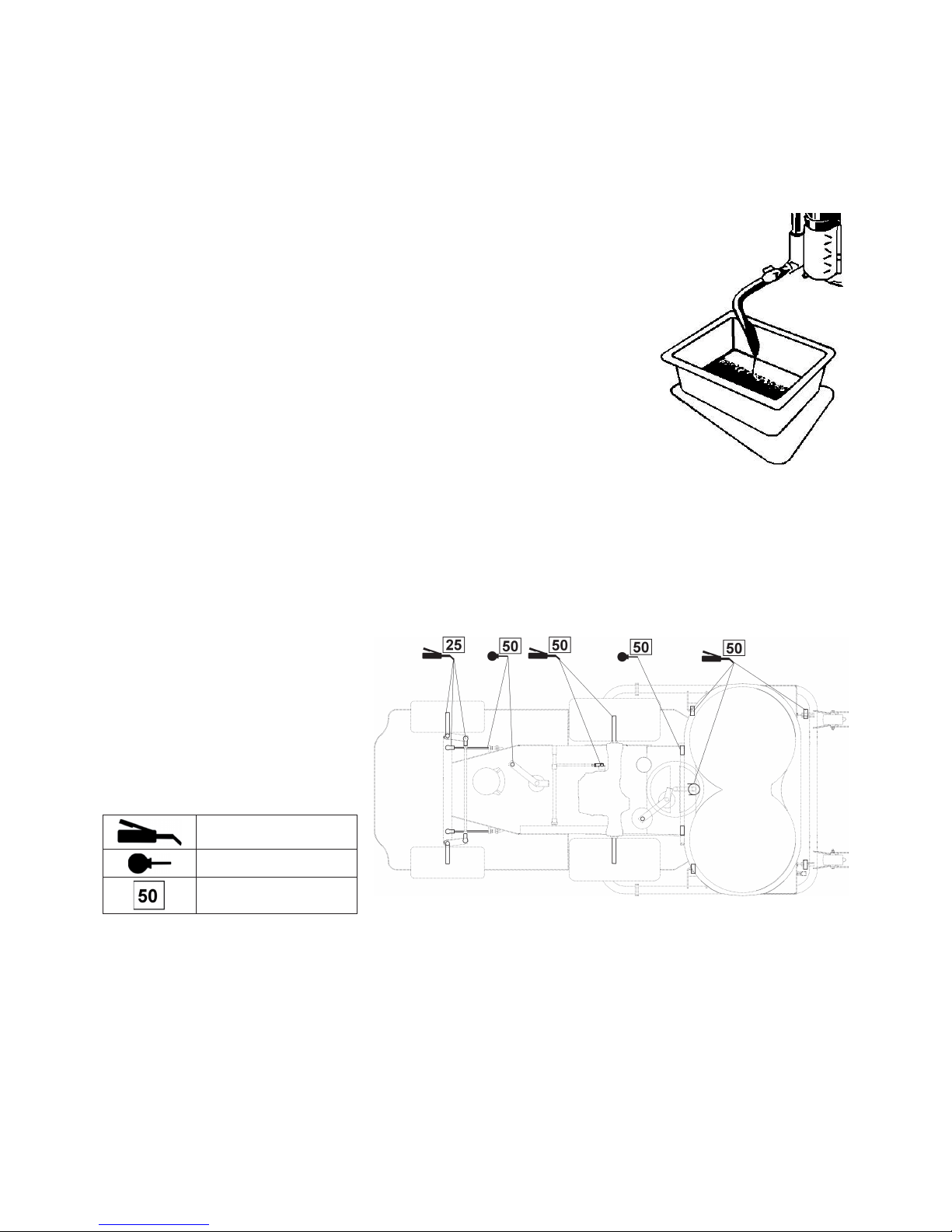
81
7.4 MANUTENZIONE DELL'ACCUMULATORE
Eseguire la manutenzione dell'accumulatore attenendosi alle istruzioni riportate nel Manuale d'uso relativo all'accumulatore.
7.5 MANUTENZIONE DEL MOTORE
Eseguire la manutenzione del motore attenendosi alle istruzioni riportate nel Manuale d'uso relativo al motore.
7.5.1 CONTROLLO DEL LIVELLO DELL'OLIO MOTORE
Eseguire il controllo dell'olio attenendosi alle istruzioni riportate nel Manuale d'uso relativo
al motore.
7.5.2 SOSTITUZIONE DELL'OLIO
Il motore č dotato di una vite di scarico dell'olio.
• Disporre sotto il motore un recipiente piatto di volume di almeno 2 litri. Rincalzare la
falciatrice sulla parte opposta alla vite di scarico per far fuoriuscire tutto l'olio.
• Svitare la vite di scarico e svitare il tappo di riempimento per rendere facile la fuoriuscita
dell'olio.
• Avvitare la vite di scarico, rabboccare il motore con la quantitŕ giusta dell'olio prescritto
(vedi il Manuale d'uso relativo al motore) e chiudere il tappo.
• Portare l'olio esaurito al luogo destinato allo smaltimento degli oli usati.
7.5.3 SOSTITUZIONE DEL FILTRO ARIA
Eseguire la sostituzione del fi ltro carburante attenendosi alle istruzioni riportate nel Manuale d'uso relativo al motore.
7.5.4 MANUTENZIONE DEL FILTRO ARIA
Eseguire la manutenzione attenendosi alle istruzioni riportate nel Manuale d'uso relativo al motore.
7.5.5 MANUTENZIONE DELLA CANDELA D'ACCENSIONE
Eseguire la manutenzione attenendosi alle istruzioni riportate nel Manuale d'uso relativo al motore.
7.6 LUBRIFICAZIONE
Lubrifi care tutti i punti di lubrifi cazione
secondo lo schema di lubrifi cazione e
controllare le singole funzioni a secondo il
riassunto riportato nel cap.7.1.
I cuscinetti delle pulegge tendicinghie,
pulegge conduttrice e cuscinetti dell'apparato
di taglio sono autolubrifi canti.
Prima di mettere la macchina fuori servizio
per un tempo prolungato lubrifi care
accuratamente tutti i punti che richiedono la
lubrifi cazione.
grasso
olio SAE 30
intervallo espresso in ore
Con il grasso plastico vanno lubrifi cate le seguenti parti:
• perni del movimento ruote
• snodi ad angolo dei tiranti di avanzamento - smontaggio, lubrifi cazione
• snodi ad angolo dei fusi a snodo - smontaggio, lubrifi cazione
• vite del tirante del freno - lubrifi care il tirante vicino al foro della vite
• vite del tirante del sollevamento dell'apparato di taglio - lubrifi care il tirante vicino al foro della vite
• snodi ad angolo dei tiranti dello sterzo - smontaggio, lubrifi cazione
• cuscinetti delle ruote posteriori
• perni delle ruote passanti nell'assale
• perno girevole centrale dell'assale posteriore - per mezzo di oliatore
• cuscinetto dell'albero volante - lubrifi care
• puleggia tendicinghia - smontare e lubrifi care i perni
Con l'olio vanno lubrifi cate le seguenti parti:
• tirante dello sterzo
• perni di bloccaggio dell'apparato di taglio
• punti girevoli del pedale di avanzamento
• punti girevoli del pedale del freno
Page 84
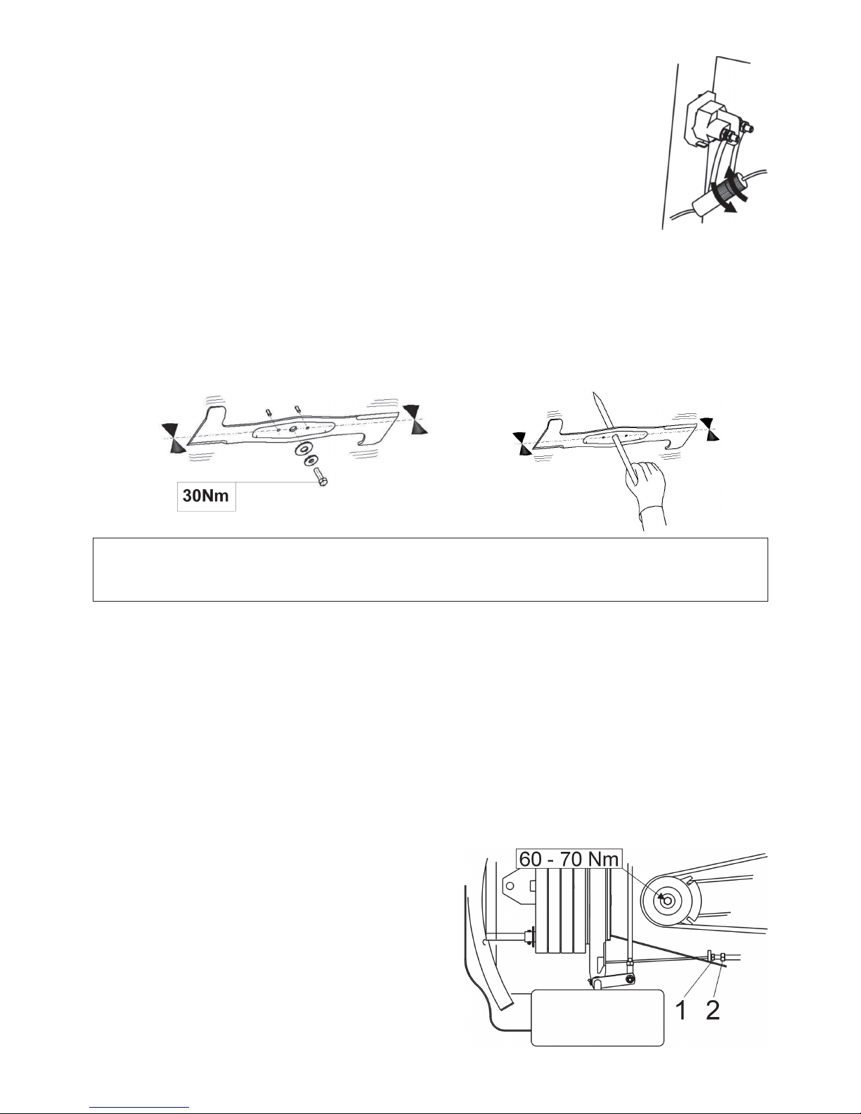
82
7.7 SOSTITUZIONE DEL FUSIBILE
Sollevare il cofano anteriore. Svitare il coperchio, estrarre il fusibile e inserire uno nuovo del valore
uguale a quello originale, 20 A.
Se neanche dopo la sostituzione del fusibile non č possibile avviare il motore, contattare il centro di
assistenza autorizzato.
7.8 SOLLEVAMENTO DELLA MACCHINA
Se si vuole sollevare a falciatrice, utilizzare il sollevatore e supporti.
Durante il sollevamento procedere come segue:
• Posizionare il sollevatore sotto il cambio e sollevare la parte anteriore della macchina.
• Inserire due supporti sotto le estremitŕ degli assali dentro la parte delle ruote posteriori.
• Sollevare la parte anteriore della macchina ed inserire due supporti sotto le estremitŕ di due perni delle ruote anteriori.
7.9 SOSTITUZIONE DEI COLTELLI DELL'APPARATO DI TAGLIO
I coltelli taglienti devono essere affi lati, staticamente bilanciati e dritti. Queste condizioni sono importanti per l'altezza uniforme
di falciata e qualitŕ di taglio. Lo spigolo non affi lato peggiora la qualitŕ del taglio e il risultato della raccolta dell'erba falciata.
AVVERTENZA !!!
Se si urta un oggetto solido, fermare e spegnere il motore e controllare i coltelli! Puň verifi carsi il danneggiamento o
taglio di spine tagliate. Sostituire le spine tagliate con quelle nuove in dotazione.
Controllare se le viti di fi ssaggio dei coltelli sono serrate a coppia prescritta.
Eseguire la sostituzione dei coltelli come segue:
• Sollevare l'apparato di taglio nella posizione di trasporto.
• Svitare i due coltelli, pulirli ed eseguire l'affi latura. Controllare il bilanciamento statico dei coltelli (vedi fi gura di sopra).
• Durante il montaggio fare attenzione che la scansa delle alette sia rivolta su, nell'interno del fulcro dell'apparato di taglio. Non
scambiare il coltello sinistro per quello destro.
Il coltello destro č dotato della vite sinistrorsa.
• Controllare lo stato delle spine di taglio che servono da protezione dell'apparato di taglio contro il danneggiamento. Se le
spine di taglio sono danneggiate, sostituirle subito.
• Serrare accuratamente le viti di fi ssaggio dei coltelli alla coppia prescritta di 30±3 Nm.
7.9.1 AFFILATURA DEI COLTELLI TAGLIENTI
Il coltello puň essere affi lato tramite lima o affi latrice. Non eseguire l'affi latura dei coltelli montati sull'apparato di taglio.
Dedicare un'attenzione elevata all'allineamento e bilanciamento dei coltelli. I coltelli non allineati o sbilanciati possono, con le
sue vibrazioni, causare un difetto del motore o dell'apparato di taglio.
Per il bilanciamento inserire la cacciavite nel foro di centraggio e regolare il coltello nella posizione orizzontale (vedi fi gura 7.9).
Appena il coltello rimane nella posizione descritta, č bilanciato. Se una delle estremitŕ prevale, eseguire l'affi latura di tale lato
solo dopo il bilanciamento del coltello.
Lo sbilanciamento statico ammissibile puň essere max. 2g.
7.10 MANUTENZIONE DELLO STERZO
Controllare regolarmente il gioco dello sterzo. Nel caso in cui si
riscontri il gioco maggiore, ripristinarlo. Per ripristinare il gioco
allineare per prima le ruote in direzione diritta. Allentare il dado 1 e
ruotando la vite di registrazione 2 sull'estremitŕ del tirante ripristinare
il gioco della catena al minimo. Dunque serrare il dado 1. Eseguire
la stessa registrazione anche sull'altra estremitŕ della catena. Fare
attenzione che i tiranti sulle due estremitŕ della catena abbiano la
stessa tensione.
Page 85
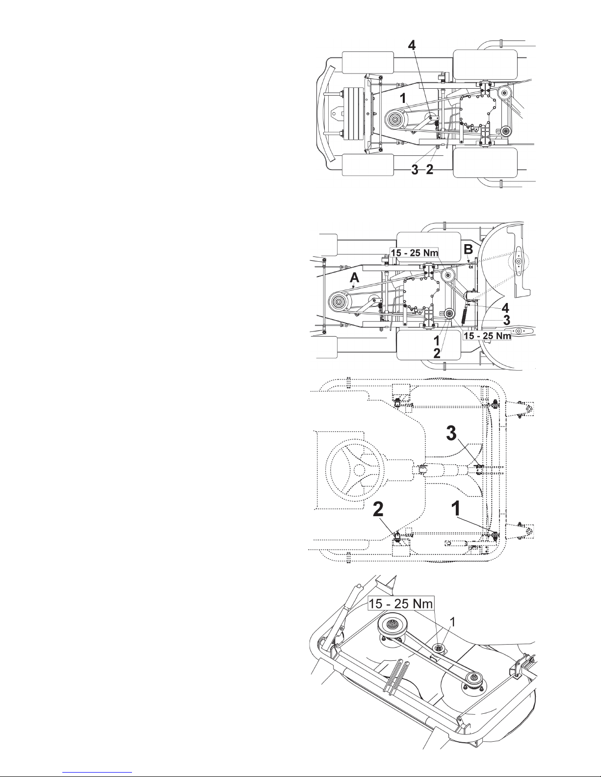
83
7.11 CONTROLLO ED AGGIUSTAMENTO
DELLA CINGHIA COMANDO
AVANZAMENTO
La cinghia 1 ha una tensione corretta se, applicando la forza di
4kp sulla cinghia nella metŕ di distanza tra le pulegge, si verifi ca la
defl essione della cinghia di circa 1,5 cm. Eseguire la registrazione
della tensione della cinghia ruotando il dado 3 sulla vite 2 che
tende la molla a tensione.
7.12 CONTROLLO ED
AGGIUSTAMENTO DELLE
CINGHIE TRAPEZOIDALI DEL
COMANDO DELL'APPARATO DI
TAGLIO
Cinghia trapezoidale A:
La cinghia 1 ha una tensione corretta se, applicando la forza
di 4kp sulla cinghia nella metŕ di distanza tra le pulegge, si
verifi ca la defl essione della cinghia di circa 1,5 cm. Eseguire
la registrazione della cinghia spostando la puleggia 2 a dado 1
allentato. A registrazione eseguita serrare il dado 1.
Cinghia trapezoidale B:
La cinghia comando dell'apparato di taglio viene tesa tramite
una puleggia con una molla. Se si perde la tensione visto il carico
della cinghia, aumentare la tensione spostando l'anello della molla
3 nell'altro foro del braccio 4 della puleggia di tensionamento.
7.13 ESTRAZIONE DELL'APPARATO
DI TAGLIO DALLA MACCHINA
• Abbassare l'apparato di taglio nella posizione di lavoro
spostando l'interruttore 6.1.6. Al raggiungimento della
posizione lasciare subito l'interruttore.
• Tirando la leva della puleggia di tensionamento 4 (fi g. 7.12)
liberare la cinghia trapezoidale ed estrarla.
• Sfi lare la molla 3 (fi g. 7.12) dal braccio della puleggia di
tensionamento.
• Sfi lare i copigli fl essibili dai perni anteriori 2 e da due perni
posteriori 1 della sospensione dell'apparato di taglio.
• Smontare il perno 3 e la vite di sollevamento dell'apparato di
taglio.
• Con le tenaglie sfi lare i due perni posteriori 1 della sospensione
dell'apparato di taglio.
Nello sfi lare fare attenzione alle dita e alle mani, per
evitare l'infortunio.
• Sfi lare i perni anteriori della sospensione 2.
• Sfi lare lentamente l'apparato di taglio dalla macchina.
7.14 AGGIUSTAMENTO DELLA
CINGHIA DENTATA COMANDO
DEI COLTELLI
• Abbassare l'apparato di taglio nella posizione di lavoro
spostando l'interruttore 6.1.6.
Al raggiungimento della posizione lasciare subito
l'interruttore.
• Smontare il coperchio di protezione della cinghia dentata.
• Allentare il dado 1 e tendere la cinghia spostando la puleggia
di tensionamento.
• Controllare la tensione. La cinghia ha una tensione corretta
se, applicando la forza di 4kp sulla cinghia nella metŕ di
distanza tra le pulegge, si verifi ca la defl essione della cinghia
di circa 0,5 cm.
• Serrare il dado 1 e rimontare il coperchio di protezione.
Page 86
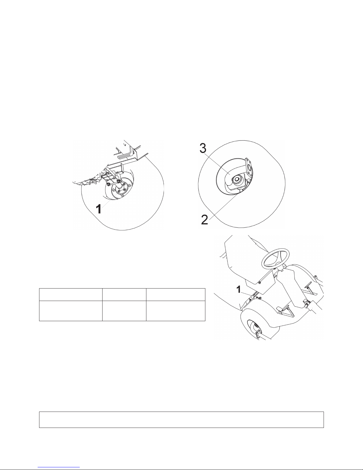
84
7.15 SOSTITUZIONE DELLE CINGHIE
Si tratta di una operazione impegnativa, affi darla al centro di assistenza autorizzato.
7.16 SOSTITUZIONE DELLA RUOTA
• Prima di sostituire una ruota fermare il motore e togliere la chiave del blocchetto di accensione.
• Bloccare la macchina sui supporti proseguendo come descritto nel cap. 7.8.
• Abbassare l'apparato di taglio nella posizione di lavoro spostando l'interruttore 6.1.6. Al raggiungimento della posizione
lasciare subito l'interruttore.
• Per sostituire la ruota anteriore estrarre l'apparato di taglio dalla macchina (vedi cap. 7.13) e scollegare il telaio anteriore
dell'apparato di taglio.
• Tirando la leva della puleggia di tensionamento 4 liberare la cinghia trapezoidale B (fi g. 7.12) e sostituirla.
• Sul lato interno della ruota svitare 4 viti 1, smontare l'anello di sicurezza e sfi lare il supporto del telaio anteriore 3.
• Svitare 4 viti 2 e rimuovere la ruota.
• Per sostituire la ruota posteriore rimuovere il suo coperchio di protezione, smontare l'anello di sicurezza, il supporto e sfi lare
la ruota dall'albero.
Al rimontaggio della ruota anteriore o quella posteriore procedere nella sequenza inversa delle operazioni.
Prima di montare la ruota pulire tutte le parti e lubrifi care le parti di contatto leggermente con il grasso plastico.
7.17 MANUTENZIONE DELLA
TRASMISSIONE IDROSTATICA
Per il funzionamento affi dabile delle trasmissioni occorre mantenere il
corretto livello dell'olio. I valori prescritti sono riportati nella tabella seguente.
Il foro di riempimento 1 si trova giů vicino al sedile (vedi fi gura). In caso dei
problemi con la trasmissione contattare immediatamente il centro d'assistenza
autorizzato, c'č rischio del danneggiamento grave della trasmissione.
Tipo frizione
Specifi ca
dell‘olio
Livello dell‘olio
Tuff-Torq K46, idrostatico
SAE 10W-30,
API CD
min. nella metŕ
dell‘altezza del serbatoio
di compensa
7.18 REGISTRAZIONE DEL FRENO
Se i freni iniziano a perdere l'effi cienza, fare eseguire la loro regolazione in
offi cina autorizzata.
7.19 RIASSUNTO DELLE COPPIE DI SERRAGGIO DELLE GIUNZIONI A VITE
Apparato di taglio: Capitolo:
Vite centrale del coltello 30 ± 3 Nm 7.9
Dado M12 della puleggia del comando del taglio 45 - 55 Nm 7.14
Vite M8x20 del braccio della puleggia tenditore comando dell'apparato di taglio 25 - 35 Nm 14
Motore:
Vite della frizione elettromagnetica 60 - 70 Nm 7.10
Vite del supporto della puleggia tenditore di avanzamento … 25 – 35 Nm 7.10 (pos. 4)
AVVERTENZA !!!
Allo smontaggio e rimontaggio i dadi autobloccanti devono essere sostituiti da quelli nuovi.
Page 87

85
8. RICERCA QUASTI
Non eseguire le operazioni di assistenza senza il relativo equipaggiamento tecnico e la qualifi ca professionale. Le
operazioni riportate di seguito possono essere effettuate dall'utente della macchina. Le operazioni ivi non riportate,
eseguite dall'utente, risultano nella decadenza della garanzia.
Il costruttore non risponde per i danni dovuti all'esecuzione non a regola d'arte delle operazioni di assistenza non
autorizzate da parte dell'utente.
Anomalia, difetto Rimozione
L‘apparato di
taglio non taglia
in modo uniforme
Rimuovere l‘erba accumulata
dal lato inferiore dell‘apparato di taglio.
Ve r ifi care se i coltelli sono affi lati e se non sono deformati.
Controllare il serraggio dei coltelli.
Controllare se la regolazione dell‘apparato di taglio in altezza corrisponde ai valori riportati nei cap.
6.1.11 e 6.2.4. Nel caso contrario eseguire una nuova regolazione.
Controllare la tensione delle cinghie comando secondo i cap. 7.12 e 7.14. Se necessario, eseguire la
regolazione della tensione.
Controllare le lame dei coltelli. Se danneggiate o eccessivamente usurate, sostituirle.
Controllare i corpi dei cuscinetti per l‘eventuale danneggiamento. Se necessario eseguire la riparazione o sostituirli.
Tra i rotori dei
coltelli rimane
una striscia non
falciata
Se viene tagliata l‘erba densa o eccessivamente bagnata, una striscia puň rimanere non falciata.
La velocitŕ di avanzamento va adattata alle condizioni di taglio inserendo la marcia corrispondente.
Il motore dovrebbe girare alla farfalla dell‘acceleratore interamente aperta.
Controllare se i coltelli sono affi lati e se non sono danneggiati. Se necessario, sostituire i coltelli.
Controllare la tensione delle cinghie di comando secondo i cap. 7.12 e 7.14. Se necessario, eseguire la
regolazione della tensione.
Controllare i corpi dei cuscinetti per l‘eventuale danneggiamento. Se necessario eseguire la riparazione o
sostituirli.
L‘apparato di
taglio strappa le
piote
Controllare l‘altezza di taglio e se necessario, regolarla. Lo strappo delle piote si verifi ca piů
frequentemente sulle superfi ci discontinue.
Controllare i corpi dei cuscinetti per l‘eventuale danneggiamento. Se necessario eseguire la riparazione o
sostituirli.
Controllare se i coltelli non sono storti. Se necessario, sostituire i coltelli.
La cinghia
comando apparato
di taglio si
ferma durante il
funzionamento
La cinghia di comando dell‘apparato di taglio puň essere danneggiata se durante il funzionamento della
macchina salta dalla puleggia.
Se salta anche dopo la prova eseguita secondo i passi seguenti, la cinghia va sostituita.
Controllare la tensione della cinghia secondo il cap. 7.12 Se necessario eseguire la regolazione.
Controllare la guida della cinghia.
Controllare la regolazione dell‘altezza di taglio, se necessario, regolarla.
Ve r ifi care se un corpo estraneo non impedisca il movimento della cinghia. Rimuovere eventualmente il
corpo estraneo.
- Controllare tutte le pulegge. Le pulegge rotte o storte possono causare i problemi.
Se necessario, sostituirle.
Controllare la superfi cie interna della puleggia sul motore. Se č ruvida o se presenta rotture, la pulleggia
va sostituita.
- Controllare l‘usura delle parti del meccanismo di tensionamento, se necessario, sostituire le parti usurate.
La cinghia
comando taglio
slitta
Se l‘erba č troppo alta o bagnata, la cinghia puň slittare durante la falciata.
Controllare se la cinghia non č usurata. Nel caso positivo, sostituirla.
Controllare la tensione della cinghia secondo il cap. 7.12 del Manuale. . Se necessario, eseguire la
regolazione della tensione.
Controllare la molla di tensionamento del meccanismo di tensionamento della cinghia della falciata.
Sostituire la molla danneggiata o allargata.
La cinghia
comando
taglio si usura
eccessivamente
Controllare tutti i punti della guida della cinghia.
Ve r ifi care se un corpo estraneo non impedisca il movimento della cinghia. Rimuovere eventualmente il
corpo estraneo.
Controllare le pulegge, se sono danneggiate, sostituirle.
Controllare la regolazione dell‘altezza di taglio, se necessario, regolarla.
Controllare la tensione della cinghia di avanzamento secondo il cap. 7.12 . Se necessario, eseguire la
regolazione della tensione.
Non si riesce a
mettere in moto i
coltelli
Controllare se la cinghia non č danneggiata o usurata. Nel caso positivo, sostituirla. Se č libera, sostituirla.
Controllare la molla del meccanismo di tensionamento. Sostituire la molla danneggiata o rotta.
Ve r ifi care se un corpo estraneo non impedisca il movimento della cinghia. Rimuovere eventualmente il
corpo estraneo.
I coltelli si
fermano con
ritardo
Controllare la tensione della cinghia di avanzamento secondo il cap. 7.12. Se necessario, eseguire la
regolazione della tensione. Se non č possibile effettuare l‘ulteriore tensionamento della cinghia per
l‘usura notevole, montare una cinghia nuova.
Ve r ifi care se un corpo estraneo non impedisca il movimento della cinghia. Rimuovere eventualmente il
corpo estraneo.
Controllare il funzionamento della frizione elettromagnetica, se si disinserisce correttamente. Se non
funziona correttamente, fate sostituire o riparare la frizione in offi cina autorizzata.
Page 88

86
Durante
l‘attivazione
dell‘apparato di
taglio si veri cano
delle vibrazioni
eccessive della
cinghia
Controllare se i coltelli non sono storte, controllare anche il loro bilanciamento.
Se deformati, sostituirli.
Controllare se la cinghia non dimostra gli spazi bruciati o irregolaritŕ che potrebbero causare le vibrazioni.
Sostituire la cinghia danneggiata.
Controllare se i coltelli non sono usurati o danneggiati. Se necessario, sostituirle.
Controllare il funzionamento della frizione elettromagnetica, se si inserisce correttamente. Se non
funziona correttamente, fate
sostituire o riparare la frizione in o cina autorizzata.
Controllare la super cie interna della puleggia sul motore. Se ruvida o se presenta rotture, la puleggia va
sostituita.
Controllare se sul lato inferiore dell‘apparato di taglio non si trova l‘erba accumulata. L‘accumulo
dell‘erba va rimosso.
Controllare se il difetto non sta nel ssaggio motore. Se necessario serrare le viti o sostituirle.
Controllare la tensione della cinghia di avanzamento secondo il cap. 7.12 . Se necessario, eseguire la
regolazione della tensione.
La cinghia di
avanzamento
slitta
Controllare la tensione della cinghia di avanzamento secondo il cap. 7.11. Se necessario eseguire la
regolazione della sua tensione.
Controllare se la cinghia non č danneggiata o usurata.
Controllare se il meccanismo della frizione di avanzamento non č bloccato da un corpo estraneo.
Rimuovere eventualmente il corpo estraneo.
Controllare, se la puleggia motore o cambio non č danneggiato. Se necessario, sostituirla.
La cinghia di
avanzamento
scricchiola
Controllare la tensione della cinghia di avanzamento secondo il cap. 7.11 e il funzionamento del freno. .
Se necessario eseguire la regolazione della tensione della cinghia. Se il freno non funziona correttamente,
fare eseguire la sua regolazione in o cina autorizzata.
La cinghia di
avanzamento
della macchina
salta durante il
funzionamento
Controllare la tensione della cinghia di avanzamento secondo il cap. 7.11. Se necessario eseguire la
regolazione della sua tensione.
Controllare la guida della cinghia.Se necessario eseguire la regolazione.
Controllare se le puleggie non sono danneggiate. Se necessario, sostituirle.
Controllare il tra erro del meccanismo della frizione di avanzamento. Se ci sono deviazioni, il supporto
delle pulegge della frizione puň risultare deformato. Se necessario, sostituirla.
La macchina
non si muove
al premere
del pedale di
avanzamento
Controllare la tensione della cinghia di avanzamento secondo il cap. 7.11. Se necessario eseguire la
regolazione della sua tensione.
Controllare la puleggia del motore e del cambio per le fessure danneggiate o tagliate. Se necessario, sostituirla.
Durante
l‘avanzamento
si veri cano le
vibrazioni estreme
Controllare se le pulegge non sono danneggiate o deformate. Se necessario, sostituirle.
Controllare se la cinghia di avanzamento non dimostra i punti bruciati o altre irregolaritŕ.
Se necessario, sostituirle.
Controllare la tensione della cinghia di avanzamento secondo il cap. 7.11. Se necessario eseguire la
regolazione della sua tensione.
Controllare il bilanciamento dei coltelli taglienti. Se necessario, bilanciarli o sostituirli.
Il motore non gira Controllare se la benzina č nel serbatoio.
Controllare se č stata osservata la procedura dell‘avviamento del motore (vedi il capitolo 6.2.1).
Controllare il fusibile.
Controllare se la tensione su due morsetti dell‘accumulatore arriva a 12 V. Nella macchina nuova
controllare se l‘accumulatore č stato attivato e carico.
Rimuovere la candela d‘accensione nelle macchine nuove e veri care, se nel cilindro non si č accumulato
olio dovuto alla manomissione.
Controllare se tutti i collegamenti dei conduttori sono corretti e se gli interruttori dell‘installazione
elettrica sono funzionanti.
Riprovare il motore secondo le istruzioni riportate nel Manuale di istruzioni relativo al motore fornito dal
costruttore.
Fate provare l‘installazione elettrica della macchina in o cina autorizzata.
Il motore gira ma
non si avvia
Controllare se č stata osservata la procedura dell‘avviamento del motore (vedi il capitolo 6.2.1).
Controllare se la benzina nel serbatoi č pulita.
Controllare se il ltro di benzina non č intasato.
Veri care se la leva dell‘acceleratore si trova nella posizione „PRIMER“
Riprovare il motore secondo le istruzioni riportate nel Manuale di istruzioni relativo al motore fornito dal
costruttore.
Fate provare il cablaggio e gli interruttore in o cina autorizzata.
La macchina non
puň essere spinta
o si spinge con
di coltŕ
Controllare se la leva del by-pass si trova nella posizione “0“.
Durante
l‘avanzamento si
sente „ schio“
Controllare lo stato delle cinghie, delle pulegge di tensionamento e di guida.
Se i problemi perdurano, contattare immediatamente l‘o cina autorizzata.
Page 89

87
8.1 COME ORDINARE I PEZZI DI RICAMBIO
Si consiglia di utilizzare solo i pezzi di ricambio originali che garantiscono la sicurezza e l'intercambiabilitŕ. Ordinare i pezzi di
ricambio solo presso un venditore autorizzato o nella rete assistenziale che č informata sulle modifi che tecniche attuali eseguite
sui prodotti nel corso della produzione. Per l'identifi cazione veloce, facile e precisa di un pezzo di ricambio richiesto riportare
sull'ordine sempre il numero di fabbricazione che si trova sul l'altro lato dell'imballo del presente pubblicazione. Riportare,
altresě, l'anno di produzione della macchina che si trova sulla targhetta di fabbricazione sotto il sedile.
8.2 GARANZIA
Le condizioni di garanzia sono riportati nel certifi cato di garanzia consegnato sempre assieme al prodotto da parte del
venditore.
9. MANUTENZIONE A STAGIONE FINITA, MESSA DELLA
MACCHINA FUORI SERVIZIO
A stagione fi nita o se non usata per piů di 30 giorni č idoneo di preparare immediatamente la falciatrice alla messa fuori
servizio.
Se il carburante rimane nel serbatoio, senza muoversi piů di 30 giorni, puň diventarne il sedimento che puň compromettere il
carburatore e il funzionamento del motore. Svuotare il serbatoio.
PERICOLO !
Mai mettere la falciatrice fuori servizio con carburante nel serbatoio in luoghi poco ventilati dove sono i vapori di
carburante, fuochi aperti, scintille o fi amme d'accensione, riscaldamento centrale, focolaio, stracci asciutti, ecc.
Manovrare con cautela i combustibili e lubrifi canti, sono altamente infi ammabili e il trattamento inattento puň causare
gravi scottature o infortuni o danneggiare i beni.
Svuotare il serbatoio solo in un recipiente prescritto a tale scopo, all'esterno, in assenza di fi amme aperte.
La procedura raccomandata per la messa fuori servizio della falciatrice:
• Pulire accuratamente tutta la falciatrice
• Sostituire i pezzi difettosi o usurati e serrare tutte le viti allentate e tutti i dadi allentati.
• Preparare il motore per la sua messa fuori servizio secondo il manuale d'uso e di manutenzione relativo al motore.
• Lubrifi care tutti i punti di lubrifi cazione secondo lo schema di lubrifi cazione (vedi cap. 7.6).
• Allentare la cinghia trapezoidale del comando dell'apparato di taglio (capitolo 7.12)
• Rimuovere l'accumulatore, pulirlo, rabboccarlo con l'acqua distillata fi no alle parti posteriori degli anelli dei fori di riempimento
e ricaricarlo.
L'accumulatore non ricaricato puň congelare e rompersi. Depositare l'accumulatore in un ambiente asciutto e freddo. Ricaricare
l'accumulatore ogni 30 giorni e controllare regolarmente la sua ricarica.
• La falciatrice va depositata coperta in un ambiente pulito e secco.
Il modo migliore per assicurare il funzionamento della falciatrice per la stagione successiva consiste in una revisione annuale e
aggiustamento presso il centro d'assistenza autorizzato.
10. SMALTIMENTO DELLA MACCHINA
Alla fi ne della durata della vita della macchina č l'utente obbligato eseguire il suo smaltimento. La liquidazione puň essere fatta
usando due procedimenti seguenti:
a) Consegnare la macchina ad una ditta specializzata in tale attivitŕ (parco del rottame, parco del rottame di automobili, depositi
di scarichi secondari,... ecc ). Dalla consegna della macchina per la liquidazione si avrŕ il relativo certifi cato.
b) Liquidare la macchina con le proprie forze. In tal caso si consiglia di procede come segue:
• seguire la liquidazione con l'utilizzo di materie prime secondarie ai sensi della legge sui rifi uti.
• Smontare tutta la macchina.
• Pulire, conservare e depositare in magazzino tutti i pezzi che possono essere ancora utilizzati in futuro.
• Classifi care le parti rimanenti dividendoli in componenti non nocivi all'ambiente e in componenti pericolosi per l'ambiente,
p.es. pezzi in gomma (anelli di tenuta), residui dei lubrifi canti nei cuscinetti o trasmissioni. I componenti nocivi all'ambiente
vanno trattati conformemente alle legge sui rifi uti in vigore nel paese di chi usa la macchina, nella Repubblica ceca, p.es., si
tratta della legge sui rifi uti n . 185 del 2001.
• La classifi cazione dei rifi uti si esegue secondo il Catalogo di scarichi e rottami conformemente al rispettivo decreto. I
componenti innocui dal punto di vista ecologico si trattano nello stesso modo come gli scarichi riutilizzabili.
Page 90

88
La societŕ Seco GROUP a.s. continua a sviluppare e perfezionare tutte le macchine fabbricate e per questo motivo possono
verifi carsi alcune deviazioni, rispetto alla realtŕ, nel testo e nelle illustrazioni riportate nel presente manuale. . Di tale fatto non
puň risultare nessun diritto. Stampare, copiare, pubblicazione e traduzione (pure delle parti del testo) non č ammesso senza il
previo consenso scritto da parte della Seco GROUP a.s..Il costruttore si riserva il diritto di apportare le modifi che.
Page 91

89
SOMMAIRE
CE Déclaration de conformité ..........................................90
Avant-propos ..................................................................... 91
1. Protection de la santé et sécurité de travail ....... 92
1.1 Consignes de sécurité ......................................... 92
Représentation graphique des mises
en garde et des avertissements ........................... 93
1.1.1 Travail sur la pente ............................................. 93
1.1.2 A ne pas faire ...................................................... 93
1.1.3 Sécurité des enfants ............................................93
1.1.4 Sécurité d’incendie ............................................. 93
2. Utilisation et notice technique ..........................94
2.1 Utilisation de la machine ...................................94
2.2 Notice technique ................................................ 94
2.2.1 Châssis de la machine ........................................94
2.2.2 Moteur y compris l’installation électrique ........94
2.2.3 La boîte d’engrenages y compris
la traction des roues avant .................................94
2.2.4 Essieu arrière avec
roues y compris la direction...............................94
2.2.5 By-pass................................................................94
2.2.6 Capotage et poste de l’opérateur ........................94
2.2.7 Dispositif de coupe ............................................ 94
2.3 Marquage ............................................................94
3. Paramètres techniques ....................................... 95
4. Déballage ............................................................ 96
4.1 Contrôle après le déballage ................................ 96
4.1.1 Liquidation de l’emballage .................................96
4.2 Préparation pour la mise en service ..................96
4.2.1 Montage du volant .............................................96
4.2.2 Montage du siège ................................................ 96
4.2.3 Ajustage de la position du siège ......................... 96
4.2.4 Raccordement de l’accumulateur ......................96
5. Mise en service ................................................... 97
5.1 Contrôle du niveau d’huile dans le moteur .......97
5.2 Contrôle de l’accumulateur................................ 97
5.3 Remplissage du réservoir par de l’essence .........97
6. Manoeuvre de la machine ..................................98
6.1 Description et fonction des manipulateurs ....... 98
6.1.1 Interrupteur du dispositif de coupe ..................98
6.1.2 Boîte de connexion ............................................. 98
6.1.3 Manette de gaz ................................................... 98
6.1.4 Saturateur ........................................................... 98
6.1.5 Compteur horaire ..............................................98
6.1.6 Interrupteur de levage du dispositif de coupe ....99
6.1.7 Frein ................................................................... 99
6.1.8 Levier du frein de parcage ................................. 99
6.1.9 Pédal de course ...................................................99
6.1.10 Levier du by-passu .............................................99
6.1.11 Levier d’ajustement de la hauteur
du dispositif de coupe ......................................100
6.2 Service et manipulation .................................. 100
6.2.1 Démarrage du moteur ..................................... 100
6.2.2 Arrêt du moteur ............................................... 100
6.2.3 Enclenchement et mise hors service
du dispositif de coupe ......................................101
6.2.4 Ajustement de la hauteur
du dispositif de coupe ......................................101
6.3 Course .............................................................. 101
6.4 Vitesse de course et de coupe de l’herbe .......... 101
6.5 Course en pente ................................................ 101
7. Maintenance de la machine .............................102
7.1 Abrégé du contrôle et de la maintenance ........ 102
7.2 Contrôle de la pression des pneus ...................102
7.3 Maintenance après le travail ............................ 102
7.3.1 Nettoyage ..........................................................102
7.3.2 Lavage ............................................................... 102
7.4 Maintenance de l’accumulateur ....................... 103
7.5 Maintenance du moteur ................................... 103
7.5.1 Contrôle du niveau d’huile dans le moteur ..... 103
7.5.2 Vidange ............................................................ 103
7.5.3 Remplacement du ltre de combustible .......... 103
7.5.4 Maintenance du ltre à air ............................... 103
7.5.5 Maintenance de la bougie d’allumage.............. 103
7.6 Lubri cation..................................................... 103
7.7 Remplacement du fusible................................. 104
7.8 Soulevage de la machine .................................. 104
7.9 Remplacement des lames
du dispositif de coupe ......................................104
7.9.1 Aiguisage des lames ......................................... 104
7.10 Maintenance de la direction ............................104
7.11 Contrôle et réglage de la courroie
de la traction de course ....................................105
7.12 Contrôle et réglage des courroies cunéiformes
de la traction du dispositif de coupe................ 105
7.13 Retirage du dispositif de coupe de la machine 105
7.14 Réglage de la courroie dentée
de la traction des lames .................................... 105
7.15 Remplacement des courroies ........................... 106
7.16 Changement de roue ........................................ 106
7.17 Maintenance de la boîte de vitesses
hydrostatique...................................................106
7.18 Réglage du frein ...............................................106
7.19 Abrégé des couples de serrage
des connexions à vis .........................................106
8. Dépannage ....................................................... 107
8.1 Commande des pièces de rechange .................109
8.2 Garantie ............................................................ 109
9. Maintenance postsaisonnière,
mise de la machine hors service....................... 109
10. Liquidation de la machine ............................... 109
Page 92

90
CE DECLARATION DE CONFORMITE
selon: Directive du Conseil n° 98/37/CE (décret NV 24/2003 rec.)
Directive du Conseil n° 89/336/CE (décret NV 18/2003 rec.)
Directive n° 2000/14/CE (décret NV 9/2002 rec.)
A. Nous: Seco GROUP a.s., Pobřežní 44/362, Praha 8
fi liale 02 AGS Jičín, Jungmannova 11
Numéro d'identifi cation: 60193450
publions sous notre propre responsabilité cette déclaration:
B. La machinerie
- désignation : Faucheuse automotrice
- type : AP 105
Description:
AP 105 est une faucheuse automotrice ŕ quatre roues avec un moteur Briggs & Stratton 17,5HP. La traction est transmise par
une courroie cunéiforme du moteur vers la boîte de vitesses ŕ changement d'engrenages sans ŕ-coups et par un embrayage
électromagnétique vers le dispositif de coupe. La coupe est ŕ deux lames avec une axe de rotation verticale et un andain de 1050
mm de largeur. La matičre tondue est étalée par terre.
C. Consignes avec lesquelles a étée évaluée la conformité:
ČSN EN ISO 12 100-2, ČSN EN 55 012, EN 836+A1,2,3, ČSN ISO 4254-1, ČSN EN ISO 11 201, ČSN EN ISO 3767-1,3
D. L'évaluation de la conformité a étée effectuée par la procédure déterminée dans:
- Directive du Conseil n° 98/37/CE, article 8, paragraphe 2 a), (équ. §3, par. 1 a), DL n° 170/1997 rec.)
- Directive du Conseil n° 89/336/CE, article 10, paragraphe 1 a, (équ. §4, par. 1, DL n° 169/1997 rec.)
- Directive 2000/14/CE, Annexe VIII
E. Nous confi rmons que:
- cette machinerie défi nie par les données ledites est en accord avec les exigences ledites dans les consignes techniques ci-
dessus et est sűre dans les conditions d'usage normal.
- des mesures sont prises pour assurer la conformité de tout les produits commercialisés avec la documentation technique et
avec les exigences des consignes techniques.
- le niveau garanti de puissance acoustique et de 100 dB(A).
Valeurs moyennes de puissance acoustique mesurées selon les moteurs utilisés:
MOTEUR Régime (min-1)
Valeur mesurée de puissance acoustique [dB(A)]
Briggs & Stratton 17,5 HP INTEK 2700±100 98,32
La documentation technique dans le volume selon l'annexe V ŕ la directive 98/37/CE et 2000/14/CE est déposée chez le
constructeur ŕ l'adresse:
Seco GROUP
fi liale 02 AGS
Jungmannova 11
506 48 Jičín
Ing. Petr Fischer
vice-président du conseil administratif
A Jičín le 1.4.2005
Page 93

91
AVANT-PROPOS
Cher client,
nous vous remercions cordialement pour votre décision et le choix d'acheter notre machine. La société Seco GROUP a.s., en tant
que propriétaire successeur des entreprises Knotek a spol., Agrostroj et AGS Jičín, est reconnue sur les marchés européens et
mondiaux comme constructeur de machines de haute gamme de la marque AGS pour l'entretien des surfaces herbeuses.
Notre objectif était de projeter et de produire une machine ŕ tondre les gazons de haute qualité et de grande puissance. Nous
sommes persuadés que si vous avez déjŕ eu la possibilité d'essayer la qualité du travail de la machine, vous consentirez que nous
avons réussi ŕ accomplir notre objectif.
Il ne dépend maintenant que de vous de quelle maničre vous travaillerez avec cette machine pour qu'elle serve le plus longtemps
possible ŕ votre satisfaction.
Explorez cette notice attentivement. Progressez exactement selon les instructions y indiquées pour non seulement vous faciliter
l'utilisation de la machine acquérie, mais aussi pour vous assurez son utilisation optimale et sa longue durée de vie.
Utilisez cette faucheuse automotrice uniquement pour l'objectif pour lequel elle a étée conçue. Tout usage non indiqué dans la
présente notice peut ętre dangereux et peut conduire ŕ l'endommagement de la machine. Ceci peut avoir pour conséquence le
désaveu de la garantie, car dans tel cas le constructeur renonce ŕ toute responsabilité.
Dans plus d'une centaine de nos services aprčs-vente bien équipés ŕ travers toute l'Europe sont ŕ votre disposition des spécialistes
formés et réexaminés dans l'entreprise de production.
Page 94

92
1. PROTECTION DE LA SANTE ET SECURITE DE TRAVAIL
La faucheuse automotrice de type AP 105 ŕ appellation commerciale FRONTJET est fabriquée selon les normes européenes de
sécurité en vigueur.
1.1 CONSIGNES DE SECURITE
Lisez attentivement le mode d'emploi avant la premičre utilisation de votre faucheuse. Lorsque vous travaillez avec votre
faucheuse, respectez systématiquement les rčgles de sécurité indiquées dans ce mode d'emploi. Au cas oů la machine a étée utilisée
contrairement aux consignes et aux informations indiquées dans ce mode d'emploi ou aux dispositions législatives, le constructeur ne
prend aucune responsabilité pour d'éventuels dégâts et l'utilisateur perd droit ŕ la réparation faite dans le délai de garantie.
Avertissement !
En cas de non respect de la sécurité de travail, cette tondeuse automotrice est capable de couper les mains, les pieds
ou de projeter des objets et causer ainsi de graves blessures. Ne pas mettre les mains ni les pieds sous le capotage du
dispositif de coupe.
N'approchez jamais aucune partie de votre corps des parties rotatives ou mouvantes de la machine.
N'utilisez pas la machine si l'une de ses dospisitifs de sécurité est endommagé ou manque. Touts les capotages et autres dispositifs
de protection doivent ętre toujours ŕ leurs place. C'est pourquoi ne supprimez ou n'éliminez jamais de fonction aucun des
dispositifs de protection de la machine. Vérifi ez périodiquement les fonction de ces dispositifs.
Aucunes modifi cations techniques ne peuvent ętre effectuées sur la machine et ses accessoires sans l'autorisation écrite de son
constructeur. Des modifi cation non autorisées peuvent conduire ŕ des conditions de sécurité hasardeuses et ŕ l'annulement de la garantie.
Ne changez pas le réglage du régulateur du moteur ou du limiteur de régime du moteur.
N'enlevez pas les étiquettes ou les plaquettes de désignation de la machine.
Avant de mettre la machine en marche, familiarisez vous soigneusement avec tous ses éléments de commande et maîtrisez leurs
maniement de telle façon ŕ ce que vous puissiez immédiatement arręter la machine ou couper le moteur en cas d'urgence.
Maintenez la machine et ses accessoires toujours en propreté et en bon état technique.
La machine peut ętre conduite uniquement par une personne âgée de plus de 18 ans ayans pris connaissance de ce mode d'emploi.
La machine ne doit pas ętre utilisée pour des travaux sur des pentes d'une inclinaison de plus de 14° (25%).
L'utilisateur de la machine est responsable de la sécurité des personnes se trouvant dans la zone de travail de la machine.
Ne circulez pas ŕ proximité ou sous la machine si elle est levée et si elle n'est pas suffi sament bloquée contre la chute ou le
renversement dans cette position.
Le transport d'autres personnes, d'animaux ou de charges sur la machine est interdit. Le transport des charges est permis
uniquement sur une remorque dont le type est autorisé par le constructeur de la machine.
Toujours retirer la clef de l'allumage męme pour un bref abandon de la machine.
Lorsque vous circulez avec la machine hors de la zone de travail dans laquelle vous effectuez la coupe, stoppez toujours le
dispositif de coupe et relevez le dans la position de transport.
Si la coupe est stoppée, le dispositif de coupe doit ętre en position de transport.
Stoppez le dispositif de coupe et le moteur et retirez toujours la clef de contact de l'allumage quand:
• vous nettoyez la machine
• vous enlevez l'encrassement par l'herbe du dispositif de coupe
• vous avez heurté en roulant un objet inconnu et il faut verifi er si la machine n'a pas étée endommagée, éventuellement
éliminer les dégâts
• la machine vibre bizarrement fort et il est nécessaire de repérer la cause des vibrations
• vous réparez le moteur ou d'autres parties mouvantes (débranchez aussi les câbles des bougies d’allumage)
Avant de commencer le travail avec la machine, éliminez de la zone dans laquelle vous effectuerez la coupe toutes les pierres,
morceaux de bois, fi ls de fer, ossements, branches tombées et autres objets étrangers qui pourraient ętre rejetés au cours de la coupe.
Lors du travail, évitez les taupiničres, les socles de béton, les souches, les bordures des plates-bandes et des trottoirs qui ne
doivent pas entrer en contact avec les lames et endommager ainsi le dispositif de coupe et le mécanisme de la machine.
En cas de collision avec un objet robuste, stoppez le dispositif de coupe et vérifi ez la machine entičre, en particulier le mécanisme de conduite.
Si nécessaire, effectuez le réparage avant une nouvelle mise en marche.
Eliminez touts les défauts avant une utilisation ultérieure. Avant de commencer le travail vérifi ez minutieusement la tension des
courroies, en particulier de la courroie dentée, l'aiguisage des lames et la propreté ŕ l'intérieur de la pičce préssée de coupe.
Les lames rotatoires sont tranchantes et peuvent entraîner une blessure. Lors d'une manipulation quelconque avec les lames
utilisez des gants protecteurs ou envellopez les lames.
Contrôlez réguličrement les vis et les écrous qui fi xent les lames et veillez ŕ ce qui'ils soient resserrés avec le couple de serrage
correct (voir chapitre 7.19).
Prętez suffi samment d'attention aux écrous ŕ blocage automatique. Aprčs le deuxičme desserrage de l'écrou, la capacité de
bloquage automatique de celui-ci est réduite et c'est pourquoi il faut le remplacer par écrou un neuf.
Oů ceci est possible, éviter de travailler avec la machine dans de l'herbe humide.
Evitez les obstacles (par ex. brusque chagement d'inclinaison de la pente, fossés etc.) sur lesquels la machine pourrait se renverser.
Travaillez avec la machine seulement par éclairage diurne ou par bon éclairage artifi ciel.
Il est interdit de circuler avec la machine sur des voies publiques.
Lors du maniement de la machine ne portez pas des vętements lâches ni des pantalons courts, utilisez des chaussures robustes et renfermées.
Ne travaillez pas avec la machine aprčs avoir bu de l'alcool, s'ętre drogué ou avoir pris des médicaments infl uançants la perception.
Ne travaillez pas avec la machine si vous souffrez de vertiges, de défaillances ou si vous ętes autrement affaiblis ou non concentrés.
Ne laissez pas le moteur en marche dans des espaces fermés. Les gaz d'échappement contiennent des substances sans odeur, mais
mortellement toxiques.
Ne démarrez pas le moteur sans le pot d'échappement.
Respectez toutes les exigences concernant la sécurité d'incendie mentionnée dans le chapitre 1.1.4.
Le bruit étant produit lors de la coupe ne dépasse usuellement pas les plus hautes valeurs de pression et de puissance acoustique
indiquées dans cette notice dans le chapitre 3 "Paramčtres techniques". Il peut cependant dans certains cas, sous des conditions
précises et sous l'infl uence du caractčre du terrain arriver que le niveau de bruit ledit sera augmenté pour une courte période de
temps. Lors du maniement de la machine, le constructeur conseille d'utiliser des protections de l'ouďe car la surcharge de l'organe
auditif par un niveau de bruit excessif ou par l'effet du bruit de longue durée risque d'endommager l'ouďe durablement.
Page 95

93
REPRESENTATION GRAPHIQUE DES MISES EN GARDE ET DES AVERTISSEMENTS
Danger
Ne pas toucher pendant le
fonctionnement
Lors du réparage,
procéde selon la notice
Ne quitte pas la
machine en course
Objets rejetés
Lire le mode d'emploi
Ne coupe pas ŕ
proximité de personnes
Ne transporte jamais
d'autres personnes
Ne roule jamais ŕ
travers la pente
Tenir les personnes incompétentes
ŕ distance de sécurité
Lames rotatoires Ne pas monter Ne pas toucher – Risque de brűlures Inclinaison de travail maximale 14°
Les plaquettes et les étiquettes représentées ci-dessus sont fi xées sur la machine.
1.1.1 TRAVAIL SUR LA PENTE
Les pentes représentent la cause principale d'accidents, de perte de contrôle sur la machine et de renversement consécutif qui
peuvent entraîner de graves blessures ou męme la mort.
La coupe en pente nécessite toujours une grande attention. Ne coupez pas en pente si vous n'ętes pas sűrs de vous ou si le travaille
dépasse vos possibilités.
La faucheuse automotrice peut ętre utilisée sur des pentes d'une inclinaison maximale de 14° (25%) et uniquement dans le sens
de la ligne de pente, c.a.d. en haut ou en bas.
La course sur la courbe de niveau (isohypse) est interdite. Faites grande attention lors du changement de direction. Ne changez
pas de direction en pente si cela n'est pas absolument nécessaire.
Faites attention aux trous, aux racines, aux inégalités de terrain. Un terrain accidenté peut provoquer le renversement de la
machine. L'herbe haute peut masquer les obstacles cachés. C'est pourquoi éliminez en avance touts les objets encombrants (voir
chapitre précédent 1.1) du terrain sur lequel vous allez effectuer la coupe.
Choisissez une telle vitesse pour que vous ne soyez pas forcé ŕ vous arręter en pente.
Effectuez touts les mouvements sur la pente doucement et sans ŕ-coups. Ne changez pas brusquement de vitesse ou de direction.
Evitez de démarrer ou d'arręter en pente. En cas de perte d'adhérence des roues, arrętez la traction des lames et descendez lentement la pente.
En pente, démarrez avec prudence et doucement pour que la machine ne "sursaute" pas. Devant la pente, diminuez toujours la
vitesse de course de la machine. Diminuez la vitesse de course au minimum notamment lors de la descente afi n de profi ter de
l'effet de freinage de la boîte de vitesses.
1.1.2 A NE PAS FAIRE
Ne coupez pas ŕ proximité d'une trémie, d'une fosse ou de rives. La faucheuse peut se renverser subitement si la roue passe le
bord de la fosse, du fossé ou d'un bord qui peut se détacher.
Ne coupez pas de l'herbe humide, l'adhérence réduite peut ętre la cause d'un dérapage.
N'essayez pas de maintenir la stabilité de la machine en mettant pied ŕ terre.
1.1.3 SECURITE DES ENFANTS
Si l'opérateur de la faucheuse n'est pas préparé ŕ la présence d'enfants, un accident tragique peut arriver. La circulation de la
faucheuse attire leur attention. Ne vous fi ez jamais au fait que les enfants resterons lŕ oů vous les avez vu se tenir pour la derničre fois.
Ne laissez pas les enfants sans surveillance aux endroits oů vous tondez l'herbe.
Soyez prompts et arrętez la machine en cas de rapprochement des enfants.
Avant et pendant la marche arričre regardez devant vous et par terre.
Ne transportez jamais des enfants, ils peuvent tomber et se blesser gravement ou ils pourraient intervenir dangereusement dans
la commande de la faucheuse.
Ne permettez jamais aux enfants de manier la machine.
Soyez trčs prudents aux endroits oů la visibilité est limitée (ŕ proximité d'arbres, d'arbustes, de mureau etc.).
1.1.4 SECURITE D'INCENDIE
Lors de l'utilisation de la faucheuse il est nécessaire de respecter les principes et les consignes pour la sécurité de travail
et la protection d'incendie qui s'appliquent au travail avec ce genre de machines.
Eliminez réguličrement les matičres infl ammables (herbe sčche, feuillage etc.) de la zone du pot d'échappement, du moteur, de
l'accumulateur et partout oů elles pourraient entrer en contact avec l'essence ou l'huile, conséquemment s'enfl ammer et entraîner
un incendie de la machine.
Laissez le moteur se refroidir avant de le mettre hors de service dans un espace fermé.
Soyez trčs prudents en manipulant avec l'essence, l'huile et d'autre matičres infl ammables. Il s'agit de matičres hautement
infl ammables dont les vapeurs sont explosives. Ne fumez pas lors de ce travail.
Ne dévissez jamais le bouchon du réservoir et ne faites pas le plein quand le moteur est en marche, quand il est chaud ou quand
la machine est dans un espace fermé.
Vérifi ez l'arrivée d’essence avant l'usage, ne faites pas le plein jusqu'ŕ l'orifi ce du réservoir. La température du moteur, le soleil
et la dilatabilité du carburant peut mener au débordement et ŕ un incendie subséquent.
Pour stocker les matičres infl ammables utilisez uniquement des récipients destinés ŕ cet usage. Ne stockez jamais le jerrycan avec
l'essence ou la machine ŕ l'intérieur d'un bâtiment ŕ proximité de toute source de chaleur.
Soyez trčs prudents en manipulant avec l'accumulateur. Le gaz contenu dans l'accumulateur est hautement explosif, c'est pourquoi
ne fumez pas ŕ proximité de l'accumulateur et n'utilisez pas de feu nu afi n d'éviter de graves blessures.
Page 96

94
2. UTILISATION ET NOTICE TECHNIQUE
2.1 UTILISATION DE LA MACHINE
La machine de type AP 105 ŕ appellation commerciale FRONTJET est une faucheuse automotrice ŕ quatre roues qui est destinée
au terrage des herbages sur des surfaces herbeuses planes et entretenues avec un tapis végétal d'une hauteur maximale de 10 cm,
par exemple dans les parcs, dans les jardins, sur les terrains de sport, éventuellement sur de légčres pentes sans objets étrangers
(branches tombées, pierres, objets solides, etc.) L'inclinaison ne doit pas dépasser 14°(25%).
Ralentissez en passant par les bosselures et utilisez des rampes d'accčs pour passer les dénivellations locales plus hautes que 8
cm (bordures). Sans utiliser les rampes d'accčs il y a grand danger d'endommagement grave de la machine.
Il est possible d'attacher ŕ la machine uniquement de tels accessoires dont l'utilisation est approuvée par le constructeur.
L'utilisation d'autres accessoires signifi e une perte immédiate de la garantie.
Effectuez la coupe liée avec le terrage réguličrement touts les 14 jours si la hauteur du tapis végétal ne dépasse pas 10 cm.
Un tapis végétal plus haut peut ętre la cause d'une qualité inférieure de travail. Pour une hauteur plus grande du tapis végétal,
coupez ŕ plusieurs reprises par des trajets se chevauchant mutuellement. Lors du premier trajet, choisissez l'ajustage de l'hauteur
maximale du dispositif de coupe et une hauteur correspondante ŕ la hauteur souhaitée du tapis végétal pour les autres trajets.
La matičre herbeuse pulvérisée est uniformément épandue sur toute la surface coupée et sert comme fertilisant vert et comme
protection de la terre contre la perte d'humidité. Ceci est important surtout en période estivale.
AVERTISSEMENT: Le terrage peut contribuer ŕ l'acidité de la terre.
2.2 NOTICE TECHNIQUE
La faucheuse automotrice AP 105 se compose des groupes principaux suivants:
2.2.1 CHASSIS DE LA MACHINE
Le châssis de la machine est soudé de profi lés en acier et de tôle d'une épaisseur de 3 mm. Il est l'élément portant du moteur, de
la boîte d'engrenages, de l'essieu avant et arričre, des entraînements, du dispositif de coupe, de l'accumulateur, du réservoir et
d'autre équipement de la machine.
2.2.2 MOTEUR Y COMPRIS L'INSTALLATION ELECTRIQUE
Les moteurs utilisés dans les faucheuses sont des moteurs essence ŕ quatre temps ŕ arbre de sortie vertical. Le moteur est fi xé
solidement au châssis dans la partie arričre da la machine. La traction du moteur est retransmise vers la boîte d'engrenages par
une courroie cunéiforme. L'accumulateur est situé dans la partie droite prčs de la colonne du sičge sous le capot du moteur.
2.2.3 LA BOITE D'ENGRENAGES Y COMPRIS LA TRACTION DES ROUES AVANT
La boîte d'engrenage est de construction avec transmission hydrostatique de puissance. Le passage de la vitesse est effectué par
appui de la pédale de course de façon continue en avant et en arričre.
2.2.4 ESSIEU ARRIERE AVEC ROUES Y COMPRIS LA DIRECTION
L'essieu arričre est de construction massive en fonte. Il est monté sur un tourillon creux permettant le débattement des roues. La
conduite est effectuée de la colonne de direction ŕ travers la chaîne ŕ maillons terminée sur les deux côtés par des câbles et des
vis-tendeurs.
2.2.5 BY-PASS
Le levier du by-pass sert ŕ débrayer et ŕ enclencher la traction de la boîte d'engrenages aux roues avant. Il est situé derričre la
roue avant gauche dans l'aire du châssis.
2.2.6 CAPOTAGE ET POSTE DE L'OPERATEUR
Le capotage est fabriqué de matičres plastiques. Les parties métalliques qui se rattachent au capotage sont protégées par une
application de peintures en poudre. Le poste de l'opérateur est conçu de maničre ergonomique pour que touts les éléments de
commande soient facilement accessibles et commodes a manier. Le sičge utilisé assure une conduite confortable.
2.2.7 DISPOSITIF DE COUPE
Le dispositif de coupe est situé sur l'essieu avant de la machine. Il se compose d'un couvert, de poulies ŕ courroie, d'un arbre avec
paliers et de deux lames de coupe. La traction du dispositif de coupe s'effectue du moteur ŕ travers l'embrayage électromagnétique
par une courroie cunéiforme qui est située sur l'arbre de sortie du
moteur.
2.3 MARQUAGE
Chaque faucheuse automotrice est marquée par une plaquette de
fabrication placée sous le sičge.
Elle contient les données suivantes:
1. Type de la machine
2. Numéro de série
3. Année de fabrication
4. Nom et adresse du constructeur
5. Puissance du moteur
6. Régime du moteur
7. Poids
8. Réglements CE pour la conformité du produit
9. Marque de conformité du produit
10. Niveau de bruit garanti conformément ŕ la directive 2000/14/CE
Le numéro de série sera inscrit par le vendeur au moment de la
remise de la machine au dos de la couverture de cette notice.
Page 97

95
3. PARAMETRES TECHNIQUES
Moteur Briggs & Stratton 17,5HP INTEK
Volume (cm3) 502
Régime (min-1) 2 700
Nombre de cylindres 1
Carburant essence sans plomb, indice d'octane 95
Volume du réservoir (l) 10
Dimensions de la machine: longueur x largeur x hauteur (mm) 2230 x 1070 x 1110
Vitesse max. en avant / en arričre (km/hod) 8 / 4
Accumulateur 12V 24Ah
Roues arričre / pression des pneus 15x6,00-6 / 80 - 140 kPa
Roues avant / pression des pneus 18x10-8 / 80 - 140 kPa
Boîte d'engrenages Tuff-Torq K46, hydrostatique
Andain (cm) 105
Hauteur de coupe (cm) 3 - 8
Embrayage du disposotif de coupe électromagnétique
Levage du dispositif de coupe vis commandé électriquement
Niveau d'émissions de pression acoustique A 84
moyenné par le temps sur le poste de l'opérateur
LpAeq (dB) selon ČSN EN ISO 11201 et ČSN EN 836+A1/A2
Valeur récapitulative d'accélération des vibrations globales a
v
0,94
(min.s-2) selon ČSN EN 836+A1/A2
Valeur récapitulative d'accélération des vibrations retransmises < 2,5
sur la main-bras de l'opérateur ahv (min.s-2) selon ČSN EN 836+A1/A2
Page 98
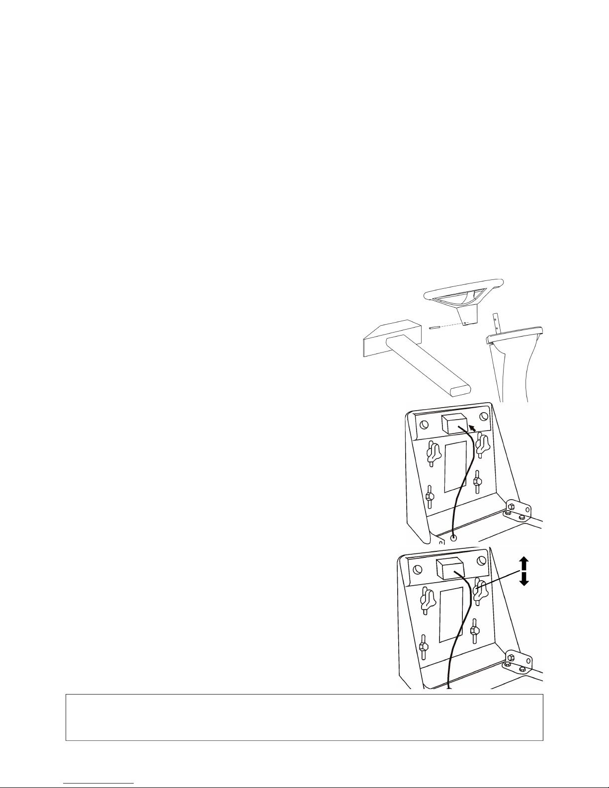
96
4. DEBALLAGE
La faucheuse automotrice est livrée dans un emballage en lattes. Pour des raisons de transport, certains groupes de la machine
sont désassemblés dans l'usine de construction et seront montés avant la mise en service. Le déballage et la préparation au service
sont effectués par le vendeur dans la cadre du service avant-vente.
4.1 CONTROLE APRES LE DEBALLAGE
Aprčs avoir enlevé l'emballage, descendez avec prudence la machine de la palette – utilisez des rampes d'accčs - autrement la
machine risque de s'endommager. Vérifi ez la machine si elle n'a pas étée endommagée pendant le transport. Déballez aussi touts
les groupes non-montés et vérifi ez les.
Dans l'emballage de base sont livrés:
• la faucheuse
• le volant
• le sičge
• la documentation (liste d'expédition, Mode d'emploi de la faucheuse, Mode d'emploi du moteur, Notice pour l'accumulateur,
Carnet d'entretien)
4.1.1 LIQUIDATION DE L'EMBALLAGE
Aprčs avoir déballé la machine, il faut procéder ŕ la liquidation de l'emballage. Effectuez la liquidation conformément avec la loi
correspondante. La séparation de l'emballage selon le matériel doit ętre effectuée suivant le catalogue d'emballages correspondant.
Cette opération peut ętre confi ée ŕ une fi rme spécialisée.
4.2 PREPARATION POUR LA MISE EN SERVICE
Compte tenu du caractčre technique de cette opération, la préparation de la mise en service de la faucheuse est effectuée par votre
vendeur (suivant le instructions du constructeur).
4.2.1 MONTAGE DU VOLANT
Placez la faucheuse sur une surface plane et redressez les roues arričre en sens
direct.
Ajustez le volant et verrouillez le dans l'ouverture correspondante ŕ l'hauteur de
la position choisie par la goupille fournie.
4.2.2 MONTAGE DU SIEGE
Enlevez l'emballage de protection du sičge. Apposez le sičge ŕ sa place sur la machine et
fi xez le ŕ l'aide des vis ainsi qu'ils sont prémontés dans le sičge.
4.2.3 AJUSTAGE DE LA POSITION DU SIEGE
Procédez de la maničre suivante pour positionner le sičge:
Desserrez les vis au rosettes en matičre plastique. Déplacez le sičge en avant ou en
arričre dans la position souhaitée. Reserrez fortement les vis au rosettes en matičre
plastique.
4.2.4 RACCORDEMENT DE L'ACCUMULATEUR
Lors de la mise en service de l'accumulateur procédez suivant les instructions indiquées
dans la Notice de l'accumulateur. L'accumulateur est situé dans la partie droite prčs
de la colonne du sičge sous le capot du moteur. Desserrez les vis aux sorties polaires
de l'accumulateur. Apposez le conducteur rouge au pôle “+” de l'accumulateur et
verrouillez le par le vis. Apposez le conducteur marron au pôle “-” de l'accumulateur
et verrouillez le par le vis.
AVERTISSEMENT
Un raccordement contraire au celui indiqué ci-dessus a pour conséquence l'endommagement de la machine.
Lors du débranchement de l'accumulateur, débrancher toujours comme premier le pôle “–” de l'accumulateur.
Respectez les consignes de maintenance indiquées dans la Notice de l'accumulateur.
Page 99
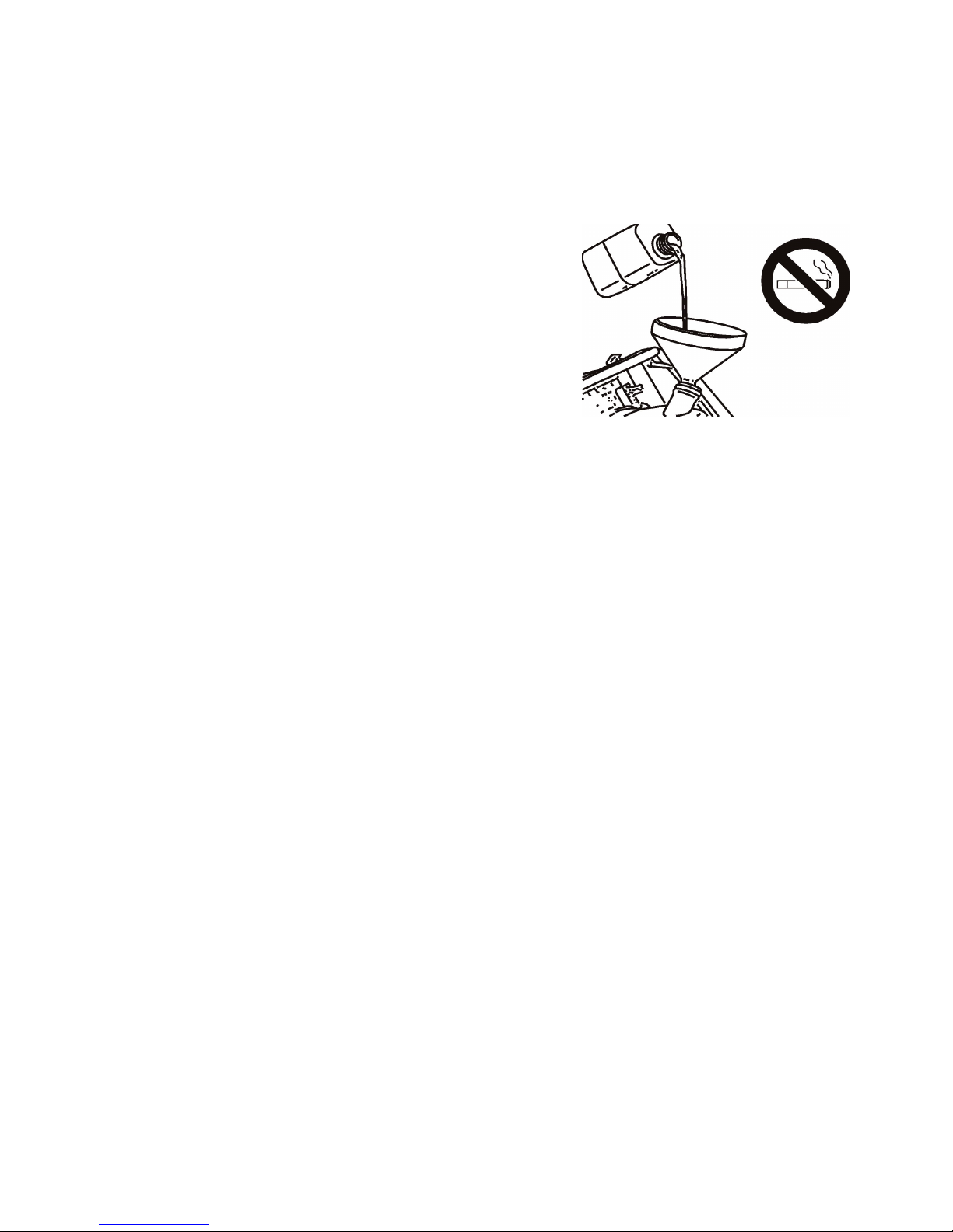
97
5. MISE EN MARCHE
Compte tenu du caractčre technique de cette opération, la mise en service de la faucheuse est effectuée par votre vendeur (suivant
le instructions du constructeur).
5.1 CONTROLE DU NIVEAU D'HUILE DANS LE MOTEUR
Procédez suivant le Mode d'emploi du moteur, respectez les instructions indiquées dans le chapitre 7.1 "Abrégé du contrôle et
de la maintenance".
5.2 CONTROLE DE L'ACCUMULATEUR
Effectuez suivant la Notice de l'accumulateur.
5.3 REMPLISSAGE DU RESERVOIR PAR DE
L'ESSENCE
• La machine est transportée sans carburant pour des raisons de sécurité.
• Effectuez le remplissage du réservoir uniquement quand le moteur est arręté
et froid.
• Utilisez uniquement de l'essence ŕ indice d'octane 95.
• Le réservoir est situé dans la colonne du sičge et est facilement accessible en
soulevant le sičge vers l'avant.
• Ouvrez doucement le bouchon du réservoir, car les vapeurs d’essence
peuvent causer une surpression ŕ l'intérieur de celui-ci.
• Lors du remplissage du carburant utilisez un jerrycan avec un entonnoir, ne
surchargez pas le réservoir.
• Il est possible de suivre ŕ l'oeil l'hauteur du niveau d'essence dans le réservoir
par la découpure dans la partie gauche de la colonne du sičge.
• Essuyez ŕ sec les abords du réservoir et le bouchon. Nettoyez réguličrement
aussi le réservoir entier, car les éventuelles impuretés dans l'essence peuvent
entraîner une panne.
• Lors de la manipulation avec le carburant, ne mangez pas, ne fumez pas et
n'utilisez pas de feu nu.
Page 100
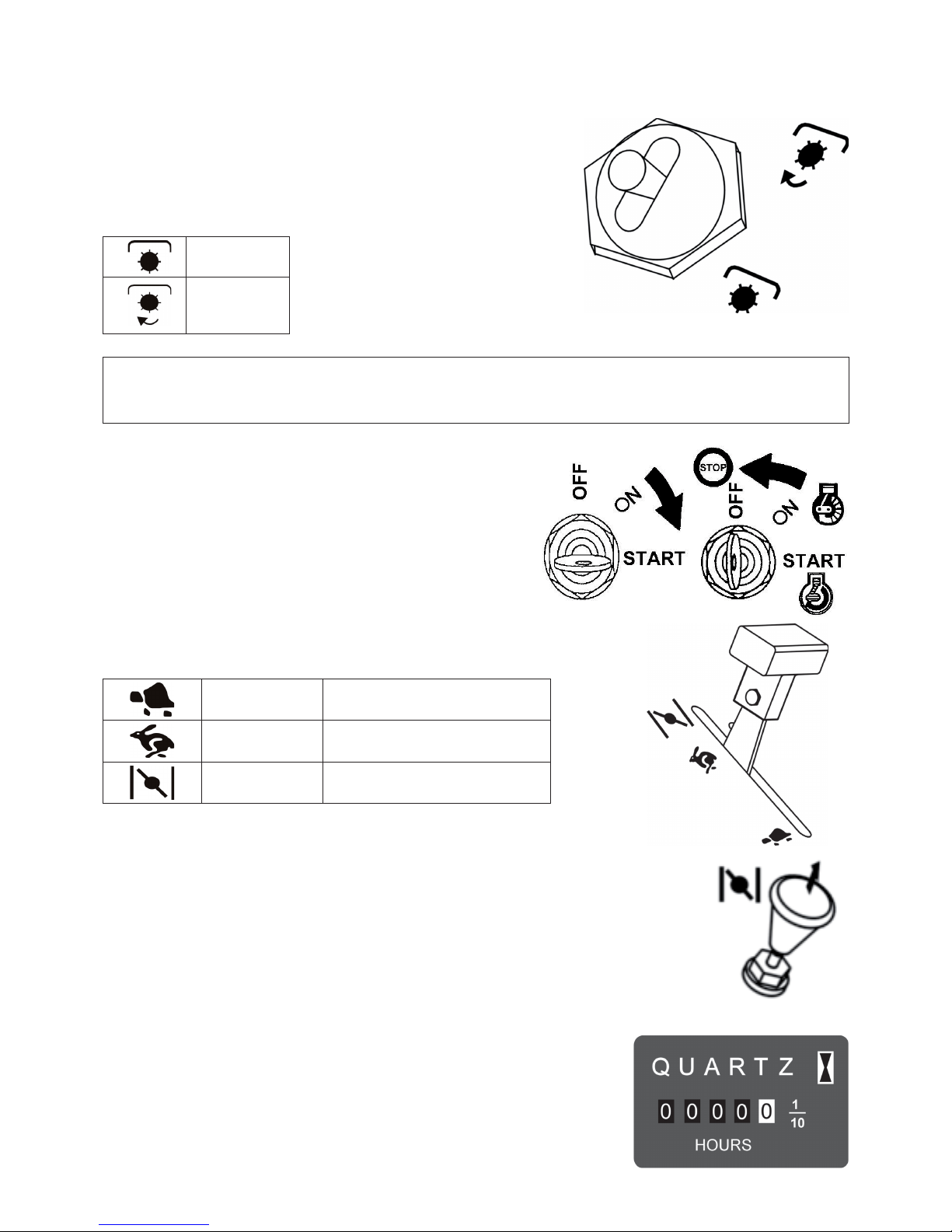
98
6. MANOEUVRE DE LA MACHINE
6.1 DESCRIPTION ET FONCTION DES MANIPULATEURS
6.1.1 INTERRUPTEUR DU DISPOSITIF DE COUPE
L'interrupteur du dispositif de coupe enclenche l'embrayage électromagnétique
dont la poulie ŕ courroie transmet par une courroie cunéiforme la traction du
moteur ŕ la poulie ŕ courroie du dispositif de coupe. L'interrupteur est en position
“arręté” assuré contre un enclenchement indésirable. Pour enclencher, il est
nécessaire de remonter un peu la manette de l'interrupteur et de la basculer en
position "allumé".
ARRETE
ALLUME
AVERTISSEMENT:
Si le dispositif de coupe est levé en position de transport (voir chap. 6.1.6), il est impossible d'enclencher
la traction du dispositif de coupe.
La position de transport est gardée par l'interrupteur de sécurité.
6.1.2 BOITE DE CONNEXION
La clef de contact a 3 positions:
OFF - allumage arręté
ON - allumage allumé
START - mise en marche du moteur
6.1.3 MANETTE DE GAZ
Elle régle le régime du moteur, ses différentes positions sont:
(fi gure de 6.1.3)
MIN régime de ralenti du moteur
MAX régime maximal du moteur
SATURATEUR * démarrage du moteur ŕ froid
* Le saturateur est installé sur la machine en fonction du type du moteur.
6.1.4 SATURATEUR
Permet le démarrage du moteur ŕ froid. Est installé sur la machine en fonction du type du
moteur.
6.1.5 COMPTEUR HORAIRE
Le compteur horaire est installé en fonction du type de la machine. Il est en action
seulement quand l'allumage est mis sous tension et quand le commutateur du sičge est
fermé (automatiquement par le poids de l'opérateur).
La manipulation avec le compteur représente une perte de la garantie. Toute panne du
compteur doit ętre immédiatement signalée ŕ votre service aprčs-vente.
 Loading...