

Page 1
TANGO
24
User’s Guide
Tango24, Dakota, Montana, Sierra, and Zulu are trademarks
of Frontier Design Group, LLC.
All other trademarks and registered trademarks
are the property of their respective holders.
Copyright © 1998-1999 Frontier Design Group, LLC
199 Heater Road • Lebanon, NH 03766 • 603-448-6283
All Rights Reserved
Page 2

Contents
Introduction....................................................1
About the Company.....................................1
Technical Support........................................ 2
Setting Up ................................................... 3
Front Panel .................................................... 4
Back Panel...................................................... 6
Theory of Operation..................................... 8
Tango24 Block Diagram .............................. 9
Tango24 Options .........................................10
Clock Source Selection ................................10
Changing Input and Output Levels .............15
Troubleshooting ...........................................16
Problems and Solutions ..............................16
Quick Global Test....................................... 18
Tango Specifications.....................................19
Page 3
Introduction
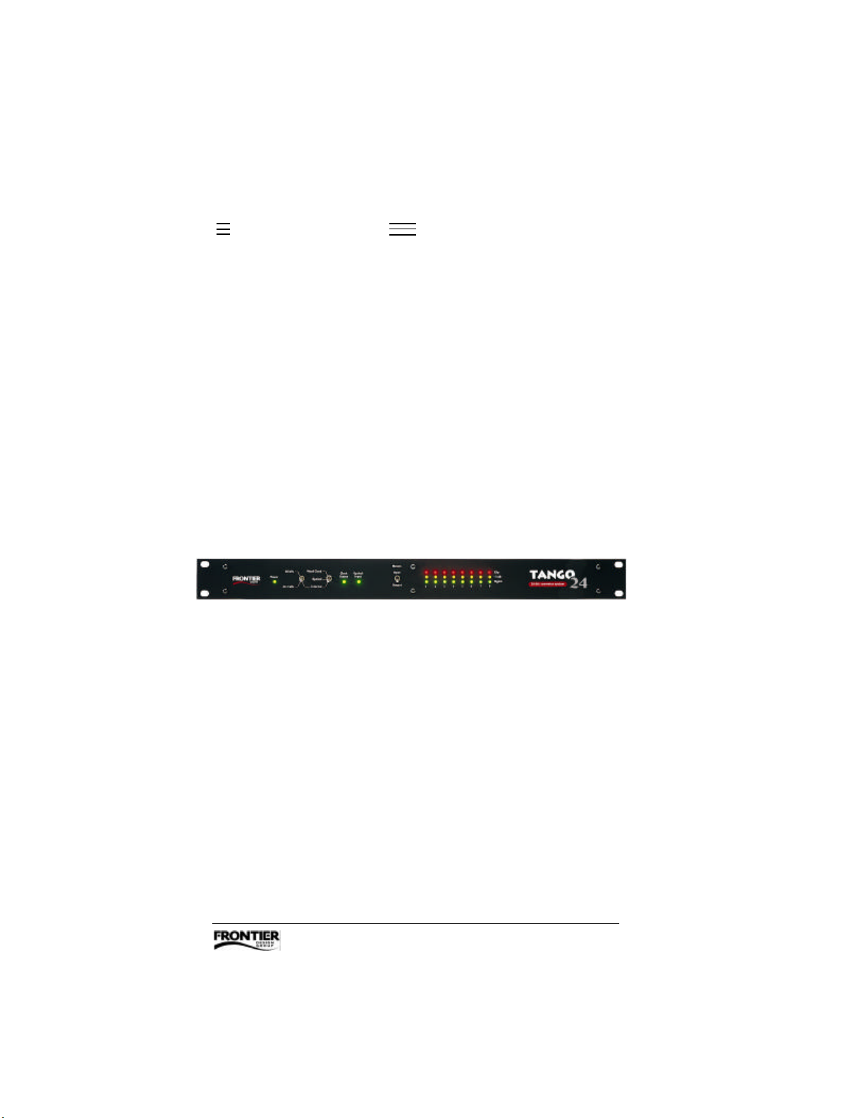
Tango24™ is a high-resolution, multichannel A/D and D/A converter
for computer-based systems. Its features include:
• ADAT™ optical digital interface (in/thru/out) and an external power
supply, which provide isolation from electrically-induced computer
noise
• 8 analog inputs and 8 analog outputs with 24-bit resolution
• balanced TRS connectors which can be individually set to
+4dBu or -10dBV levels (factory setting is +4dBu)
• LED meters indicating signal level, -3dB, and clipping on either the
inputs or the outputs
• word clock I/O for synchronizing to other digital audio gear
• rugged 1U rackmount enclosure
About the Company
Frontier Design Group develops, manufactures and sells digital audio
hardware and software. Our goal is to provide high-quality, high-value
tools to help our customers be more creative and productive.
We’re always interested in receiving your feedback on our products, as
well as your ideas for improvements and new products. You can send
e-mail to [email protected] or write to us at
199 Heater Road, Lebanon, NH 03766.
Tango24 User’s Guide 1
Page 4

Technical Support
If you have any problems or questions that aren’t addressed in this
Guide, there are three ways to get more help:
• Refer to our web site (http://www.FrontierDesign.com) for information
on current revisions, answers to frequently asked questions,
troubleshooting procedures, and additional documentation.
The web site is available every day, 24 hours a day.
• Send specific questions via e-mail to [email protected].
We’ll respond promptly (usually within one business day).
• For time-critical questions, you can call Frontier Design Group at
1-800-928-3236 (outside the USA, call 603-448-6283). Phone
support is normally provided weekdays from 9:30 am to 5:30 pm EST.
2 Tango24 User’s Guide
Page 5
Setting Up
In addition to this Guide, your Tango24 package should contain:
• Tango24 multichannel converter box
• AC power adapter
WARNING! Before you connect the AC power adapter, verify
that its prong style and input voltage rating are appropriate for
your local AC power source.
1. You can install Tango24 in a standard 19" rack.
2. Attach analog cables to the appropriate inputs and outputs on
Tango24’s back panel. Since inputs and outputs use the same type of
connectors, be careful to always connect from an output on one device
to an input on another device.
3. Connect optical cables from the ADAT ports of another device (such as
our WaveCenter ISA card or Dakota PCI card) to Tango24’s ADAT input
and output, making sure that you connect from an output to an input.
Note: The direction of an optical signal is easy to verify because
optical outputs emit red light. The outputs use light-emitting diodes
(LEDs), not laser light, so their light is not dangerous.
4. Connect the barrel plug of the AC power adapter to the Power input on
Tango24’s back panel, and connect the AC adapter to an acceptable
power outlet. If the power outlet is active, all the indicators on
Tango24’s front panel should blink, and then the Power indicator
should remain on.
5. Set the clock source switches on Tango24’s front panel to the
appropriate settings for your system. For details and illustrations, see
“Clock Source Selection” later in this Guide.
Note: At the factory, Tango24 is set for +4dBu input and output
levels. If you want to change any of the levels to -10dBV, see
“Changing Input and Output Levels” later in this Guide.
Tango24 User’s Guide 3
Page 6
Front Panel
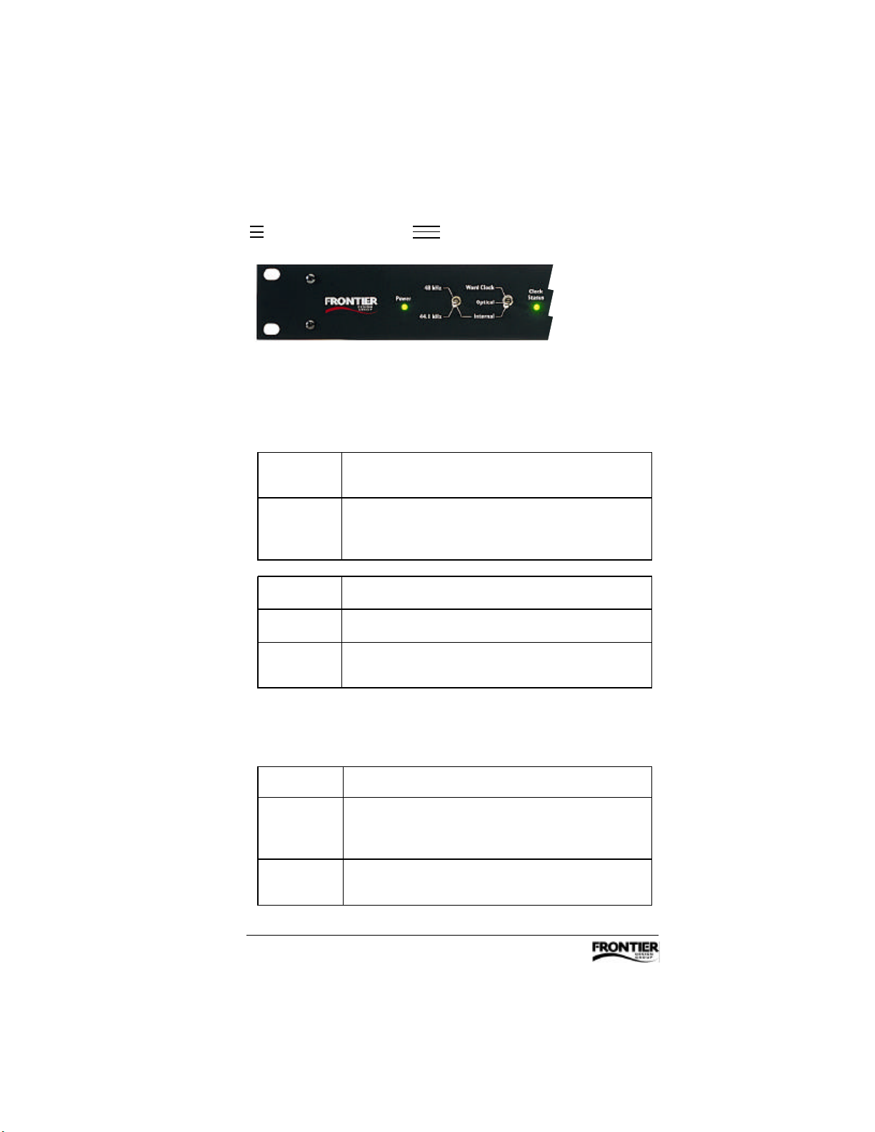
Power Indicator — Lights green when Tango24’s power is on.
Clock Source Switches
48kHz If the adjacent switch is set to “Internal,” the converters are
clocked from Tango24’s crystal-controlled 48kHz oscillator.
44.1kHz If the adjacent switch is set to “Internal,” the converters are
clocked from Tango24’s crystal-controlled 44.1kHz
oscillator.
Word Clock Tango24’s clock system follows the Word Clock input.
Optical Tango24’s clock system follows the ADAT optical input.
Internal Tango24 uses an internal crystal clock source whose
frequency is selected by the adjacent (48/44.1) switch.
Clock Status Indicator
Shows the status of the currently selected clock source.
on The clock is stable.
blinking An external clock source is selected, but either its sample
rate is outside of Tango24’s lock range or it has other
errors such as incorrect formatting.
off An external clock source is selected, but there is no signal at
that input.
4 Tango24 User’s Guide
Page 7
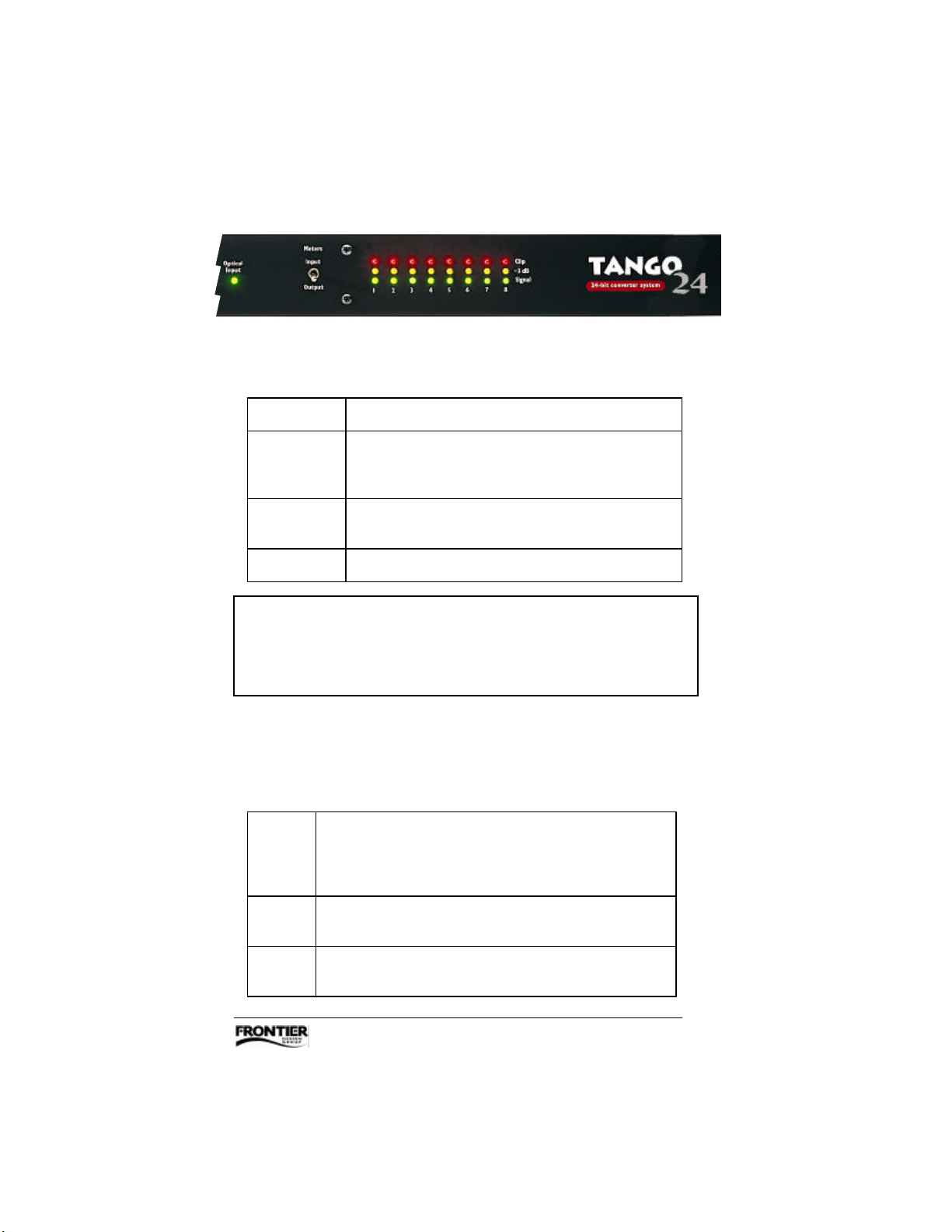
Optical Input Indicator
Shows the status of the ADAT optical input signal.
on The optical input is valid and locked to the clock system.
slow blinking The optical input is valid, but is not locked to the Tango24
clock system (Tango24’s optical input is based on a different
clock source and is “slipping”).
fast blinking The optical input has errors (either the data stream contains
errors or it is not ADAT optical format data – see note).
off There is no active optical input.
Note: Although TOSLINK connections from DAT machines, CD
players and other devices fit into the ADAT optical connectors
physically, their 2-channel SPDIF format is logically incompatible
with the 8-channel ADAT optical format used by Tango24.
Meters Switch — Selects whether the meter indicators show signal
levels for input channels or output channels.
Meter Indicators
red Clip – the signal is within 0.002dB of full scale. (When metering
outputs, clip indicators remain on for about half a second. When
metering inputs, clip indicators remain on until you reset them by
toggling the Meters Switch to Output and then back to Input.)
yellow -3dB – the signal is within 3dB of full scale.
(This indicator remains on for about half a second.)
green Signal – the intensity of this indicator varies in proportion
to signal strength.
Tango24 User’s Guide 5
Page 8
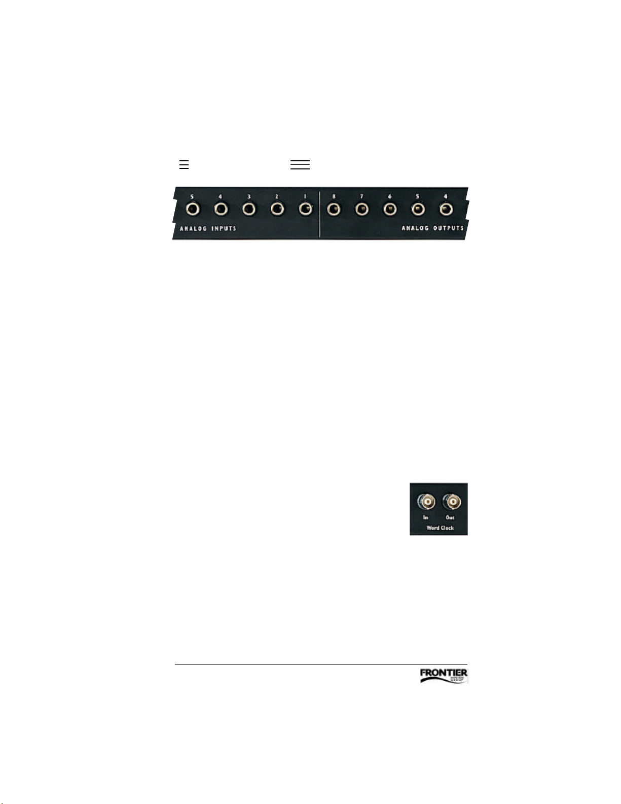
Back Panel
Analog I/O
The Tango24 converter box has 8 analog inputs and 8 analog outputs.
Each can accept balanced ¼" TRS (tip/ring/sleeve) plugs which have
three metal bands for the three wires (hot/cold/ground) in a balanced
audio connection, and are physically identical to ¼" stereo plugs.
Tango24 can also be used with ¼" mono plugs which have only two
metal bands, but this is an unbalanced connection which can pick up
more noise than a balanced connection.
Individual jumpers inside Tango24 let you set the reference level to
either +4dBu or -10dBV for each input and output independently. For
more details, see “Changing Input and Output Levels” later in this
Guide.
Word Clock I/O
The Word Clock Input can be used as Tango24’s clock
source when selected by the clock source switches on
Tango24’s front panel.
The Word Clock Output is always driven by Tango24’s
clock system at a frequency equal to the sample rate. For word clock
I/O, be sure to use coaxial 75-ohm video cables with BNC connectors.
6 Tango24 User’s Guide
Page 9
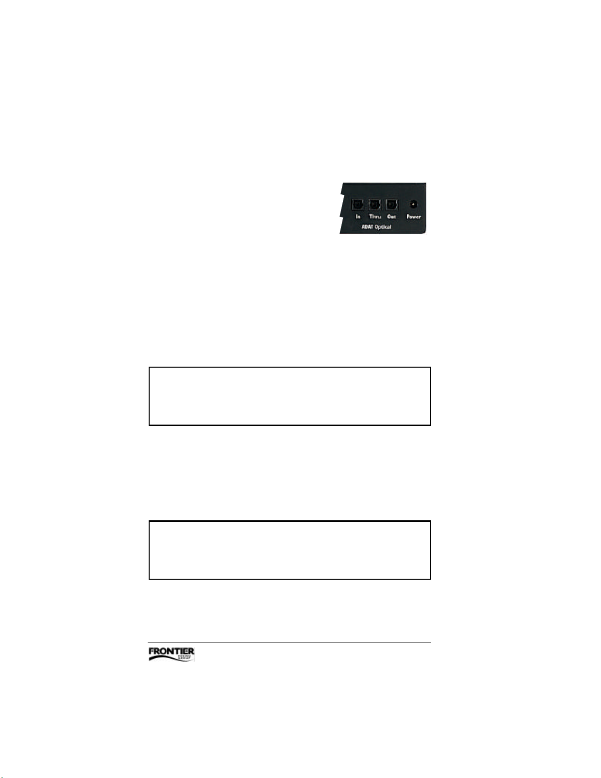
Optical I/O
The Optical Input receives audio data in
ADAT optical format which is converted to 8
channels of analog output.
The Optical Thru port simply transmits a copy of the optical input data.
By connecting the Optical Thru port to an ADAT machine, you can
archive 8 tracks of audio to ADAT tape without recabling. Since the
Optical Thru port acts as a repeater, you can also use it to send digital
audio data twice as far as a single optical cable can reach.
The Optical Output transmits audio data from Tango24’s A/D
converters.
Note: If the optical ports or the ends of your optical cables
have protective plastic covers, you’ll need to remove the
covers before connecting the cables.
Power
The Power jack is a barrel connector that receives power from
Tango24’s external AC power adapter.
WARNING! Use only a power adapter approved for Tango24
by Frontier Design Group. Using an unapproved power
adapter will void all warranties and may harm Tango24’s
Tango24 User’s Guide 7
Page 10

Theory of Operation
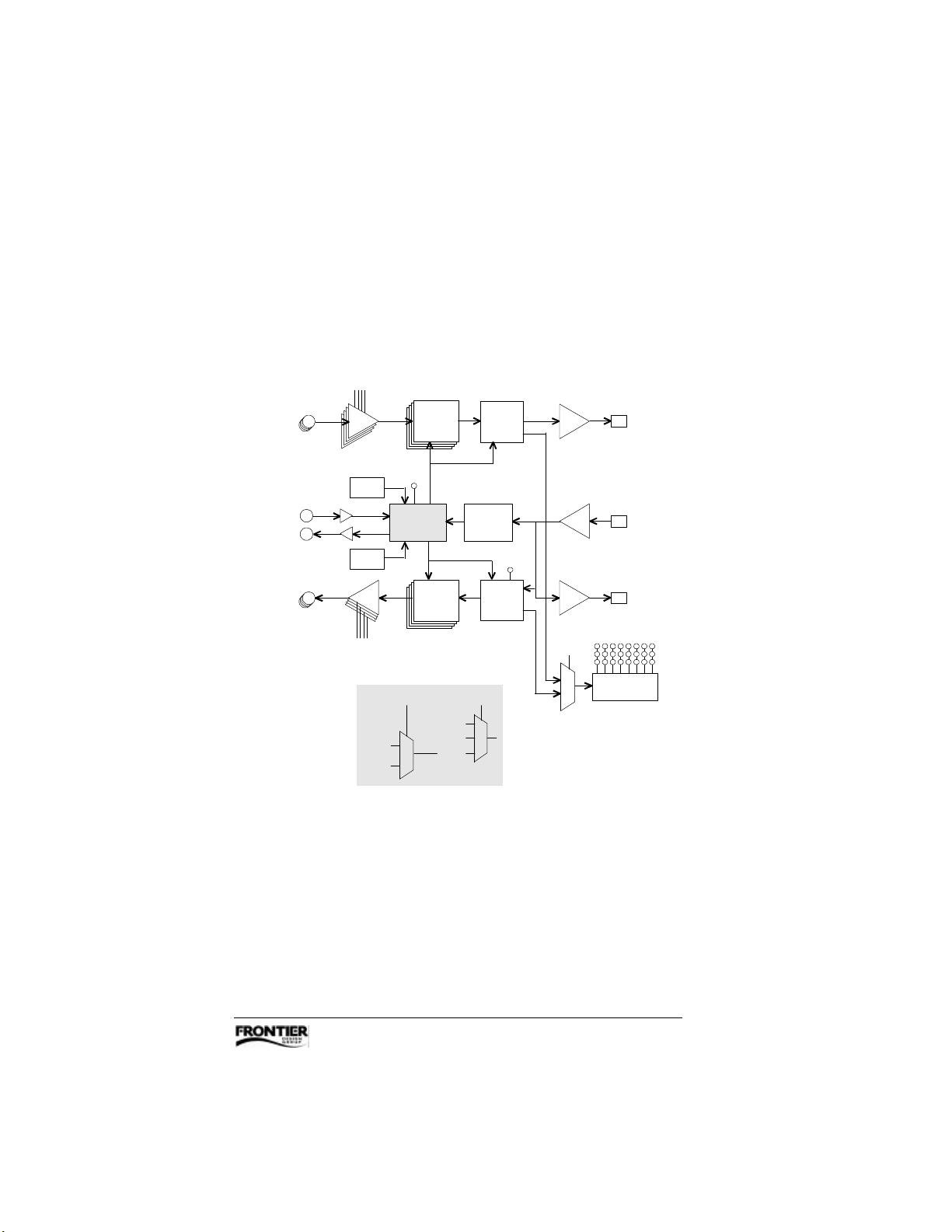
Tango24 has 8 channels of analog-to-digital (A/D) conversion and
8 channels of digital-to-analog (D/A) conversion. The reference level
for each analog input and output channel can be individually set to
either +4dBu or -10dBV. For instructions, see “Changing Input and
Output Levels” later in this Guide.
All the converters share a common sample clock along with the ADAT
encoder, ADAT decoder, and word clock transmitter. This sample clock
can come from internal crystal oscillators (44.1 or 48 kHz), from the
word clock input, or from the ADAT optical input.
Digital audio data from the A/D converters is combined and encoded
into ADAT format and is sent to the ADAT optical output.
The ADAT decoder reads 8 channels of audio and a sample clock from
the ADAT optical input. As this data is sent to the D/A converters, it will
be muted if —
• the ADAT decoder detects errors
• the ADAT optical input is not sample-locked to
the Tango24 clock system
• the clock source is an inactive or out-of-range word clock input
8 Tango24 User’s Guide
Page 11
Tango24 Block Diagram
+4dBu/-10dBV
input level selectors
8
analog
inputs
word clock
8
analog
outputs
OUT
IN
48kHz
oscillator
44.1kHz
oscillator
+4dBu/-10dBV
output level selectors
*
48kHz
44.1kHz
A/D
converter
Clock Status
indicator
clock
*
selection
recovery
D/A
converter
clock selection switches
word clock
optical
internal
ADAT
encoder
clock
Optical Input
ADAT
decoder
indicator
Meters
Input/Output
switch
(transmitter)
(receiver)
(transmitter)
generation
ADAT
optical
OUT
IN
THRU
meter
Tango24 User’s Guide 9
Page 12
Tango24 Options
Tango24’s front panel includes clock source switches that let you
specify the sample rate of your digital audio system. Tango24 also has
internal jumpers that let you set the analog input/output levels to
+4dBu or -10dBV.
Clock Source Selection
Every digital audio system operates at a particular sample rate, such
as 44,100 samples per second (44.1kHz) for CDs. Tango24 has
internal crystal oscillators that support the standard sample rates of
44.1kHz and 48kHz.
When two or more digital audio devices transfer data, one and only
one of them should be used to set the sample rate. This device is
called the sync source or the sample clock master, and it uses an
internal oscillator to set the sample rate. All other devices must be
synchronized (slaved) to the sample clock master. (Note: This
discussion is referring to sample rate synchronization, not timecode
synchronization.)
No two oscillators run at exactly the same rate, even if they’re both
44.1kHz oscillators (for example). Therefore, if two devices in one
system are both using their own internal oscillators, one is inevitably
faster than the other. As a result, samples are lost or duplicated
during the transfer. When multiple sample rates are detected, some
devices mute, some generate clicks and pops, and some exhibit
completely erratic behavior.
REMEMBER! Any digital audio system must always have
one and only one sync source, which should determine the
sample rate for all devices in that system.
10 Tango24 User’s Guide
Page 13
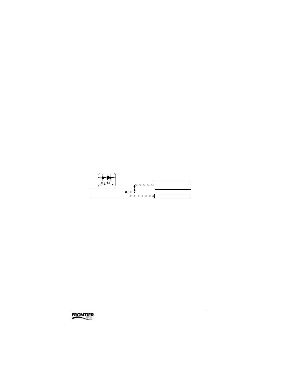
For example, consider a DAT machine connected via SPDIF to a Dakota
digital audio soundcard that’s connected to Tango24.
Most DAT machines must be the sync source when they’re playing.
Therefore, if you want to play from a DAT tape through Dakota and
listen to the audio in real time through Tango24 —
• the DAT machine’s sync (or clock) is set to “Internal” by default
• set the Dakota clock source to “Dig In SPDIF” (so it is slaved to the
DAT’s sample rate)
• set Tango24’s clock source switch to “Optical” (so it is slaved to
Dakota’s sample rate which is in turn slaved to the DAT)
SPDIF coax
OUT
SPDIF coax
computer with
DAKOTA
Clock Source: Dig In SPDIF clock source: Optical
IN
audio + sync
DAT
(internal sync)
TANGO
24
The following illustrations show some synchronization settings that
work well, and two examples that don’t work. In each usable system,
exactly one device is set to “Internal” sync, and all other devices
receive sync signals from that device.
Tango24 User’s Guide 11
Page 14
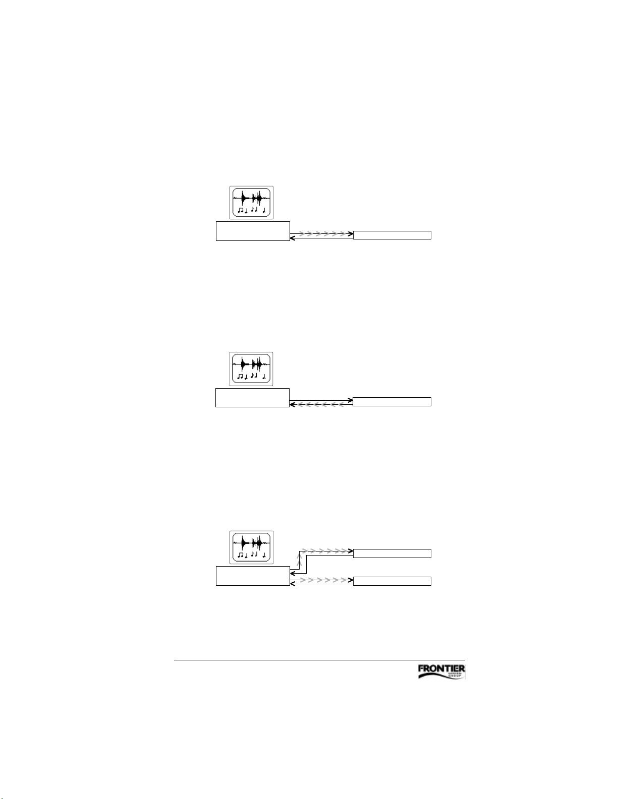
Example 1: Dakota is the master; Tango24 is slaved to Dakota.
computer with
DAKOTA
Clock Source: Internal clock source: Optical
audio + sync
audio
TANGO
24
Example 2: Tango24 is the master; Dakota is slaved to Tango24.
computer with
DAKOTA
Clock Source: Dig In Opt A clock source: Internal 44.1 or 48 kHz
audio
audio + sync
TANGO
24
Example 3: Dakota is the master;
Tango24 A and Tango24 B are slaved to Dakota.
audio + sync
audio
computer with
DAKOTA
Clock Source: Internal clock source: Optical
audio + sync
audio
12 Tango24 User’s Guide
clock source: Optical
TANGO24A
TANGO
B
24
Page 15
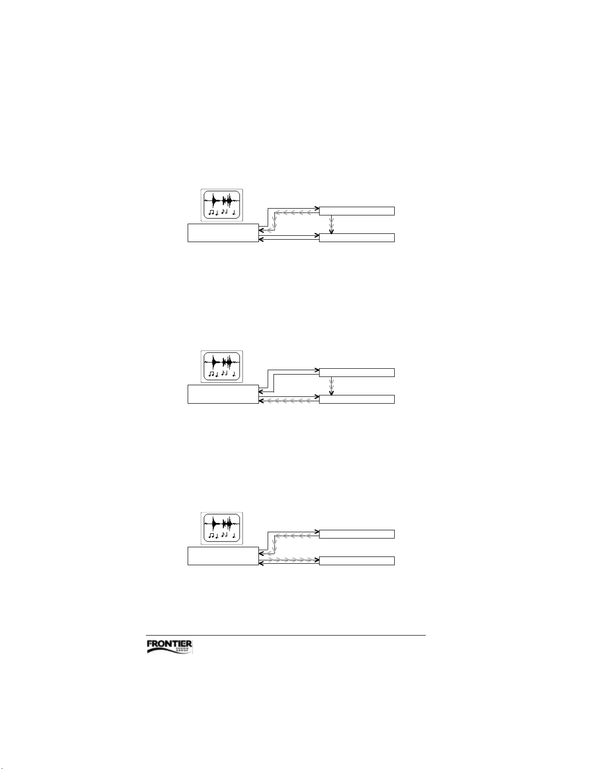
Example 4: Tango24 A is the master;
Dakota and Tango24 B are slaved to Tango24 A.
clock source: Internal 44.1 or 48 kHz
audio
audio + sync
computer with
DAKOTA
Clock Source: Dig In Opt A clock source: Word Clock
audio
audio
OUT
word clock + sync
IN
TANGO
TANGO
A
24
B
24
Example 5: Tango24 A is the master;
Tango24 B is slaved to Tango24 A, and Dakota is slaved to Tango24 B.
clock source: Internal 44.1 or 48 kHz
audio
audio
computer with
DAKOTA
Clock Source: Dig In Opt B clock source: Word Clock
audio
audio + sync
OUT
word clock + sync
IN
TANGO
TANGO24B
A
24
Example 6: Tango24 A is the master;
Dakota is slaved to Tango24 A, and Tango24 B is slaved to Dakota.
clock source: Internal 44.1 or 48 kHz
audio
audio + sync
computer with
DAKOTA
Clock Source: Dig In Opt A clock source: Optical
audio + sync
audio
TANGO
TANGO24B
A
24
Tango24 User’s Guide 13
Page 16
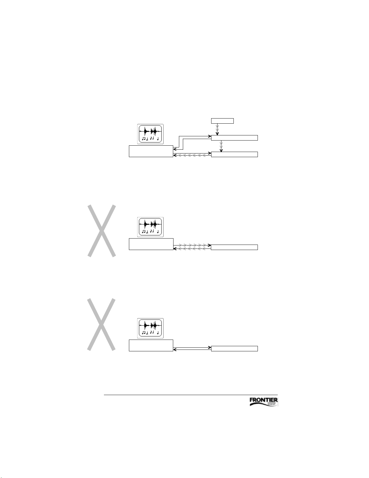
Example 7: The BRC is the master; Tango24 A is slaved to the BRC,
Clock Source: Internal
clock source: Internal 44.1 or 48 kHz
Tango24 B is slaved to Tango24 A, and Dakota is slaved to Tango24 B.
BRC
OUT
word clock
+ sync
audio
audio
computer with
DAKOTA
Sync: External (Slave) clock source: Word Clock
audio
audio + sync
clock source: Word Clock
IN
TANGO24A
OUT
word clock
+ sync
IN
TANGO
B
24
Example 8: This example does NOT work because
both devices are set to “Internal” (there are too many masters).
computer with
DAKOTA
audio + sync
audio + sync
TANGO
24
Example 9: This example does NOT work because
each device expects sync signals from the other device (there is no master).
computer with
DAKOTA
Clock Source: Dig In Opt A clock source: Optical
audio
audio
TANGO
24
14 Tango24 User’s Guide
Page 17
Changing Input and Output Levels
You can select a +4dBu or -10dBV reference level for each of
Tango24’s analog inputs and outputs. The factory setting is +4dBu.
Most “professional” balanced I/O gear uses +4dBu levels; most
unbalanced I/O gear uses -10dBV levels.
To adjust the reference level for any input or output, you change a
jumper inside the Tango24 box. You’ll need a small crosshead
screwdriver (Phillips or Pozi-drive) and a clean, smooth work surface.
WARNING! Before opening the Tango24 box, disconnect all of
its cables — especially the power cable. To protect Tango24’s
electronic components, always touch the metal chassis before
touching the jumper or circuit boards.
1. Place Tango24 on a clean, smooth work surface and disconnect the
power supply.
2. Remove the 9 screws from the top cover, and remove the screw at the
top middle of Tango24’s front panel.
3. Remove the top cover, and set it aside.
4. Locate the 3-pin header near the appropriate analog input or output
jack(s). Each header should have a black plastic jumper covering two
of the header pins. Labels on the circuit board indicate the channel
numbers and reference level positions.
5. For a -10dBV level, lift the jumper and place it over the two header
pins nearest Tango24’s back panel. For a +4dBu level, lift the jumper
and place it over the two header pins nearest Tango24’s front panel.
6. Replace Tango24’s cover and all 10 screws before reconnecting the
power supply.
Tango24 User’s Guide 15
Page 18
Troubleshooting
This section describes some possible problems, and some suggestions
for resolving them. It also includes a “Quick Global Test” that lets you
quickly test almost all of Tango24’s functions.
Problems Make sure the answer to each question is “yes”
Power light
is off
Optical Input
light is off
Optical Input
light is blinking
rapidly (several
times a second)
Optical Input
light is blinking
slowly (less
than two times
a second)
Analog outputs
are clipping
Is the AC adapter properly connected to an AC power source
and to Tango24’s power input?
If the AC adapter is connected to a power strip, is the strip on?
Is Tango24’s Power indicator on?
Is there an optical cable plugged into Tango24’s optical input?
If you unplug the optical cable from Tango24’s optical input,
do you see red light emitting from the cable?
Is the source device currently sending audio data through the
optical cable?
Is the optical cable coming from a device that is transmitting
optical data in the 8-channel ADAT format rather than the
2-channel SPDIF (TOSLINK) format generated by a CD player
or DAT machine?
Is the optical input derived from the same sample clock source
as Tango24? If not, either set Tango24’s Clock Source switch
to “Optical” or change the clock source at the other end of the
optical input cable. Refer to “Clock Source Selection” earlier in
this Guide to see settings that work well.
Is the analog destination device expecting -10dBV levels?
If so, are Tango24’s analog outputs set to -10dBV reference
levels rather than +4dBu reference levels?
Analog outputs
are weak
Is the analog destination device expecting +4dBu levels?
If so, are Tango24’s analog outputs set to +4dBu reference
levels rather than -10dBV reference levels?
16 Tango24 User’s Guide
Page 19
Problems Make sure the answer to each question is “yes”
Analog outputs
are silent
Analog inputs
are clipping
Analog inputs
are weak
Can’t record
through
Tango24’s
analog inputs
Are Tango24’s analog outputs routed to a mixer–amplifier–
speaker system that is powered and has appropriate level
settings?
Is Tango24’s Optical Input indicator on, and not blinking?
Are there active audio tracks playing from the computer (or
other source device) on the correct ADAT optical output
channels?
With the Meters switch on Tango24’s front panel set to
“Output,” do the appropriate Analog Output indicators light up
in response to amplitude levels of the source audio?
Is the analog source device sending +4dBu levels? If so, are
Tango24’s analog inputs set to +4dBu reference levels rather
than -10dBV reference levels?
Is the analog source device sending -10dBV levels? If so, are
Tango24’s analog inputs set to -10dBV reference levels
rather than +4dBu reference levels?
Is Tango24’s Power indicator on?
Are there active analog signals routed to the appropriate
Tango24 inputs?
Is an optical cable properly connected to Tango24’s optical
output?
If Tango24 is set to an external clock source, is the Clock
Source indicator on and not blinking?
With the Meters switch on Tango24’s front panel set to
“Input,” do the appropriate Analog Input indicators light up in
response to amplitude levels of the source audio?
Is the computer (or other destination device) set up to record
the appropriate ADAT input channels?
Tango24 User’s Guide 17
Page 20

Quick Global Test
This loopback procedure tests almost all of Tango24’s functions, and
can be useful if you have doubts about whether Tango24 is working
properly.
1. Connect an active analog source to Tango24’s analog input 1.
2. Connect an optical cable from Tango24’s optical output to its
optical input.
3. Set Tango24’s clock source switch to “Internal”
–OR–
If you want to verify a word clock input, connect the appropriate
cable from a word clock source and set Tango24’s clock source switch
to “Word Clock.”
4. Make sure the power is on, and monitor Tango24’s analog output 1.
It should sound the same as analog input 1.
You can repeat this loopback test using other input/output pairs. The
output you’re monitoring should sound the same as the input, and
Tango24’s Optical Input indicator should be on and not blinking.
To test the Optical Thru port—
1. Set Tango24’s clock source switch to “Internal.”
2. Connect an optical cable from the Optical Thru port to the Optical In
port, and verify that the Optical Input indicator is on and not blinking.
18 Tango24 User’s Guide
Page 21

Tango24 Specifications
These specifications are typical measurements and are subject to revision
without notice.
A/D
Resolution
Frequency Response
THD+N (EIAJ)
S/N ratio (EIAJ)
Connector
Reference Level
Headroom
Impedance
Resolution
Frequency Response
THD+N (EIAJ)
S/N ratio (EIAJ)
Connector
Reference Level
Headroom
24 bits
±0.05dB, 20Hz–20kHz
0.002% A-weighted
105dB
balanced ¼" TRS phone jack
+4dBu or -10dBV, selectable per channel
15dB (maximum level 5dBV at -10dBV reference level,
or 19dBu at +4dBu reference level)
>15kΩ
D/A
24 bits
±0.05dB, 20Hz–20kHz
0.002% A-weighted
105dB
differentially balanced ¼" TRS phone jack
+4dBu or -10dBV, selectable per channel
15dB (maximum level 5dBV at -10dBV reference level,
or 19dBu at +4dBu reference level)
Other
Sample Rates
Clock Sources
ADAT Optical Ports
Word Clock Ports
Power Supply
Dissipation
Dimensions
Weight
39–51kHz from optical or word clock input
Internal (44.1 or 48 kHz), Word Clock, Optical Input
In, Thru, Out
In, Out
10–12VAC with 2.1mm x 5mm barrel jack connector
20W
19" x 8.5" x 1.75" (1U rackmount enclosure)
485mm x 215mm x 45mm
7.5 lbs (3.5 kg), including AC adapter
Tango24 User’s Guide 19
 Loading...