


OPERATOR’S MANUAL
4106
4109
OMUS00W41 (01/23/09)

INTRODUCTION
READ THIS MANUAL carefully to learn how to operate and service your machine correctly. Failure to do so
could result in personal injury or equipment damage.This manual and safety signs on your machine may also be
available in other languages. (See your Frontier dealer to order.)
THIS MANUAL SHOULD BE CONSIDERED a permanent part of your machine and should remain with the
machine when you sell it.
MEASUREMENTS in this manual are given in both metric and customary U.S. unit equivalents. Use only correct
replacement parts and fasteners. Metric and inch fasteners may require a specific metric or inch wrench.
RIGHT-HAND AND LEFT-HAND sides are determined by facing in the direction the implement will travel when
going forward.
WRITE PRODUCT IDENTIFICATION NUMBERS
(P.I.N.) in the Specification section. Accurately record all the numbers to help in tracing the machine should it be
stolen. Your dealer also needs these numbers when you order parts. File the identification numbers in a secure
place off the machine.
WARRANTY is provided as part of Frontier’s support program for customers who operate and maintain their
equipment as described in this manual.
This warranty provides you the assurance that Frontier will back its products where defects appear within the
warranty period. In some circumstances, Frontier also provides field improvements, often without charge to the
customer, even if the product is out of warranty. Should the equipment be abused, or modified to change its
performance beyond the original factory specifications, the warranty will become void and field improvements
may be denied. Setting fuel delivery above specifications or otherwise overpowering machines will result in such
action.
THE TIRE MANUFACTURER’S warranty applicable to your machine may not apply outside the U.S.
1

TABLE OF CONTENTS
Page
SAFETY 4
PREPARING THE TRACTOR
Positioning Tractor Drawbar 14
Using Drawbar Shield 14
Making Drawbar Shield 15
Three-Point Hitch Position 15
Checking Ballast, Wheel Spacing, and Tire Inflation 15
PREPARING THE RAKE
Checking Tire Inflation Pressure 16
Checking Wheel Nut Torque 16
ATTACHING AND DETACHING
Attaching Rake to Tractor Drawbar 17
Attaching to Tractor Hydraulic System 18
Detaching Rake from Tractor 19
TRANSPORTING
Preparing Rake For Transport 21
OPERATING THE RAKE
Prestarting Checks 24
Preparing Rake for Field Operation 24
Operating the Rake 26
Seting working Width 27
Adjusting Raking Wheel Height 28
Direction of travel 28
LUBRICATION AND MAINTENANCE
Perform Lubrication and Maintenance 29
Observe Lubrication Symbols 29
Alternative and Synthetic Lubricants 30
Grease 30
Lubricant Storage 31
Every 10 Hours 31
Every 50 Hours 32
Every 100 Hours 33
Annually 34
As Required 35
TROUBLESHOOTING 36-37
SERVICE
Servicing Tires Safely 38
2

TABLE OF CONTENTS
Servicing Rake Safely 38
Replacing Wheel Tines 39
STORAGE
End of Season 40
Beginning of Season 40
CHECKLISTS
Dealers Record 41
Predelivery 41
Delivery 42
ASSEMBLY
Install rake wheel frame 43
Install the ground wheels 44
Assembly frames 45
Assembly drawbar 46
Install hydraulic circuit 47
Assembly rake wheels 48
Install SMV Emblem 49
Install transport lights 50
FINAL INSPECTION AND LUBRICATION
Final Inspection and Lubrication 51
SPECIFICATIONS
High-Capacity Wheel Rake 52
Record Product Identification Number 53
Tightening Flare Type Tube Fittings 53
Unified Inch Bolt and Cap Screw Torque Values 54
Metric Bolt and Cap Screw Torque Values 55
SPARE PARTS 56-73
INDEX 74
3

SAFETY
SAFETY ALERT SYMBOL
Why is SAFETY important to you?
3 BIG REASONS · ACCIDENTS COST
This safety alert symbol indicates important safety messages in this
manual and on safety signs on the machine.
This symbol means:
ATTENTION!
BECOME ALERT!
YOUR SAFETY IS INVOLVED!
Carefully read and follow the safety message accompanying this symbol.
· ACCIDENTS DISABLE AND KILL
· ACCIDENTS CAN BE AVOIDED
SIGNAL WORDS
Note the use of the signal words DANGER, WARNING, and CAUTION with safety messages. The appropriate
signal word for each message has been selected using the following guidelines:
DANGER – Indicates an imminently hazardous situation that, if not avoided, will result in death or
serious injury.
WARNING – Indicates a potentially hazardous situation that, if not avoided, could result in death or
serious injury. It is also used to alert against unsafe practices.
CAUTION – Indicates a potentially hazardous situation that, if not avoided, may result in minor or
moderate injury. It is also used as a reminder of good safety practices.
4

SAFETY
FOLLOW SAFETY INSTRUCTIONS
Carefully read all safety messages in this manual and
on your machine safety signs. Keep safety signs in
good condition. Replace missing or damaged safety
signs. Be sure new equipment components and repair
parts include the current safety signs. Replacement
safety signs are available from your Frontier dealer.
Learn how to operate the machine and how to use
controls properly. Do not let anyone operate without
instruction.
Keep your machine in proper working condition.
Unauthorized modifications to the machine may impair
the function and/or safety and affect machine life.
If you do not understand any part of this manual and
need assistance, contact your Frontier dealer.
OPERATE RAKE SAFELY
All machinery should be operated by responsible
persons who have been properly instructed and
delegated to do so.
Before each use, inspect entire machine. Check
tightness of all hardware.
Stop the tractor engine and engage parking brake
before leaving tractor operator’s station to adjust,
lubricate, clean or unclog the machine.
Never hand feed material into the machine.
Do not lean against, sit, or stand on rake.
Make sure bystanders are clear of machine before
lowering rake wheels.
5
SAFETY
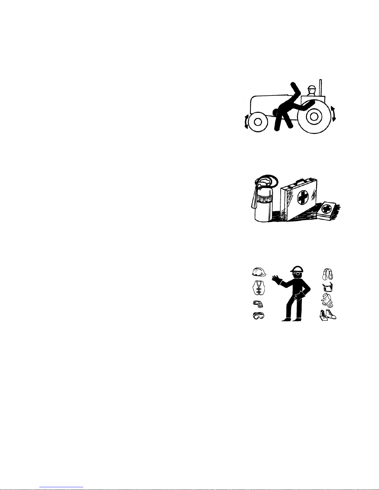
KEEP RIDERS OFF MACHINE
Only allow the operator on the machine. Keep riders off.
Riders on machine are subject to injury such as being
struck by foreign objects and being thrown off of the
machine. Riders also obstruct the operator’s view
resulting in the machine being operated in an unsafe
manner.
PREPARE FOR EMERGENCIES
Be prepared if a fire starts.
Keep a first aid kit and fire extinguisher handy.
Keep emergency numbers for doctors, ambulance
service, hospital, and fire department near your
telephone.
WEAR PROTECTIVE CLOTHING
Wear close fitting clothing and safety equipment
appropriate to the job.
Operating equipment safely requires the full attention of
the operator. Do not wear radio or music headphones
while operating machine.
6
SAFETY
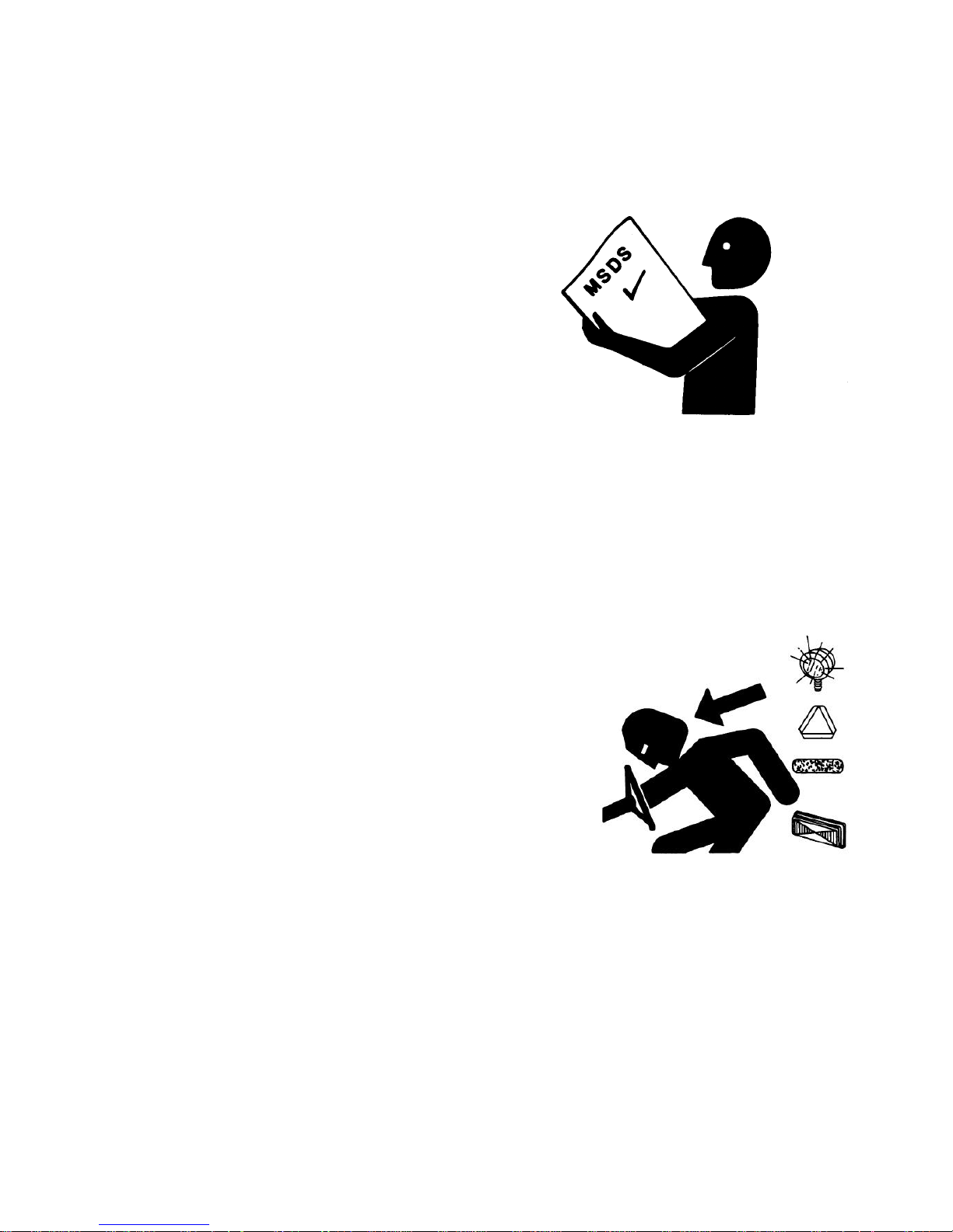
HANDLE CHEMICAL PRODUCTS SAFELY
Direct exposure to hazardous chemicals can cause
serious injury. Potentially hazardous chemicals used
with Frontier equipment include such items as
lubricants, coolants, paints, and adhesives.
A Material Safety Data Sheet (MSDS) provides specific
details on chemical products: physical and health
hazards, safety procedures, and emergency response
techniques.
Check the MSDS before you start any job using a
hazardous chemical. That way you will know exactly
what the risks are and how to do the job safely. Then
follow procedures and recommended equipment.
(See your Frontier dealer for MSDS’s on chemical
products used with Frontier equipment.)
USE SAFETY LIGHTS AND DEVICES
Prevent collisions between other road users, slow
moving tractors with attachments or towed equipment,
and self-propelled machines on public roads.
Frequently check for traffic from the rear, especially in
turns, and use hand signals or turn signal lights.
Use headlights, flashing warning lights, and turn signals
day and night. Follow local regulations for equipment
lighting and marking. Keep lighting and marking visible
and in good working order. Replace or repair lighting
and marking that has been damaged or lost.
7
SAFETY
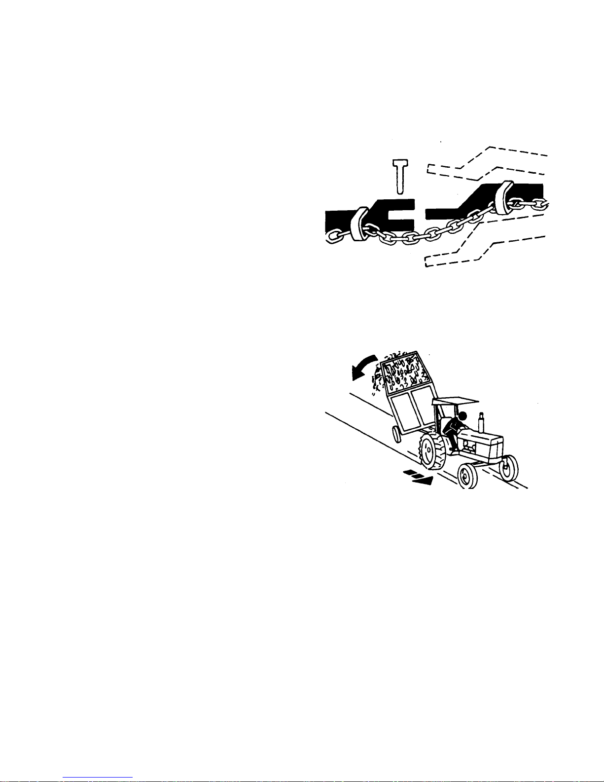
USE A SAFETY CHAIN
A safety chain will help control drawn equipment should
it accidentally separate from the drawbar.
Using the appropriate adapter parts, attach the chain to
the tractor drawbar support or other specified anchor
location. Provide only enough slack in the chain to
permit turning.
See your Frontier dealer for a chain with a strength
rating equal to or greater than the gross weight of the
towed machine. Do not use safety chain for towing.
TOW LOADS SAFELY
Stopping distance increases with speed and weight of
towed loads, and on slopes. Towed loads with or
without brakes that are too heavy for the tractor or are
towed too fast can cause loss of control. Consider the
total weight of the equipment and its load.
Observe these recommended maximum road speeds,
or local speed limits which may be lower:
• If towed equipment does not have brakes, do not
travel more than 32 km/h (20 mph) and do not tow
loads more than 1.5 times the tractor weight.
• If towed equipment has brakes, do not travel more
than 40 km/h (25 mph) and do not tow loads more
than 4.5 times the tractor weight.
Ensure the load does not exceed the recommended
weight ratio. Add ballast to recommended maximum for
tractor, lighten the load, or get a heavier towing unit.
The tractor must be heavy and powerful enough with
adequate braking power for the towed load. Use
additional caution when towing loads under adverse
surface conditions, when turning, and on inclines.
8

SAFETY
SERVICE RAKE SAFELY
To help prevent injury caused by unexpected
movement, be sure to service machine on level surface.
Lower rake wheels before servicing or adjusting rake.
If machine is connected to a tractor:
• Engage tractor parking brake and/or place
transmission in “Park.”
• Shut off engine and remove key.
If machine is detached from tractor, block wheels and
use safety stands to prevent movement.
To avoid eye injuries, cuts and bruises, take care when
working around raised wheels. Do not service or adjust
machine with rake wheels raised.
PRACTICE SAFE MAINTENANCE
Understand service procedure before doing work. Keep
area clean and dry.
Never lubricate, service, or adjust machine while it is
moving. Keep hands, feet, and clothing from powerdriven parts. Disengage all power and operate controls
to relieve pressure. Lower equipment to the ground.
Stop the engine. Remove the key. Allow machine to
cool.
Securely support any machine elements that must be
raised for service work.
Keep all parts in good condition and properly installed.
Fix damage immediately. Replace worn or broken parts.
Remove any buildup of grease, oil, or debris.
Disconnect battery ground cable (-) before making
adjustments on electrical systems or welding on
machine.
9
SAFETY
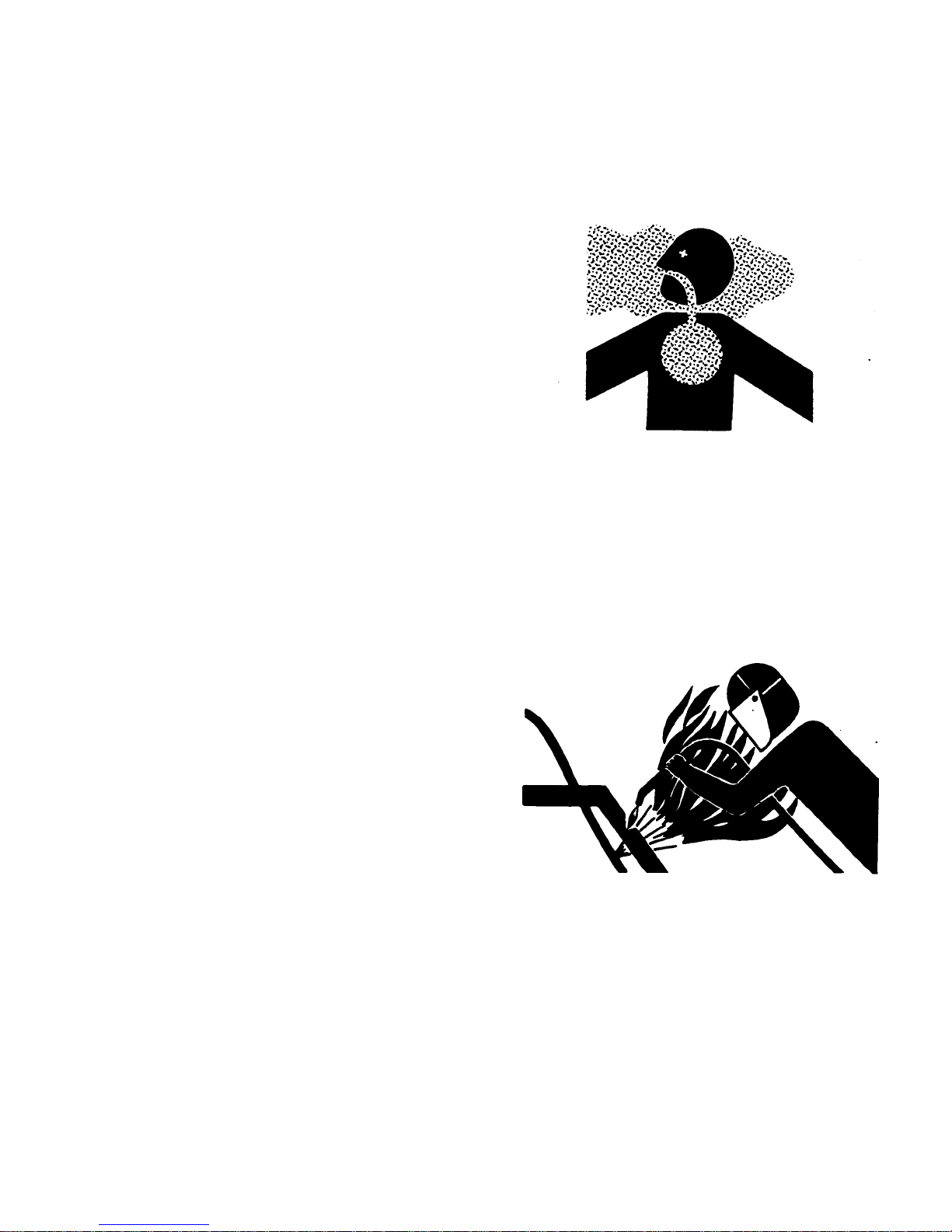
REMOVE PAINT BEFORE WELDING OR
HEATING
Avoid potentially toxic fumes and dust.
Hazardous fumes can be generated when paint is
heated by welding, soldering, or using a torch.
Do all work outside or in a well ventilated area. Dispose
of paint and solvent properly.
Remove paint before welding or heating:
• If you sand or grind paint, avoid breathing the dust.
Wear an approved respirator.
• If you use solvent or paint stripper, remove stripper
with soap and water before welding. Remove solvent or
paint stripper containers and other flammable material
from area. Allow fumes to disperse at least 15 minutes
before welding or heating.
AVOID HEATING NEAR PRESSURIZED
FLUID LINES
Flammable spray can be generated by heating near
pressurized fluid lines, resulting in severe burns to
yourself and bystanders. Do not heat by welding,
soldering, or using a torch near pressurized fluid lines
or other flammable materials. Pressurized lines can be
accidentally cut when heat goes beyond the immediate
flame area.
10

SAFETY
AVOID HIGH-PRESSURE FLUIDS
Escaping fluid under pressure can penetrate the skin
causing serious injury.
Avoid the hazard by relieving pressure before
disconnecting hydraulic or other lines. Tighten all
connections before apply pressure.
Search for leaks with a piece of cardboard. Protect
hands and body from high pressure fluids.
If an accident occurs, see a doctor immediately. Any
fluid injected into the skin must be surgically removed
within a few hours or gangrene may result. Doctors
unfamiliar with this type of injury should reference a
knowledgeable medical source. Such information is
available from Deere & Company Medical Department
in Moline Illinois, U.S.A.
STORE ATTACHMENTS SAFELY
Stored attachments such as dual wheels, cage wheels,
and loaders can fall and cause serious injury or death.
Securely store attachments and implements to prevent
falling. Keep playing children and bystanders away from
storage area.
11

SAFETY
DISPOSE OF WASTE PROPERLY
Improperly disposing of waste can threaten the
environment and ecology. Potentially harmful waste
used with Frontier equipment include such items as oil,
fuel, coolant, brake fluid, filters and batteries.
Use leakproof containers when draining fluids. Do not
use food or beverage containers that may mislead
someone into drinking from them.
Do not pour waste onto the ground, down a drain, or
into any water source.
Air conditioning refrigerant escaping into the air can
damage the Earth’s atmosphere. Government
regulations may require a certified air conditioning
service center to recover and recycle used air
conditioning refrigerants.
Inquire on the proper way to recycle or dispose of waste
from your local environmental or recycling center, or
from your Frontier dealer.
12
SAFETY SIGNS
SAFET
SAFETY
4O!VOID3ERIOUS)NJURY
2EAD/PERATORS-ANUALBEFOREOPERATINGSERVICINGORREPAIRINGEQUIPMENT&OLLOWALLSAFETYRULESAND
INSTRUSTIONS-ANUALSAREAVAILABLEFROMYOURSELLINGDEALER
.EVERALLOWRIDERS
+EEPBYSTANDERSAWAYFROMEQUIPMENTDURINGOPERATION
/PERATEFROMTRACTORSEATONLY
+EEPALLSHIELDSINPLACEANDINGOODCONDITION
,OWEREQUIPMENTTOGROUNDSTOPENGINEREMOVEKEYANDSETBRAKEBEFOREDISMOUNTINGTRACTOR
.EVERALLOWCHILDRENORUNTRAINEDPERSONSTOOPERATEEQUIPMENT
4.*$
13
PREPARING THE TRACTOR
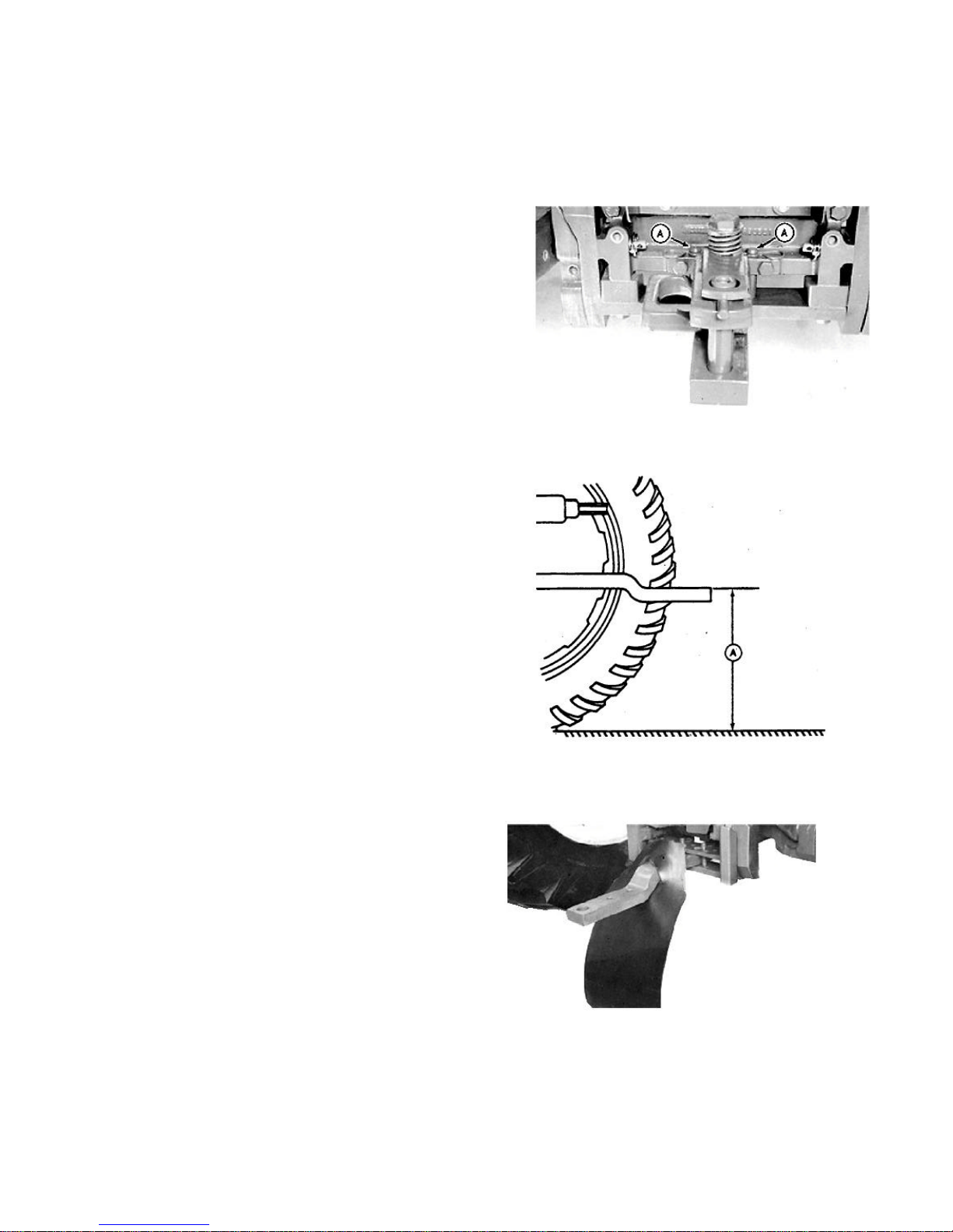
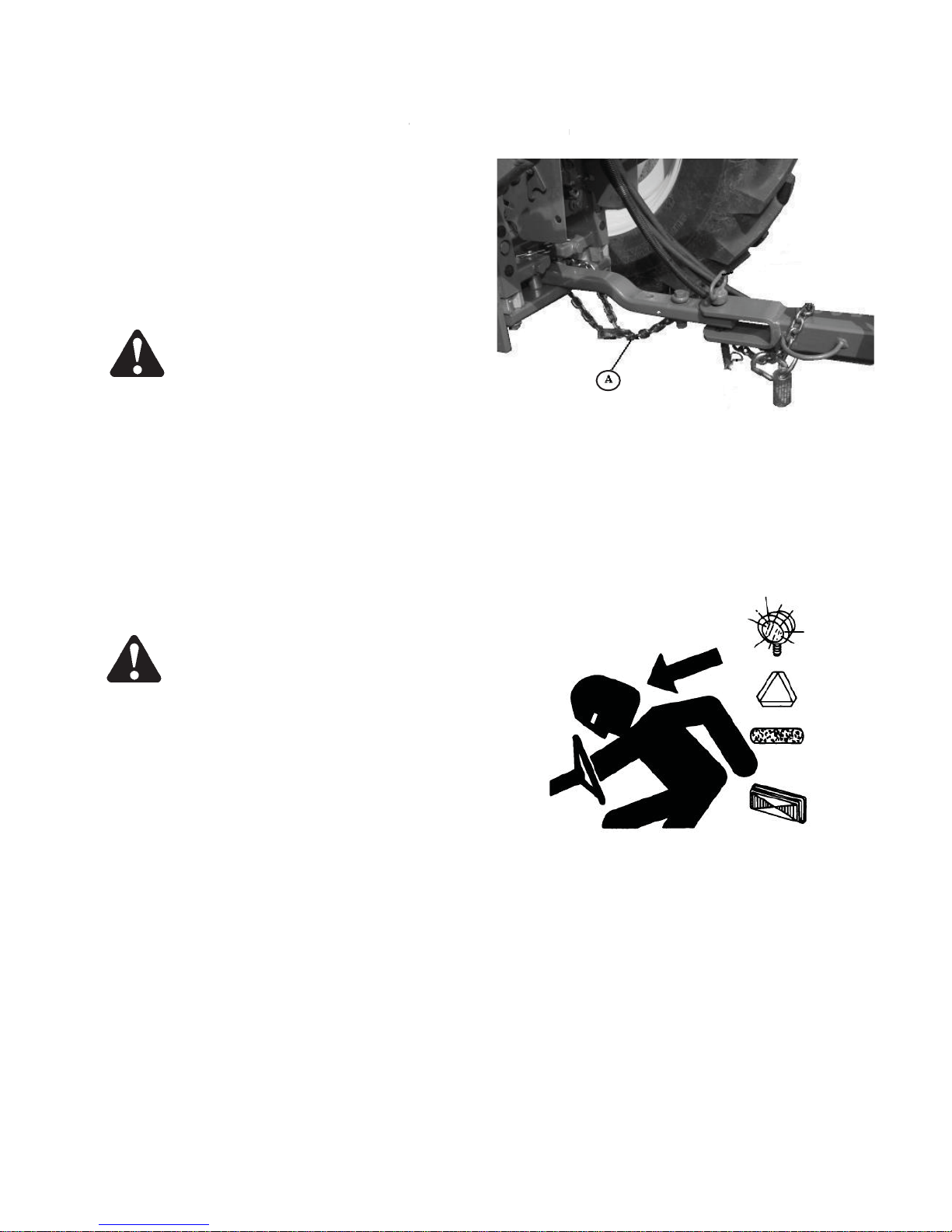
POSITIONING TRACTOR DRAWBAR
1. Remove locking pins (A) and move drawbar to center
position.
2. Install locking pins (A).
3. Extend drawbar away from tractor as far as possible
for better maneuverability when attaching, detaching,
and operating in the field.
4. Remove clevis assembly, if equipped.
5. If drawbar is offset, turn drawbar so offset is down, as
illustrated.
The rake can be attached to any tractor having a
drawbar that conforms to ASAE-SAE standards of 330
to 559 mm (13 to 22 in.) (A) from the ground.
USING DRAWBAR SHIELD
If a tractor drawbar catches and disturbs the windrow
under the tractor, a drawbar shield can be used.
See Making Drawbar Shield in this section.
14
PREPARING THE TRACTOR
D
PREPARING THE TRACTOR
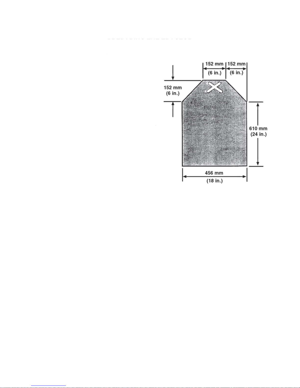
MAKING DRAWBAR SHIELD
MAKING DRAWBAR SHIEL
Use 2 or 4 ply belting.
THREE-POINT HITCH POSITION
IMPORTANT: To prevent damage to rake hitch
when making turns, make sure
draft links clear rake tongue.
Position tractor draft links to avoid interference with
rake tongue when making turns.
CHECKING BALLAST, WHEEL SPACING,
AND TIRE INFLATION
Provide sufficient weight to stabilize tractor when
operating on hilly land or other adverse conditions. (See
your tractor operator’s manual.)
To insure proper stability, adjust ballast, wheel spacing
and tire inflation according to tractor operator’s manual.
15
PREPARING THE RAKE
CHECKING TIRE INFLATION PRESSURE
To maintain machine efficiency, use only the tires
specified.
TIRE SIZE TIRE PRESSURE
5.00x15" directional 275 kPa (40 psi) (2.7 Bar)
CHECKING WHEEL NUT TORQUE
Whenever a wheel has been removed and installed,
check torque after one hour of operation and at 50 hour
intervals. Wheel nut should be tightened to 115 N•m (85
lb-ft).
16
ATTACHING AND DETACHING
ATTACHING AND DETACHING
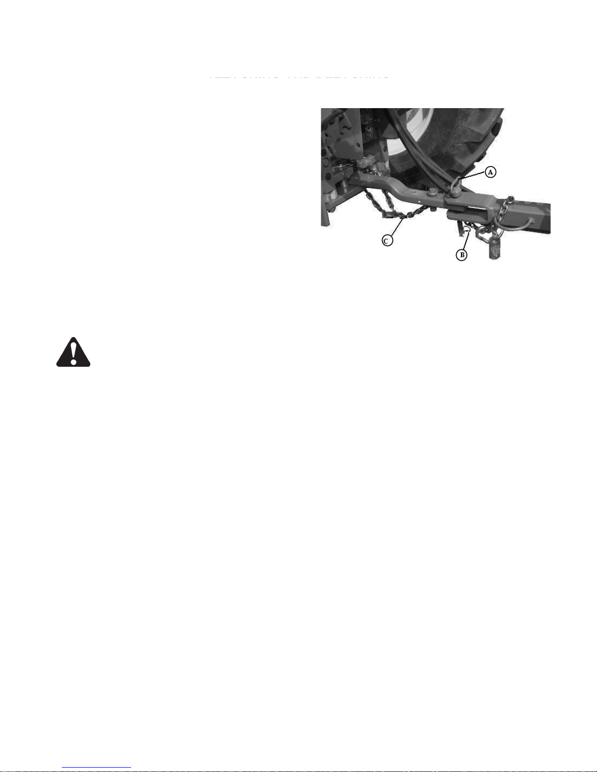
ATTACHING RAKE TO TRACTOR DRAWBAR
1. Position tractor drawbar. (See Positioning Tractor
Drawbar in Preparing the Tractor section.)
2. Remove hitch pin.
3. Back up tractor to rake. Align hitch pin holes in tractor
drawbar and rake tongue.
4. Engage tractor parking brake and/or place
transmission in “Park.”
5. Shut off tractor engine and remove key
B—
6. Install hitch pin (A). Fasten with quick-lock pin.
. A—Hitch Pin
C—Chain
CAUTION: A safety chain will help control
drawn equipment should it accidentally
separate from the drawbar. A runaway machine
could cause severe injury or death to someone.
Provide only enough slack in chain to permit
turning. Do not use safety chain for towing.
7. Connect chain (C) to rake tongue. Route chain
through loop on drawbar and connect to tractor drawbar
support. Do not fasten to drawbar. Remove all slack
except what is needed for turns.
Quick-lock Pin
17
ATTACHING AND DETACHING
G
ATTACHING AND DETACHING
TTACHING AND DETACHIN
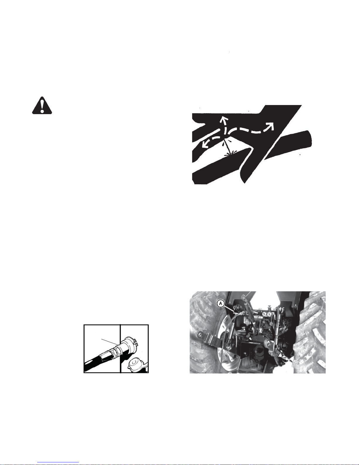
ATTACHING TO TRACTOR HYDRAULIC
SYSTEM
CAUTION: Escaping fluid under pressure
can penetrate the skin causing serious
injury. Avoid the hazard by relieving
pressure before disconnecting hydraulic
or other lines. Tighten all connections
before applying pressure.
Search for leaks with a piece of cardboard.
Protect hands and body from high
pressure fluids.
If an accident occurs, see a doctor
immediately. Any fluid injected into the
skin must be surgically removed within a
few hours or gangrene may result. Doctors
unfamiliar with this type of injury should
reference a knowledgeable medical
source. Such information is available from
Deere & Company Medical Department in
Moline, Illinois, U.S.A.
1. Push tractor SCV levers in the float position.
2. Connect hydraulic hose (A) to tractor receptacles. Remove any storage from the cylinder
3. Put tractor SCV levers in the neutral position
A
18
ATTACHING AND DETACHING
DETACHING RAKE FROM TRACTOR
CAUTION: To prevent personal injury caused by
unexpected movement:
• Park machines on a level surface.
• Engage tractor parking brake and/or place
transmission in “Park.”
• Shut off tractor engine and remove key.
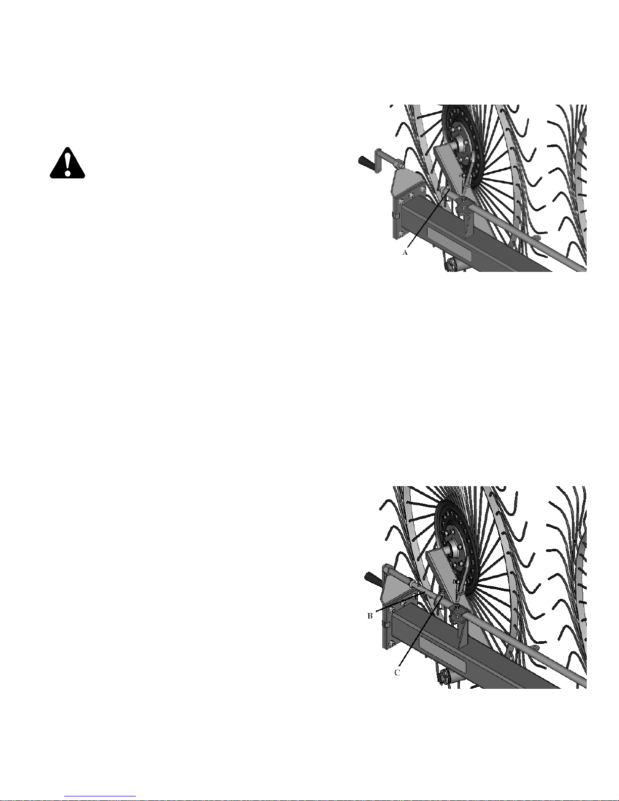
1. Fold and lock rake frame arms in transport position.
(See Preparing Rake for Transport in the Transporting
section.)
2. Lower rake wheels, or raise rake wheels fully and lock
in transport position.
If rake wheels are raised:
• Remove spring-clip pin from operating position (A).
• Pull short pipe (B) out and align pipe holes. Install
spring-clip pin in transport position (C).
3. Park rake on a level surface, or block ground wheels
so machine cannot roll after detaching from tractor.
4. Engage tractor parking brake and/or place transmission
in ’Park.”
5. Shut off tractor engine and remove key.
6. Push tractor SCV levers to the float position.
A—Pin in Operating Position
B—Pipe
C—Pin in Transport Position
19
ATTACHING AND DETACHING
A
TTACHING AND DETACHING
CAUTION: Escaping fluid under pressure
can penetrate the skin causing serious
injury. Avoid the hazard by relieving
pressure before disconnecting hydraulic
or other lines. Tighten all connections
before applying pressure.
Search for leaks with a piece of
cardboard.
Protect hands and body from high
pressure fluids.
If an accident occurs, see a doctor
immediately. Any fluid injected into the
skin must be surgically removed within a
few hours or gangrene may result.
Doctors unfamiliar with this type of injury
should reference a knowledgeable
medical source, such information is
available from Deere & Company
Medical Department in Moline, Illinois,
U.S.A.
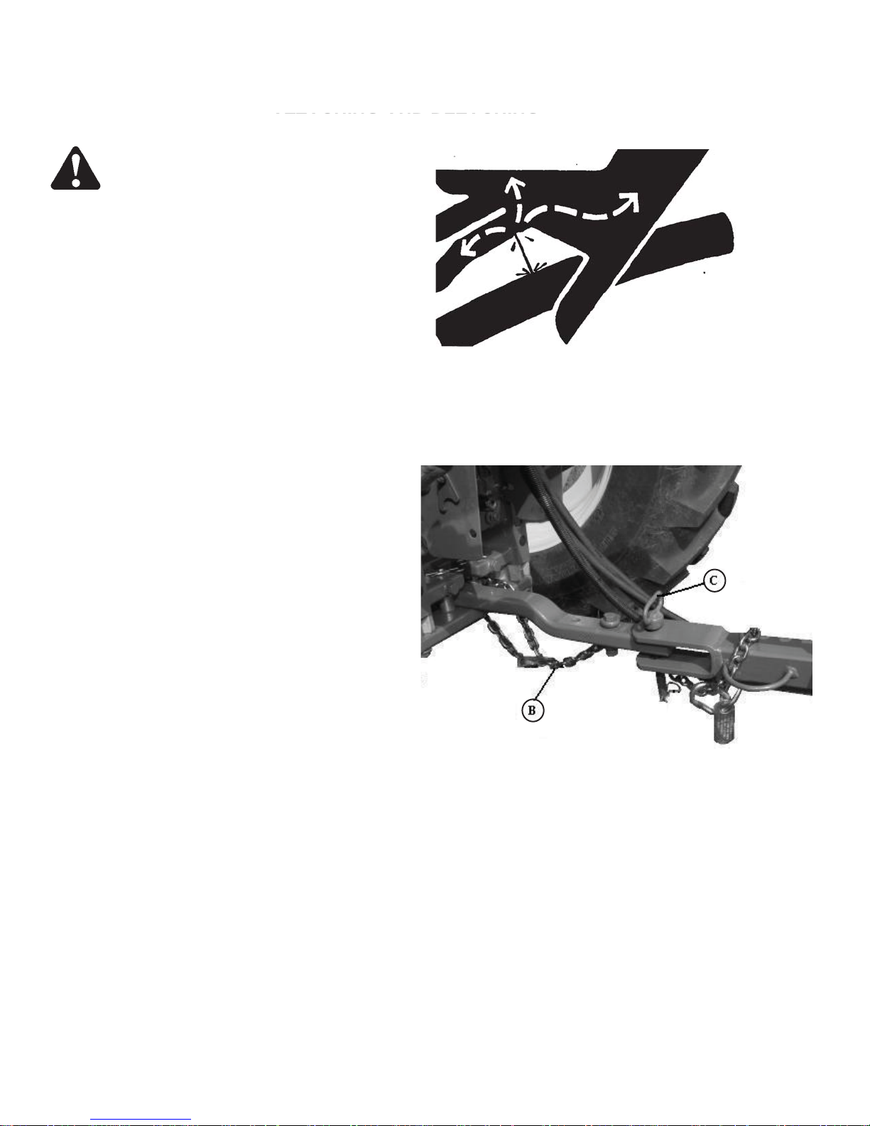
8. Disconnect hydraulic hoses (A) from tractor
receptacles.
9. Unhook safety chain (B).
10. Remove hitch pin (C).
11. Put tractor SCV levers in the neutral position.
A—Hydraulic Hose
B—Safety Chain
C—Hitch Pin
20
TRANSPORTING
G
TRANSPORTIN
PREPARING RAKE FOR TRANSPORT
1. Park rake on level surface.
2. Engage tractor parking brake and/or place
transmission in “Park.”
3. Shut off tractor engine and remove key.
CAUTION: A safety chain will help control
drawn equipment should it accidentally
separate from the drawbar. A runaway
machine could cause severe injury or
death to someone.
Provide only enough slack in chain to
permit turning. Do not use safety chain
for towing.
4. Make sure safety chain (A) is attached. Provide only
enough slack in chain to permit turning.
CAUTION: Prevent collisions between
other road users, slow moving tractors
with attachments or towed equipment,
and self-propelled machines on public
roads.
Frequently check for traffic from the rear,
especially in turns, and use hand signals
or turn signal lights.
Use headlights, flashing warning lights,
and turn signals day and night. Follow
local regulations for equipment lighting
and marking.
Keep lighting and marking visible and in
good working order. Replace or repair
lighting and marking that has been
damaged or lost.
5. Be sure SMV emblem and reflectors are clean and
visible.
21

TRANSPORTING
6. Clean out any crop and chaff trapped between rake
tines and frame.
7. Raise raking wheels to their maximum height using
hydraulic cylinders.
8. Lock raking wheels for transport:
• Remove clip pin from operating position (A).
• Pull short pipe (B) out and align pipe holes.
• Install clip pin in transport position (C).
B—Pipe
C—Pin in Transport Position
A—Pin in Operating Position
TRANSPORTING
Close the rake to the transport position following these operationssss:
1. Pull the lever (1) to unhook the drawbar (2) from the regulating plate (3).
(use the cord with handle (4) to pull the lever from the tractor).
2. Rotate the drawbar towards the main rake frame to align the head of
the pivot (5) to the last hole of the regulating plate (3).
3. Release the lever to hook the drawbar to the regulating plate (3).
22
TRANSPORTING
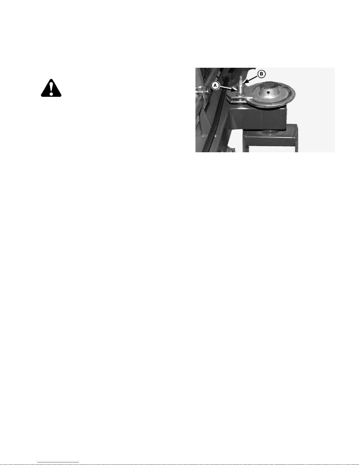
IMPORTANT: To avoid machine damage, do not
overtighten spring. Overtightening will
prevent the rake from opening and
closing when needed.
10. Spring (A) on wheel brake should be compressed 45
mm (1-25/32 in.) to keep wheel from wobbling. If
needed, turn nut (B) one revolution to increase spring
compression. Repeat as necessary.
A—Spring
B—Nut
23

OPERATING THE RAKE
PRESTARTING CHECKS
CAUTION: To prevent personal injury caused by
unexpected movement:
• Park machine on a level surface.
• Engage tractor parking brake and/or place
transmission in “Park.”
• Shut off tractor engine and remove key.
Inspect and service machine before starting work each
day.
• Check for any loose tines, bolts or missing hardware.
• Check tire inflation pressure. Correct tire pressure is
275 kPa (40 psi) (2.7 Bar).
• Check wheel nut torque. Wheel nuts should be tightened
to 115 N•m (85 lb-ft).
PREPARING RAKE FOR FIELD OPERATION
CAUTION: To prevent personal injury caused by
unexpected movement:
• Park machine on a level surface.
• Engage tractor parking brake and/or place
transmission in “Park.”
• Shut off tractor engine and remove key.
1. Park machines on level surface.
2. Move tractor SCV levers to the neutral position.
24

OPERATING THE RAKE
CAUTION: Avoid serious crushing injury when
opening or closing the rake. Make sure
bystanders are clear of rake and area is free
from obstructions before opening or closing
rake.
IMPORTANT: Do not replace hydraulic cylinder for rake
wheel lift regulation with a different size
hydraulic cylinder, or damage to opening
system may occur. Cylinder diameter should
be 60mm (2 in.) with a 203 mm (8-in.) stroke.
Cylinder length when completely closed
should be 463 mm (18 in.)
4. Move rake wheel lift rod to operating position:
• Raise rake wheels to maximum height.
• Remove spring-clip pin (A) from transport position.
• Push short pipe section into end of rear pipe. Align
the hole nearest washer (B) with the hole in
rear pipe.
• Install spring clip in operating position (C).
• Open rake to operating width.
• Lower rake wheels.
5. Check raking wheel ground pressure. Adjust as
required.
A—Spring-Clip Pin
B—Washer
C—Operating Position
25

OPERATING THE RAKE
OPERATING THE RAKE
CAUTION: To avoid bodily injury:
• Keep bystanders away from machine
while it is operating as foreign objects may
be thrown by machine.
• Allow only the operator on tractor
platform when operating the tractor and
rake.
• Slow down when turning or traveling
over rough terrain.
• Engage tractor parking brake and/or
place transmission in “Park,” shut off
tractor engine and remove key before
servicing or making adjustments to rake.
Regulate ground speed according to crop condition,
terrain, and tractor horsepower. In general, raking
speeds at 8—11 km/h (5—7 mph) will produce good
results. A slower ground speed may be necessary for
hills or rough terrain.
For sickle mowed crop, rake in the same direction as
mower travel.
For rotary mowed crop, rake in opposite direction as
mower travel.
26

SETTING WORKING WIDTH
A
OPERATING THE RAKE
NOTE: Windrow widths (A) are approximate.
The working width will vary due to the type
and quantity of crop being raked, volume,
and raking speed
To obtain the desired working width, or change
from the former one, just pull the lever (1) to
unhook the drawbar (2) from the regulating plate
(3). (Use the cord with handle (4) to pull the
lever from the tractor).Then rotate the drawbar
to align the head of the pivot (5) to one of the
holes of the regulating plate (3). Release the lever
to hook the drawbar to the regulating plates (3).
Working Width
9 Wheel Rake
(A)
0 to 6.05m
(0in. to 20 ft 2 in.)
Working Width
6 Wheel Rake
(A)
0 to 4.10m
(0in. to 13 ft 8 in.)
27

OPERATING THE RAKE
ADJUSTING RAKING WHEEL HEIGHT
Each raking wheel is independently spring loaded to allow
each wheel to follow the ground contour. The raking
wheels should lightly touch the ground and turn during
operation. The correct ground pressure on raking wheels
may vary depending on field conditions and the type and
quantity of crop being raked.
To adjust raking wheel height:
1. Lower raking wheels.
2. Make sure spring-lock pin (A) is in operation position.
3. Turn crank (B) clockwise to decrease ground pressure;
turn crank (B) counterclockwise to increase ground
pressure.
DIRECTION OF TRAVEL
The rake is provided with a directional ground wheel (1) that can
be set following this operation:
1. Remove the pin (2)
2. Rotate the directional ground wheel (1) to align the correct hole of
the plate (3) to one of the two holes of the two plates (4) and fix
the directional ground wheel with pin (2).
A—Spring-Lock Pin
B—Crank
28

LUBRICATION AND MAINTENANCE
PERFORM LUBRICATION AND MAINTENANCE
CAUTION: Do not clean, lubricate or
adjust machine while it is running.
• Park machine on level surface.
• Engage tractor parking brake and/or
place transmission in “Park.”
• Shut off tractor engine and remove key .
IMPORTANT: The recommended intervals are
based on normal conditions.
Severe or unusual conditions may
require shorter intervals.
Perform each lubrication and maintenance illustrated
in this section at the beginning of the season and at
the end of the season.
Clean lubrication fittings before lubricating. Replace
lost or broken fittings immediately. If a new fitting fails
to take grease, remove and check for failure of
adjoining parts.
OBSERVE LUBRICATION SYMBOLS
Follow hourly (C) intervals on grease symbols (A) and
oil symbols (B).
GREASE SYMBOL (A) (D) Lubricate with High Temp
EP grease or equivalent SAE multipurpose grease
(unless otherwise specified) at hourly intervals
indicated on the symbols.
OIL SYMBOL (B) Lubricate with SAE 30 or heavier oil
at hourly intervals indicated on the symbols.
Lubrication Symbols
A—Grease Symbols
B—Oil Symbols
C—Hourly Intervals
D— Grease Symbols
29

LUBRICATION AND MAINTENANCE
ALTERNATIVE AND SYNTHETIC LUBRICANTS
Conditions in certain geographical areas may require
lubricant recommendations different from those
printed in this manual.
Some coolants and lubricants may not be available in
your location.
Consult your Frontier dealer to obtain information and
recommendations.
Synthetic lubricants may be used if they meet the
performance requirements as shown in this manual.
The temperature limits and service intervals shown in
this manual apply to both conventional and synthetic
oils.
Refined base stock products may be used if
finished lubricant meets the performance
requirements.
the
GREASE
Use grease based on NLGI consistency numbers and
the expected air temperature range during the service
interval.
The following greases are preferred:
• John Deere HD POLYUREA GREASE
The following greases are also recommended:
• John Deere HD MOLY GREASE
• John Deere HD LITHIUM COMPLEX GREASE
• John Deere HD WATER RESISTANT GREASE
• John Deere GREASE-GARD
Other greases may be used if they meet the following:
• NLGI Performance Classification GC-LB
IMPORTANT: Some types of grease thickener are
not compatible with others.
30

LUBRICANT STORAGE
LUBRICATION AND MAINTENANCE
Your equipment can operate at top efficiency only
when clean lubricants are used.
Use clean containers to handle all lubricants.
Whenever possible, store lubricants and containers in
an area protected from dust, moisture, and other
contamination. Store containers on their side to avoid
water and dirt accumulation.
EVERY 10 HOURS
Check all attaching hardware every 10 hours, especially
during the first 50 hours of operation. Make sure bolts are
correctly torqued. (See Specifications section for bolt
torque charts.)
− Rake Wheels
Make certain that all containers are properly marked to
identify their contents.
Properly dispose of all old containers and any residual
lubricant they may contain.
31

LUBRICATION AND MAINTENANCE
EVERY 50 HOURS
• Right-Hand and Left-Hand Pivoting Wheels
• Lift Pipe Supports
• Check Wheel Nut Torque
Torque to 85 lb-ft (115 N•m).
32

• Grease Drawbar Support
LUBRICATION AND MAINTENANCE
EVERY 100 HOURS
· Grease Drawbar Support
33

LUBRICATION AND MAINTENANCE
ANNUALLY
Repack Wheel Bearings:
1. Raise one side of machine and install support stands.
2. Remove wheel.
3. Remove hub cap, cotter pin, and wheel nut
4. Remove washer, bearing, and wheel hub.
5. Remove rear seal and bearing.
6. Clean all parts in solvent and blow dry with
compressed air. Replace any worn or damaged parts.
7. Pack bearings with John Deere EP Moly or an
equivalent SAE multipurpose type grease, or wheel
bearing grease. Coat rear seal with same grease.
8. Install rear bearing and seal.
9. Install wheel hub, front bearing, washer and nut.
Tighten nut until a slight drag is felt when hub is
turned. Back nut off just enough to install cotter pin in
hole in spindle.
10. Install hub cap and wheel. Tighten wheel hardware to
115 Nm (85 lb-ft).
11. Repeat procedure on other wheel.
12. Check wheel hardware torque after 10 hours of
operation.
34

LUBRICATION AND MAINTENANCE
AS REQUIRED
Periodically inspect rake and make necessary repairs.
• Check frame for fatigue or cracking. Replace or repair
worn or damaged parts.
• Check decals; replace if missing or damaged.
• Check bolts and fasteners; tighten or replace as
necessary.
• Check tire pressure. Inflate to 275 kPa (40 psi) (2.7 Bar).
• Check tires and rims for damage.
• Check condition of raking wheels for loose hardware,
loose bearings, and broken or bent tines.
• Check hydraulic cylinders and hoses for leaks or
damage.
35

TROUBLESHOOTING
HYDRAULIC PROBLEMS
Symptom Problem Solution
Hydraulic system inoperative. Remote outlet valve not activated. Open remote hydraulic outlet valve.
Hose from implement not properly Connect hose.
connected to tractor.
Hydraulic oil level too low in tractor. Check tractor operator’s manual for
proper oil level.
36

TROUBLESHOOTING
RAKING PROBLEMS
Symptom Problem Solution
Field not cleaned well. Rake wheels too high. Adjust rake wheels lower to ground.
Hay is bunching. Tips of tines collecting dirt. Remove paint and dirt from tips of
tines.
Incorrect ground speed. Increase or decrease ground speed.
Steel burrs on tines or hoops. Remove burrs.
Rake wheel hoops breaking. Excessive ground speed. Reduce ground speed.
Excessive ground pressure. Reduce ground pressure.
Tines breaking. Excessive ground speed. Reduce ground speed
Excessive ground pressure. Reduce ground pressure.
Rake wheel does not turn. Inadequate lubrication. Lubricate wheel. (See Lubrication
and Maintenance section.)
Failed bearing. Replace bearing.
Poor windrow preparation. Rake wheels too high. Lower rake wheels.
Broken or missing tines. Replace tines.
Excessive ground speed. Reduce ground speed.
Slow ground speed. Increase ground speed.
Excessive ground pressure. Reduce ground pressure.
Rake wheels do not turn Rake wheels too high. Lower rake wheels.
Broken or missing tines. Replace tines. (See Replacing
Wheel Tines in Service section.)
37

SERVICING TIRES SAFELY
CAUTION: Explosive separation of a tire
and rim parts can cause serious injury or
death.
Do not attempt to mount a tire unless you
have the proper equipment and
experience to perform the job.
Always maintain the correct tire
pressure. Do not inflate the tires above
the recommended pressure. Never weld
or heat a wheel and tire assembly. The
heat can cause an increase in air
pressure resulting in a tire explosion.
Welding can structurally weaken or
deform the wheel.
When inflating tires, use a clip-on chuck
and extension hose long enough to allow
you to stand to one side and NOT in front
of or over the tire assembly. Use a safety
cage if available.
SERVICE
Check wheels for low pressure, cuts,
bubbles, damaged rims, or missing lug
bolts and nuts.
SERVICING RAKE SAFELY
CAUTION: Avoid serious crushing
injury when closing or opening rake.
Make sure bystanders are clear of rake
before closing oropening.
38

SERVICE
REPLACING WHEEL TINES
To replace a tine:
1. Remove two round-head bolts (A), nuts, clip and
tine.
2. Install new tine. Fasten with clip, round-head bolts
(A) and nuts.
l
39

STORAGE
END OF SEASON
1. Clean rake thoroughly. Trash and dirt will draw
moisture and cause rust.
2. Put rake in a dry place.
3. Thoroughly lubricate machine. (See Lubrication and
Maintenance section.)
4. Apply a thin layer of grease on exposed cylinder
rods to prevent rusting.
5. Check hydraulic hoses for deterioration and replace
if necessary.
6. Tighten any loose bolts, nuts, and hydraulic fittings.
7. Repair or replace worn or broken parts.
8. Paint all parts where necessary.
9. Replace damaged or missing decals.
10. List replacement parts needed and order them
early.
BEGINNING OF SEASON
1. Review operator’s manual and check adjustments.
2. Lubricate complete machine. (See Lubrication and
Maintenance section.)
3. Check air pressure in tires. Correct tire pressure is
275 kPa (40 psi) (2.7 Bar).
4. Check all hardware for tightness.
5. If any major moving parts have been replaced,
make sure they run properly.
40

HIGH-CAPACITY WHEEL RAKE CHECKLISTS
DEALERS RECORD
Owner’s Name: Date Sold:
Address: Model Number:
City: Serial Number:
State: Zip:
PREDELIVERY
After the rake has been completely set up, make
sure it is in good running condition before delivering
to the customer. The following checklist is a
reminder of important points to inspect. Check off
each item after it is found satisfactory or after the
correct adjustment is made.
- Rake has been assembled correctly.
- Check hydraulic hose and connection for oil leaks
or damage.
- Check machine for loose hardware.
- Machine lubricated. (See Lubrication and
Maintenance.)
- Check condition of rake wheels tines.
- Check that all rake wheels pivot freely.
- Check all phases of operation.
- Check that safety chain is installed.
- Tire pressures checked.
- Check wheel bolt torque.
- Decals intact and legible.
- Touch up paint, if necessary.
(Date set up)
(Signature)
41

DELIVERY
The following checklist is a reminder of very
important information which should be conveyed to
the customer at the time the machine is delivered.
Check off each item as it is fully explained to the
customer.
- Warranty statement.
- Safe and correct operation and service.
- Advise customer that the life expectancy of the
rake, like any other machine, is dependent upon
regular lubrication and maintenance as described in
the operator’s manuals.
- Daily and periodic inspections.
- Servicing machine regularly and correctly.
- Advise to use safety chain.
- Make customer aware of optional equipment
offered for this machine.
- Transporting machine correctly
- Storing machine correctly.
- Frontier parts and service.
- Give operator’s manual to customer and explain all
operating adjustments and lubrication and
maintenance intervals. Encourage customer to
read manual.
- Have customer record machine serial number in
the Specifications section.
- Remove and file this page.
(Date Delivered)
(Signature)
42

ASSEMBLY
INSTALL RAKE WHEELS FRAMES
ON LEVEL GROUND, PLACE 2 STANDS (1) APPROXIMATELY 5 TO 6 FEET (1,5 TO 1,8 mt.) APPART AND
ADJUSTED TO A HEIGHT OF ABOUT 29 INCHES (74 cm). PLACE THE FRONT FRAME (2) ON TOP OF
THE STANDS. POSITION ANOTHER STAND (3) TO SUPPORT THE REAR FRAME (4). NOW FASTEN THE
TWO MAIN FRAME MEMBERS (2) AND (4) TOGETHER WITH 12X35 mm HEX BOLTS AND LOCK NUTS.
NOTE, TIGHTEN THESE BOLTS EVENLY TO INSURE THET THE FRAMES ARE CONNECTED STRAIGHT.
ASSEMBLE THE ARM FOR DRAWBAR (7) ONTO THE MAIN FRAME (2) IN THE POSITION SHOWN IN THE
FIGURE. USE M12X30 HEX BOLTS (10) AND THE MOUNTING BRACKET FOR THE FRONT GROUND
WHEEL (9) TO FASTEN THE ARM TO THE FRAME.
NOW PLACE A ASSEMBLY STAND (8) IN A POSITION TO SUSTAIN THE SUPPORT OF DRAWBAR (12).
ASSEMBLE THE SUPPORT FOR DRAWBAR (12) ONTO THE ARM FOR DRAWBAR (7) WITH M12X30 HEX
BOLTS (13) AND MOUNTING PLATE (15).
43

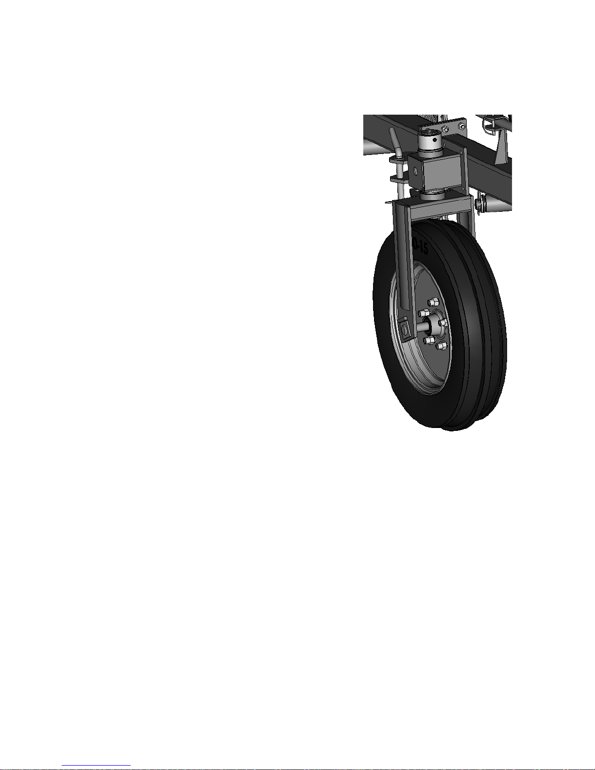
INSTALL THE GROUND WHEELS
ASSEMBLE THE WHEEL WITH HUB (1) ONTO THE WHEEL FORK (2) USING THE WHEEL FORK M24X260
PIVOT (3), WHICH HAS PREVIOUSLY BEEN GREASED, AND NYLON SELF LOCKING NUT (4) AND
THE TWO SPACERS (5) AND (6) WHICH MEASURE 64mm LONG AND 58mm LONG. THE ASSEMBLY OF
THESE TWO SPACERS IS CARRIED OUT BY POSITIONING THE WHEEL IN THE CENTER OF THE
WHEEL FORK.
GREASE THE UPPER PIVOT SHAFT AREA (2) AND INSERT IT INTO THE GROUND WHEEL MOUNTING
BRACKET(7). POSITION THE SUPPORT FORK GROUND WHEEL REAR (8) FOUR INCHES (10 cm) FROM
THE FLANGE OF THE FRAME. NOW FASTEN THE SUPPORT (8) TO THE REAR FRAME WITH FOUR
M12x140 HEX BOLTS (10), AND MOUNTING PLATE (9). MOUNT THE GROUND WHEEL REAR (12).
GREASE THE UPPER PIVOT SHAFT AREA AND INSERT IT INTO THE GROUND WHEEL MOUNTING
BRACKET (8).
THEN SLIDE THE RING FOR REAR WHEEL SUPPORT (13) ON THE UPPER PIVOT SHAFT OF THE
GROUND WHEEL ASSY AND SECURE WITH A M10X70 ROLL PIN (14). INSTALL THE OTHER FRONT
GROUND WHEEL (17).
PRE-ASSEMBLE BRAKE DISC (18) PLATES AND SPRING (19) THEN SLIDE THEM ON THE UPPER PIVOT
SHAFT OF THE GROUND WHEEL ASSY (17). SECURE THIS ASSEMBLY WITH A M10X70 ROLL PIN (20).
44

ASSEMBLY FRAMES
MOUNT THE FRAME EXTENSION (1) TO THE END OF THE REAR FRAME (2) WITH M12X35 CAP SCREW
AND M12 LOCK NUT. ATTACH THE PLATE FOR LIFT SCREW (9) ONTO THE EXTENSION FRAME (1)
WITH M12X35 CAP SCREW AND M12 LOCK NUT. MOUNT THE FRAME EXTENSION (4) TO THE END OF
THE FRONT FRAME (3) WITH M12X35 CAP SCREW AND M12 LOCK NUT. INSTALL THE LIFT PIPES (5),
(6), (7) AND (8) AS SHOWN IN THE PICTURE AND SECURE THEM WITH M8X50 HEX BOLT (10) AND LOCK
NUT M8 (11). PUT THE LIFT PIPES IN THEIR LOCATION ON THE WING FRAMES AND LOCK WITH THE
SPRING CLIP PIN (20). INSERT THE LONG FLAT HEADED PIN (19) INTO THE REAR LIFT TUBE (5) . THIS
PIN HAS TWO HOLES. ALIGN THE HOLE NEAREST THE HEAD WITH THE HOLE IN THE LIFT TUBE AND
SECURE WITH A SPRING CLIP PIN (20). INSTALL THE HANDLE (15) HAS SHOWN IN THE PICTURE WITH
THE M12x90 TCEI SCREW (16), M12 NUT, HANDLE AND CAP.
45

ASSEMBLY DRAWBAR
NOW ASSEMBLE THE REGULATING PLATE (3) TO THE SUPPORT FOR DRAWBAR (2) WITH M30X180
PIVOT (14), SUPPORT (15) AND LOCK NUT (21). INSTALL THE GREASE ZERK (22). ASSEMBLE THE
REGULATING PLATE (3) ONTO THE DRAWBAR (1) AND SECURE WITH THE M24X125 PIVOT (13) AND
NUT (16). ATTACH THE LEVER (9) TO THE MOUNTING EARS ON THE DRAWBAR (1) WITH HEX BOLT
M8X30 AND NUT. INSERT THE SPRING (12) INTO THE M25X205 PIVOT (11) AS SHOWN IN THE PICTURE
AND SECURE WITH A 25X50X2.5 WASHER (23) AND A SPLIT PIN 5X40 (24). SECURE THE LEVER (9) TO
THE M25X205 PIVOT (11) WITH A CLEVIS (10) AND ATTACH THE CORD (7) WITH HANDLE (8).
24
11
23
12
46

INSTALL HYDRAULIC CIRCUIT
MOUNT THE HYDRAULIC CYLINDER (7) ON THE FRAME AND FASTEN WITH PINS (10) AND SPRING
PIN (11). INSERT M10X150 ROD (8)THROUGH SPRING (9).SECURE THIS ASSEMBLY BETWEEN PINS
(10)BY TWO M10 NUTS (12)ON REAR SIDE. ATTACH THE CYLINDER TO THE LIFT TUBE USING THE
CYLINDER MOUNTING PIN (10). ATTACH SPRING (9)TO THE TABS ON THE MOUNTING PINS.TIGHTEN
THE SPRING NUTS (12)TILL THE SPRING TENSIO
REMOVE TWO PLUGS AND INSTALL BREATHER (5)ON THE ROD END PORT AND 3/8 PIPE TREAD TO
FLARE,90-DEGREE ELBOW FITTING (6).CONNECT THE HOSE (4)TO (6). INSTALL HOSE CLAMPS AND
FASTEN WITH M6X25 SOCKETHEAD SCREWS ALONG THE FRAME.
NS STRETCHED ABOUT 1/2 INCH (1.3 cm).
47

ASSEMBLY RAKE WHEELS
INSTALL THE NYLON BUSHINGS (4) INTO THE RAKE ARM MOUNTING TUBES ON THE FRAMES.
INSTALL THE RAKE WHEEL ARMS (7) THROUGH THE MOUNTING TUBES WITH NYLON BUSHING AND
SECURE WITH M32X53X5 FLAT WASHER (6) AND 5mm DIAMETER SPRING PIN (5). SLIDE THE CHAIN
(10) THROUGH THE END OF THE SPRING (8). ATTACH THE RAKE WHEEL SUSPENSION SPRING TO
THE TAB OF THE RAKE ARM (7) AND LIFTING PIPE TAB. SECURE THE CHAIN (10) TO THE ARM TAB BY
THE SHACKLE (9). NOW MOUNT ALL THE RAKE WHEELS (1) TO THE HUBS OF THE RAKE WHEEL
ARMS. (TINE MIG. CLIPS TO FRONT). USE THE M10X25 HEX BOLTS (2), 10X21X2 FLAT WASHERS (3)
AND HEX NUTS (10) . BOLT HEAD AND WASHER ON THE FRONT SIDE OF THE RAKE WHEEL. HEX NUT
ON THE BACK SIDE OF THE HUB.
48

INSTALL SMV EMBLEM
INSTALL SLOW MOVING VEHICLE (SMV) BRACKET (4). FASTEN WITH 12X102X125 U-BOLT (6) AND M12
NUTS (5). INSTALL SMV EMBLEM (2) WITH M6X16 SCREWS (1) AND M6 NUTS (3).
49

INSTALL TRANSPORT LIGHTS
5
6
4
7
8
3
10
9
2
11
rear view
12
FASTEN BRACKET (3) WITH M12X102X125 U-BOLT (9) AND TWO M12 NUTS (2). INSTALL RED TAIL
LIGHT (6) TO REAR OF BRACKET. FASTEN WITH TWO M8X16 CAP SCREWS (8). INSTALL YELLOW
LAMP (7) THROUGH BRACKET SLOT. TIGHTEN NUT. ATTACH WIRING HARNESS (1) TO WARNING
LAMP CONNECTOR AND TAIL LAMP SOCKET. POSITION THE WIRING HARNESS (1) ALONG FRAME
TUBE AND FASTEN WITH THE WIRE CLIP (11) AND TIE BANDS (10). ONNECT THE SIGNAL MODULE (12)
AND FASTEN WITH TIE BANDS (10).
50

FINAL INSPECTION AND LUBRICATION
FINAL INSPECTION AND LUBRICATION
CAUTION: Escaping fluid under
pressure can penetrate the skin causing
serious injury. Avoid the hazard by
relieving pressure before disconnecting
hydraulic or other lines. Tighten all
connections before applying pressure.
Search for leaks with a piece of
cardboard.
Protect hands and body from high
pressure fluids.
If an accident occurs, see a doctor
immediately.
Any fluid injected into the skin must be
surgically removed within a few hours
or gangrene may result. Doctors
unfamiliar with this type of injury
should reference a knowledgeable
medical source. Such information is
available from Deere & Company
Medical Department in Moline, Illinois,
U.S.A.
1. Attach rake to tractor (Refer to Attaching and
Detaching section in operator’s manual.)
2. Make sure rake has enough clearance to raise and
lower.
3. Raise and lower rake. Check for interferences.
4. Shut off tractor. Check hydraulic system for leaks.
Oil coming out of lift cylinder vent for the first
few cycles is normal.
5. Lubricate entire machine. (See Lubrication and
Maintenance section in operator’s manual.)
51

SPECIFICATIONS
HIGH-CAPACITY WHEEL RAKE
Tractor Requirement:
Horsepower (Minimum) .......................................................................................................................................... 22.4Kw (30hp)
Hydraulic Pressure Required ........................................................................................................... 6895 kPa (1000 psi) (69 bar)
Hydraulic Flow Required ................................................................................................................................ 23 L/min (6 gal/min)
Hydraulic Outlets ......................................... ………………………………………………………...……......One set of remote outlet
Raking Width:
6 Wheel Rake .................................................................................................................................... 4,10 m (13 ft 8 in.)maximum
9 Wheel Rake ................................................................................................................................... 6,05 m (20 ft 2 in.) maximum
Windrow Width:
6 Wheel Rake ........................................................................................................................................................................ Fixed
9 Wheel Rake ........................................................................................................................................................................ Fixed
Overall Transport Width:
6 Wheel Rake ..........................................................................................................................................….….. 2.55 m (8 ft 4 in.)
9 Wheel Rake .......................................................................................................................................….…..... 2.55 m (8 ft 4 in.)
Overall Length:
6 Wheel Rake .................................................................................................................................…................ 7.55m (24 ft 7 in.)
9 Wheel Rake ...................................................................................................................................….............. 9.23m (30 ft 3 in.)
Shipping Weight (Approximate):
6 Wheel Rake ...................................................................................................................................................... 450 kg ( 990 lb)
9 Wheel Rake .......................................................................................................................................................585 kg (1287 lb)
Fold/Unfold ...................................................................................................................................................... Hydraulic cylinder
Adjustments:
Raking Width ..................................................................................................................................................................... Manual
Wheel Ground Pressure .................................................................................................................................................... Manual
Raking Wheels:
Drive System .........................................................................................................................................…............. Ground Driven
Number of Ground Wheels:
6 Wheel Rake ............................................................................................................................................................................. 3
9 Wheel Rake .............................................................................................…....................................................................…..... 3
Tires ..............................................................................................................................................................5.00x15" directional
52

SPECIFICATIONS
RECORD PRODUCT IDENTIFICATION
NUMBER
When ordering parts, always furnish model and serial
number as given on serial number plate. It will assist
your Frontier dealer in giving you prompt and efficient
service.
The serial number is located on top of right-hand rear
frame.
Record serial number in space provided.
_______________________________________
TIGHTENING FLARE TYPE TUBE FITTINGS
1. Check flare and flare seat for defects that might
cause leakage.
2. Align tube with fitting before tightening.
3. Lubricate connection and hand tighten swivel nut
until snug.
4. To prevent twisting the tube(s), use two wrenches.
Place one wrench on the connector body and with
the second, tighten the swivel nut to the torque
shown in this chart.
Recommended
Tube Across (After Finger
Size OD Flats Torque Value
(in.) (in.) (Nm) (lb-ft) (Flats) (Turns)
3/16 7/16 8 6 1 1/6
1/4 9/16 12 9 1 1/6
5/16 5/8 16 12 1 1/6
3/8 11/16 24 18 1 1/6
1/2 7/8 46 34 1 1/6
5/8 1 62 46 1 1/6
3/4 1-1/4 102 75 3/4 1/8
7/8 1-3/8 122 90 3/4 1/8
a
The torque values shown are based on lubricated connections as
in reassembly.
Nut Size Turns To Tighten
a
Tightening)
53

SPECIFICATIONS
UNIFIED INCH BOLT AND CAP SCREW TORQUE VALUES
54

SPECIFICATIONS
METRIC BOLT AND CAP SCREW TORQUE VALUES
55

NOTES

Spare Parts
FRONTIER HIGH-CAPACITY 6-WHEEL RAKE
MANUFACTURED (2008)
FRONTIER HIGH-CAPACITY 9-WHEEL RAKE
MANUFACTURED (2008)
(SPECIFICATIONS AND DESIGN SUBJECT TO CHANGE WITHOUT NOTICE.)
56

SERIAL NUMBER LISTING INFORMATION
SERIAL NUMBER INFORMATION IS LISTED TO SHOW ON WHICH MACHINES EACH PART CAN BE USED; FOR
EXAMPLE:
- THE PART CAN BE USED ON ALL MACHINES.
000000- THE PART CAN BE USED ON ALL MACHINES BEGINNING WITH THE SERIAL NUMBER LISTED.
-000000 THE PART CAN BE USED ON ALL MACHINES UP TO AND INCLUDING THE SERIAL NUMBER
LISTED.
000000-000000 THE PART CAN BE USED ON ALL MACHINES BETWEEN AND INCLUDING THE SERIAL NUMBERS
LISTED.
WHEN XXXXXX’S ARE LISTED IN PLACE OF A SERIAL NUMBER, A SERIAL NUMBER CHANGE WAS
MADE BUT THE EXACT SERIAL NUMBER WAS NOT AVAILABLE WHEN THE CATALOG WAS PRODUCED.
THE RAKE SERIAL NUMBER IS LOCATED ON THE LEFT-HAND SIDE OF TONGUE.
DIRECTION ARROW
ARROWS ARE USED WITH ILLUSTRATIONS TO INDICATE THE FRONT OF THE UNIT. "RIGHT-HAND" AND "LEFT-HAND" SIDES ARE
DETERMINED BY FACING IN THE DIRECTION OF MACHINE FORWARD TRAVEL.
BOX-ENCLOSED ILLUSTRATIONS
A KEY NUMBER, SHOWN IN THE PARTS LIST, IS ASSIGNED TO A BOX ENCLOSING ALL PARTS SOLD AS A
SERVICE ASSEMBLY.
BOLT AND CAP SCREW STRENGTH IDENTIFICATION
BOLTS AND CAP SCREWS REQUIRED TO HAVE HIGH-STRENGTH QUALITIES EQUIVALENT TO SAE GRADE 8 ARE
IDENTIFIED THROUGHOUT THIS CATALOG BY THE DESCRIPTION HS SAE 8. ALL STANDARD BOLTS AND CAP
SCREWS ARE SAE GRADE 5 OR LOWER.
SI UNITS OF MEASURE
METRIC DIMENSIONS ARE GIVEN, WHERE APPLICABLE, THROUGHOUT THIS PARTS CATALOG.
HOSE DIMENSIONS LISTED ARE EITHER FITTING SIZE X LENGTH X FITTING SIZE OR I.D. X LENGTH.
CHANGE INDICATOR LINE
(MICROFICHE CATALOGS ONLY)
CHANGES AFFECTING THE ORDERING OF PARTS ARE IDENTIFIED BY VERTICAL LINES MARKED IN THE LEFT-HAND
MARGIN OF REVISED PARTS LISTING IMAGES. A LINE IS ALSO AT THE LEFT-HAND EDGE OF THE SAME
PART NUMBER IN THE NUMERICAL INDEX TO SHOW THE LOCATION OF REVISED INFORMATION.
57

MAIN FRAME
58

MAIN FRAME
W
R
4
1
KEY PART NO. PART NAME QTY SERIAL NO.
1 5TNP50AV420 FRAME 2 RAKE WHEEL l=1590 1 X
2 5TNP50AV421 FRAME 3 RAKE WHEEL l=2270 1 X X
3 5TNP50AV422 FRAME 3 RAKE WHEEL l=2470 1 X X
4 TNP50AV070 EXTENTION l=800 R.H. 1 X
5 5TNP50GZ005 LIFT PIPE SHORT l=1530 ZINCED T/V 1 X
6 5TNP50GZ014 LIFT PIPE LONG l=2400 ZINCED T/V 1 X X
7 5TNP50GZ009 PIPE (RH LIFT EXT) 1 X X
8 TNP50GZ001 LIFT PIPE EXTEN. l=850 ZN 1 X
9 5TNP50HV012 BRACKET LIFT WHEEL ADJ. ZN 1 X
5TNP50HZ008 BRACKET LIFT WHEEL ADJ. ZN 1 X
10 TNV10AZ011 SCREW TE M8x50 UNI 5737 ZINCED 2 4
11 TNV20BZ001 SELF LOCKING NUT M8 UNI 7474 ZINC 2 4
12 5TNP50GZ018 JOINT LIFT TUBE l=200 1 X X
13 5TNV10AZ101 HEX.CAP SCREW TE M12x35 UNI5739 ZN 12 24
14 TNV20CZ003 NUT METABLOCK M12 DIN 980 ZINCED 12 24
15 TNV80A0001 KNOB 1033/FP D=12 W/COVER 1 X X
16 TNV10BZ003 SCREW TCEI M12x90 UNI 5931 ZINCED 1 X X
17 TNP50QZ014 THREADED HANDLE ZN 1 X X
18 TNV20AZ005 HEXAGONAL NUT 6S M12 UNI 5589 ZINC 1 X X
19 TNS20AZ002 PIVOT SAFETY FOR PARKING 1 X X
20 TNV45BZ001 PIN/LOCK d=8 l=60 7 10
21 5TNP50BV098 ARM ATTACHMENT FRAME T 1 2
22 5TNV10AZ100 SCREW TE M12x30 UNI 5739 ZINCED 20 X X
23 TNV20CZ003 NUT METABLOCK M12 DIN 980 ZINCED 20 X X
24 5TNP50DV005 WHEEL SUPPORT SIDE 1 X X
25 5TNP50HV016 BRACKET SUPPORT REAR WHEEL 1 2
26 5TNP50LV001 ARM CONNECTING BAR 1 X
27 5TNV70AZ001 U-BOLT M14x115x144 4
28 TNV20CZ004 NUT METABLOCK M14 DIN 980 8
0
6
W
R
4
1
0
9
REMARKS
59

DRAWBAR ASSEMBLY
60

DRAWBAR ASSEMBLY
W
R
4
1
KEY PART NO. PART NAME QTY SERIAL NO.
1 5TNP50FV005 DRAWBAR l=2300 1 X X
2 5TNP50BV097 ARM DRAWBAR ATTACHMENT 1 X X
3 5TNP50ZV125 PLATE ADJUSTMENT 1 X X
4 5TNP50HV016 BRACKET SUPPORT REAR WHEEL 1 2
5 5TNV10AZ100 SCREW TE M12x30 UNI 5739 ZINCED 10 X X
6 TNV20CZ003 NUT METABLOCK M12 DIN 980 ZINCED 1 X X
7 5TNC30DZ007 WIRE ROPE PLASTIFIED 1 X X
8 5TNV80A0002 HANDLE 1 X X
9 5TNC30BZ009 ROD LEVER ZINCED 1 X X
10 TNV50AZ001 U SHACKLE 1/4" ZN 1 X X
11 5TNC70BZ019 PIN FOR SECTOR ZINCED 1 X X
12 5TNC40AZ002 SPRING ZINCED SECTOR DRAWBAR 1 X X
13 5TNP50ZZ037 PIN ATTACHMENT DRAWBAR 1 X X
14 5TNC70BZ060 PIVOT D=32 M 30 L=180 zn 1 X X
15 5TNP70PV574 FRONT AMBER REFLECT SUPPORT 1 X X
16 TNV20BZ021 SELF LOCKING NUT NY.M24x2 UNI7474 Z 3 X X
17 TNV30AZ014 WASHER 25x50x2.5 ZINCED 2 X X
18 TNV40CZ002 SPLIT PIN D=5x40 UNI 1336 ZINCED 1 X X
19 5TNV85B0001 CLAMP FOR 1 HOSE 6 X X
20 TNV10BZ001 SCREW TCEI M6x25 UNI 5931 ZINCED 12 X X
21 5TNV20BZ015 SELF LOCKING NUT NYLON M30 UNI7473 1 X X
22 TNV99AZ001 GREASER 10 MB 1 X X
23 TNC45BZ001 SAFETY CHAIN 1 X X
0
6
W
R
4
1
0
9
REMARKS
61

FRONT CRAZY WHEEL AND DIRECTIONAL WHEEL ASSEMBLY
62

FRONT CRAZY WHEEL AND DIRECTIONAL WHEEL ASSEMBLY
W
W
R
R
4
4
1
1
0
KEY PART NO. PART NAME QTY SERIAL NO.
1 5TNC40AZ018 SPRING FOR BRAKE d=5 mm ZN 2 x x
2 TNV30BZ004 WASHER 12x36x3 UNI 6593 ZINCED 2 x x
3 TNV20CZ003 NUT METABLOCK M12 DIN 980 ZINCED 2 14
4 5TNC80AZ002 PLATE BRAKES W/PIVOT ZN. 2 x x
5 TNC80AZ001 PLATE FOR BRAKES ZN. 2 x x
6 TNS90E0001 BRAKE ASSEMBLY 2 x x
7 TNC80CZ001 DISC FOR BRAKES ZN. 2 x x
8 TNV40B0010 ELASTIC PIN D. 10x70 UNI6873 3 x x
9 TNS20B0001 BRASS BUSHING FOR WHEEL 6 x x
10 TNV99AZ001 GREASER 10 MB UNI 7663-A 3 x x
11 5TNP50EV001 FORK FOR WHEEL 175/70x14" 2 x x
12 5TNP50EV004 FORK FOR WHEEL 175/70x14 1 x x
13 5TNP50DV032 SUPPORT FORK WHEEL 1 x x
14 TNV35AZ005 SPACER PIVOT G. WHEEL l=64 3 x x
15 TNV60E0001 BEARING (CUSC.) 3 x x
16 TNV35A0003 SPACER INNER WHEEL L=48 3 x x
17 TNS10AV003 HUB WHEEL SUPPORT 3 x x
18 TNV60E0004 BEARING (CUSC.) 3 x x
19 TNV35AZ006 SPACER PIVOT WHEEL EXT L=58 3 x x
20 TNV10A0121 CAP SCREW MB 16x45 12 x x
21 TNV20BZ025 SELF-CENTER NUT MB16x27x21 15 x x
22 5TNC60AS007 WHEEL 5.00x15" GREY 2 x x
5TNC60BV011 WHEEL 5.00x15" W/HUB 2 x x
23 5TNP50ZZ031 BUSHING H=45 ZINCED 1 x x
24 TNV10AZ046 HEX.CAP SCREW TE M12x140 UNI 5737 Z 4 x x
25 TNV20AZ004 HEXAGONAL NUT 6S M12 UNI 5588 ZN. 4 x x
26 5TNP50QZ012 PIN WHEEL ADJUSTMENT ZINCED 1 x x
27 TNV20BZ021 SELF LOCKING NUT NY.M24x2 UNI7474 Z 1 x x
28 5TNC70BZ010 PIVOT GROUND WHEEL l=260 ZN 3 x x
29 5TNC60AS007 WHEEL 5.00x15" GREY 1 x x
5TNC60BV011 WHEEL 5.00x15" W/HUB 1 x x
30 TNV40CZ008 SPLIT PIN R d=4 ZINCED 2 x x
31 TNP70AZ032 PLATE 1 x x
0
9
6
REMARKS
63

RIGHT HAND FINGER WHEEL
64

RIGHT HAND FINGER WHEEL
W
W
R
R
4
4
1
1
0
KEY PART NO. PART NAME QTY SERIAL NO.
1 5TNP25AV002 TINES STRAIGHT V.BUNDLE OF 40 TINES1 x x
2 TNV10AZ015 HEX SCREW TE M10x25 36 54
3 TNV30AZ004 WASHER M10 UNI6592 ZN 36 54
4 TNV10BZ006 SCREW TTQST M 10x21 UNI 5731 ZN 20 x x
5 TNS10BZ001 CLIP TINE RAKE WHEELS ZN 10 x x
6 TNP50ZV169 HOOP 1 x x
7 TNV20AZ003 HEXAGONAL NUT 6S M10 UNI 5588 ZINC 20 x x
8 TNP70AV069 PLATE/TINE 1 x x
9 TNV30BZ007 STEEL B. WASHER 32.2x53x5 ZN 6 9
10 TNV20AZ003 HEXAGONAL NUT 6S M10 UNI 5588 ZINC 36 54
11 TNC40AZ017 SPRING FOR RAKE ARMS ZN 6 9
12 TNC45AZ001 CHAIN ZINCED PCS 23x10,7x4,5 l=506 6 9
13 TNV50AZ001 U SHACKLE 1/4" ZN 6 9
14 TNP50BV008 RAKE ARM R.H. W/GREASER 6 9
15 TNV85A0001 BUSHING NYLON 12 18
16 TNV40CZ009 SPLIT PIN R D=5 ZN 6 9
17 TNV30A0014 STEEL BLANK WASHER M24 UNI6592 1 x x
18 TNV60D0001 BEARING (CUSC.) 6205 Z 1 x x
19 TNS10AV004 HUB W/GREASER 1 x x
20 TNV60A0001 BEARING (CUSC.) 1 x x
21 TNV20BZ006 SELF LOCKING NUT NYLON MB18 1 x x
22 TNS95AV001 CAP FOR HUB 1 x x
23 5TNP20BV003 69
RAKE WHEEL RH - 7mm - GREEN
0
9
6
REMARKS
65

HYDRAULIC LIFT MECHANISM
66

HYDRAULIC LIFT MECHANISM
W
R
4
1
KEY PART NO. PART NAME QTY SERIAL NO.
1 TNC25E0001 FAST FLUID CONNECTOR 1/2" PIONEER 1 X X
2 TNC25F0010 WASHER+OR 1/2" GAS CYL. 1 X X
3 TNC25A0010 FITTING 1/2"x9/16" - 18 JIC 1 X X
4 5TNC22A0050 HOSE, HYD (100R-7200) 1 X X
5 TNC25L0001 VALVE FOR CYLINDER 3/8" 1 X X
6 TNC25A0004 90° ELBOW ADAPTER 3/8 NPTF-9/16-18 1 X X
7 TNC50BN060 CYLINDER LIFT RAKE WHEELS 2x8 1 X X
5TNC50A0101 SEALS SPARE PARTS CODES 01 X X
8 TNC30BZ007 ROD FOR CYLINDER SPRING ZINCED 1 X X
9 TNC40AZ015 SPRING LIFT CYLINDER ZN 1 X X
10 TNC70BZ011 PIVOT/LIFT CYLINDER ZN 2 X X
11 TNV40CZ009 SPLIT PIN R D=5 ZN 2 X X
12 TNV20AZ003 HEXAGONAL NUT 6S M10 UNI 5588 ZINC 2 X X
0
6
W
R
4
1
0
9
REMARKS
SEALS SPARE PARTS CODES:
TO ORDER THE SEALS KIT REFER TO THE PRINTED SEALS CODE ON HYDRAULIC JACK STEEL CYLINDER.
IF NOT AVAILABLE (NOT PRINTED), ORDER 5TNC50A0101
67

SMV EMBLEM
68

SMV EMBLEM
KEY PART NO. PART NAME QTY SERIAL NO.
W
W
R
R
4
4
1
1
0
0
9
6
REMARKS
1 5TNV10AZ002 HH M6X16 UNI 5739 ZINCED 2 X X
2 5TN1836001 SMV METAL SIGN (EMBLEM) 1 X X
3 5TNV20CZ006 AUTOSTOP NUT M6 UNI 7474 ZINCED 2 X X
4 5TNP50ZV351 SMV SUPPORT 1 X
5TNP50ZV354 SMV SUPPORT 1 X
5 TNV20CZ003 M12 NUT 2 X X
6 5TNV70AZ007 U BOLT M12X102X125 10.9 ZINCED 1 X X
69

RIGHT HAND LIGHT
70

RIGHT HAND LIGHT
W
R
4
1
KEY PART NO. PART NAME QTY SERIAL NO.
1 5TNC90C0012 WIRING HARNESS 1 X
2 TNV20CZ003 M 12 NUT DIN980 ZINCED 2 X
3 TNP50ZV054 LIGHTS SUPORT 1 X
4 TNC90A0002 RED REFLECTOR LABEL 1 X
5 TNC90B0004 BULBS FOR RED LIGHTS 1 X
6 TNC90D0001 RED TAIL LIGHT FIXTURE 1 X
7 TNC90D0002 AMBER LIGHT FIXTURE 1 X
8 TNV10AZ126 HH SCREW M 8x 16 UNI5739 ZINCED 2 X
9 5TNV70AZ007 U-BOLT M 12x102x125 10.9 ZINCED 1 X
10 TNL05Z0004 TIE BAND 22 X
11 TNL05Z0100 WIRE CLIP 10 X
12 TNC90B0003 SIGNAL MODULE 1 X
0
6
W
R
4
1
0
9
REMARKS
71

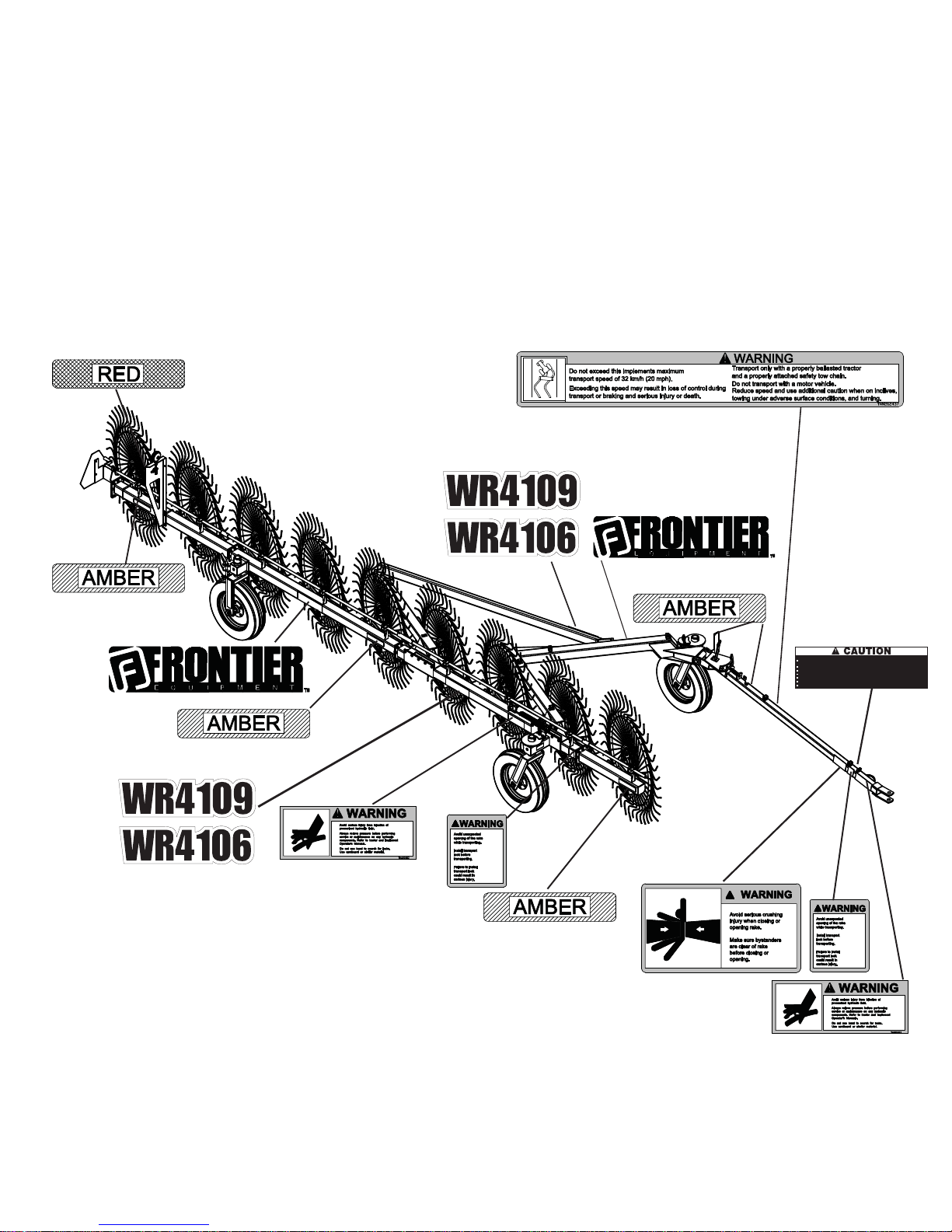
DECALS
4O!VOID3ERIOUS)NJURY
2EAD/PERATORS-ANUALBEFOREOPERATINGSERVICINGORREPAIRINGEQUIPMENT&OLLOWALLSAFETYRULESAND
INSTRUSTIONS-ANUALSAREAVAILABLEFROMYOURSELLINGDEALER
.EVERALLOWRIDERS
+EEPBYSTANDERSAWAYFROMEQUIPMENTDURINGOPERATION
/PERATEFROMTRACTORSEATONLY
+EEPALLSHIELDSINPLACEANDINGOODCONDITION
,OWEREQUIPMENTTOGROUNDSTOPENGINEREMOVEKEYANDSETBRAKEBEFOREDISMOUNTINGTRACTOR
.EVERALLOWCHILDRENORUNTRAINEDPERSONSTOOPERATEEQUIPMENT
4.*$
KEY PART NO. PART NAME QTY SERIAL NO.
1 TNE95848 LABEL WARNING 2 X X
2 TNE95846 LABEL WARNING "AVOID SERIOUS .." 1 2
3 TNC90A0003 YELLOW REFLECTOR 5 7
4 TNC90A0002 RED REFLECTOR 1 X X
5 5TN2451 LABEL WR 4106 2 X
6 5TN1002423JD LABEL CAUTION 1 X X
7 5TN2446 LABEL WR 4109 2 X
8 TN2411 LABEL FRONTIER 2 X X
9 TNA80683 LABEL "HIGH PRESSURE " 2 X X
10 TNN262437 LABEL "MAXIMUM TRANSPORT SPEED" 1 X X
W
W
R
R
4
4
1
1
0
0
9
6
7
2
REMARKS

NUMERICAL INDEX
PART NO. KEY PAGE PART NO. KEY PAGE PART NO. KEY PAGE PART NO. KEY PAGE
5TN1002423JD 6 72 5TNP50QZ012 26 63 TNC90D0002 7 71 TNV20CZ003 23 59
5TN1836001 2 69 5TNP50ZV125 3 61 TNE95846 2 72 TNV20CZ003 6 61
5TN2446 7 72 5TNP50ZV351 4 69 TNE95848 1 72 TNV20CZ003 3 63
5TN2451 5 72 5TNP50ZV354 69 TNL05Z0004 10 71 TNV20CZ003 5 69
5TNC22A0050 4 67 5TNP50ZZ031 23 63 TNL05Z0100 11 71 TNV20CZ003 2 71
5TNC30BZ009 9 61 5TNP50ZZ037 13 61 TNN262437 10 72 TNV20CZ004 28 59
5TNC30DZ007 7 61 5TNP70PV574 15 61 TNP50AV070 4 59 TNV30A0014 17 65
5TNC40AZ002 12 61 5TNV10AZ002 1 69 TNP50BV008 14 65 TNV30AZ004 3 65
5TNC40AZ018 1 63 5TNV10AZ100 22 59 TNP50GZ001 8 59 TNV30AZ014 17 61
5TNC50A0101 67 5TNV10AZ100 5 61 TNP50QZ014 17 59 TNV30BZ004 2 63
5TNC60AS007 22 63 5TNV10AZ101 13 59 TNP50ZV054 3 71 TNV30BZ007 9 65
5TNC60AS007 29 63 5TNV20BZ015 21 61 TNP50ZV169 6 65 TNV35A0003 16 63
5TNC60BV011 63 5TNV20CZ006 3 69 TNP70AV069 8 65 TNV35AZ005 14 63
5TNC60BV011 63 5TNV70AZ001 27 59 TNP70AZ032 31 63 TNV35AZ006 19 63
5TNC70BZ010 28 63 5TNV70AZ007 6 69 TNS10AV003 17 63 TNV40B0010 8 63
5TNC70BZ019 11 61 5TNV70AZ007 9 71 TNS10AV004 19 65 TNV40CZ002 18 61
5TNC70BZ060 14 61 5TNV80A0002 8 61 TNS10BZ001 5
5TNC80AZ002 4 63 5TNV85B0001 19 61 TNS20AZ002 19 59 TNV40CZ009 16 65
5TNC90C0012 1 71 TN2411 8 72 TNS20B0001 9 63 TNV40CZ009 11 67
5TNP20BV003 23 65 TNA80683 9 72 TNS90E0001 6 63 TNV45BZ001 20 59
5TNP25AV002 1
5TNP50AV420 1 59 TNC25A0010 3
5TNP50AV421 2 59 TNC25E0001 1 67 TNV10AZ011 10 59 TNV60A0001 20 65
5TNP50AV422 3 59 TNC25F0010 2 67 TNV10AZ015 2 65 TNV60D0001 18 65
5TNP50BV097 2 61 TNC25L0001 5 67 TNV10AZ046 24 63 TNV60E0001 15 63
5TNP50BV098 21 59 TNC30BZ007 8 67 TNV10AZ126 8 71 TNV60E0004 18 63
5TNP50DV005 24 59 TNC40AZ015 9 67 TNV10BZ001 20 61 TNV80A0001 15 59
5TNP50DV032 13
5TNP50EV001 11 63 TNC45AZ001 12 65 TNV10BZ006 4 65 TNV99AZ001 22 61
5TNP50EV004 12
5TNP50FV005 1 61 TNC50BN060 7 67 TNV20AZ003 10 65
5TNP50GZ005 5 59 TNC70BZ011 10 67 TNV20AZ003 12 67
5TNP50GZ009 7 59 TNC80AZ001 5 63 TNV20AZ004 25 63
5TNP50GZ014 6 59 TNC80CZ001 7 63 TNV20AZ005 18 59
5TNP50GZ018 12 59 TNC90A0002 4
5TNP50HV012 9 59 TNC90A0002 4
5TNP50HV016 25 59 TNC90A0003 3 72 TNV20BZ021 16 61
5TNP50HV016 4 61 TNC90B0003 12
5TNP50HZ008 59 TNC90B0004 5 71 TNV20BZ025 21 63
5TNP50LV001 26 59 TNC90D0001 6 71 TNV20CZ003 14 59
65 TNC25A0004 6 67 TNS95AV001 22 65 TNV50AZ001 10 61
67 TNV10A0121 20 63 TNV50AZ001 13 65
63 TNC40AZ017 11 65 TNV10BZ003 16 59 TNV85A0001 15 65
63 TNC45BZ001 23 61 TNV20AZ003 7 65 TNV99AZ001 10 63
71 TNV20BZ001 11 59
72 TNV20BZ006 21 65
71 TNV20BZ021 27 63
65 TNV40CZ008 30 63
73

INDEX
Page Page
A L
Attaching rake Lubricant
To tractor drawbar ....................... 17 Storage...................................... 31
To tractor hydraulic system …................ 18 Lubrication and Maintenance
As required................................. 35
Lubrication
Annually ................................ 34
B Every 10 hours ........................... 31
Every 100 Hours .......................... 33
Balast, checking ........................... 15 Every 50 hours .......................... 32
M
D
Metric torque values ......................... 55
Detaching rake from tractor . ................. 19
Drawbar shield, making ..................... 15
Drawbar shield, using ....................... 14
Drawbar, tractor, positioning . ................. 14
Operating the rate ........................... 2
F
Field operation, preparing rake for ............. 24
Fittings, flare type tube, tightening ............. 49 Prestarting checks....................... 24
Flare type tube fittings, tightening .............. 49 Product identification number, record............ 5
O
P
4
3
G R
Rake wheels, identifying left-hand and
Grease right-hand . . . ............................ 39
Extreme pressure and multipurpose ….......... 30 Rake, detaching from tractor ...................... 19
Ground pressure, adjusting raking wheel …....... 28 Rake, operating the ............................ 24
Rake, preparing for field operation ............... 24
Rake, preparing for transpsort ................... 21
H Raking wheel ground pressure, adjusting ............. 27
Rake wheel frame install....................... 43
Hitch, three-point, position ................... 15
S
I
Shield, making drawbar ........................... 15
Inch torque values . . ....................... 54 Shield, using drawbar.................................... 14
Inflation, checking tire pressure ............... 16 Spacing, checking wheel…………..………… 15
Serial number, record ............................. 53
Index-1
74

INDEX
Page
Specifications ........................................... 52
Storage
Beginning of season ................................... 40
End of season........................................ 40
Storing lubricants . ...................................... 31
T
Three-point hitch position ................................ 15
Tines, replacing wheel ................................... 39
Tire inflation pressure, checking ............................ 16
Tires, servicing safely .................................. 38
Torque values
Inch............................................... 54
Metric ............................................. 55
Torque, checking wheel nut .............................. 16
Tractor drawbar positioning .............................. 14
Tractor hydraulic system, attaching to ...................... 18
Transport, preparing rake for ............................. 21
Transporting .......................................... 21
Troubleshooting
Hydraulic problems .................................. 36
Raking problems ...................................... 37
Tube fittings, flare type, tightening ....................... 5
3
W
Wheel ground pressure, adjusting raking .................... 28
Wheel nut torque, checking ............................. 16
Wheel spacing, checking ............................... 15
Wheels, rake, identifying left-hand and
right-hand .......................................... 39
Width, adjusting windrow .............................. 27
Width:
Adjusting raking ...................................... 27
Setting working ...................................... 28
Windrow width, adjusting ............................... 27
Index-2
75

NOTES

NOTES

PART NO.
OMUS00W41
 Loading...