

Page 1

OPERATOR’S MANUAL
CARTED RAKE
WR3008
WR3010
WR3012
HSMFG0908
Page 2

TABLE OF CONTENTS
T ABLE OF CONTENTS...............................................................................................INSIDE COVER
WARRANTY & W ARRANTY ST A TEMENT ..........................................................................................1
DEALER PRE-DELIVERY & DELIVERY CHECKLIST.........................................................................3
SPECIFICATIONS..................................................................................................................................5
BOL T TORQUE CHART.........................................................................................................................6
BE ALERT SYMBOL................................................................................................................................7
SAFETY RULES...................................................................................................................................8-9
DANGER - WARNING DECALS........................................................................................................ ...10
OPERA TION WR3008, WR3010 & WR3012.................................................................................11-12
ADJUSTMENTS...............................................................................................................................13-14
OPTIONAL CENTER KICKER WHEEL...............................................................................................15
LUBRICA TION WR3008, WR3010 & WR3012...................................................................................16
DECAL LOCATION................................................................................................................. ...............17
TROUBLE SHOOTING ...........................................................................................................................18
ORDERING P ARTS - ABOUT IMPROVEMENTS..............................................................................19
P ARTS LISTS & DIAGRAMS WR3008, WR3010 & WR3012.....................................................20-27
SERVICE RECORDS...........................................................................................................................28
Page 3

H&S WARRANTY
H&S Manufacturing Co., Inc. (“H&S”) warrants this product to be free from defect in material and
workmanship. Except as noted below, this warranty term is twelve (12) months from the date of delivery of the
product to the original purchaser by an authorized H&S dealer. Under this warranty, H&S will repair or replace, at
its option, any covered part which is found to be defective in material or workmanship during the applicable
warranty term. In no case will the covered repair cost of a part or parts exceed the replacement cost of that part.
Warranty service must be performed by H&S or a dealer authorized by H&S to sell and/or service the product
involved, which will use only new or remanufactured parts or components furnished by H&S. This warranty
includes approved parts and labor to fix the product but does not include, and the purchaser is responsible for,
any service call and/or transportation of the product to and from the dealer’s place of business, for any premium
charged for overtime labor requested by the purchaser, and for any service work not directly related to any defect
covered under this warranty . This warranty includes only those components of the product manufactured by H&S.
Warranty for any component not manufactured by H&S including, but not limited to, engines, batteries, tires, rims,
hydraulic motors, pumps, etc., are covered by the warranty, if any, provided separately by their respective
manufacturers.
This warranty in all its parts, is extended solely to the original purchaser of the product, is terminated upon
any subsequent transfer or sale from or by the original purchaser and extends no third party benefits or rights
whatsoever .
The warranty term for any product used in any commercial, custom, for hire or rental application, is limited to
six (6) months from the date of delivery of the product to the original purchaser by an authorized H&S dealer.
Polybonded (polyethylene and plywood) panels utilized in H&S Manure Spreaders are warrantied, to the
original purchaser, to not wear through and the polyethylene overlay to not tear free of the plywood for the
functional life of the spreader. This specific warranty on polybonded panels includes only replacement of any
defective panel part without any allowance for labor beyond the terms of the general warranty (12 or 6 months),
and is further limited to manure spreaders used to spread normal agricultural manure.
This warranty does not include: (1) Any product that has been altered or modified in ways not approved by
H&S; (2) Depreciation or damage caused by normal wear, misuse, improper or insuf ficient maintenance, improper
operation, accident or failure to follow the product Operator Manual recommendations and product decal
recommendations; (3) Normal maintenance parts and service; (4) Repairs made with parts other than those
available from H&S or performed by anyone other than H&S or a dealer authorized by H&S to sell and/or service
the product involved.
To secure warranty service the purchaser must report the product defect to a dealer authorized by H&S to
sell and/or service the product involved within the applicable warranty term together with evidence of the warranty
start date and make the product available to that dealer within a reasonable period of time.
THERE ARE NO WARRANTIES WHICH EXTEND BEYOND THE DESCRIPTION ON THE FACE OF THIS
WARRANTY. H&S and the companies affiliated with it makes no warranties, representations, or promises,
express or implied, as to the quality or performance or freedom from defect of its products other than those set
forth above and NO IMPLIED WARRANTY OF MERCHANTABILITY, FITNESS OR FITNESS FOR A
PARTICULAR PURPOSE IS MADE. IN NO EVENT WILL THE DEALER, H&S OR ANY COMPANY
AFFILIATED WITH H&S BE LIABLE FOR INCIDENTAL OR CONSEQUENTIAL DAMAGES. The ONLY
REMEDY the purchaser has in connection with the breach of performance of any warranty on H&S products are
those set forth above.
The selling dealer has no authority to make any representation or promise on behalf of H&S, or to modify the
terms or limitations of this warranty in any way .
-1-
Page 4

-2-
Page 5

AFTER COMPLETION, DEALER SHOULD REMOVE AND RETAIN FOR RECORDS
FRONTIER
DEALER PRE-DELIVERY CHECK LIST
After the Carted Rake has been completely set-up, check to be certain it is in correct operating order before
delivering to the customer. The following is a list of points to inspect. Check off each item as you have made
the proper adjustments and found the item operating satisfactorily.
All grease fittings have been lubricated
!
(See lubrication guide in this manual).
All mechanisms are operating trouble free.
!
Rake wheels touch ground in unison when lowered into position.
!
(Rake setting level)
All bolts and fasteners are tight.
!
All decals are in place and legible.
!
(Dealer’s Name) Model Number
Serial Number
(Signature of Pre-Delivery Inspector) (Inspection Date)
DEALER DELIVERY CHECK LIST
This check list that follows is an important reminder of valuable information that should be passed on to the
customer at the time this Carted Rake is delivered.
Check off each item as you explain it to the customer .
This delivery check list, when properly filled out and signed assures the customer that the Pre-delivery
service was satisfactorily performed.
Explain to the customer that the pre-delivery inspection was made.
!
Explain to the customer all the safety precautions they must excercise when operating this unit.
!
Explain raking and windrow width adjustments.
!
Explain to customer that regular lubrication is required for proper operation and long life of
!
machine. Show customer the lubrication section of Owner’s Manual.
Give the customer Owner’s Manual and make sure they read and understand all operating and
!
service instructions.
Record Serial Number on page 19 of this Manual.
!
Date Delivered Dealer’s Name
By
Signature of Original Buyer
-3-
Page 6

-4-
Page 7

FRONTIER WR3008, WR3010, WR3012
CARTED RAKE
Your new Frontier Carted Rake has been manufactured of the finest quality materials and
components. The performance you get from your machine is largely dependent upon how well you
read and understand this manual and apply this knowledge. There is a right and a wrong way to
do everything. Please do not assume that you know how to operate and maintain your Heavy Duty
Wheel Rake before reading this manual carefully . Keep this manual available for ready reference.
SPECIFICA TIONS
WR3008 WR3010 WR3012
Number of Wheels. . . . . . . . . . . . . . 8. . . . . . . . . . . . . . . . .. . . . . . 10. . . . . . . . . . . . . . . . . . . . . . . . . 12
Wheel Diameter . . . . . . . . . . . . . . . . 55”. . . . . . . . . . . . . . . . . . . . . 55”. . . . . . . . . . . . . . . . . . . . . . . . 55”
T eeth per Wheel. . . . . . . . . . . . . . . . 40. . . . . . . . . . . . . . . . . . . . . .40. . . . . . . . . . . . . . . . . . . . . . . . .40
T ooth Diameter . . . . . . . . . . . . . . . . .7mm. . . . . . . . . . . . . . . . . . . .7mm. . . . . . . . . . . . . . . . . . . . . 7mm
Transport Width. . . . . . . . . . . . . . . . 9’6”. . . . . . . . . . . . . . . . . . . . .9’6”. . . . . . . . . . . . . . . . . . . . . .10’6”
Transport Length. . . . . . . . . . . . . . . 13’. . . . . . . . . . . . . . . . . . . . . 15’6”. . . . . . . . . . . . . . . . . . . . . . .18’
Windrow Width Adjustment. . . . . . .4’-6’. . . . . . . . . . . . . . . . . . . . 4’-6’. . . . . . . . . . . . . . . . . . . . . . 4’-6’
Raking Width. . . . . . . . . . . . . . . . . . 16’-20’. . . . . . . . . . . . . . . . . . 18’-22’. . . . . . . . . . . . . . . . . .20’-24’
3 Settings. . . . . . . . . . . . . . . 3 Settings. . . . . . . . . . . . 3 Settings
Weight. . . . . . . . . . . . . . . . . . . . . . . .1125 lbs. . . . . . . . . . . . . . . . .1275 lbs. . . . . . . . . . . . . . .1440 lbs.
Number of Transport Wheels. . . . . 2. . . . . . . . . . . . . . . . . . . . . . .2. . . . . . . . . . . . . . . . . . . . . . . . . . . .2
Center Kicker Wheel. . . . . . . . . . . . N/A. . . . . . . . . . . . . . . . . . . . .Optional. . . . . . . . . . . . . . . .Optional
Rake Wheel Hubs. . . . . . . . . . . . . . . . . . . . . . . . . . . . . . . . . . Tapered Bearings. . . . . . . . . . . . . . . . . . .
Wing Flex. . . . . . . . . . . . . . . . . . . . . . . . . . . . . . . . . . . . . . . . . . . . . .Limited. . . . . . . . . . . . . . . . . . . . . . .
Hitch Jack. . . . . . . . . . . . . . . . . . . . . . . . . . . . . . . . . . . . . . . . . . . . .St andard. . . . . . . . . . . . . . . . . . . . . . .
Tires. . . . . . . . . . . . . . . . . . . . . . . . . . . . . . . . . . . . . . . . . . . . . . . .ST175/80D13. . . . . . . . . . . . . . . . . . . .
NOTE:
Determine right or left side of Carted Rake by viewing it from the rear. If instructions or
parts lists call for hardened bolts see p age 6 to identify .
-5-
Page 8

-6-
Page 9

BE
YOUR SAFETY
ALERT!
THIS SYMBOL IS USED THROUGHOUT THIS BOOK WHENEVER YOUR PERSONAL SAFETY IS
INVOLVED. TAKE TIME TO BE CAREFUL. REMEMBER: THE CAREFUL OPERATOR IS THE BEST
OPERATOR. MOST ACCIDENTS ARE CAUSED BY HUMAN ERROR. CERTAIN PRECAUTIONS
MUST BE OBSERVED TO PREVENT THE POSSIBILITY OF INJURY OR DAMAGE.
TRACTORS
This operator’s manual uses the term “Tractor” when identifying the power source.
IS INVOLVED.
-7-
Page 10

RECOGNIZE SAFETY INFORMA TION
This is the safety-alert symbol. When you see this symbol
on your machine or in this manual, be alert to the potential
for personal injury .
Follow recommended precautions and safe operating
practices.
UNDERST AND SIGNAL WORDS
A signal word- DANGER, WARNING, or CAUTION - is
used with the safety-alert symbol. DANGER identifies the
most serious hazards.
Safety signs with signal word DANGER or WARNING are
typically near specific hazards.
General precautions are listed on CAUTION safety signs.
FOLLOW SAFETY INSTRUCTIONS
Carefully read all safety messages in this manual,
and all safety signs on your machine. Follow all
recommended precautions and safe operating
procedures.
Keep signs in good condition. Immediately replace
any missing or damaged signs.
OBSERVE MAXIMUM TRANSPORT SPEED
The maximum transport speed for this
implement is 32 km/h (20 mph).
Some tractors are capable of operating at speeds that exceed
the maximum transport speed of this implement. Regardless of
the maximum speed capability of the tractor being used to tow
this implement, do not exceed the implement’s maximum
transport speed.
Exceeding the implements maximum transport speed can result in:
" Loss of control of the tractor/implement combination
" Reduced or no ability to stop during braking
" Implement tire failure
" Damage to the implement structure or its components
Use additional caution and reduce speed when towing under
adverse surface conditions, when turning, and when on inclines.
Do not attempt transport if the fully loaded implement weighs more
than 1.5 times the weight of the tractor.
-8-
Page 11

TRACTORS
This operators manual uses the term “Tractor” when identifying the power source.
WARNING
TO PREVENT SERIOUS INJURY OR DEATH
BEFORE YOU ATTEMPT TO OPERATE THIS EQUIPMENT, READ AND STUDY THE FOLLOWING
INFORMATION. IN ADDITION, MAKE SURE THAT EVERY INDIVIDUAL WHO OPERATES OR WORKS
WITH THIS EQUIPMENT, WHETHER FAMILY MEMBER OR EMPLOYEE, IS FAMILIAR WITH THESE
SAFETY PRECAUTIONS.
DO NOT ALLOW PERSONNEL OTHER THAN THE QUALIFIED OPERATOR NEAR THE
MACHINE.
IF RAKE ARMS ARE IN THE RAISED POSITION, MAKE SURE TRANSPORT LOCK PINS
(5HP10WR4) ARE INSTALLED TO LOCK ARMS UP BEFORE CLEANING, WORKING ON, OR
ADJUSTING MACHINE.
DO NOT attempt to perform maintenance or repair with tractor running.
DO NOT step up on machine at any time.
DO NOT allow minors to operate or be near the machine.
Stop the tractor engine, remove ignition key, and allow all mechanisms to stop before cleaning,
working, or adjusting on machine.
Stay clear of rake when raising or lowering main rake beams.
Stay clear of hydraulic lines, they may be under extreme pressure or heat.
For transport and storage, always make sure that the transportation lock pins (5HP10WR4) are
positioned to lock the rake arms in the transport position.
Frontier always takes the operator and his safety into consideration and guards exposed moving
parts for their protection. However, some areas cannot be guarded or shielded in order to assure proper
operation. In addition, the operators manual and decals on the machine itself warn you of further
danger and should be read and observed closely.
Study The Above Safety Rules
ATTENTION - BE ALERT - YOUR SAFETY IS INVOLVED
-9-
Page 12

-10-
Page 13

OPERATION
1. Check for proper assembly and adjustment and make sure that all bolts are tightened. Securely
retighten after a few hours of operation as bolts can loosen up on new machinery. Check wheel bolts
upon delivery and periodically thereafter. Wheel bolts should be tightened at 95 ft./lbs. of torque.
2. Check tires and inflate to recommended pressure (ST175/80D13 to 35 PSI).
3. Adjust the tractor hitch (13 to 17 inches above ground) and attach to tractor with a hitch pin that
has a safety locking device.
4. Remove weight from lift jack. Rotate jack into storage position.
5. Connect hydraulic hose for raising and lowering rake arms.
6. Lubricate the rake completely (See Lubrication Section in This Manual).
7. On all rake wheels, tooth bolts must be torqued to 40 ft./lbs. to help prevent excessive tooth
breakage. Re-torque rake tooth bolts after first 100 acres. (Part No. HPT175) Check
periodically thereafter.
8. Check all bolts on rake after 100 acres. Re-torque if necessary.
NOTE: Determine right or left side of your Carted Rake by viewing it from the rear. If
instructions or parts lists call for hardened bolts, refer to bolt torque chart on page 6.
ADJUSTMENTS
There are four different positions to adjust the hitch on your new Carted Rake. The hitch should be
adjusted so the main rake beams are level, or parallel to the ground. Hitch (A) can be put in the lower set
of holes (B) or the upper set of holes (C). Also hitch (A) can be turned over and be used in holes (B) & (C).
This will give you two additional settings.
A
C
B
-11-
Page 14

OPERATION (Continued)
TRANSPORT LOCKS
There are two (D) transport locks on the Carted Rake. The transport pins (5HP10WR4) lock the rake
beams into the up position for Cleaning or working on the rake and for transport and storage. The pins
should be in the storage position (E) during operation.
D
E
ONE SIDED RAKING
Raking with one side can be accomplished by locking the left rake arm in the transport position (F),
disconnecting the lifting linkage 5HP10WR35 or 5HP12WR5) (G), then putting it into the lifting linkage
storage position (H).
FHG
-12-
Page 15

ADJUSTMENTS
RAKING WIDTH
There are three rake width adjustments on each rake beam. Width on each side can be set independently.
Each rake beam angle can be adjusted independently for multiple raking conditions. Fine tuning is
accomplished by adjusting the threaded ball end attached to the linkage arm.
Windrow Width Adjustments
WINDROW WIDTH
Remove locking pin (A). Remove the jack from jack storage position. Position jack mount tube on top of
rake beam pin (B) with jack foot in position as shown. Windrow width can now be adjusted from 4’ to 6’, in
6” increments on each side of the rake. After the desired windrow width has been reached, re-insert pin (A)
in desired hole. Remove jack and return to storage position.
BA
-13-
Page 16

ADJUSTMENTS (Continued)
DOWN PRESSURE
Down pressure of the rake arms can be adjusted
by adjusting the stop (C) on the top of the spring
located at each end of the main frame. The stop
should be adjusted so there is approximately 1/4
of an inch of threads showing above the jam nut
(D). The carted rake can be adjusted for less
ground pressure by “raising” the stop.
TREAD WIDTH ADJUSTMENT (WR3012 ONLY)
Tread width (wheel spacing) can be adjusted by first jacking up one side of the main frame. Loosen nuts
(4) on the mounting bolts (HP16SV77) (E). The entire wheel assembly now can be positioned as desired.
Retighten nuts evenly. Repeat procedure on the opposite frame.
C
D
E
FLOATATION
The carted rake has been designed to be operated with the hydraulic cylinder in the float position. This
allows the rake beams to “float” up and down without the hydraulic cylinder restricting it’s motion. If your
tractor does not have a float position, you will need the second hose option. If rake is equipped with
second hose option, it is very important transport lock pins are removed prior to attempting to
lower rake arms. Failure to remove pins will result in damage to rake.
NOTE: If 2 hose system is desired, remove vent plug and install hose (3/8” x 145”) (Part No. 5HP10WR10)
between cylinder and tractor.
-14-
Page 17

OPTIONAL CENTER KICKER WHEEL
An optional center kicker wheel is available for the WR3010 and WR3012 carted rake. If the hay is laying
out flat, the extra wheel allows you to raise the hay laying in the center of the rake out of the stubble for
easier pick-up. Attached to the right lifter arm with a cable, the center kicker wheel will raise and lower
when the hydraulics are activated. The center kicker wheel may locked in the up position when not needed.
Down Position
Up Position
-15-
Page 18

LUBRICATION GUIDE
GREASE FITTINGS
There are twelve grease fittings on the Carted Rake. If lubricated properly and often enough, it will prolong
the life of your Carted Rake. Grease daily during normal use and before and after storage and after
power washing. Use a good grade of high quality grease. Make sure that grease comes out around the
shaft on sleeve type bearings. Wipe off excessive grease to prevent accumulation of chaff or grit around
the bearing.
LOCATION
Listed and shown are the description of location and number of grease fittings.
A. (2 ) One on each end fo left side lift linkage
B. (2 ) One on each pivot arm pivot point
C. (4) Two on each of lifter arms
D. (2) One on each horizontal pivot point at the end of lifter arms
E. (2 ) One on each vertical pivot point, rake arm mount
F. (1 ) Center kicker wheel arm (If Equipped)
G. (4 ) One on each rake arm (6 on WR3010 & WR3012)
E
D
C
A
B
A
G
F
-16-
Page 19
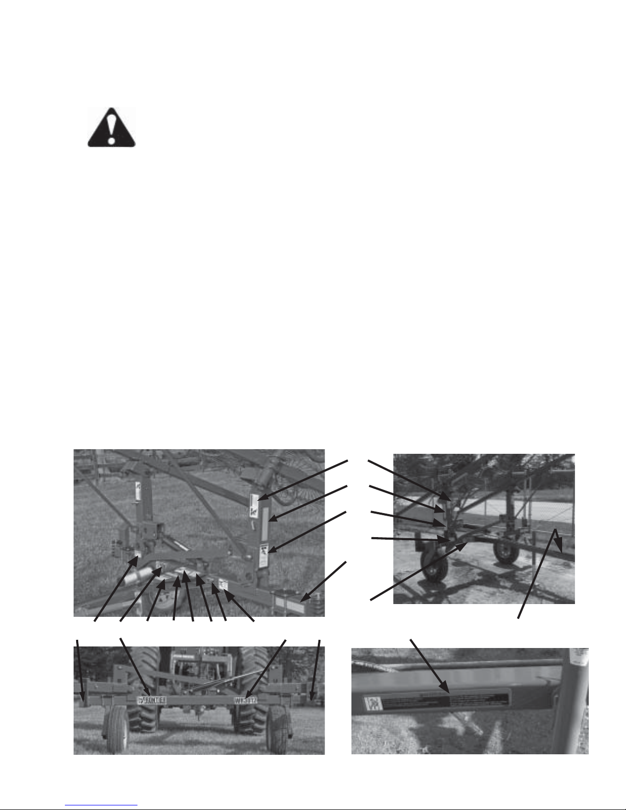
DECAL LOCATION
Your Frontier Carted Rake was manufactured with operator safety in mind. Located on the rake are
various decals to aid in operation, and warn of caution areas. Pay close attention to all decals.
DO NOT REMOVE ANY OF THESE DECALS. IF DECALS ARE LOST, DAMAGED,
OR IF HEAVY DUTY WHEEL RAKE IS REPAINTED, REPLACE DECALS.
REMEMBER: DECALS ARE FOR YOUR PROTECTION AND INFORMATION.
Listed below are the decals on your Carted Rake. These decals may be ordered individually by part
number or by ordering a complete set.
ITEM PART NO. DESCRIPTION
A. 5HP2700A (2) WARNING - Stay Clear of Rake
B. HPFRONTIER13 (2) Frontier Decal
C. 5HP3008WR Frontier Model Decal (WR3008)
5HP3010WR Frontier Model Decal (WR3010)
5HP3012WR Frontier Model Decal (WR3012)
D. 5HP2700B (2) WARNING - Stay Clear of Rake
E. HP2X9RED (2) Red Reflectors
F . HP2X9AMBER (3) Amber Reflectors
G. HP11599 WARNING - Do Not Go Near Leaks
H. HPHS404 Patent Numbers
I. Serial Number
J. HPFRON1 WARNING - Help Avoid Injury
K. 5HP73100A Locking Pin Storage
L. 5HP73100B WARNING - Install Locking Pins
M. 5HP73100C WARNING - Install Locking Pin
N. HP92606 WARNING - Do Not Exceed Transport Speed
O. 5HP51508 DANGER - Avoid Electrical Lines
5HP09083008 Complete Set of Decals (WR3008)
5HP09083010 Complete Set of Decals (WR3010)
5HP09083012 Complete Set of Decals (WR3012)
A
F
D
M
G
B
E L B J K G H I M C E N O
-17-
Page 20

TROUBLE SHOOTING
WARNING
MAKE SURE THAT THE TRACTOR IS SHUT OFF AND THE RAKE CAN NOT MOVE
BEFORE SERVICING THE CARTED RAKE. MAINTENANCE AND REPAIR SERVICE WORK
TO BE PERFORMED BY A QUALIFIED SERVICE PERSON ONLY.
TROUBLE... POSSIBLE CAUSE... POSSIBLE REMEDY...
Rake Lifting Arms Will Not Transport Lock Pins Are In Lock Remove Transport Lock Pins And
Lower Position Place In Storage Position
Hydraulic Coupler Not Coupled Couple Hose To Tractor
To Tractor Properly (See Page #11)
Rake Lifting Arms Hange Up Install Second Hose Kit
And Will Not Lower On Uneven
Terrain
Some Tractors Do Not Operate Install Second Hose Kit
Single Acting Cylinders Well
Rake Lifting Arms Will Not Hydraulic Coupler Not Coupled Couple Hose To Tractor
Raise To Tractor Properly (See Page #11)
Tractor Hydraulics Do Not Tractor Should Have At Least 1500
Sufficient Pressure PSI To Operate Rake
-18-
Page 21

INSTRUCTIONS FOR ORDERING PARTS
All service parts should be ordered through your authorized Frontier dealer. They will be able to
give you faster service if you will provide them with the following
1. Model & Serial number is located on the inside right pole mount, under center frame.
2. All reference to left or right apply to the machine as viewed from the rear.
3. Parts should not be ordered from illustration only. Please order by complete part number.
4. If your dealer has to order parts - give shipping instructions:
VIA truck - large pieces (please specify local truck lines)
VIA United Parcel Service (include full address)
PLEASE RECORD NUMBERS FOR YOUR UNIT FOR QUICK REFERENCE
ABOUT IMPROVEMENTS
FRONTIER IS CONTINUALL Y STRIVING TO IMPROVE IT’S PRODUCTS
We must therfore, reserve the right to make improvements or changes whenever it becomes practical to do so
without incuring any obligation to make changes or additions to the equipment previously sold.
-19-
Page 22

FIGURE 1
-20-
Page 23

FIGURE 1
FRONTIER MODEL WR3008, WR3010 & WR3012
CARTED RAKE
ITEM WR3008 WR3010 WR3012 DESCRIPTION
1. 5HP10WR22 “ “ Rake Arm
2. - 5HP10WR23 - Single Rake Arm
3. 5HP8WR1 5HP10WR24 5HP12WR2 Right Rake Beam
4. 5HP8WR1 5HP10WR25 5HP12WR3 Left Rake Beam
5. 5HP8WR9 5HP10WR26 5HP12WR4 Main Frame
6. 5HP8WR7 5HP10WR27 “ Right Lifter Arm
7. 5HP8WR6 5HP10WR28 “ Left Pivot Arm Housing
8. 5HP10WR29 “ “ Pole
9. 5HP10WR30 “ “ Hitch
10. 5HP8WR8 5HP10WR31 “ Link Rod
11. 5HP10WR9 “ “ Adjusting Rod
12. 5HP8WR5 5HP10WR34 “ Slide Arm
13. 5HP10WR35 “ 5HP12WR5 Lifting Linkage
14. 5HP10WR7 “ “ Rake Arm Pins
15. 5HP10WR36 “ “ Right Pivot Bracket
16. 5HP10WR37 “ “ Left Pivot Bracket
17. 5HP10WR6 “ “ Rake Beam Pin
18. 5HP10WR8 “ “ Pivot Thrust Washer
19. HPBFR223 “ “ Jack
20. 5HP10WR16 “ “ Spring Adjustment
21. 5HP10WR46 “ “ Spring Bottom
22. 5HP10WR47 “ 5HP12WR1 Spring
23. 5HP10WR3 “ “ Spring Clamp
24 . HP16SV77 “ “ 1/2” x 6” Bolt GR.5
25. - - 5HP10WR38 Axle Plate
26. 5HP10WR32 “ “ Right Axle
27. 5HP10WR33 “ “ Left Axle
28. 5HPCAT5 “ “ Seal
29. 5HPCAT6 “ “ Inner Bearing
30. 5HPCAT7 “ “ Inner Race
31. 5HPCAT128A “ “ Hub Stud
32. HPCAT14 “ “ Hub Nut
33. 5HP10WR49 “ “ Ground Wheel Hub
34 . HPCAT9 “ “ Outer Race
35. HPCAT10 “ “ Outer Bearing
36 . HPBFR63 “ “ Washer
37 . HPBFR64 “ “ Nut
38. HPCAT13 “ “ Hub Cap
39. 5HP10WR11A “ “ 2-1/2” x 16” Cylinder
40. 5HP10WR4 “ “ Transport Pins
41. 5HP10WR5 “ “ Slide Lock Pin
42 . HPBFR36 “ “ Spindle
43. HPT163 “ “ Seal
NOTE: * (MEANS SHOWN)
- (MEANS NOT USED ON THIS MODEL)
“ (MEANS SAME P ART NO. AS PREVIOUS MODEL)
-21-
Page 24
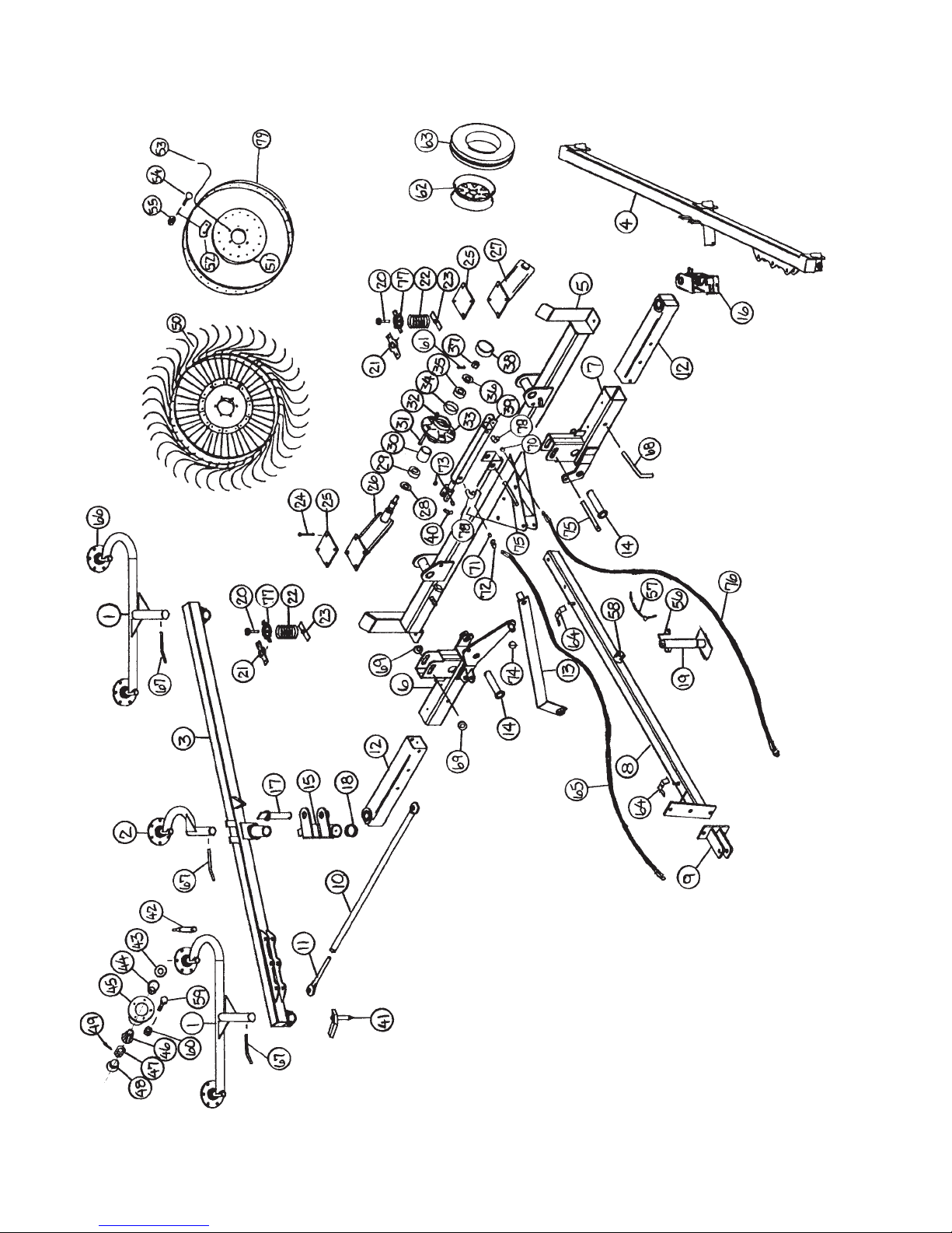
FIGURE 1
-22-
Page 25

FIGURE 1
FRONTIER MODEL WR3008, WR3010 & WR3012
CARTED RAKE
ITEM WR3008 WR3010 WR3012 DESCRIPTION
44. HPT164 “ “ Inner Bearing
* HPT165 “ “ Inner Race
45 . HPBFR32 “ “ Rake Wheel Hub
46. HPT170 “ “ Outer Bearing
* HPT171 “ “ Outer Race
47. HPT172 “ “ Nut
48. HPT173 “ “ Hub Cap
49. HPT169 “ “ Cotter Pin
50 . HPBFR31 “ “ RH Rake Wheel
* HPT174 “ “ LH Rake Wheel
51. HPT179 “ “ Rake Wheel Center
52. HPT178 “ “ Rake Tooth Clip
53. HPT176 “ “ Rake Wheel Tooth
54. HPT175 “ “ 10mmx25mm Carriage Bolt
55. HPT166 “ “ 10mm Nut
56 . HPBFR3 “ “ Jack Handle
57 . HPBFR4 “ “ Jack Pin & Chain
58. HP12N14 “ “ Jack Mount
59. HPT168 “ “ 10mmx25mm Bolt
60. HPT166 “ “ 10mm Nut
61. HPT37 “ “ Cotter Pin
62. 5HPCAT195 “ “ 13 x 4-1/2 Wheel
63. 5HPCAT198 “ “ ST175x80D13 Tire
64 . HP23N67 “ “ Hose Hol d e r
65. 5HP10WR10 “ “ 3/8”x145” Hose
66. 5HPBFR76 “ “ Hub - Complete
67. 5HP10WR13 “ “ 3” Pin
68. 5HP10WR14 “ “ 5” Pin
69. HP16SV136 “ “ Washer
70 . HPBFR70 “ “ Vent Plug
71. HPBFR120 “ “ Orifice
72 . HPBFR12 “ “ Male Adapter Union
* HPBFR617 “ “ Adapter Union & Orifice
73 . HPBFR33 “ “ Washer
74. HPF56 “ “ Clip Pin
75. 5HPLW55 “ “ Pin
77. 5HP10WR15 “ “ Spring Holder
79. HPT177 “ “ Outer Ring
OPTIONAL DOUBLE ACTING CYLINDER:
76. 5HP10WR10 “ “ 3/8”x145” Hose
78 . - - HP23N234 90° Street Elbow
NOTE: #70 Vent Plug Not Used on Double Acting Cylinder
NOTE: * (MEANS NOT SHOWN)
- (MEANS NOT USED ON THIS MODEL)
“ (MEANS SAME PREVIOUS PART NO.)
-23-
Page 26

FIGURE 2
-24-
Page 27

FIGURE 2
FRONTIER MODEL WR3010 & WR3012
OPTIONAL KICKER WHEEL
ITEM WR3010 WR3012 DESCRIPTION
1. 5HP10WR41 “ Kicker Arm
2. 5HP10WR39 “ Mounting Bracket Top
3. 5HP10WR20 “ Mount
4. 5HP10WR19 “ Pulley Mount
5. HPBFR292 “ Poly Pulley
6. HPST81 “ Spacer
7. 5HP10WR40 “ Pivot Mount
8. 5HP10WR18 “ 5/16”x3” Bolt GR.5
9. 5HPF87 “ “S” Hook
10. HPES14 “ Cable Protector
11. HPES5 “ Crimp On Clamp
12. 5HP12WR6 “ Cable (57”)
13. 5HPT19 “ 3/8” x 2” Bolt GR.5
14. HPES10 “ I-Bolt (5/16” x 4” Overall)
15. HPBFR110 “ Spring
16. HPT163 “ Seal
17. HPT164 “ Inner Bearing
18. HPT165 “ Inner Race
19. HPT168 “ Hub Bolt
20 . HPBFR32 “ Hub
21. HPT166 “ Hub Nut
22. HPT171 “ Outer Race
23. HPT170 “ Outer Bearing
24. HPT172 “ Nut
25. HPT169 “ Cotter Pin
26. HPT173 “ Hub Cap
27. 5HP10WR17 “ 48” Kicker Wheel
28. HPT179 “ Rake Wheel Center
29. HPT178 “ Rake Tooth Clip
30. 5HP10WR42 “ Rake Wheel Tooth
31. HPT168 “ 10mmx25mm Bolt
32. HPT166 “ 10mm Lock Nut
33. HP3G22 “ Roll Pin
34. HP12V45 “ 1/2”x1-1/2” Bolt GR.5
35. HPS99 “ “O” Ring
36 . HPG16 “ Bro nz e Bus hi n g
37. HPBFR230 “ Bearing Spacer
38. HPBFR221 “ Poly Washer
39. 5HP10WR44 “ Chain (5 Links)
40. HPBFR295 “ Snap Hook
41. 5HP10WR43 “ 3/8”x1” Bolt
42. HPBFR229 “ Washer
43. HPT177 “ Outer Ring
NOTE: “ (MEANS SAME AS PREVIOUS PART NO.)
-25-
Page 28

FIGURE 3
FIGURE 3
FRONTIER MODEL WR3010 & WR3012
HYDRAULIC CYLINDER
ITEM WR3008 WR3010 WR3012 DESCRIPTION
1. 5HPT181A “ “ Clevis Cap
2. 5HPT182A “ “ Rod Cap
3. 5HPT183 “ “ Piston
4. HP23N145A “ “ Rod
5. 5HP10WR45 “ “ Cylinder Tube
6. HP23N147 “ “ T ie Rod
7. HP23N148 “ “ Piston Nut
8. HP23N149 “ “ Plug
9. HP23N150A “ “ Rod Clevis
10. 5HPT187 “ “ Seal Kit
11. 5HP10WR11A “ “ Complete Cylinder
-26-
Page 29

FIGURE 4
1 2 3 4 5 6
9
7 8 10 11
12
13 14 15
FIGURE 3
FRONTIER MODEL WR3008, WR3010 & WR3012
DECALS
ITEM PART NO. DESCRIPTION QTY.
1. 5HP2700B WARNING - Stay Clear of Rake Decal 2
2. 5HP73100B WARNING - Install Locking Pins Decal 1
3. 5HP2700A WARNING - Stay Clear of Rake Decal 2
4. 5HP73100C WARNING - Install Locking Pin Decal 1
5. HP11599 WARNING - Do Not Go Near Leaks Decal 1
6. HPFRON1 WARNING - Help Avoid Injury Decal 1
7. HP2X9RED Red Reflector Decal 2
8. HP2X9AMBER Amber Reflector Decal 3
9. 5HP73100A Locking Pin Storage Decal 1
10 . HPHS404 Pat en t Nu mb er De cal 1
11. HP92606 WARNING - Do Not Exceed Transport Speed Decal 1
12. 5HP3008WR Frontier Model Decal (WR3008) 1
13. 5HP3010WR Frontier Model Decal (WR3010) 1
14. 5HP3012WR Frontier Model Decal (WR3012) 1
15. HPFRONTIER13 Frontier Decal 2
16. 5HP51508 DANGER - Avoid Electrical Lines Decal 1
5HP09093008 Complete Set of Decals (WR3008) 1
5HP09083010 Complete Set of Decals (WR3010) 1
5HP09083012 Complete Set of Decals (WR3012) 1
16
-27-
Page 30

SERVICE / MAINTENANCE RECORD
DATE DESCRIPTION NOTES
-28-
Page 31

2608 S. Hume A ve.
P.O. Box 768 - Telephone (715) 387-3414
F AX (715) 384-5463
MARSHFIELD, WI 54449
Page 32

 Loading...