

Page 1
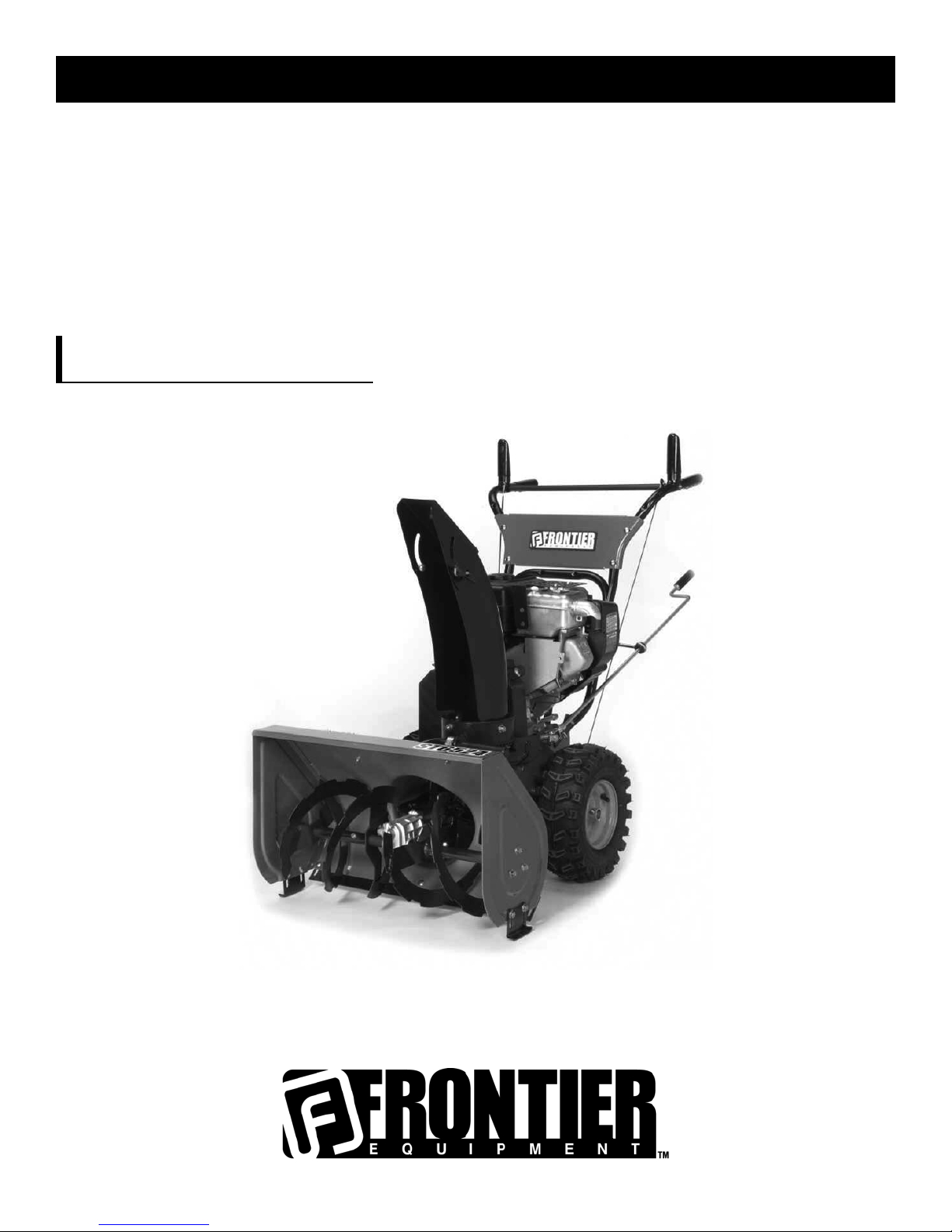
OPERATOR’S MANUAL
SNOWTHROWERS
ST7526
MT1735091
Rev. 00 (5/21/07)
TP 100-4612-00-IS-T
Page 2

Congratulations on your purchase of a Frontier Snowthrower. It has been designed, engineered and manufactured to give you the best
possible dependability and performance. However, like all mechanical products, your machine will occasionally require adjustment and
maintenance. This handbook should be read before operating or performing any adjustments on your machine.
The instructions in this Operator’s Manual are written for a person with some mechanical ability. Like most service books, not all the steps
are described. Steps on how to loosen or tighten fasteners are steps anyone can follow with some mechanical ability. Read and follow
these instructions before you use the unit.
Know your product: If you understand the unit and how the unit operates, you will get the best performance. As you read this manual,
compare the illustrations to the unit. Learn the location and the function of the controls. To help prevent an accident, follow the operating
instructions and the safety rules. Keep this manual for future reference.
IMPORTANT: Many units are not assembled and are sold in cartons. It is the responsibility of the owner to make sure the assembly instructions in this manual are exactly followed. Other units are purchased in an assembled condition. On assembled units, it is the responsibility of the owner to make sure the unit is correctly assembled. The owner must carefully check the unit according to the instructions in this
manual before it is first used.
The warranty, found in this manual, details the coverage and limitations of this product. Registration of the warranty is necessary and
must be preformed by the dealer within sixty (60) days from the date of retail sale or delivery. The Warranty Registration Form is located on the Frontier website.
RESPONSIBILITY OF THE OWNER
The responsibility of the owner is to follow the instructions below.
1. Carefully read and follow the rules for safe operation.
2. Follow all the assembly instructions.
3. Inspect the unit.
4. Make sure that the operator of the unit knows how to correctly use all standard and accessory equipment.
5. Operate the unit only with guards, shields, and other safety items in place and working correctly.
6. Correctly adjust the unit.
7. Service the unit only with authorized or approved replacement parts.
8. Complete all maintenance on the unit.
PRODUCT INFORMATION
The owner must be certain that all the product information is included with this unit.
This information includes the INSTRUCTION BOOKS, the REPLACEMENT PARTS
and the WARRANTIES. This information must be included to make
sure state laws and other laws are followed.
Read And Keep This Book For
Future Reference. This Book Contains Important Information On:
SAFETY
, ASSEMBL
Y, OPERATION AND MAINTENANCE.
INTRODUCTION
2
Page 3
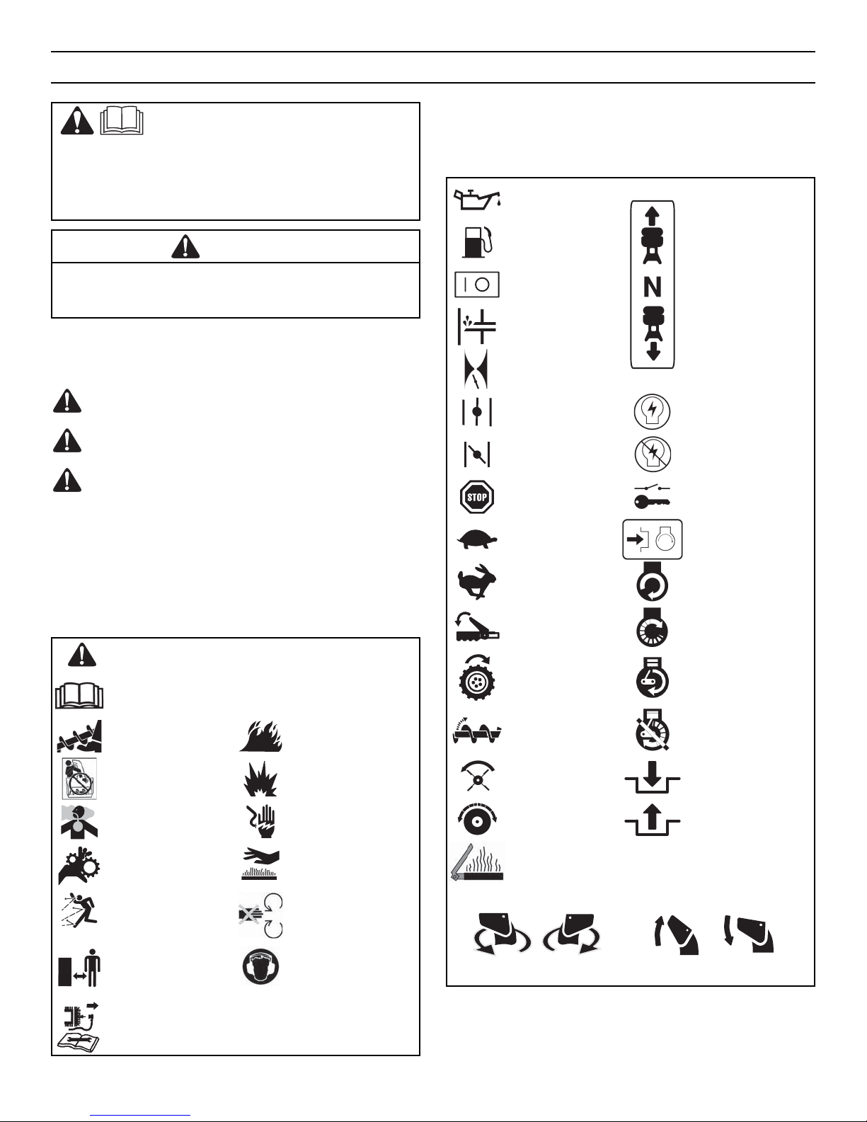
A signal word (DANGER, WARNING, or CAUTION) is used with the alert
symbol to indicate the likelihood and the potential severity of injury. In
addition, a hazard symbol may be used to represent the type of hazard.
DANGER indicates a hazard which, if not avoided, will result in
death or serious injury.
WARNING indicates a hazard which, if not avoided, could result in
death or serious injury.
CAUTION indicates a hazard which, if not avoided, might result in
minor or moderate injury.
CAUTION, when used without the alert symbol, indicates a
situation that could result in damage to the equipment.
Hazard Symbols and their Meanings
These symbols are used on your equipment and defined in your operating
manual. Review and understand the meanings. The use of one of these
symbols combined with a signal word will alert you to potential hazards
and how to avoid them.
Operating Symbols and their Meanings
These symbols are used on your equipment and defined in your operating
manual. It is important that you review and understand the meanings.
Failure to understand the symbols might result in harm to you.
RULES FOR SAFE OPERATION
3
This manual contains safety information to make you
aware of the hazards and risks associated with
snowthrowers, and how to avoid them. The snowthrower is designed
and intended for removal of snow, and should not be used for any other
purpose. It is important that you read and understand these
instructions, and anyone operating the equipment read and understand
these instructions.
WARNING
The engine exhaust from this product contains chemicals known to the
State of California to cause cancer, birth defects, or other reproductive
harm.
Safety Alert – Identifies safety information about hazards
that can result in personal injury.
Operator’s Manual – Read and understand before
performing any activity or running equipment.
Rotating auger Fire
Rotating impeller Explosion
Toxic fumes Shock
Rotating gears Hot surface
Thrown objects
Never reach into
rotating parts.
Keep a safe distance
from the equipment.
Recommended ear
protection for extended
use.
Shut off engine and remove spark plug connector before
performing maintenance or repair work.
Oil
Fuel Forward
On Off Neutral
Primer bulb Reverse
Throttle
Choke off Ignition On
Choke on Ignition Off
Stop Ignition Key
Slow
Push to engage
electric start
Fast Electric Start
Engage Engine Start
Traction Engine Run
Auger Collector Engine Off
Auger Clutch Engage
Drive Clutch Disengage
Heated Grips
Discharge Chute Chute Deflector
LEFT RIGHT UP DOWN
Page 4

IMPORTANT: Safety standards require operator presence control to
minimize the risk of injury. Your snowthrower is equipped with such
controls. Do not attempt to defeat the function of the operator presence
control under any circumstances.
Training
1. Read, understand, and follow all instructions on the machine and in
the manuals before operating this unit. Be thoroughly familiar with
the controls and the proper use of the equipment. Know how to stop
the unit and disengage the controls quickly.
2. Never allow children to operate the equipment. Never allow adults to
operate the equipment without proper instruction.
3. Keep the area of operation clear of all persons, particularly small
children, and pets.
4. Exercise caution to avoid slipping or falling especially when operating
in reverse.
Preparation
1. Thoroughly inspect the area where the equipment is to be used and
remove all doormats, sleds, boards, wires, and other foreign objects.
2. Disengage all clutches and shift into neutral before starting the
engine (motor).
3. Do not operate the equipment without wearing adequate winter outer
garments. Wear footwear that will improve footing on slippery
surfaces. Avoid loose fitting clothing that can get caught in moving
parts.
4. Handle fuel with care; it is highly flammable.
a. Use an approved fuel container.
b. Never add fuel to a running engine or hot engine.
c. Fill fuel tank outdoors with extreme care. Never fill fuel tank
indoors. Replace fuel cap securely and wipe up spilled fuel.
d. Never fill containers inside a vehicle or on a truck or trailer bed
with a plastic liner. Always place containers on the ground, away
from your vehicle, before filling.
e. When practical, remove gas-powered equipment from the truck or
trailer and refuel it on the ground. If this is not possible, then refuel
such on a trailer with a portable container, rather than from a
gasoline dispenser nozzle.
f. Keep nozzle in contact with the rim of the fuel tank or container
opening at all times, until refueling is complete. Do not use a
nozzle lock-open device.
g. Replace gasoline cap securely and wipe up spilled fuel.
h. If fuel is spilled on clothing, change clothing immediately.
5. Use extension cords and receptacles as specified by the
manufacturer for all units with electric drive motors or electric
starting motors.
6. Adjust the collector housing height to clear gravel or crushed rock
surfaces.
7. Never attempt to make any adjustments while the engine (motor) is
running (except when specifically recommended by manufacturer).
8. Let engine (motor) and snowthrower adjust to outdoor temperatures
before starting to clear snow.
9. Always wear safety glasses or eye shields during operation or while
performing an adjustment or repair to protect eyes from foreign
objects that may be thrown from the machine.
Operation
1. Do not put hands or feet near or under rotating parts. Keep clear of
the discharge opening at all times.
2. Exercise extreme caution when operating on or crossing gravel
drives, walks or roads. Stay alert for hidden hazards or traffic.
3. After striking a foreign object, stop the engine (motor), remove the
wire from the spark plug, disconnect the cord on electric motors,
thoroughly inspect snowthrower for any damage, and repair the
damage before restarting and operating the snowthrower.
4. If the unit should start to vibrate abnormally, stop the engine (motor)
and check immediately for the cause. Vibration is generally a warning
of trouble.
5. Stop the engine (motor) whenever you leave the operating position,
before unclogging the collector/impeller housing or discharge chute
and when making any repairs, adjustments, or inspections.
6. When cleaning, repairing, or inspecting, make certain the collector/
impeller and all moving parts have stopped. Disconnect the spark
plug wire and keep the wire away from the spark plug to prevent
accidental starting.
7. Do not run the engine indoors, except when starting the engine and
for transporting the snowthrower in or out of the building. Open the
outside doors; exhaust fumes are dangerous (containing CARBON
MONOXIDE, an ODORLESS and DEADLY GAS).
8. Exercise extreme caution when operating on slopes. Do not attempt
to clear steep slopes.
9. Never operate the snowthrower without proper guards, plates, or
other safety protective devices in place and working.
10. Never direct the discharge toward people or areas where property
damage can occur. Keep children and others away.
11. Do not overload the machine capacity by attempting to clear snow at
too fast a rate.
12. Never operate the machine at high transport speeds on slippery
surfaces. Look behind and use care when operating in reverse.
13. Disengage power to the collector/impeller when snowthrower is
transported or not in use.
14. Use only attachments and accessories approved by the manufacturer
of the snowthrower (such as cabs, tire chains, etc.).
15. Never operate the snowthrower without good visibility or light.
Always be sure of your footing and keep a firm hold on the handles.
Walk, never run.
16. Never touch a hot engine or muffler.
RULES FOR SAFE OPERATION
4
WARNING: This machine is capable of amputating hands and feet and throwing objects. Read these safety rules and follow them closely.
Failure to obey these rules could result in loss of control of unit, severe personal injury or death to you, or bystanders, or damage to property
or equipment. The triangle in text signifies important cautions or warnings which must be followed.
Safe Operation Practices for Snowthrowers
As Recommended By: American National Standards Institute (ANSI)
Page 5

17. Never operate the snowthrower near glass enclosures, automobiles,
window wells, drop-offs, and the like without proper adjustment of
the snow discharge angle.
18. Never direct discharge at bystanders or allow anyone in front of the
unit.
19. Never leave a running unit unattended. Always disengage the auger
and traction controls, stop engine, and remove keys.
20. Do not operate the unit while under the influence of alcohol or drugs.
21. Keep in mind the operator is responsible for accidents occurring to
other people or property.
22. Data indicates that operators, age 60 years and above, are involved
in a large percentage of power equipment-related injuries. These
operators should evaluate their ability to operate the unit safely
enough to protect themselves and others from injury.
23. DO NOT wear long scarves or loose clothing that could become
entangled in moving parts.
24. Snow can hide obstacles. Make sure to remove all obstacles from the
area to be cleared.
Children
Tragic accidents can occur if the operator is not alert to the presence of
children. Children are often attracted to the unit and the operating activity.
Never assume that children will remain where you last saw them.
1. Keep children out of the area and under the watchful care of another
responsible adult.
2. Be alert and turn off if children enter the area.
3. Never allow children to operate the unit.
4. Use extra care when approaching blind corners, shrubs, trees, or
other objects that may obscure vision.
Clearing A Clogged Discharge Chute
Hand contact with the rotating impeller inside the discharge chute is the
most common cause of injury associated with snowthrowers. Never use
your hand to clean out the discharge chute.
To clear the chute:
1. SHUT OFF THE ENGINE.
2. Wait 10 seconds to be sure the impeller blades have stopped
rotating.
3. Always use a clean-out tool, not your hands.
Service, Maintenance And Storage
1. Check shear bolts and other bolts at frequent intervals for proper
tightness to be sure the equipment is in safe working condition.
2. Never store the machine with fuel in the tank inside a building where
ignition sources are present such as hot water and space heaters, or
clothes dryers. Allow the engine to cool before storing in any
enclosure.
3. Always refer to operator’s manual for important details if the
snowthrower is to be stored for an extended period.
4. Maintain or replace safety and instruction labels as necessary.
5. Run the machine a few minutes after throwing snow to prevent
freeze-up of the collector/impeller.
6. If fuel is spilled, do not attempt to start the engine but move the
machine away from the area of spillage and avoid creating any source
of ignition until fuel vapors have dissipated.
7. Always observe safe refueling and fuel handling practices when
refueling the unit after transportation or storage.
8. Always follow the engine manual instructions for storage
preparations before storing the unit for both short and long term
periods.
9. Always follow the engine manual instructions for proper start-up
procedures when returning the unit to service.
10. Maintain or replace safety and instruction labels as necessary.
11. Keep nuts and bolts tight and keep equipment in good condition.
12. Never tamper with safety devices. Check their proper operation
regularly and make necessary repairs if they are not functioning
properly.
13. Components are subject to wear, damage, and deterioration.
Frequently check components and replace with manufacturer’s
recommended parts, when necessary.
14. Check control operation frequently. Adjust and service as required.
15. Use only factory authorized replacement parts when making repairs.
16. Always comply with factory specifications on all settings and
adjustments.
17. Only authorized service locations should be utilized for major service
and repair requirements.
18. Never attempt to make major repairs on this unit unless you have
been properly trained. Improper service procedures can result in
hazardous operation, equipment damage and voiding of
manufacturer’s warranty.
19. Check shear bolts (pins) and other bolts at frequent intervals for
proper tightness to be sure the equipment is in safe working
condition.
Emissions
1. Engine exhaust from this product contains chemicals known, in
certain quantities, to cause cancer, birth defects, or reproductive
harm.
2. If available, look for the relevant Emissions Durability Period and Air
Index information on the engine emissions label.
Ignition System
1. This spark ignition system complies with Canadian ICES-002.
RULES FOR SAFE OPERATION
5
Page 6

HAZARD SYMBOLS AND THEIR MEANINGS .............................................. 3
OPERATING SYMBOLS AND THEIR MEANINGS ........................................... 3
RULES FOR SAFE OPERATION............................................................... 4
SAFETY DECALS ............................................................................... 7
WARRANTY ..................................................................................... 8
OWNER’S INFORMATION ..................................................................... 8
ASSEMBLY ...................................................................................... 9
TOOLS REQUIRED FOR ASSEMBLY........................................................................ 9
CONTENTS OF SHIPPING CARTON......................................................................... 9
PARTS BAGS CONTENTS........................................................................................ 9
UNPACKING ............................................................................................................ 10
UPPER HANDLE AND CRANK ASSEMBLY .............................................................. 11
CHECK THE CABLES ............................................................................................... 11
HOW TO SET THE LENGTH OF THE CABLES.......................................................... 11
SNOW CHUTE ASSEMBLY ...................................................................................... 12
SHIFTER LEVER KNOB ASSEMBLY......................................................................... 12
CHECK THE TIRES .................................................................................................. 12
OPERATION ..................................................................................... 13
ENGINE AND SNOWTHROWER CONTROLS ........................................................... 13
SNOWTHROWER OPERATION................................................................................ 14
WHEEL LOCK OUT PIN ........................................................................................... 15
HOW TO SET THE DRIFT CUTTERS........................................................................ 16
BEFORE STARTING ENGINE.................................................................................... 17
CHECK THE ENGINE................................................................................................ 17
FILL GAS ................................................................................................................. 17
BEFORE STOPPING THE ENGINE............................................................................ 18
TO STOP ENGINE.................................................................................................... 18
TO START ENGINE .................................................................................................. 18
FROZEN STARTER................................................................................................... 20
HOW TO CLEAR A CLOGGED DISCHARGE CHUTE................................................. 20
HOW TO USE THE CLEAN-OUT TOOL..................................................................... 20
OPERATING TIPS.................................................................................................... 21
SERVICE RECOMMENDATIONS .............................................................. 22
MAINTENANCE ................................................................................. 23
SNOWTHROWER .................................................................................................... 23
LUBRICATION AT STORAGE ................................................................................... 23
LUBRICATION EVERY 25 HOURS ........................................................................... 24
ENGINE ................................................................................................................... 25
HOW TO REMOVE THE SNOW HOOD..................................................................... 26
AUGER HOUSING HEIGHT ADJUSTMENT .............................................................. 27
BELT ADJUSTMENT ................................................................................................ 28
HOW TO REPLACE THE BELTS ............................................................................... 29
BELT GUIDE ADJUSTMENT..................................................................................... 32
TRACTION DRIVE CABLE ADJUSTMENT ................................................................ 33
HOW TO ADJUST OR REPLACE THE FRICTION WHEEL......................................... 34
AUGER SHEAR BOLT REPLACEMENT..................................................................... 37
TO ADJUST OR REPLACE THE SPARK PLUG......................................................... 37
STORAGE........................................................................................ 38
TROUBLE SHOOTING CHART................................................................. 39
REPLACEMENT PARTS ........................................................................ 42
SPECIFICATIONS ............................................................................... 43
TABLE OF CONTENTS
6
Page 7
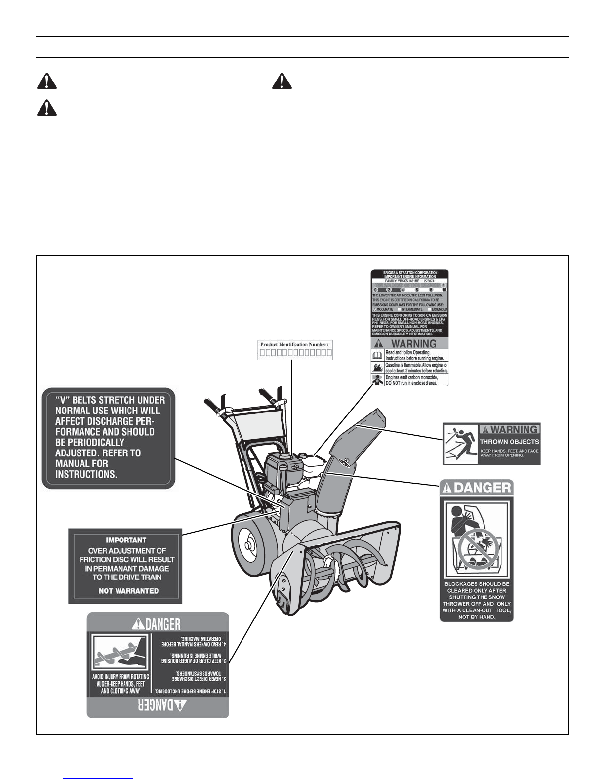
WARNING: If safety decals are damaged or missing,
replace immediately.
Look for this symbol to indicate important safety precautions. This symbol indicates: “Attention! Become
Alert! Your Safety Is At Risk.”
Before operation of your snowthrower, read the safety decals as
shown on your snowthrower. The cautions and warnings are for
your safety. To avoid a personal injury or damage to your
snowthrower, understand and follow all safety decals. If you have
any questions regarding the meaning or how to comply with the
instructions, do not operate until you understand the purpose for
the warning or danger given in the safety decal. If you do not understand the meaning, then thoroughly read all safety and operation
instructions in this OPERATOR’S MANUAL or contact your local
dealer.
If any safety decals become worn or damaged and cannot be read,
order replacement decals from your local dealer.
Identifying Your Snowthrower
The snowthrower has two (2) identifying numbers: (1) unit model
number: (2) unit serial number. The two preceding numbers are
required to insure that the proper replacement parts are obtained
when required. If you have any questions concerning parts, service, or technical data, contact the dealer where the unit was purchased. For complete warranty information refer to the warranty in
the OWNER’S INFORMATION section of this manual.
SAFETY DECALS
7
Figure 1
Page 8

FRONTIER EQUIPMENT LIMITED WARRANTY POLICY
Effective June 1, 2006
What is covered:
Briggs & Stratton Power Products warrants to the original purchaser that each new product or service replacement part is free from defects in material
and workmanship, under normal residential use and service, for the periods listed. The warranty period begins at the purchase date and is subject to the
conditions provided in this policy. Subject to the terms noted in this Limited Warranty Policy Briggs & Stratton will, at its option, repair or replace at no
cost to the original purchaser any part covered by this Limited Warranty Policy during the applicable warranty period. Electrical components and normal
wear components are warranted to be free of material and workmanship defects at the time of sale. This warranty covers the cost of the part only.
However, if the part was installed by an authorized John Deere/Frontier service center, the cost of the part as well as the labor to install will be covered.
What is not covered:
This warranty does not cover normal wear items. Normal wear items are defined as drive belts, drive discs, shear pins, tires, and headlights. These parts
are warranted to be free from defects in materials and workmanship as delivered with the product, or as sold as over the counter service replacement
parts. Any claim for repair or replacement of normal wear parts must be made within 30 days of the date of purchase. No claims involving damage from
material use, abuse, or misuse will be honored. This warranty does not cover third party produced accessories or components (such as electric starters,
engines, etc.) that are warranted through the original manufacturer except as noted in the chart below. These third party items are warranted and serviced
through the manufacturer’s own authorized field service outlets. Consult the manufacturer’s warranty documentation for coverage related to these
particular items. If you are uncertain whether your unit contains one or more of these parts, consult your dealer prior to purchase.
This warranty does not cover transportation of the unit to or from a repair center. It does not cover the cost of non-Briggs service parts or damages
resulting from their use. This warranty does not apply to any unit that has been tampered with, altered, misused, abused, or used for rental or
commercial/professional uses. The duration for rental or commercial/professional use is noted below. The warranty does not cover minor mechanical
adjustments which are not due to any defect in material or workmanship. For assistance in making adjustments, refer to the operator’s manual.
Terms & Conditions
To make a claim under this warranty, return the unit along with your proof of purchase to an authorized John Deere/Frontier dealer (Briggs & Stratton
authorized). If you return the entire unit, the service center will repair the unit. Contingent on receipt of prior authorization, you may return the defective
part only for repair or replacement of the defective part. To locate the nearest John Deere/Frontier dealer, check your local yellow page listings or go to
www.johndeere.com.
No other warranty or implied warranty by the manufacturer exists except where required by law.
Briggs & Stratton’s liability arising out of warranties, representations, instructions, or defects from any cause shall be limited exclusively to repair or
replacing parts under the conditions in this warranty, and in no event will Briggs & Stratton be liable for incidental or consequential damages. Some states
do not allow the exclusion or limitation of incidental or consequential damages, so the above limitation or exclusion may not apply to you. This warranty
gives you specific rights that vary from state to state.
FOR YOUR RECORDS
DATE PURCHASED: ____________________
MODEL NO: __________________________
SERIAL NO: __________________________
STORE WHERE PURCHASED: ____________
ADDRESS: ___________________________
CITY: __________________ STATE: ______
TELEPHONE: _________________________
Record this information about your unit so that you will be able to provide it in case of loss or theft.
OWNER’S INFORMATION
8
FRONTIER BRANDED PRODUCT WARRANTY COVERAGE (Consumer Use Only)
Category Warranty Administrator Coverage
WALK-BEHIND SNOWTHROWERS
BSPP Produced with Briggs & Stratton Engine
Chassis – Frontier
Engine – Frontier/Briggs & Stratton
Chassis – 3 Years
Engine – 3 Years
WALK-BEHIND SNOWTHROWERS
BSPP Produced with Tecumseh Engine
Chassis – Frontier
Engine – Frontier/Tecumseh Products Co.
Chassis – 3 Years
Engine – 2 Years
FRONTIER BRANDED PRODUCT WARRANTY COVERAGE (Commercial/professional use)
Category Warranty Administrator Coverage
WALK-BEHIND SNOWTHROWERS
BSPP Produced with Briggs & Stratton Engine
Chassis – Frontier
Engine – Frontier/Briggs & Stratton
Chassis – 90 Days
Engine – 90 Days
WALK-BEHIND SNOWTHROWERS
BSPP Produced with Tecumseh Engine
Chassis – Frontier
Engine – Frontier/Tecumseh Products Co.
Chassis – 90 Days
Engine – 90 Days
Page 9
TOOLS REQUIRED FOR ASSEMBLY
1 – Knife
2 – 1/2" wrenches (or adjustable wrenches)
2 – 9/16" wrenches (or adjustable wrenches)
2 – 3/4" wrenches (or adjustable wrenches)
1 – 3/8" wrenches (or adjustable wrenches)
1 – Pair pliers or screw driver (to spread cotter pin)
CONTENTS OF SHIPPING CARTON
1 – Snowthrower
1 – Container of Fuel Stabilizer (Located in Parts Bag)
1 – Snow Chute Assembly
1 – Crank Assembly
1 – Parts Bag
WARNING: Always wear safety glasses or eye shields
while assembling snowthrower.
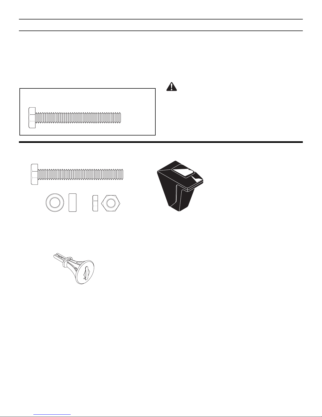
HOW TO MEASURE SCREW SIZE
DIAMETER
LENGTH
ASSEMBLY
9
PARTS BAGS CONTENTS:
* Non Assembly parts are found in toolbox located on top of belt cover.
*2 – Shear Bolt
*2 – Spacer
1 – Ignition Key
1 – Shift Lever Knob
(not actual size)
*2 – Nut
Page 10
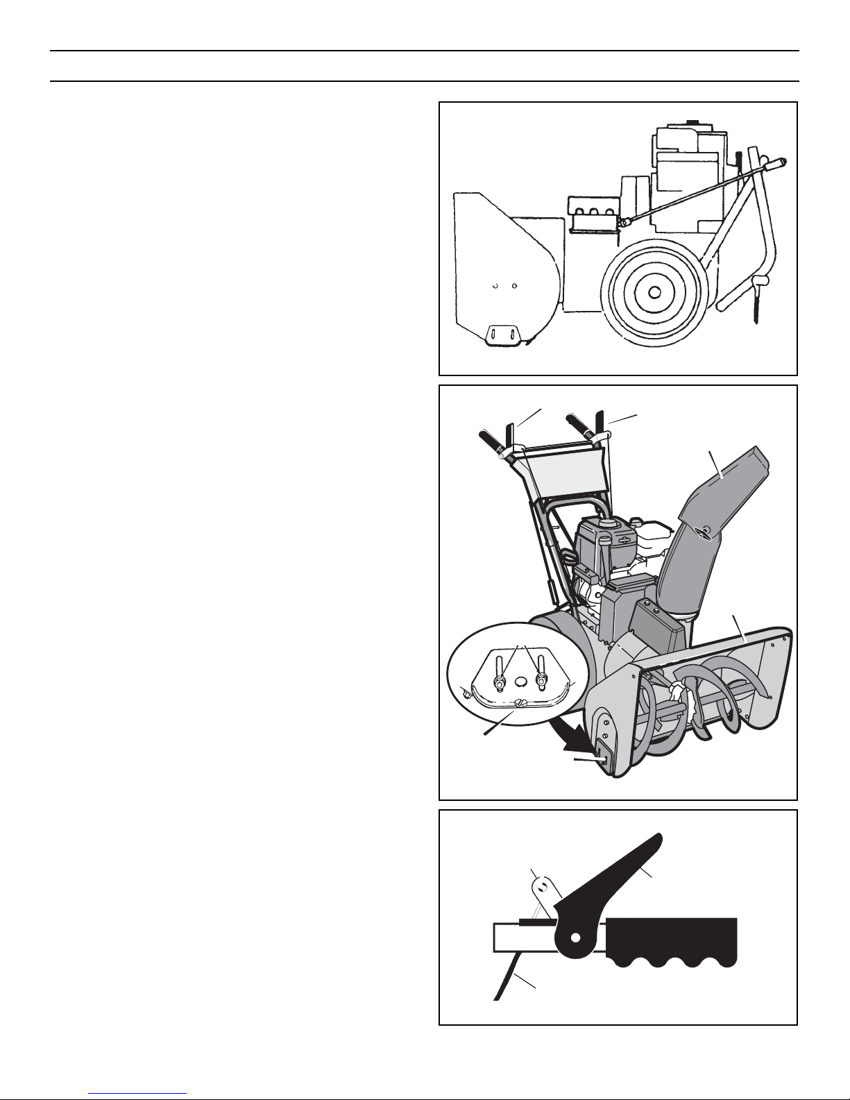
Figure 2 shows the snowthrower in the shipping position.
Figure 3 shows the snowthrower completely assembled.
Reference to right and left hand side of the snowthrower is from
the operator’s position at the handle.
UNPACKING
1. Locate the two tear tabs at the bottom of the carton.
2. Pull the tear tape no more than twelve inches (30.48 cm) at a
time. Regrasp tape next to the carton and pull again. Repeat
until all the tape is torn off.
3. After the tape has been completely removed from the carton,
remove the carton from the base. Cut all four corners and fold
the sides toward the center for easy disposal.
4. Remove the plastic bag that covers the unit.
5. Locate and remove the parts bag.
NOTE: Set the fuel stabilizer aside until adding gasoline to
the fuel tank. We recommend that fuel stabilizer is added to
the fuel each time that gasoline is added to the fuel tank.
6. For shipping purposes, the height adjust skids are attached to
the pallet. Remove the screw that secures each height adjust
skid to the pallet (see Figure 3).
7. Roll the snowthrower off the carton by pulling on the lower
handle.
CAUTION: DO NOT back over cables.
8. Remove the packing material from the handle assembly.
9. Cut ties securing the clutch control cables to the lower handle.
Figure 4
“Z” Fitting
Driver Lever
Cable
Figure 3
Auger Drive Lever
Snow Chute Deflector
Auger Housing
Height Adjust
Skid
Screw
Traction Drive Lever
Figure 2
ASSEMBLY
10
Page 11
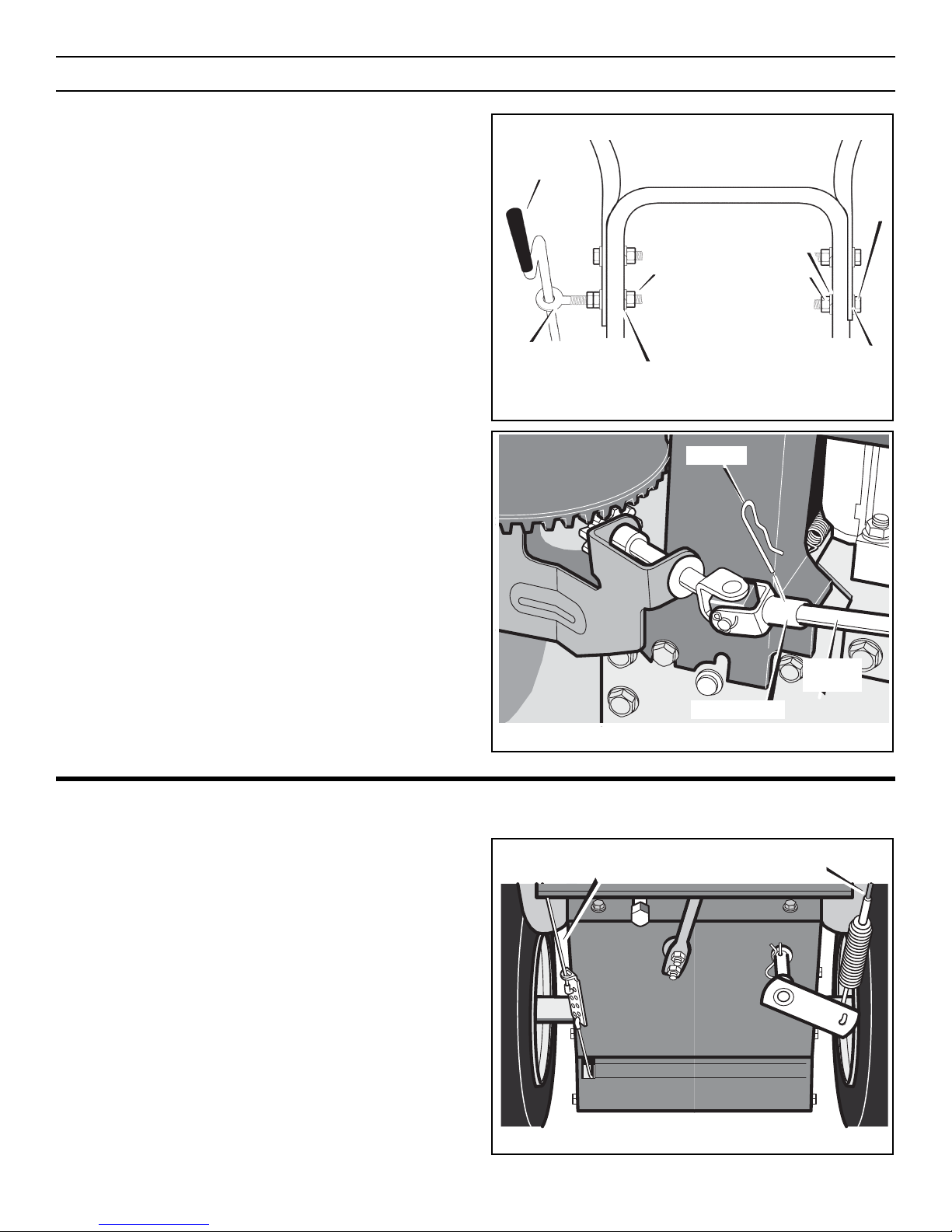
UPPER HANDLE AND CRANK ASSEMBLY
1. Loosen, but do not remove the screws, flatwashers, lockwashers and hex nuts in the upper holes of the lower handle.
2. Remove the fasteners and the crank assembly eyebolt from
the lower holes of the lower handle.
3. Raise upper handle into operating position. Upper handle
should be to the outside of the lower handle.
NOTE: Make sure the cables are not caught between the
upper and lower handle.
4. Install the fasteners and the crank assembly eyebolt that were
removed in step 2. DO NOT tighten until all fasteners are in
place.
5. Attach the crank rod to the universal joint assembly with the
hair pin (see Figure 6).
6. Tighten nut on eye bolt. Make sure eye bolt is properly aligned
and the crank can freely rotate.
7. Tighten all handle bolts.
NOTE: Make sure crank does not touch carburetor cover.
CHECK THE CABLES
1. If control cables have become unattached from motor mount
frame, reconnect cables as shown in Figure 7.
2. For cable adjustments, see “How To Check And Adjust The
Cables” in the MAINTENANCE section.
HOW TO SET THE LENGTH OF THE CABLES
The cables were adjusted at the factory and no adjustments should
be necessary. However, after the handles are put in the operating
position, the cables can be too tight or too loose. If an adjustment
is necessary, see “How To Check And Adjust The Cables” in the
MAINTENANCE section.
Figure 7
Traction Drive Cable
Auger Drive Cable
Hair Pin
Universal Joint
Crank Rod
Assembly
Figure 6
Figure 5
Crank
Bolt
Eye Bolt
Locknut
Flatwasher
Flatwasher
Lockwasher
Nut
ASSEMBLY
11
Page 12
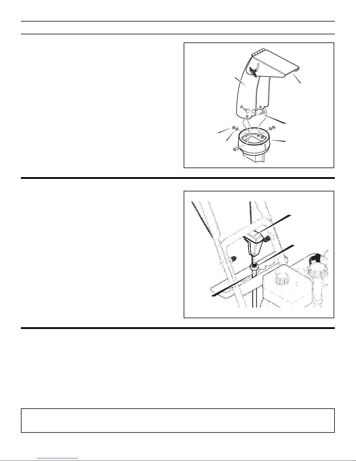
SNOW CHUTE ASSEMBLY
1. Position the snow chute to the INSIDE of the snow chute
flange. Align the three holes in the snow chute with holes in
snow chute flange (see Figure 8).
2. Place three 5/16–18 carriage bolts from inside of chute as
shown in Figure 8 (hardware is found in parts bag).
3. Place three 5/16–18 flatwashers and three 5/16–18 nuts on
outside of flange.
4. First, tighten the rear carriage bolt. Then, tighten the remaining two carriage bolts. Make sure all carriage bolts are tight.
NOTE: DO NOT over tighten carriage bolts.
SHIFTER LEVER KNOB ASSEMBLY
1. Thread the shifter knob onto the threaded end of the shifter
lever until it is snug against the hex nut and the lip is pointed
away from the engine (see Figure 9). On some models, the
shifter knob is attached.
2. Tighten hex nut against the bottom of the shifter lever knob.
CHECK THE TIRES
The tires were over inflated for shipment. Check the air pressure in
the tires. See the sidewall of the tire for the proper inflation.
IMPORTANT! BEFORE YOU START OPERATING
■■ Check the fasteners. Make sure all fasteners are tight.
■■ On electric start models, the unit was shipped with the starter
cord plugged into the engine. Before operating, unplug the
starter cord from the engine.
Figure 9
Shifter Knob
Hex Nut
Shifter Lever
Figure 8
Chute Extension
Carriage Bolts
Flange
Nut
Flatwasher
Snow Chute Deflector
ASSEMBLY
12
NOTE: This snowthrower was shipped WITH OIL in the engine. See “Before Starting Engine” instructions in the Operation section
of this manual before starting engine.
Page 13
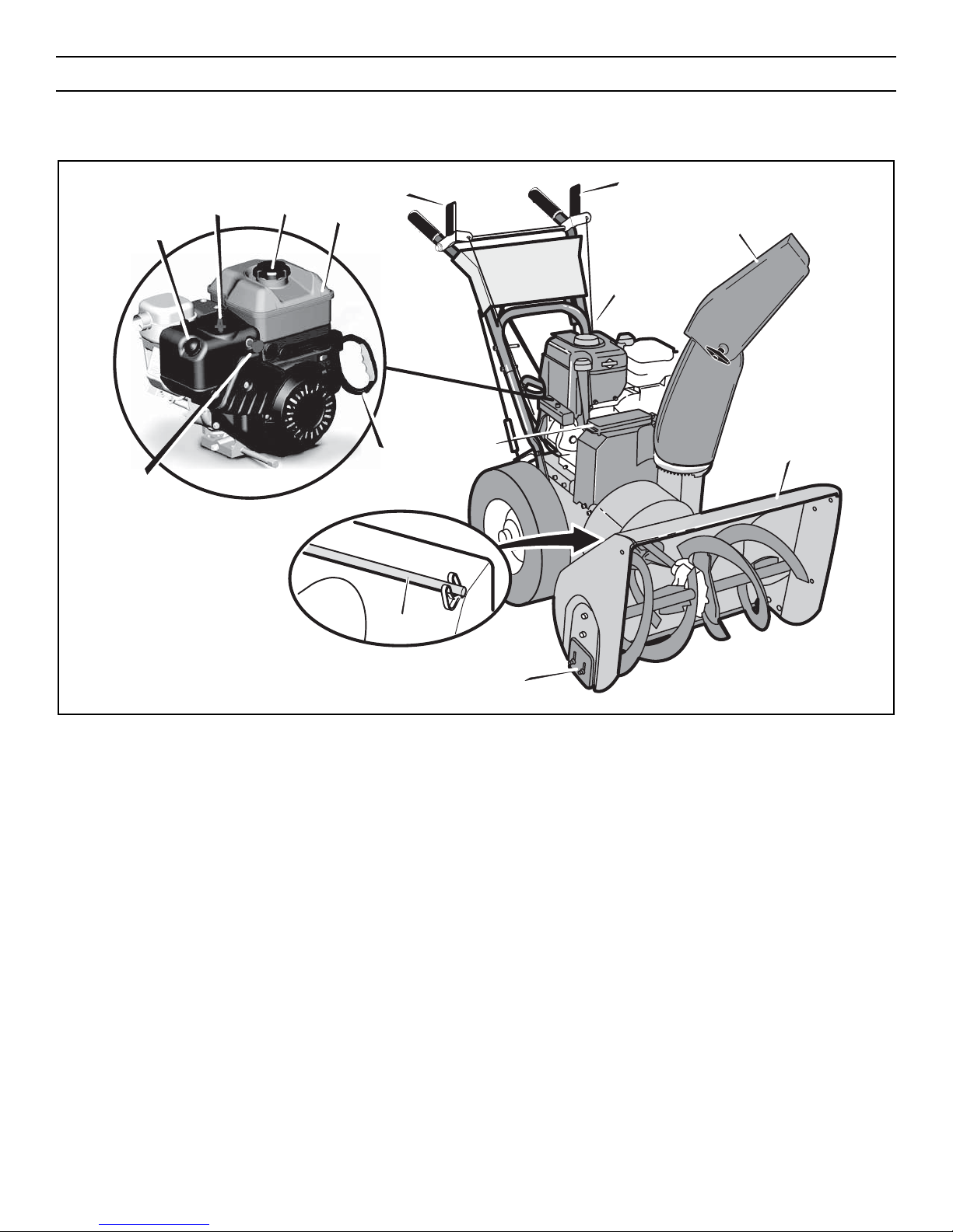
READ THIS OPERATOR’S MANUAL AND SAFETY RULES BEFORE OPERATING YOUR SNOWTHROWER. Compare the illustrations with
your SNOWTHROWER to familiarize yourself with the location of various controls and adjustments. Save this manual for future reference.
ENGINE AND SNOWTHROWER CONTROLS
Figure 10
Traction Drive Clutch Lever
Snow Chute Deflector
Auger Housing
Crank
Primer Button
Recoil
Starter
Handle
Toolbox
Clean-Out Tool
Height Adjust
Skid
Safety Key
Choke Control Gas Cap
Gas Tank
Auger Driver Clutch Lever
ENGINE CONTROLS
Choke Control – Used to start a cold engine.
Electric Start Button – Used to start the engine using the 120 volt
electric starter.
Primer Button – Used to inject fuel directly into carburetor manifold to insure fast starts in cool weather.
Safety Key – Must be inserted to start engine. Pull out to stop. Do
not turn safety key.
Starter Handle – Starts the engine manually.
SNOWTHROWER CONTROLS
Speed Select Lever – Allows the operator to use one of six (6) for-
ward and two (2) reverse speeds. To shift, move speed select lever
to desired position.
NOTE: Do not move speed select lever while Traction Drive
Clutch is engaged. This may result in severe damage to drive
system.
Auger Drive Clutch Lever – Used to engage and disengage the
auger and impeller. To engage push down, to disengage release.
Traction Drive Clutch Lever – Used to propel snowthrower forward or reverse. Push down to engage, release to disengage.
Snow Chute Deflector – Changes the direction the snow is thrown.
Crank – Used to change direction of the snow discharge. Turn han-
dle clockwise to turn chute to right. Turn handle counter clockwise
to turn chute to left.
Height Adjust Skid – Used to adjust ground clearance of auger
housing.
Toolbox – Spare shear bolts and spacers are located in toolbox.
Clean-Out Tool – Use the clean-out tool to remove snow and
debirs from the discharge chute and the auger housing.
Drift Cutters – Cuts a path through snow higher than the auger
housing.
OPERATION
13
Page 14
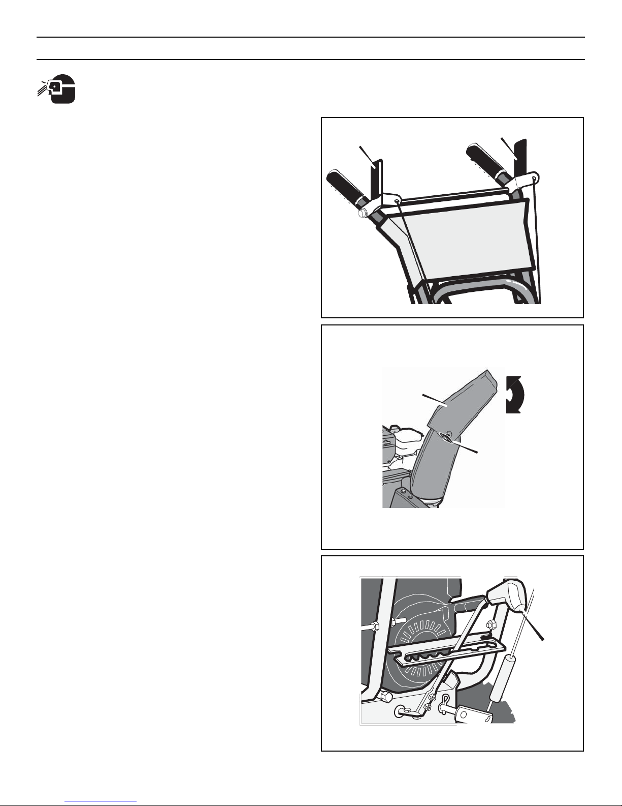
The operation of any snowthrower can result in foreign objects being thrown into the eyes, which can result in severe
eye damage. Always wear safety glasses or eye shields before beginning snowthrower Operation. We recommend
standard safety glasses or Wide Vision Safety Mask for over spectacles.
SNOWTHROWER OPERATION
The most effective use of the snowthrower will be established by
experience, taking into consideration the terrain, wind conditions
and building location which will determine the direction of the discharge chute.
NOTE: Do not throw snow toward a building as hidden objects
could be thrown with sufficient force to cause damage.
TO STOP YOUR SNOWTHROWER
1. To stop throwing snow, release the auger drive lever (see
Figure 11).
2. To stop the wheels, release the traction drive lever.
3. To stop the engine, push the throttle control lever to off and
pull out the ignition key.
TO CONTROL SNOW DISCHARGE
1. Rotate the crank to set the direction (left to right) of the discharge chute (see Figure 10).
2. Adjust the snow chute deflector. Loosen the wing nut on the
side of the snow chute deflector. Raise the snow chute
deflector for more distance or lower for less distance. Tighten
wing nut (see Figure 12).
HOW TO MOVE FORWARD AND BACKWARD
1. Start the engine. See “To Start Engine” in this section.
NOTE: Always release the traction drive lever before moving
the speed select lever.
2. Ground speed is determined by snow conditions. Set the
speed select lever (see Figure 13) in one of the following
positions.
1–2 Wet, Heavy, Slushy, Extra Deep
3 Moderate
4–5 Very Light
6 Transport Only
IMPORTANT: Before operating, make sure the area in front of
snowthrower is clear of bystanders or obstacles.
3. Engage the traction drive lever (see Figure 11). As the
snowthrower starts to move, maintain a firm hold on the handles and guide the snowthrower along the cutting path. Do not
attempt to push the snowthrower.
4. To stop forward motion, release the traction drive lever.
5. To move the snowthrower backwards, move the speed select
lever into either first or second reverse position and engage
the traction drive lever.
Figure 13
Speed Select
Lever
Figure 12
Chute Deflector
Wing Nuts
Figure 11
Auger Drive Lever
Traction Drive Lever
OPERATION
14
Page 15
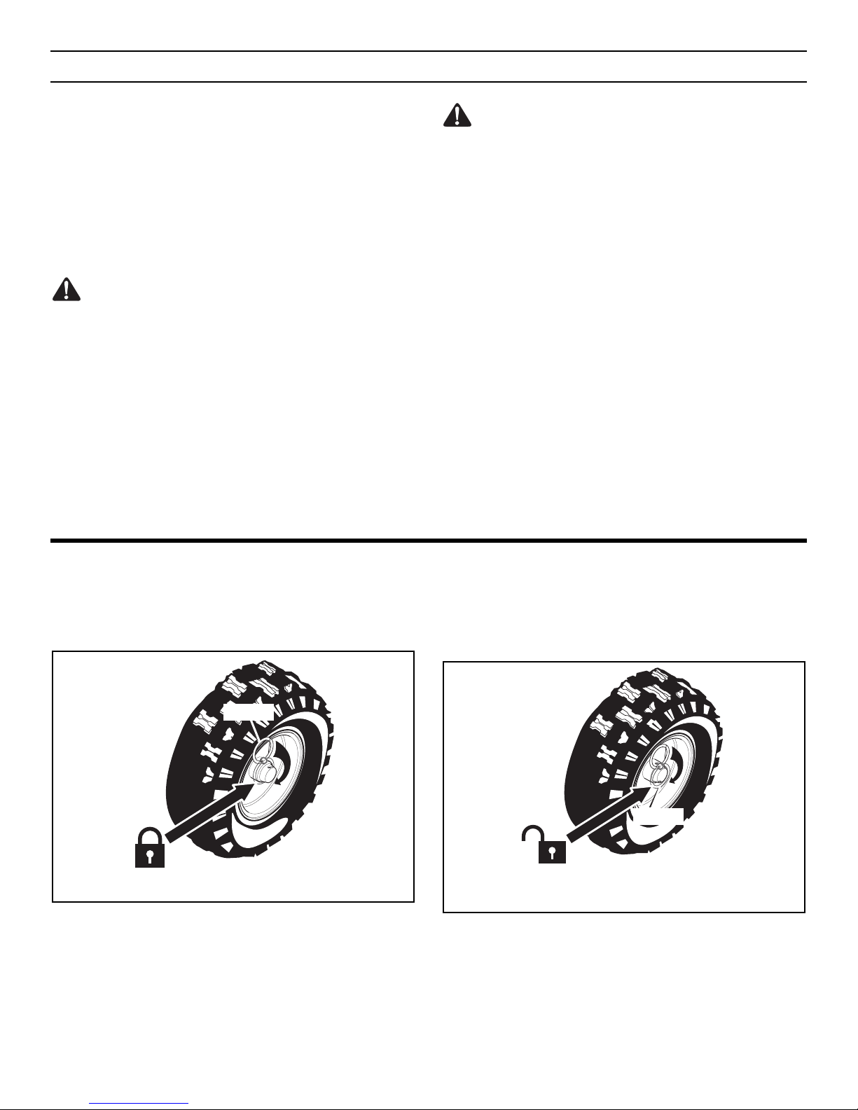
WHEEL LOCK OUT PIN
1. The right wheel is secured to the axle with a klick pin. This unit
was shipped with this klick pin in the locked position
(Figure 14).
2. For ease of maneuverability when lighter conditions prevail,
remove klick pin from wheel locked position and insert into
single wheel drive (unlocked) position (Figure 15). Make sure
that the klick pin is in the single wheel drive position of the
axle only and not through the locked position.
NOTE: Check tire pressure. See side of tire for maximum inflation. Do not exceed listed maximum pressure.
Figure 15
Klick Pin
Single Wheel Drive
Position (Unlocked)
Figure 14
Klick Pin
Locked Position
TO THROW SNOW
1. Push down the auger driver lever (right hand). See Figure 11.
2. To stop throwing snow, release the auger drive lever.
NOTE: When clearing wet, heavy snow, it is recommended
that the ground speed of the unit be reduced, maintain full
throttle and do not attempt to clear the full width of the unit.
For additional operating instructions see “Operating Tips” in
this section.
WARNING: Read Operator’s Manual before operating
machine. This machine can be dangerous if used
carelessly.
Never operate the snowthrower without all guards, covers, and
shields in place.
Never direct discharge towards windows or allow bystanders
near machine while engine is running.
Stop the engine whenever leaving the operating position.
Disconnect spark plug before unclogging the impeller housing or
the discharge chute and before making repairs or adjustments.
When leaving the machine, remove the ignition key. To reduce
the risk of fire, keep the machine clean and free from spilled
gas, oil and debris.
WARNING: Never run engine indoors or in an enclosed,
poor ventilated area. Engine exhaust contains CARBON
MONOXIDE, an ORDERLESS and DEADLY GAS.
Keep hands, feet, hair and loose clothing away from any moving
parts on engine and snowthrower.
Temperature of muffler and nearby areas can exceed 150°F
(66°C). Avoid these areas.
DO NOT allow children or young teenagers to operate or be near
snowthrower while it is operating.
OPERATION
15
Page 16
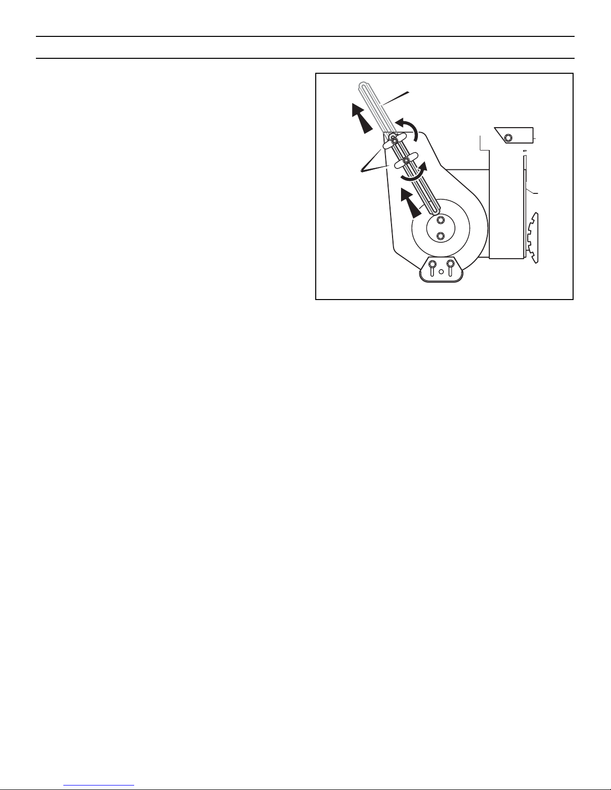
HOW TO SET THE DRIFT CUTTERS
(OPTIONAL ACCESSORY ON SOME MODELS)
Drift cutters are used to cut a path through snow deeper than the
auger housing.
1. Loosen the wingnuts that secure the drift cutters to the auger
housing (see Figure 16).
2. Raise the drift cutters to the desired height.
3. Tighten the wingnuts.
Figure 16
Drift Cutter
Wingnut
OPERATION
16
Page 17
BEFORE STARTING ENGINE
CHECK THE ENGINE
NOTE: The engine was shipped from the factory filled with oil.
Check the level of the oil. Add oil as needed.
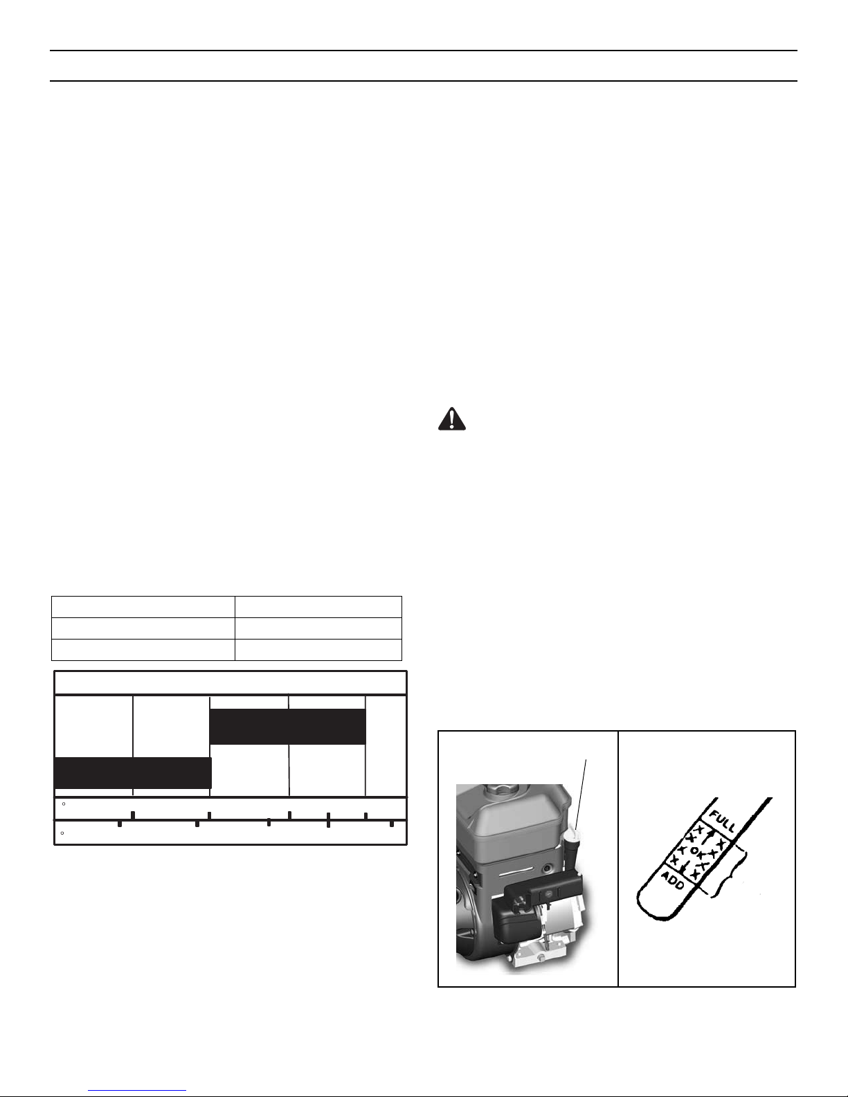
1. Make sure the unit is level. Use a high quality detergent oil
classified “For Service SG, SH, SJ, SL, or higher”.
2. Remove the oil fill cap/dipstick and wipe with a clean cloth
(see Figure 17).
3. Insert the oil fill cap/dipstick and turn clockwise to tighten.
4. Remove the oil fill cap/dipstick and check the oil.
NOTE: Do not check the level of the oil while the engine
runs.
5. If necessary, add oil until the oil reaches the FULL mark on the
oil fill cap/dipstick (see Figure 17). Do not add too much oil.
6. Tighten the fill cap/dipstick securely each time you check the
oil level.
NOTE: For extreme cold operating conditions of 0°F (-18°C) and
below, use a synthetic 5W30 motor oil for easier starting.
NOTE: S.A.E. 5W30 motor oil may be used to make starting easier in areas where the temperature is 20°F (-7°C) to 0°F (-18°C).
Synthetic 5W30 is acceptable for all temperatures. DO NOT mix
oil with gasoline.
NOTE: SEE CHART FOR OIL RECOMMENDATION.
FILL GAS
This engine is certified to operate on gasoline. Exhaust Emission
Control System: EM (Engine Modifications)
1. Fill the fuel tank with fresh, clean, unleaded regular, unleaded
premium, or reformulated automotive gasoline with a minimum of 85 octane along with a fuel stabilizer (follow instructions on fuel stabilizer package). DO NOT use leaded gasoline.
We recommend that fuel stabilizer be added to the fuel each
time that gasoline is added to the fuel tank.
NOTE: Winter grade gasoline has higher volatility to
improve starting. Be certain container is clean and free
from rust or other foreign particles. Never use gasoline that
may be stale from long periods of storage in the container.
CAUTION: DO NOT use gasoline containing any amount of
alcohol as it can cause serious damage to the engine or significantly reduce the performance.
WARNING: Gasoline is flammable. Always use caution
when handling or storing gasoline. Turn engine off and let
engine cool at least two minutes before removing the gas cap.
Do not add gasoline to the fuel tank while snowthrower is
running, hot, or when snowthrower is in an enclosed area. Keep
away from open flame, electrical sparks and DO NOT SMOKE
while filling the fuel tank. Never fill the fuel tank completely; but
fill the fuel tank to within 1-1/2 inches (3.8 mm) from the top to
provide space for the expansion of the fuel. Always fill fuel tank
outdoors and use a funnel or spout to prevent spilling. Make
sure to wipe up any spilled fuel before starting the engine.
Store gasoline in a clean, approved container, and keep the cap
in place on the container. Keep gasoline in a cool well ventilated
place; never in the house. Never buy more than a 30 day supply
of gasoline to assure volatility. Gasoline is intended to be used
as a fuel for internal combustion engines; therefore, do not use
gasoline for any other purpose. Since many children like the
smell of gasoline, keep it out of their reach because the fumes
are dangerous to inhale, as well as being explosive.
Figure 17
Oil Fill Cap/Dipstick
Safe
Synthetic 5W30
5W30
SAE VISCOSITY GRADES
TEMPERATURE TYPE OF OIL
0°F (-18°C) and above S.A.E. 5W30
0°F (-18°C) and below synthetic 5W30
OPERATION
17
F−
C −30 −20 −10 0 10
20
0203240
Page 18
BEFORE STOPPING THE ENGINE
Run the engine for a few minutes to help dry off any moisture on
the engine.
TO STOP ENGINE
CAUTION: To stop the engine, do not move the choke control to
CHOKE position. Backfire or engine damage can occur.
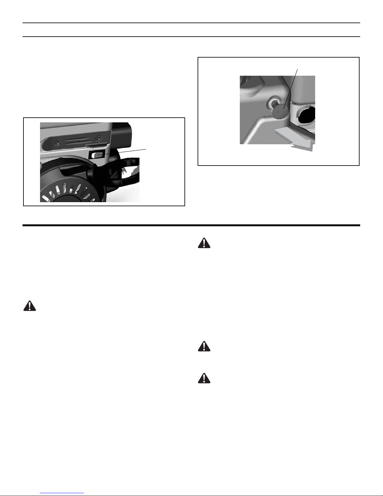
1. Push the stop switch to the OFF position.
2. Pull out the safety key.
Figure 19
Safety Key
Figure 18
Stop Switch
OPERATION
18
TO START ENGINE
Be sure that engine oil is at FULL mark on the oil fill cap/dipstick.
The snowthrower engine is equipped with a 120 volt AC electric
starter and recoil starter. Before starting the engine, be certain that
you have read the following information.
If engine floods, set the choke to the OPEN/RUN position and crank
until the engine starts.
WARNING: Rapid retraction of the starter cord (kickback)
will pull your hand or arm toward the engine faster than
you can let go of the starter cord.
• When starting the engine, slowly pull the starter cord until
resistance is felt. Then, rapidly pull the starter cord.
• Make sure components; such as impellors, pulleys or sprockets, are securely attached.
WARNING: The electric starter is equipped with a three-
wire power cord and plug designed to operate on 120 volt
AC household current. The power cord must be properly
grounded at all times to avoid the possibility of electric shock
which can cause injury to the operator. Follow all instructions
carefully as set forth below:
Make sure your house has a three-wire grounded system. If you
are not sure, ask a licensed electrician. If your house does not
have a three-wire grounded system, do not use this electric
starter under any condition.
If your house has a three-wire grounded system but a three-hole
receptacle is not available to connect the electric starter, have a
three-hole receptacle installed by a licensed electrician.
WARNING: To connect a 120 volt power cord, always
connect the power cord first to the switch box located on
the engine and then plug the other end into a three-hole
grounded receptacle.
WARNING: To disconnect the power cord, always unplug the
end connected to the three-hole grounded receptacle first.
Page 19
How To Start A Cold Engine
1. Be sure auger drive and traction drive levers are in the disen-
gaged (RELEASED) position.
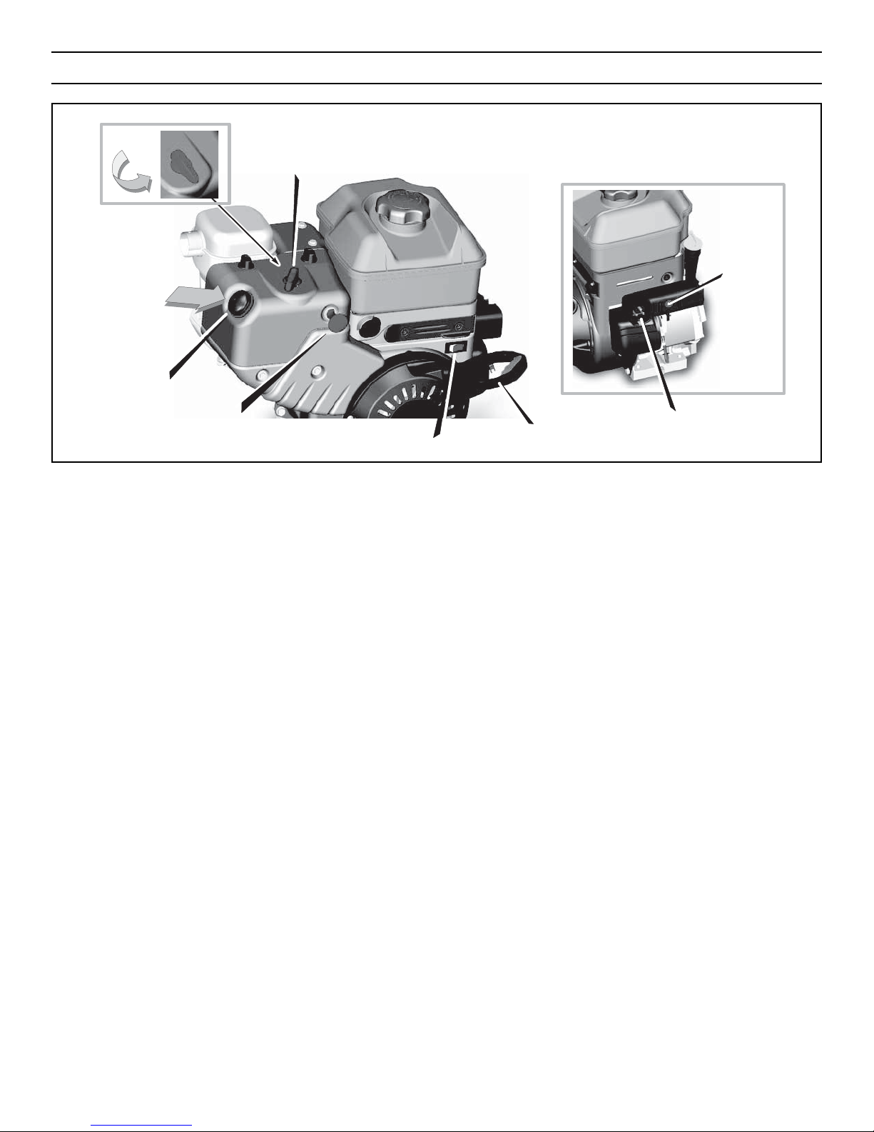
2. Push the stop switch to the ON position (see Figure 20).
3. Push in the safety key.
4. Rotate the choke knob to the CHOKE position.
5. (Electric Start) Plug the power cord into the starter motor on
the engine. Plug the other end of power cord into a three-hole,
grounded 120 volt, AC receptacle.
6. Push the primer button as specified below. Remove finger
from primer button between pushes.
• Push two times if temperature is 15° F (-9° C) or higher.
• Push four times if temperature is below 15° F (-9° C).
7. (Electric Start) Connect the power cord to the engine and
depress the starter button. To prolong the life of the starter, do
not crank for more than 5 seconds at a time. Wait one minute
between starts to allow the starter motor to cool.
8. (Recoil Start) Slowly pull the recoil starter handle until
resistance is felt and then pull rapidly to start the engine. Do
not allow the recoil starter handle to snap back. Slowly return
the recoil starter handle.
9. If the engine does not start in 5 or 6 tries, see Difficult Starting
in the TROUBLE SHOOTING CHART.
10. Allow the engine to warm up for several minutes. As the
engine warms up, adjust the choke knob toward the RUN
position. Wait until the engine runs smoothly before each
choke adjustment.
11. (Electric Start) First disconnect power cord from receptacle.
Then, disconnect the power cord from the switch box.
If after following the preceding instructions, your engine fails to
start, have the engine checked by a John Deere/Frontier dealer.
NOTE: Do not lose the safety/ignition key. Keep the safety/ignition key in a safe place. The engine will not start without the
safety/ignition key.
How To Start A Warm Engine
If restarting a warm engine after a short shutdown, leave the choke
lever in the off position and do not push the primer button. If the
engine fails to start, follow the Cold Start instructions.
OPERATION
19
Figure 20
Primer
Recoil Starter Handle
Safety Key
Stop Switch
Starter Motor
Starter
Button
Choke Knob
Page 20
FROZEN STARTER
If the starter is frozen and will not turn engine:
1. Pull as much rope out of the starter as possible.
2. Release the starter handle and let it snap back against the
starter. Repeat until the engine starts.
Warm engines will cause condensation in cold weather. To help
prevent possible freeze-up of recoil starter and engine controls,
proceed as follows after each snow removal job.
1. With engine off, allow engine to cool for several minutes.
2. Pull starter rope very slowly until resistance is felt, then stop.
Allow the starter rope to recoil. Repeat three times.
3. With the engine not running, wipe all snow and moisture from
the carburetor cover in area of control levers. Also move
choke knob and starter handle several times.
WARNING: Never run engine indoors or in enclosed,
poorly ventilated areas. Engine exhaust contains CARBON
MONOXIDE, AN ODORLESS AND DEADLY GAS. Keep hands,
feet, hair and loose clothing away from any moving parts on
engine and snowthrower.
• Engine parts, especially the muffler, become extremely hot.
Severe thermal burns can occur on contact. Allow the engine
to cool before touching.
• Never allow children to operate the snowthrower. Never allow
adults to operate the snowthrower without proper instruction.
• Keep the area of operation clear of all persons, particularly
small children, and pets.
• Never leave the snowthrower unattended while the engine is
running. Anyone operating the engine or equipment must
carefully read and understand the operating instructions.
IMPORTANT: After each use of the snowthrower, stop the engine,
remove the safety/ignition key, remove all accumulated snow
from the snowthrower and wipe clean. Store the snowthrower in
a protected area.
NOTE: Never cover snowthrower while engine and exhaust area
are still warm.
OPERATION
20
HOW TO CLEAR A CLOGGED DISCHARGE CHUTE
WARNING: Hand contact with the rotating impeller inside
the discharge chute is the most common cause of injury
associated with snowthrowers. NEVER USE YOUR HAND TO
CLEAN OUT THE DISCHARGE CHUTE.
To Clear The Chute:
• SHUT OFF THE ENGINE!
• Wait 10 seconds to be sure that the impeller blades have
stopped rotating.
• Always use a clean-out tool, not your hands.
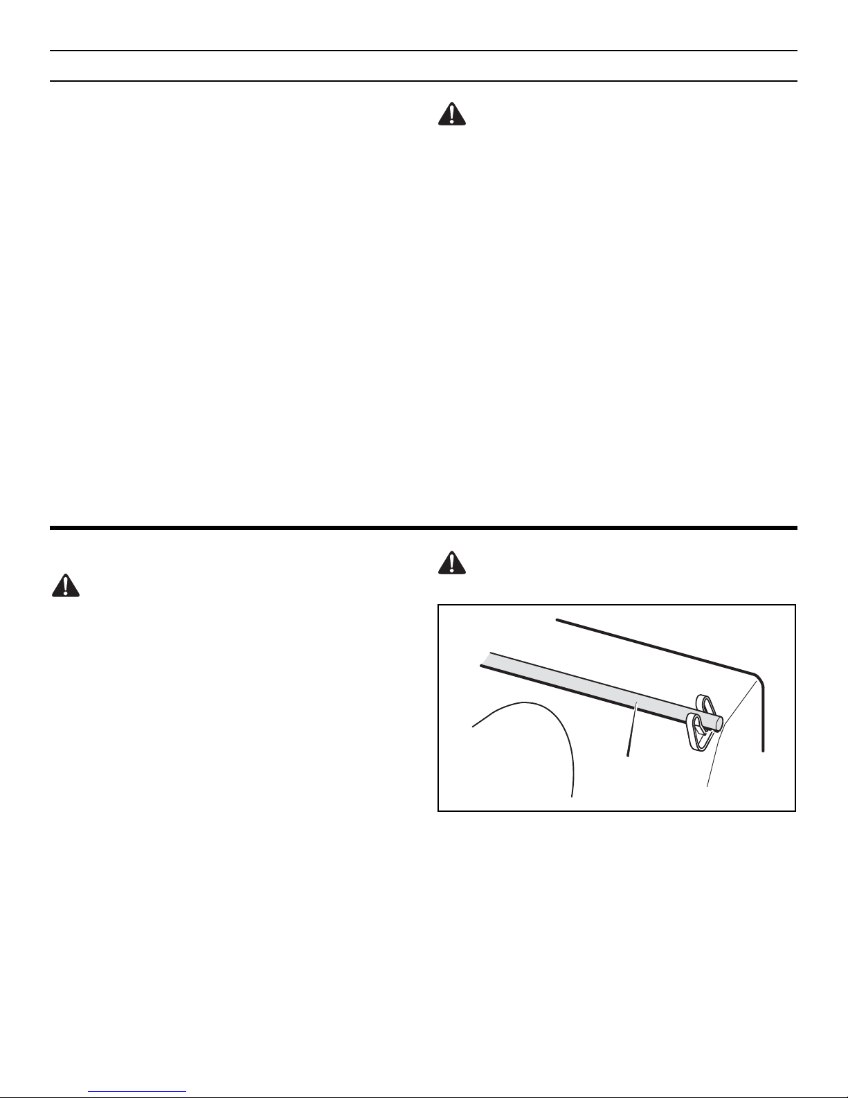
A clean-out tool is attached to either the handle or the top of the
auger housing (see Figure 21). Use the clean-out tool to remove
snow from the auger housing.
HOW TO USE CLEAN-OUT TOOL
• Release the auger drive lever.
• Pull out the safety key.
• Disconnect spark plug wire.
• Do not place your hands in the auger or discharge chute. Use a
clean-out tool to remove snow or debris.
WARNING: Blockage must be cleared only after shutting
off the snowthrower and only with a clean-out tool, not by
hand.
Figure 21
Clean-Out Tool
Page 21

OPERATING TIPS
1. Most efficient snowthrowing is accomplished when snow is
removed immediately after it falls.
2. For complete snow removal, slightly overlap each swath previously taken.
3. Snow should be discharged downwind whenever possible.
4. For normal usage, set the skids 1/8 inch (3 mm) below the
scraper bar. For extremely hard-packed snow surfaces, the
skids may be adjusted upward to insure cleaning efficiency.
5. On gravel or crushed rock surfaces, the skids should be set at
1-1/4 inch (32 mm) below the scraper bar (see “To Adjust
Skid Height”, in the MAINTENANCE section in this manual).
Rocks and gravel must not be picked up and thrown by the
machine.
6. After the snowthrowing job has been completed, allow the
engine to idle for a few minutes, to melt snow and ice accumulated on the engine.
7. Clean the snowthrower thoroughly after each use.
8. Remove ice and snow accumulation and all debris from the
entire snowthrower, and flush with water (if possible) to
remove all salt or other chemicals. Wipe snowthrower dry.
9. Before starting snowthrower, always inspect augers and
impeller for ice accumulation and/or debris, which could
result in snowthrower damage.
10. Check oil level before every start. Make sure the oil is at the
FULL mark on the oil fill cap/dipstick.
OPERATION
21
Page 22

The warranty on this snowthrower does not cover items that have
been subjected to operator abuse or negligence. To receive full
value from the warranty, operator must maintain snowthrower as
instructed in this manual. The above Service Recommendations
are supplied to assist operator to properly maintain snowthrower.
This is a check list only. Adjustment referred to will be found in the
MAINTENANCE section of this manual.
AFTER EACH USE
1. Check for any loose or damaged parts.
2. Tighten any loose fasteners.
3. Check and maintain the auger.
4. After each use, remove all snow and slush off the snowthrower to prevent freezing of auger or controls.
5. Check controls to make sure they are functioning properly.
6. If any parts are worn or damaged, replace immediately.
SERVICE RECOMMENDATIONS
22
SERVICE RECOMMENDATIONS
PROCEDURE
FIRST
2
HOURS
BEFORE
EACH
USE
OFTEN
EVERY
5
HOURS
EVERY
10
HOURS
EVERY
25
HOURS
BEGINNING
EACH
SEASON
BEFORE
STORAGE
SNOWTHROWER
Tighten all screws
and nuts
✓ ✓ ✓
Check Traction
Clutch Cable
Adjustment (See
Cable Adjustment)
✓ ✓
Check Auger Clutch
Cable Adjustment
(See Cable
Adjustment)
✓ ✓ ✓
Lubricate Chains
and Hex Shaft
✓
ENGINE
Oil, Check
✓ ✓ ✓
Oil, Change
✓ ✓ ✓
Page 23
Some adjustments will need to be made periodically to properly
maintain your snowthrower.
All adjustments in this section of this manual should be checked at
least once each season.
SNOWTHROWER
Auger and Traction Drive Belts should be adjusted after the first 2
to 4 hours of use, again about midseason and twice each season
thereafter (see “To Adjust Belts” paragraph in this section).
AS REQUIRED
Auger Gear Box
The auger gear box is lubricated at the factory and should not
require additional lubrication.
If for some reason the lubricant should leak out, or if the auger
gear box has been serviced, add Lubriplate GR132 Grease or
equivalent. Maximum 3-1/4 ounces, (92 grams) should be used.
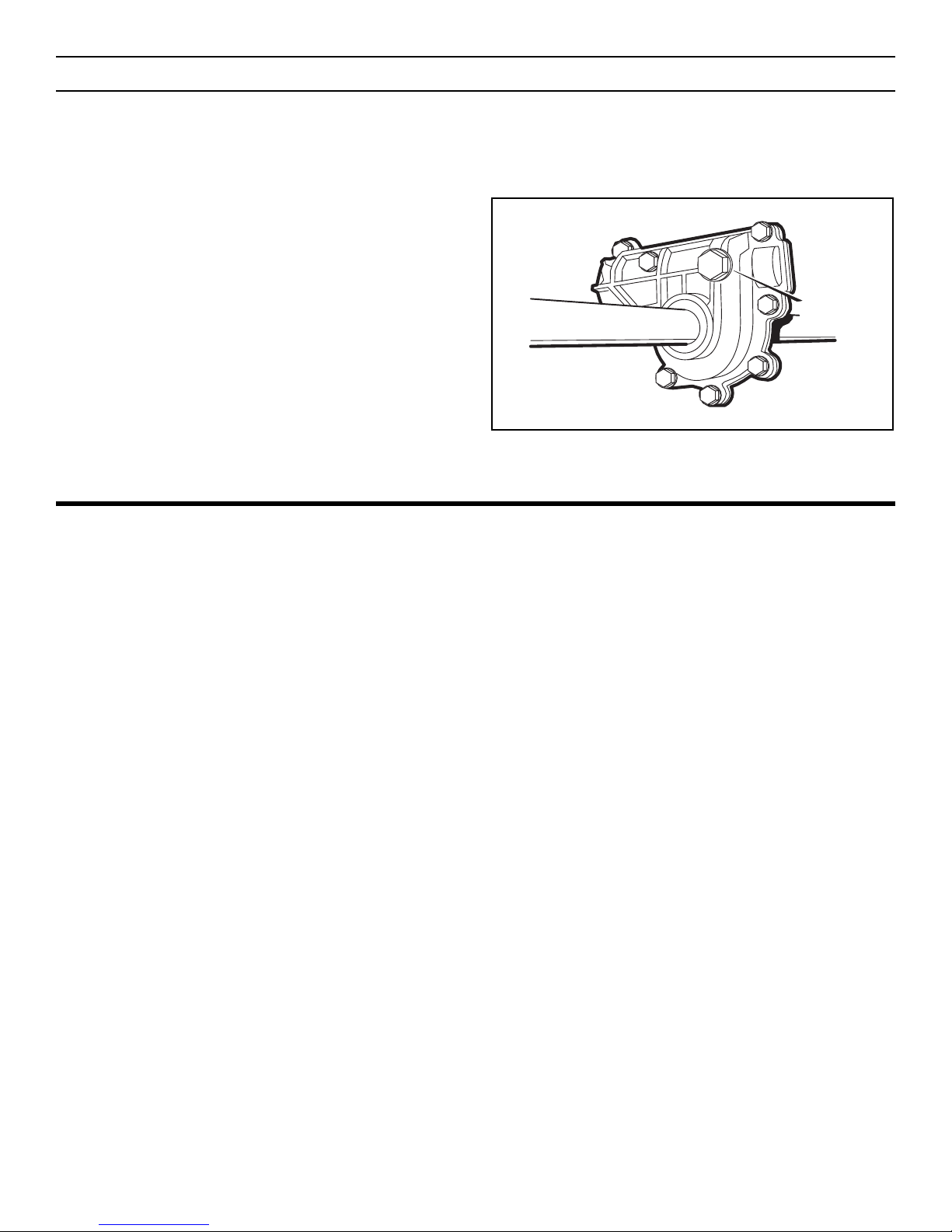
Remove filler plug (Figure 22), once a year. If grease is visible, do
not add. If grease is not visible, use a piece of fine wire, like a dipstick to check if there is grease in the gear box. Mobilux EP1 and
Shell Aldania EP1 are suitable equivalents.
Figure 22
Filler Plug
MAINTENANCE
23
LUBRICATION AT STORAGE
Bearings and Bushings
All bearings and bushings are lifetime lubricated and require no
maintenance.
Hex Shaft and Chains
For storage, the hex shaft should be wiped with a cloth lightly
moistened with motor oil to prevent rusting (see Figure 24).
For storage, the chains should be lubricated with a chain type lube
(see Figure 24).
NOTE: Any greasing or oiling of the above mentioned components can cause contamination of the rubber friction wheel. If
the disc drive plate or friction wheel come in contact with grease
or oil damage to rubber friction wheel will result.
If grease or oil comes into contact with the disc drive plate or friction wheel, make sure to clean plate and wheel thoroughly with an
alcohol base solvent.
Page 24
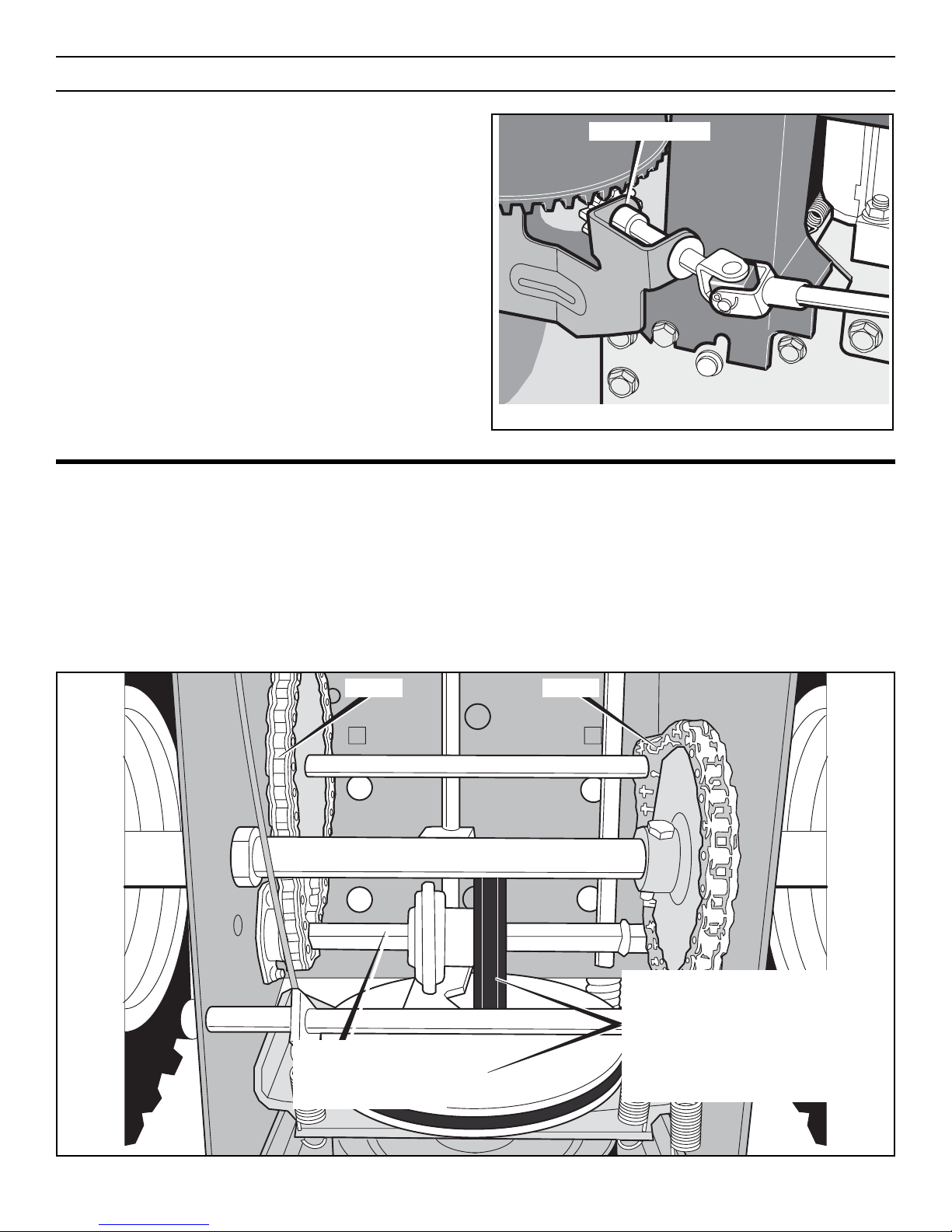
LUBRICATION – EVERY 25 HOURS
Chute Rotation Gear
Lubricate the chute rotation gear with automotive type oil (see
Figure 23).
Figure 23
Chute Rotation Gear
Chains
1. Position speed selector lever in first (1) forward gear.
2. Stand the snowthrower up on the auger housing end.
NOTE: When the crank case if filled with oil, do not leave
the snowthrower standing up on the auger housing for an
extended period of time.
3. Remove the bottom panel.
4. Lubricate the chains with a chain type lubricant.
5. Wipe the hexshaft and sprockets with 5W30 motor oil.
NOTE: Clean all excess grease or oil found on the rubber
friction wheel or the disc drive plate.
CAUTION: Do not allow grease or oil to contact the rubber
friction wheel or the disc drive plate.
6. Install the bottom panel.
MAINTENANCE
24
Figure 24
Chain
Hexshaft – wipe with
5W30 motor oil before
storage and at the
beginning of each season
WARNING: If the disc drive plate or rubber
friction wheel come in contact with grease or
oil damage to rubber friction wheel will
result.
If grease or oil come in contact with the disc
drive plate or friction wheel, make sure to clean
the plate and wheel thoroughly with an alcohol
base solvent.
Chain
Page 25
ENGINE
POWER RATINGS
The power ratings for an individual engine model are initially developed by starting with SAE (Society of Automotive Engineers) code
J1940 (Small Engine Power & Torque Rating Procedure) (Revision
2002-05). Given both the wide array of products on which our
engines are placed, and the variety of environmental issues applicable to operating the equipment, it may be that the engine you
have purchased will not develop the rated horsepower when used
in a piece of power equipment (actual “on-site” power). This difference is due to a variety of factors including, but not limited to, the
following: differences in altitude, temperature, barometric pressure, humidity, fuel, engine lubrication, maximum governed engine
speed, individual engine to engine variability, design of the particular piece of power equipment, the manner in which the engine is
operated, engine run-in to reduce friction and clean out of combustion chambers, adjustments to the valves and carburetor, and other
factors. The power ratings may also be adjusted based on comparisons to other similar engines utilized in similar applications, and
will therefore not necessarily match the values derived using the
foregoing codes.
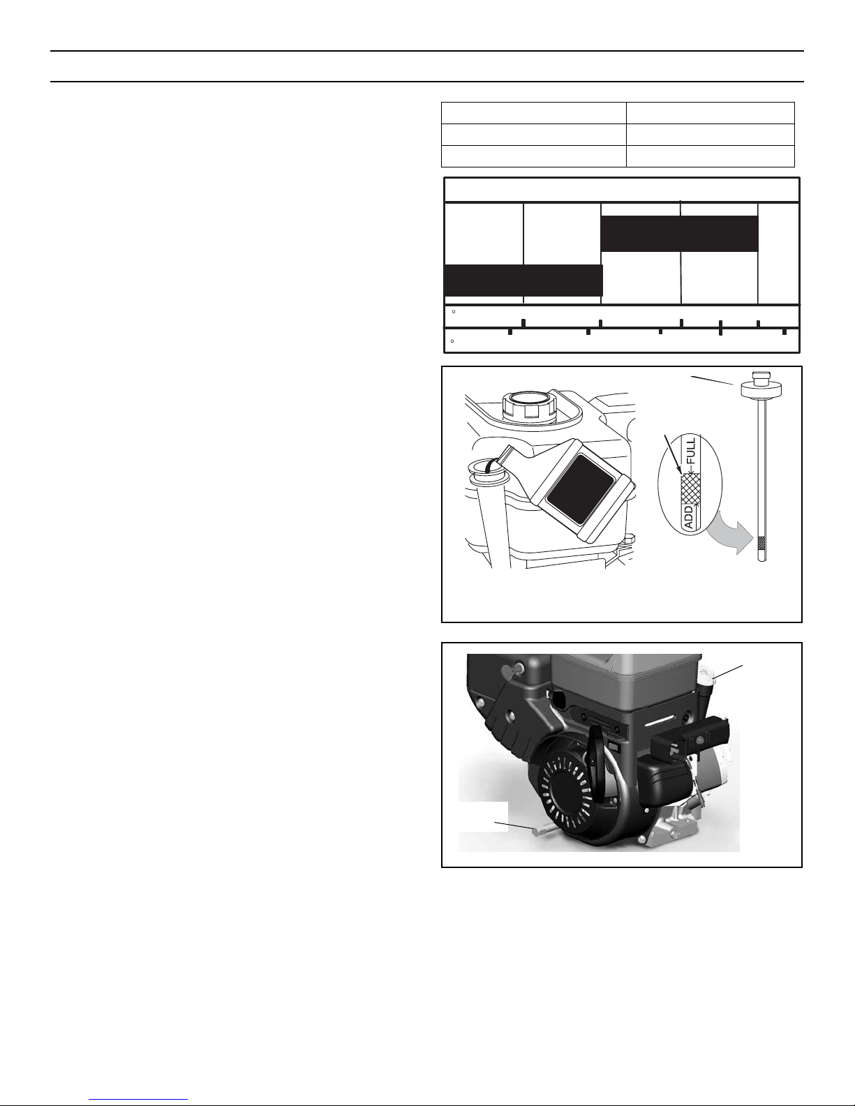
Check Crankcase Oil Level before starting engine and after each 8
hours of continuous use (see Figure 25). Add the recommended
motor oil as required.
NOTE: Overfilling the engine can affect performance. Tighten the
oil fill cap securely to prevent leakage.
Change Oil every 50 hours of operation or at least once a year,
even if the snowthrower is not used for fifty hours. Use a clean,
high quality detergent oil. Fill the crank case to FULL line on dipstick (see Figure 25). Be sure original container is marked: A.P.I.
service “SF” or higher. Do not use SAE10W40 oil (as it may not
provide proper lubrication). See Chart for oil recommendations.
To Drain Oil – Position snowthrower so that the oil drain plug is lowest point on engine. When the engine is warm, remove oil drain plug
and oil fill cap and drain oil into a suitable container (Figure 26).
Replace oil drain plug and tighten securely. Refill crank case with
the recommended motor oil.
Figure 26
Oil Fill Cap/
Dipstick
Oil Drain
Plug
Figure 25
Oil Fill Cap/Dipstick
Full
NOTE: Oil level must be at FULL mark.
Synthetic 5W30
5W30
SAE VISCOSITY GRADES
TEMPERATURE TYPE OF OIL
0°F (-18°C) and above S.A.E. 5W30
0°F (-18°C) and below synthetic 5W30
MAINTENANCE
25
F−
C −30 −20 −10 0 10
20
0203240
Page 26
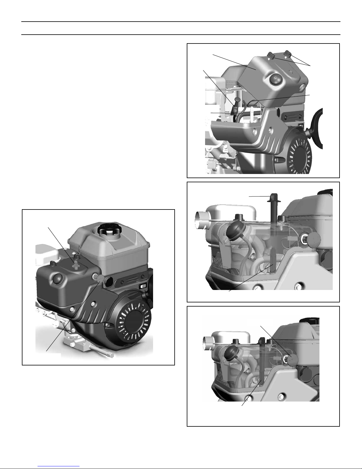
HOW TO REMOVE THE SNOW HOOD
To access the spark plug, the snow hood must be removed as
follows:
1. Remove the choke control knob (see Figure 27).
2. Remove the safety key.
3. Remove the mounting screws (see Figure 28).
4. Slowly remove the snow hood. Make sure that the primer but-
ton hose and the ignition wire are not disconnected.
5. The spark plug can now be accessed.
6. To install the snow hood, first make sure that the primer button hose and the ignition wire are connected.
7. Mount the snow hood to the engine and secure with the
mounting screws (see Figure 28).
8. Connect the choke control knob with the choke shaft on the
carburetor (see Figure 29 and Figure 30). Make sure the choke
control knob is properly installed. If the choke control knob is
not installed correctly, the choke will not operate.
9. Install the safety key.
Figure 30
Safety Key
Carburetor
Figure 29
Choke Control Knob
Choke Shaft
Figure 28
Mounting
Screws
Ignition
Wire
Primer Button
Hose
Snow Hood
Spark Plug
Figure 27
Choke Control Knob
Safety Key
MAINTENANCE
26
Page 27
WARNING: Always turn unit off, remove ignition key and
disconnect the spark plug wire before making any repairs
or adjustments.
AUGER HOUSING HEIGHT ADJUSTMENT
TO ADJUST SCRAPER BAR
After considerable use, the metal scraper bar will have a definite
wear pattern. The scraper bar in conjunction with the skids should
always be adjusted to allow 1/8 inch (3 mm) between the scraper
bar and the sidewalk or area to be cleaned.
To adjust the scraper bar, proceed as follows:
1. Position the snowthrower on a level surface.
2. Loosen the carriage bolts and nuts securing the scraper bar to
the auger housing.
3. Adjust the scraper bar to the proper position. Tighten the carriage bolts and nuts, insuring that the scraper bar is parallel
with the working surface.
4. For extended operation, the scraper bar may be reversed. If
the scraper bar must be replaced because of wear, remove the
carriage bolts and nuts and install a new scraper bar.
TO ADJUST SKID HEIGHT
This snowthrower is equipped with two height adjust skids,
secured to the outside of the auger housing. These elevate the
front of the snowthrower.
When removing snow from a hard surface area such as a paved
driveway or walk, adjust the skids up to bring the front of the
snowthrower down.
When removing snow from rock or uneven construction, raise the
front of the snowthrower by moving the skids down. This will help
to prevent rocks and other debris from being picked up and thrown
by the augers.
To adjust skids, proceed as follows:
1. Place a block (equal to height from ground desired) under
scraper bar near but not under skid.
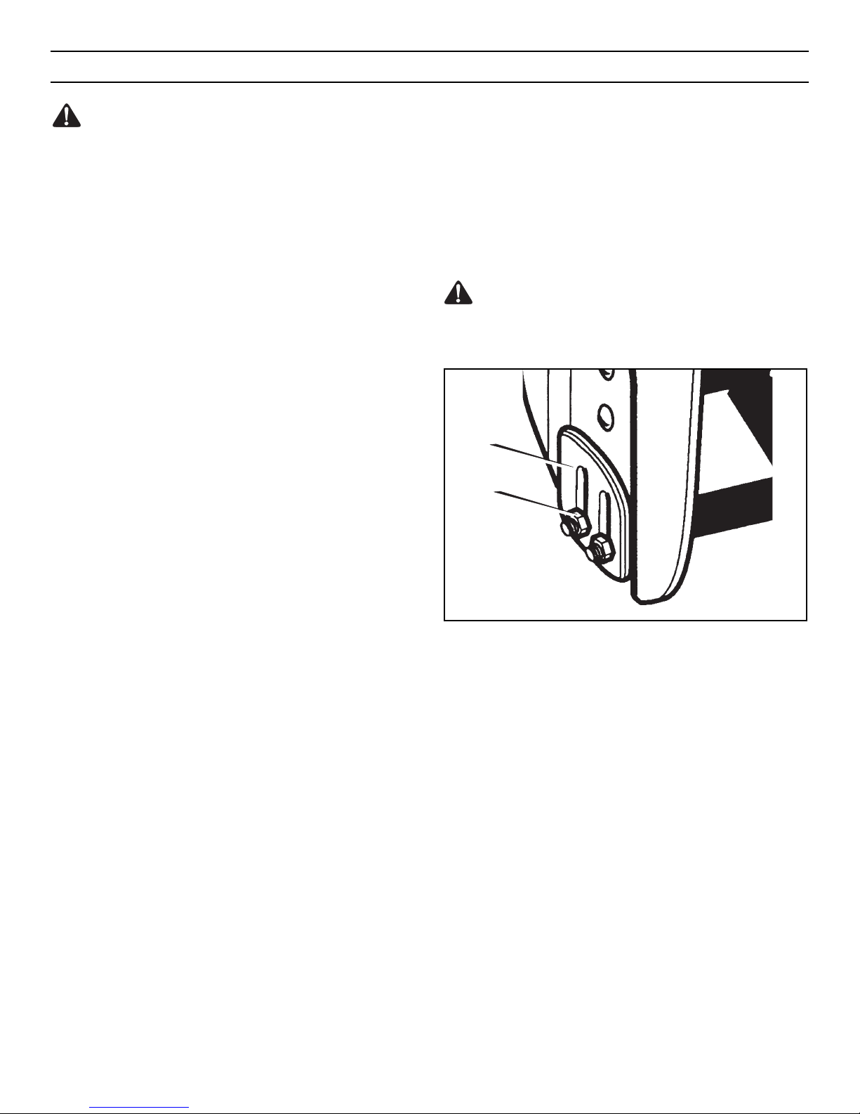
2. Loosen skid mounting nuts (Figure 31) and push the skid
down until it touches the ground. Retighten mounting nuts.
3. Set skid on other side at same height.
NOTE: Make sure that snowthrower is set at same height on both
sides.
WARNING: Be certain to maintain proper ground
clearance for your particular area to be cleared. Objects
such as gravel, rocks or other debris, if struck by the impeller,
may be thrown with sufficient force to cause personal injury,
property dam age or damage to the snowthrower.
Height
Adjust Skid
Skid Mounting
Nuts
Figure 31
MAINTENANCE
27
Page 28
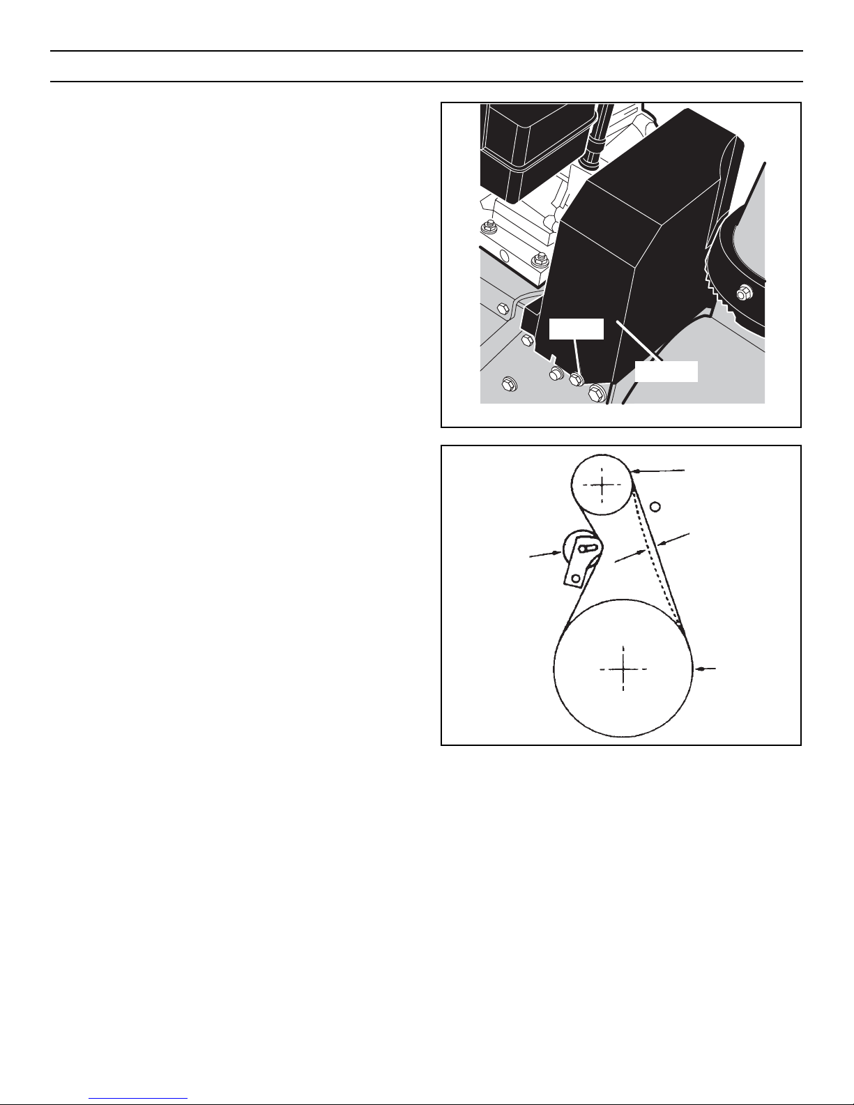
BELT ADJUSTMENT
Traction Drive Belt
The traction drive belt has constant spring pressure and does not
require an adjustment. If the traction drive belt is slipping, replace
the belt. See “How To Replace The Belts” in this section.
Auger Drive Belt
If your snowthrower will not discharge snow, check the control
cable adjustment. If it is correct, then check the condition of the
auger drive belt. If it is damaged or loose, replace it (see “Belt
Replacement” in this section of the manual).
1. Disconnect spark plug wire.
2. Remove screw from belt cover. Remove belt cover (see
Figure 32).
3. Loosen nut on auger idler pulley and move auger idler pulley
towards belt about 1/8 inch (3 mm) (see Figure 36).
4. Tighten nut.
5. Have someone engage auger drive clutch. Check tension on
belt (opposite idler pulley). Belt should deflect about 1/2 inch
(12.5 mm) with moderate pressure (Figure 33). You may have
to move idler pulley more than once to obtain the correct tension.
6. Reinstall belt cover.
7. Whenever belts are adjusted or replaced, the cables will need
to be adjusted. (See “Cable Adjustment” in this section of the
manual).
8. Attach the spark plug wire.
Figure 33
Idler Pulley
Engaged
Auger Drive
Engine Pulley
1/2 inch
(12.5 mm)
Deflection
Impeller
Pulley
Figure 32
Belt Cover
Screw
MAINTENANCE
28
Page 29
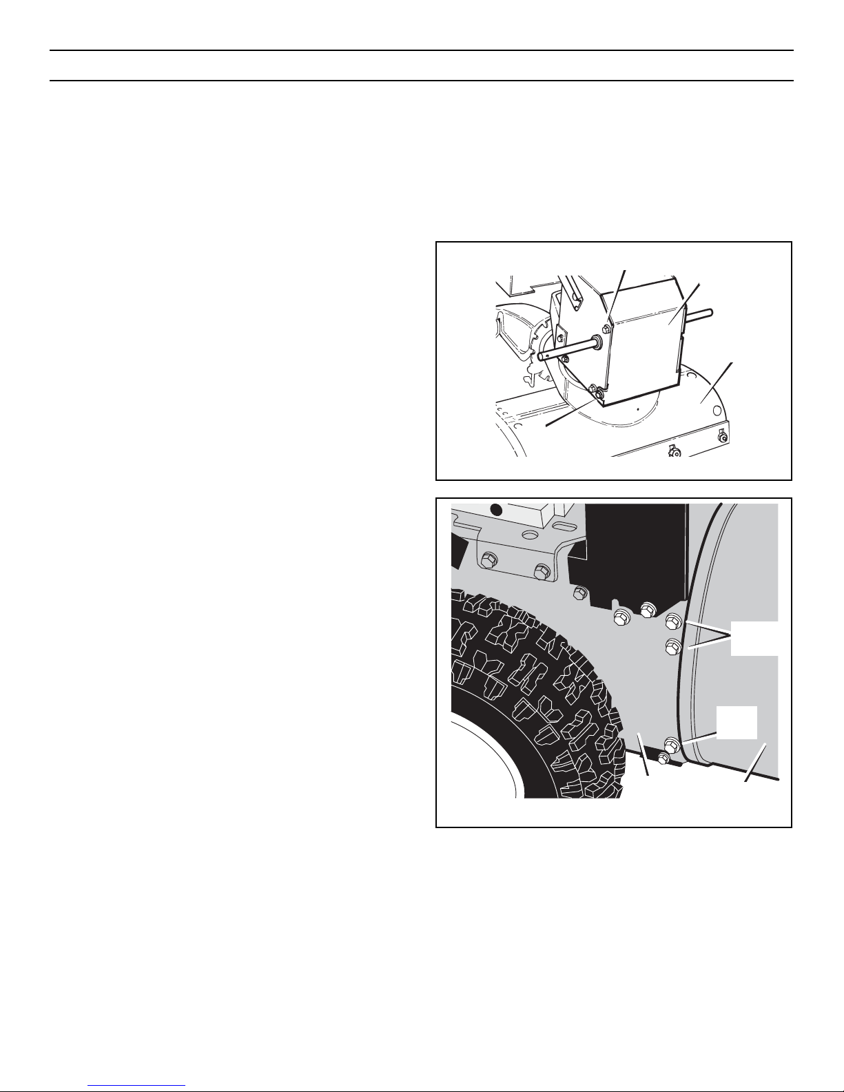
HOW TO REPLACE THE BELTS
The drive belts are of special construction and must be replaced
with original factory replacement belts available from your nearest
authorized service center.
Some steps require the assistance of a second person.
How To Remove the Auger Drive Belt
If the auger drive belt is damaged, the snowthrower will not discharge snow. Replace the damaged belt as follows.
1. Disconnect the spark plug wire.
2. Loosen the bolts on each side of the bottom panel (see
Figure 34).
3. Remove the bottom panel.
4. Remove screw from belt cover. Remove the belt cover (see
Figure 32).
5. Loosen the belt guide. Pull the belt guide away from the
auger drive pulley (see Figure 36).
6. Pull the idler pulley away from the auger drive belt and slip
the auger drive belt off of the idler pulley.
7. Remove the auger drive belt from the engine pulley. To
remove the auger drive belt, the engine pulley may have to
be partially rotated.
8. Remove the top four bolts that hold together the auger hous-
ing and the motor box. Loosen the bottom two bolts. The
auger housing and the motor box can now be split apart for
removal of the belt (see Figure 35).
9. Remove the old auger drive belt from the auger drive pulley.
Replace the auger drive belt with an original factory replacement belt available from an authorized service center (see
Figure 36).
10. Install the new auger drive belt onto the auger drive pulley.
NOTE: To assemble the auger housing to the motor box,
have someone hold the auger clutch lever in the ENGAGED
position. This will move the idler arm and pulley enough to
allow the auger drive pulley to move back into position.
11. Assemble the auger housing to the motor box with the four
bolts that were removed in step 8. Tighten the bottom two
bolts.
12. Install the auger drive belt onto the engine pulley.
13. Slip the auger drive belt under the idler pulley.
14. Adjust the auger drive belt. See “How To Adjust The Auger
Drive Belt” in this section.
15. Adjust the belt guide. See “How To Adjust The Belt Guide” in
this section.
16. Install the belt cover. Tighten screw (see Figure 32).
17. Check the adjustment of the cables. See “How To Check And
Adjust The Cables” in this section.
18. Install the bottom panel (see Figure 34).
19. Tighten the bolts on each side of the bottom panel.
20. Connect the spark plug wire.
Bolt
Figure 35
Remove
Bolts
Loosen
Bolts
Auger Housing
Motor
Box
Figure 34
Bottom Panel
Auger Housing
Bolt
MAINTENANCE
29
Page 30
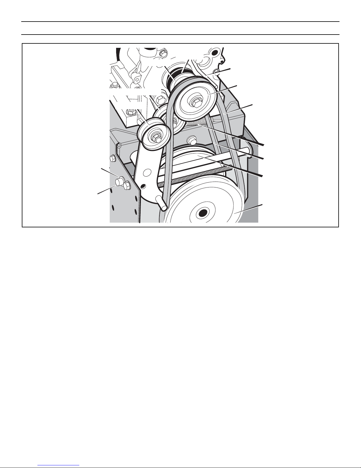
Figure 36
Swing Plate Axle Rod
E-Ring
Engine Pulley
Traction Drive Pulley
Traction Drive Belt
Traction Drive Spring
Auger Drive Belt
Auger Drive Pulley
Belt Guide
Traction
Drive Belt
Engine Pulley
Traction Drive Idler Pulley
Idler Pulley
MAINTENANCE
30
Page 31
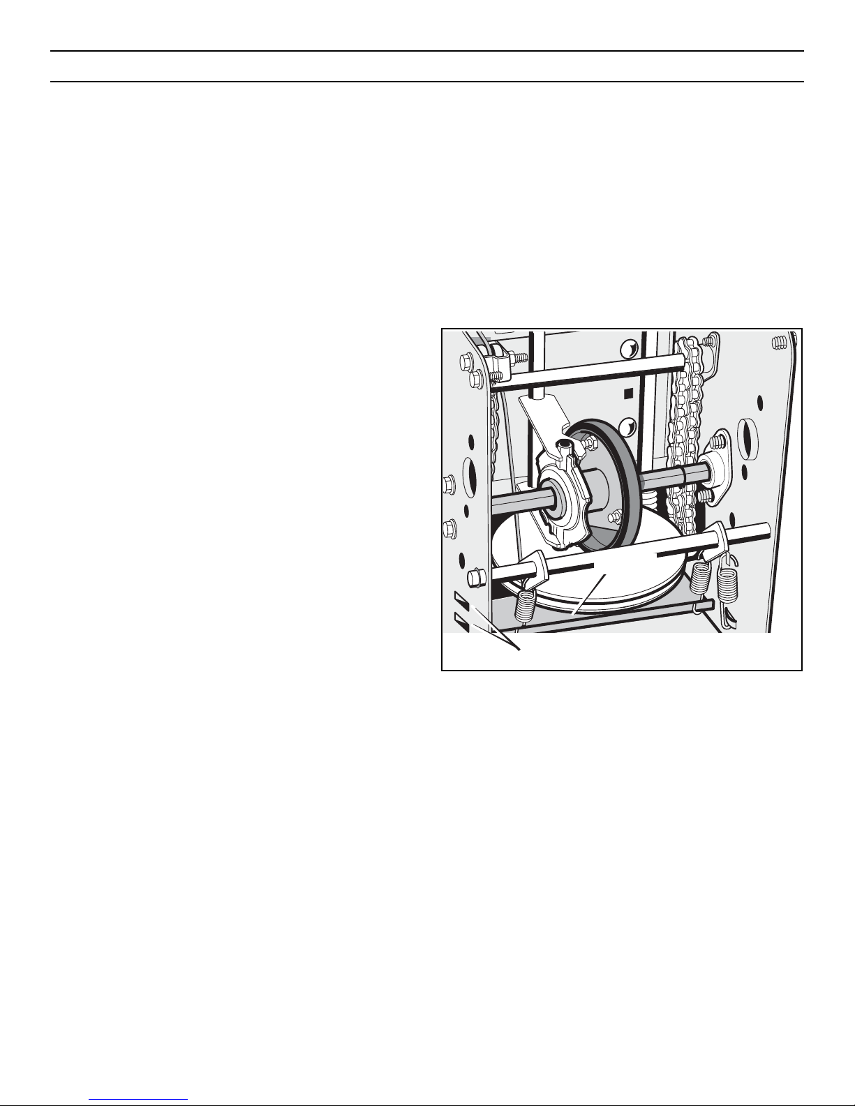
How To Remove the Traction Drive Belt
If the snowthrower will not move forward, check the traction drive
belt for wear or damage. If the traction drive belt is worn or damaged, replace the belt as follows.
1. Disconnect the spark plug wire.
2. Remove the auger drive belt. See “How To Remove The Auger
Drive Belt” in this section.
3. Remove the e-ring from one end of the swing plate axle rod.
Remove the swing plate axle rod to allow the swing plate to
pivot forward (see Figure 36).
4. Remove the traction drive spring.
5. Remove the old traction drive belt from the traction drive
pulley and from the engine pulley. Replace the traction drive
belt with an original factory replacement belt available from an
authorized service center.
6. Install the new traction drive belt onto the traction drive pul-
ley and onto engine pulley.
7. Make sure the traction drive idler pulley is properly aligned
with the traction drive belt.
8. Attach the traction drive spring.
9. Install the swing plate axle rod and secure with the e-ring
removed earlier.
10. The bottom of the swing plate must be positioned between
the alignment tabs. Make sure the swing plate is properly
secured (see Figure 37).
NOTE: If the drive will not engage after the traction drive
belt has been replaced, then check to make sure that the
swing plate is positioned between the alignment tabs.
11. Install and adjust the auger drive belt. See “How To Remove
The Auger Drive Belt” in this section.
12. Adjust the belt guide. See “How To Adjust The Belt Guide” in
this section.
13. Install the bottom panel (see Figure 34).
14. Tighten the bolts on each side of the bottom panel.
15. Install the belt cover. Tighten screw (see Figure 32).
16. Check the adjustment of the cables. See “How To Check And
Adjust The Cables” in this section.
17. Connect the spark plug wire.
Figure 37
Swing Plate
Alignment Tabs
MAINTENANCE
31
Page 32
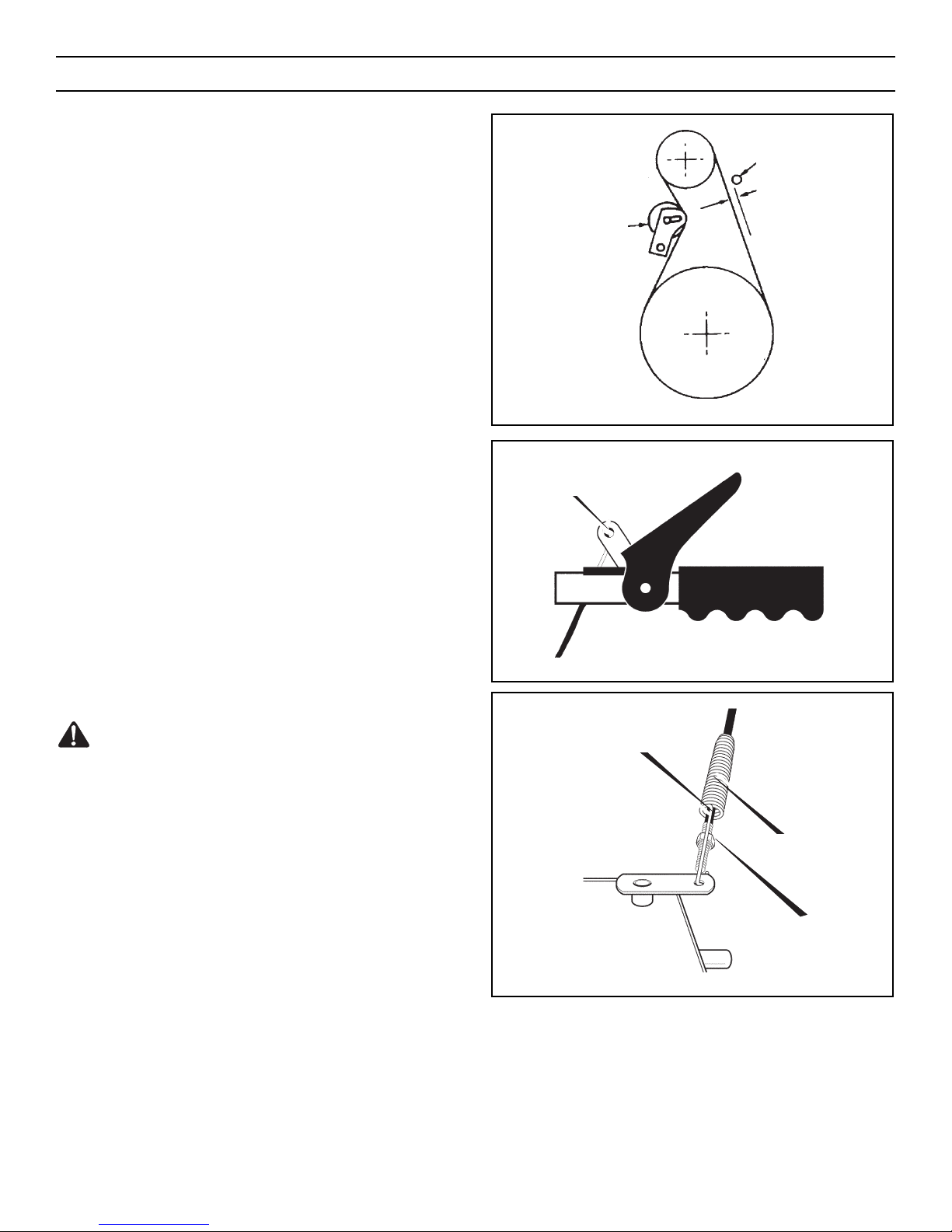
BELT GUIDE ADJUSTMENT
1. Remove spark plug wire.
2. Have someone engage auger drive.
3. Measure the distance between the belt guide and belt. The distance should be 1/8 inch (3 mm) for guide. See Figure 38.
4. If adjustment is necessary, loosen belt guide mounting bolt.
Move belt guide to the correct position. Tighten mounting
bolt.
5. Reinstall belt cover.
6. Reconnect spark plug wire.
HOW TO CHECK AND ADJUST THE CABLES
The cables are adjusted at the factory and no adjustment should be
necessary. If the cables have become stretched or are sagging,
adjustment will be necessary.
Whenever belts are adjusted or replaced, the cables will need to be
adjusted.
To check for correct adjustment, unhook “Z” fitting at clutch
lever (see Figure 39).
1. Move clutch lever to the full forward position (just contacting
plastic bumper). Holding cable tight, note position of fitting to
hole in clutch lever.
2. The center of the “Z” fitting should be between the center and
top of the hole in the clutch lever. Adjust either the auger drive
cable or the traction drive cable as follows.
Auger Drive Cable Adjustment
WARNING: Drain the gasoline outdoors, away from fire or
flame.
1. Remove the gas from the gas tank. Stand the snowthrower up
on the front end of the auger housing.
2. Push cable through spring to expose the threaded portion of
the cable (see Figure 40).
3. Hold square end of threaded portion with pliers and adjust
locknut in or out until correct adjustment is reached. Pull
cable back through spring and connect cable.
Figure 40
Cable Spring
Locknut
Square End
Figure 39
“Z” Fitting
Figure 38
Belt Guide
1/8 Inch (3 mm)
Auger Idler
Pulley Engaged
MAINTENANCE
32
Page 33
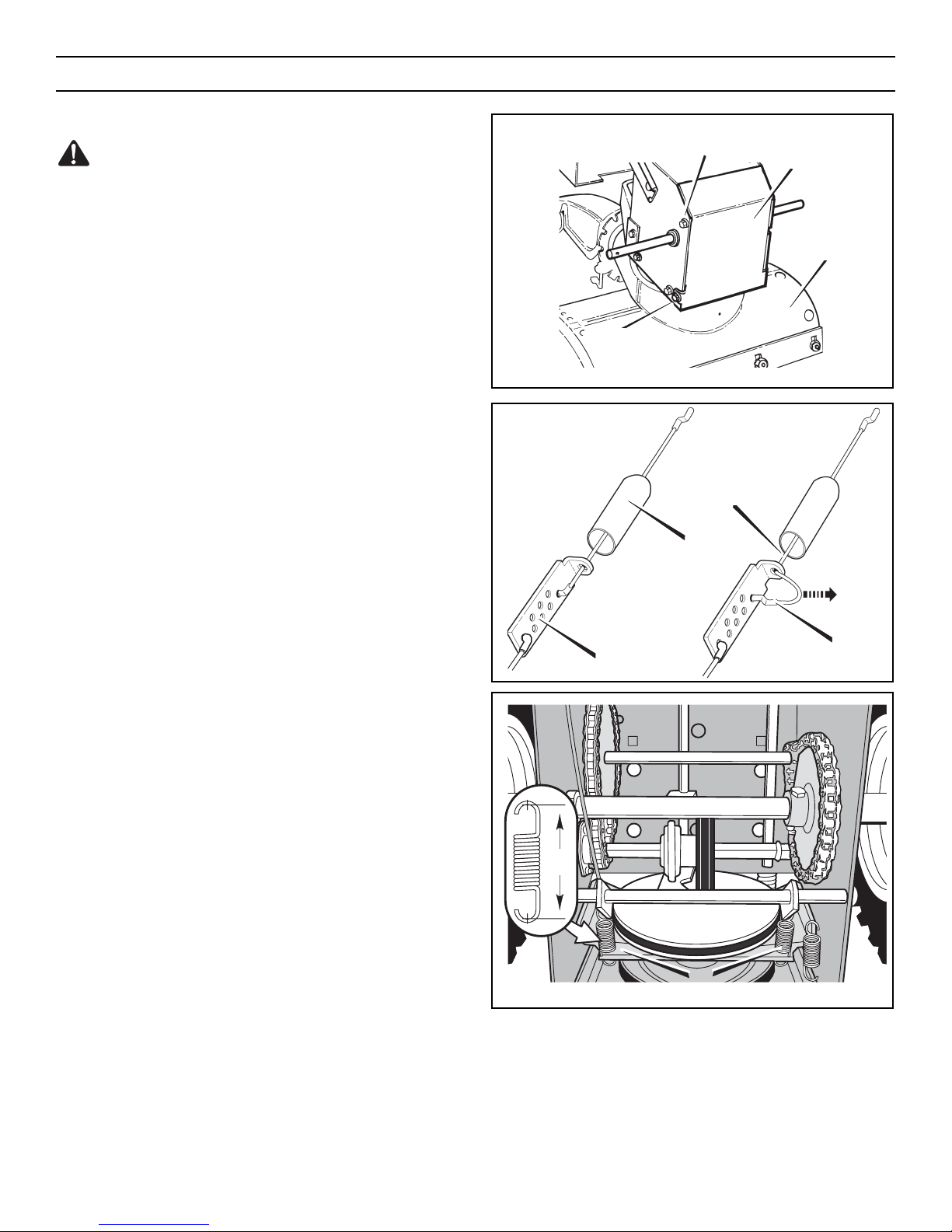
TRACTION DRIVE CABLE ADJUSTMENT
WARNING: Drain the gasoline outdoors, away from fire or
flame.
1. Remove the gas from the gas tank. Stand the snowthrower up
on the front end of the auger housing.
2. Loosen the bolts on each side of the bottom panel (see
Figure 41).
3. Remove the bottom panel.
4. Disconnect the “Z” fitting from the drive lever (see Figure
39).
5. Slide the cable boot off the cable adjustment bracket (see
Figure 42).
6. Push the bottom of the traction drive cable through the cable
adjustment bracket until the “Z” hook can be removed.
7. Remove the “Z” hook from the cable adjustment bracket.
Move the “Z” hook down to the next adjustment hole.
8. Pull the traction drive cable up through the cable adjustment
bracket.
9. Put the cable boot over the cable adjustment bracket.
10. Install the “Z” hook to the traction drive lever (see Figure 39).
11. To check the adjustment, depress the drive lever and check the
length of the drive spring (see Figure 43). In correct adjustment, the length of the drive spring is minimum 3 inches
(76 mm) maximum 3-3/8 inches (85 mm).
12. Install the bottom panel (see Figure 41).
13. Tighten the bolts on each side of the bottom panel.
Figure 43
Drive Spring
Figure 42
“Z” Hook
Traction Drive Cable
Cable Boot
Cable Adjustment
Bracket
Figure 41
Auger
Housing
Bottom Panel
Bolt
Bolt
MAINTENANCE
33
“A”
Page 34
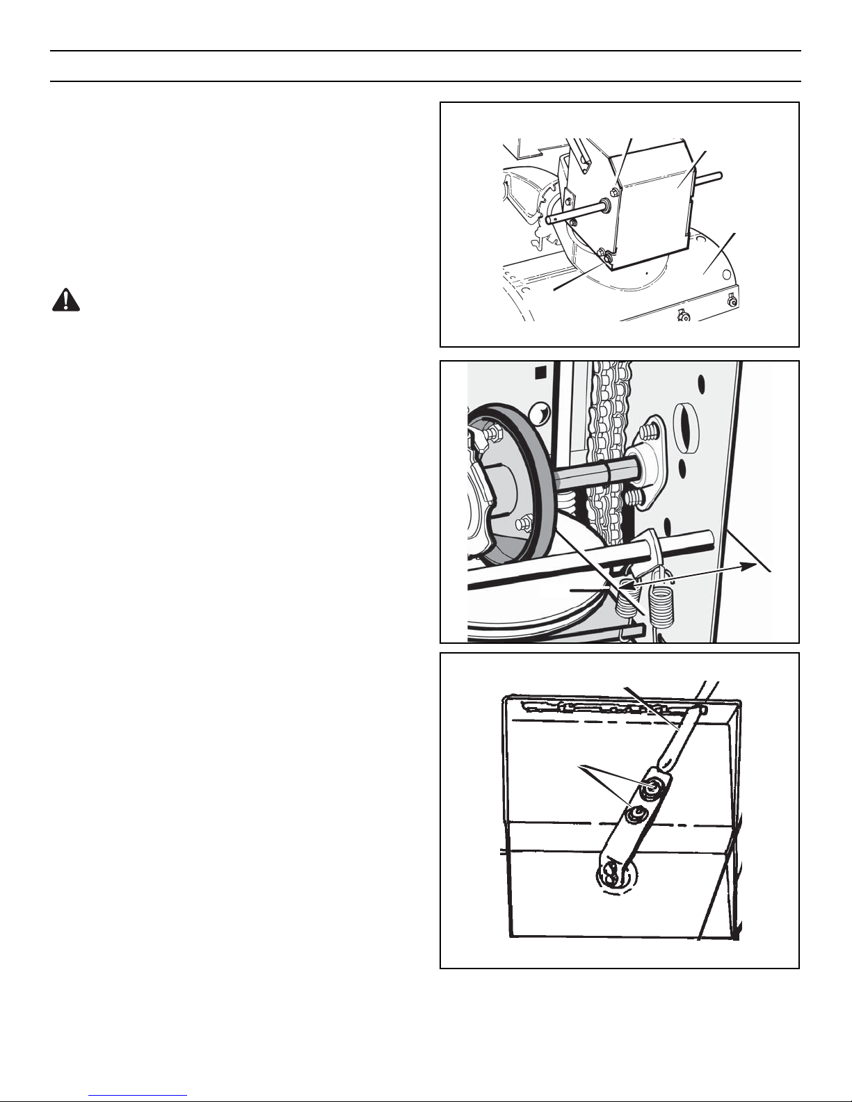
HOW TO ADJUST OR REPLACE THE FRICTION WHEEL
How To Check The Friction Wheel
If the snowthrower will not move forward, check the traction drive
belt, the traction drive cable or the friction wheel. If the friction
wheel is worn or damaged, it must be replaced. See “How To
Replace the Friction Wheel” in this section. If the friction wheel is
not worn or damaged, check as follows.
1. Remove the gas from the gas tank. Stand the snowthrower up
on the front end of the auger housing (see Figure 44).
WARNING: Drain the gasoline outdoors, away from fire or
flame.
2. Disconnect the spark plug wire.
3. Loosen the bolts on each side of the bottom panel (see
Figure 44).
4. Remove the bottom panel.
5. Position the shift speed lever in the lowest forward speed.
6. Note the position of the friction wheel (see Figure 45). The
correct distance “A” from the right side of the friction wheel
to the outside of the motorbox is as follows:
Tire Size Distance “A”
12 and 13 inch 4-1/8" (10.5 cm)
16 inch 4-5/16" (10.95 cm)
If the friction wheel is not in the correct position, adjust as
follows.
How To Adjust The Friction Wheel
1. Position the shift speed lever in the lowest forward speed.
2. Loosen the bolts on the speed control rod (see Figure 46).
3. Move the friction wheel to the correct position (see Figure
45).
4. Tighten the bolts on the speed control rod (see Figure 46).
5. Install the bottom panel (see Figure 44).
6. Tighten the bolts on each side of the bottom panel.
Figure 46
Loosen Bolts
Speed Control Rod
Figure 45
Figure 44
Auger
Housing
Bottom Panel
Bolt
Bolt
MAINTENANCE
34
“A”
Page 35
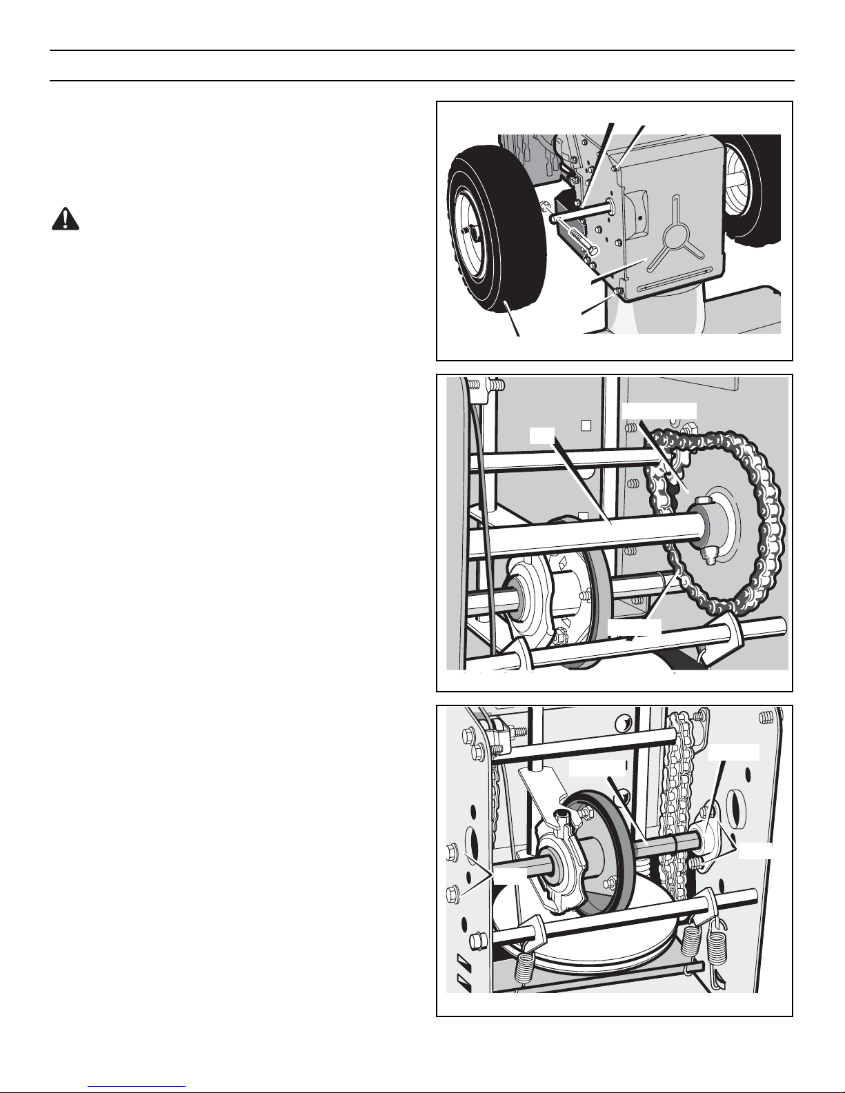
How To Replace The Friction Wheel
If the friction wheel is worn or damaged, the snowthrower will not
move forward. The friction wheel must be replaced as follows.
1. Remove the gas from the gas tank. Stand the snowthrower up
on the front end of the auger housing (4) (see Figure 44).
WARNING: Drain the gasoline outdoors, away from fire or
flame.
2. Disconnect the spark plug wire.
3. Remove the fasteners that secure the left wheel. Remove the
left wheel from the axle (see Figure 47).
4. Loosen the bolts on each side of the bottom panel.
5. Remove the bottom panel.
6. Remove the fasteners that secure the drive sprocket to the
axle (see Figure 48).
7. Remove the right wheel, axle, and drive sprocket.
8. Remove the four bolts that hold the bearings on each side of
the hex shaft (see Figure 49).
9. Remove the hex shaft and bearings.
NOTE: Take special note of the position of the washers on
the hex shaft.
Figure 49
Bolts
Bolts
Hex Shaft
Bearings
Figure 48
Chain
Drive Sprocket
Axle
Figure 47
Bottom
Panel
Wheel
Axle
Bolt
Bolt
MAINTENANCE
35
Page 36
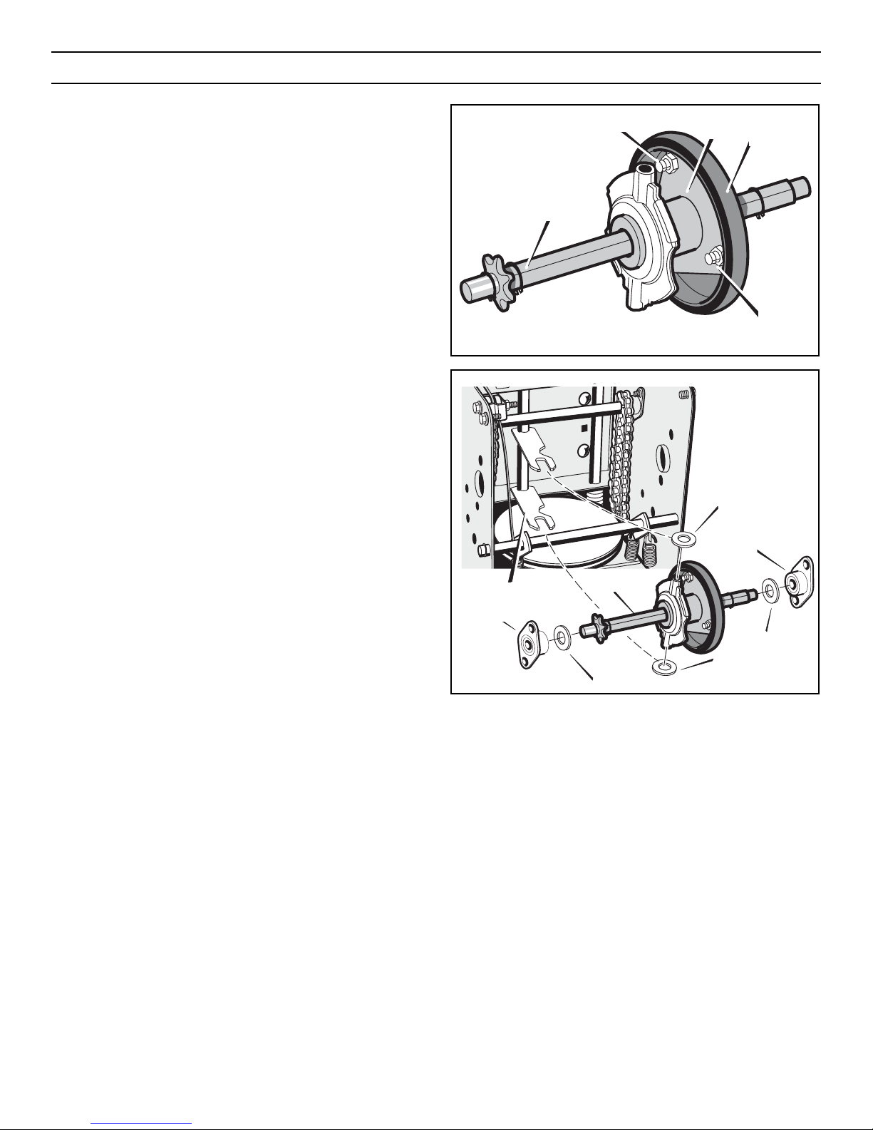
10. Remove the three fasteners that hold the friction wheel to the
hub (see Figure 50).
11. Remove the friction wheel from the hub. Slip the friction
wheel off the hex shaft.
12. Assemble the new friction wheel onto hub with the fasteners
removed earlier.
13. Install the hex shaft and bearings with the four bolts removed
earlier (see Figure 51).
Make sure the washers are properly installed in the original
position. Also, make sure the two washers are properly
aligned with the actuator arms.
14. Make sure the hex shaft turns freely.
15. Install the right wheel, axle, and drive sprocket with the fasteners removed earlier. Install the chain onto the drive sprock-
et (see Figure 48).
16. Check the adjustment of the friction wheel. See “How To
Adjust The Friction Wheel” in this section.
17. Make sure the friction wheel and the disc drive plate are free
from grease or oil.
18. Install the bottom panel (see Figure 47).
19. Tighten the bolts on each side of the bottom panel.
20. Install the left wheel to the axle with the fasteners removed
earlier.
21. Connect the spark plug wire.
Figure 51
Washer
Bearings
Washer
Washer
Washer
Actuator Arms
Bearings
Hex Shaft
Figure 50
Fasteners
Hub
Friction
Wheel
Hex Shaft
Fasteners
MAINTENANCE
36
Page 37
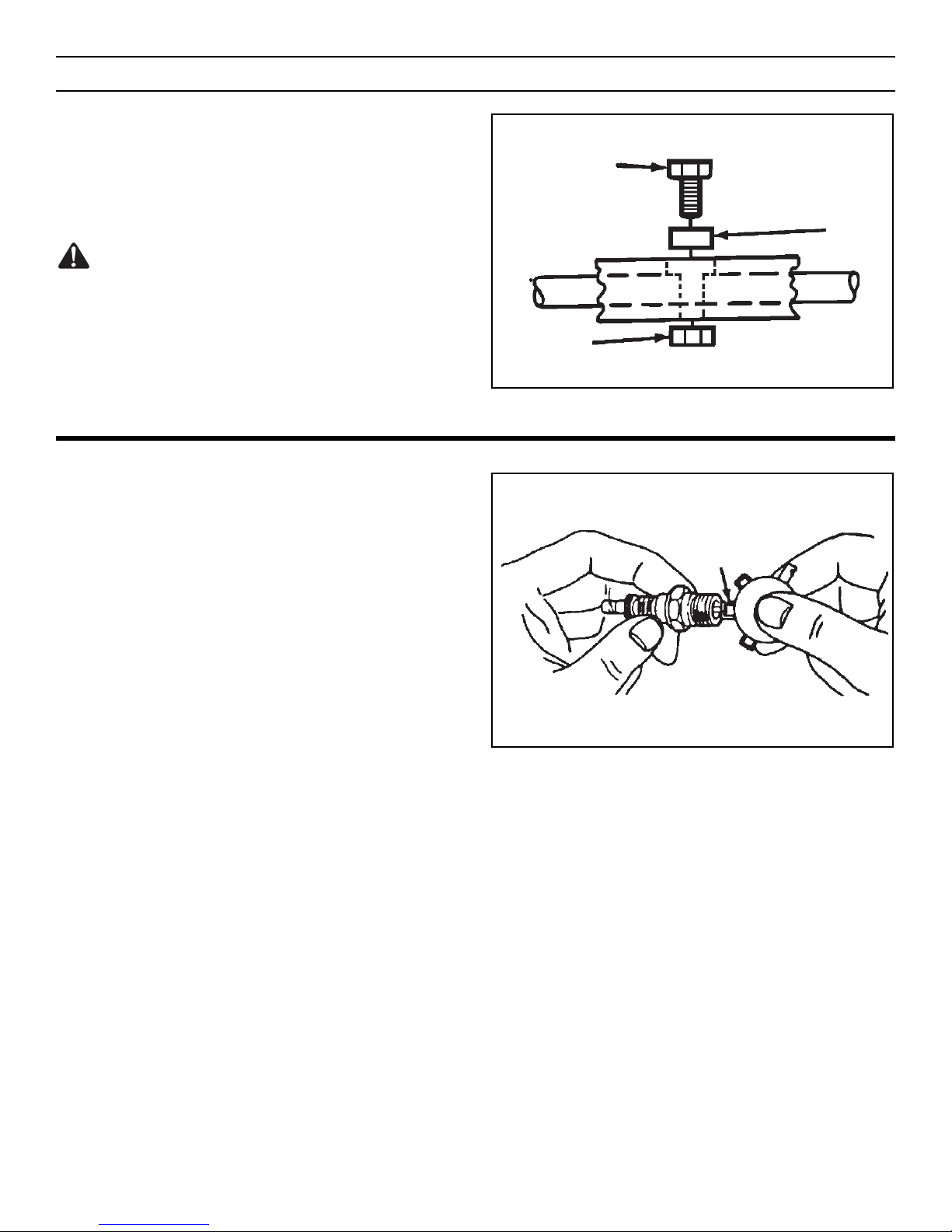
AUGER SHEAR BOLT REPLACEMENT
The augers are secured to the auger shaft with special bolts that
are designed to break if an object becomes lodged in the auger
housing. Use of a harder bolt will reduce the protection provided
by the shear bolt. To replace a broken shear bolt, proceed as follows:
WARNING: To insure safety and performance levels, only
original replacement shear bolts should be used.
1. Stop the engine, disengage all controls, disconnect the spark
plug lead wire, and make sure all moving parts have stopped.
2. Align the hole in the auger with the hole in the auger shaft.
Install new shear bolt, spacer and locknut found in the toolbox
located on the belt cover (see Figure 52).
NOTE: The spacer fits into the larger hole in the auger tube.
Figure 52
Spacer
Locknut
Shear Bolt
MAINTENANCE
37
TO ADJUST OR REPLACE THE SPARK PLUG
Check the spark plug every twenty-five (25) hours. Replace the
spark plug if the electrodes are pitted or burned or if the porcelain
is cracked.
1. Clean spark plug and reset gap periodically.
2. Clean area around spark plug base before removal, to prevent
dirt from entering engine.
3. Replace spark plug if electrodes are pitted or burned or if
porcelain is cracked.
4. Clean spark plug by carefully scraping electrodes (do not
sandblast or use wire brush).
5. Be sure spark plug is clean and free of foreign material. Check
electrodes gap with a wire feeler gauge and reset gap to 0.030"
(0.76 mm) if necessary. If a new spark plug is needed, refer to
REPLACEMENT PARTS Parts section of this manual for proper replacement spark plug.
6. Before installing spark plug, coat threads lightly with graphite
grease to insure easy removal.
7. Tighten plug firmly into engine. If torque wrench is available,
torque plug to 18-23 ft-lbs. (24.2-31.2 Nm).
Figure 53
0.030" (0.76 mm)
Gap
Page 38

OFF SEASON STORAGE
WARNING: Never store the engine, with fuel in the tank,
indoors or in a poor ventilated enclosure where fuel
fumes could reach an open flame, spark or pilot light as on a
furnace, water heater, clothes dryer, etc.
Handle gasoline carefully. It is highly flammable and careless
use could result in serious fire damage to your person and/or
property.
Drain fuel into approved containers outdoors, away from open
flame.
If the snowthrower is to be stored for thirty (30) days or more at
the end of the snow season, the following steps are recommended
to prepare your snowthrower for storage.
NOTE: Gasoline must be removed or treated to prevent gum
deposits from forming in the tank, filter, hose, and carburetor
during storage.
1. To remove gasoline, run engine until tank is empty and engine
stops.
If you do not want to remove the gasoline, add fuel stabilizer to any
gasoline left in the tank to minimize gum deposits and acids. If the
tank is almost empty, mix stabilizer with fresh gasoline in a separate container and add some to the tank. ALWAYS FOLLOW
INSTRUCTIONS ON STABILIZER CONTAINER. THEN RUN ENGINE
AT LEAST 10 MINUTES AFTER STABILIZER IS ADDED TO ALLOW
MIXTURE TO REACH CARBURETOR. STORE SNOWTHROWER IN
SAFE PLACE.
2. You can help keep your engine (4-cycles only) in good operating condition by changing oil before storage.
3. Lubricating the piston/cylinder area. This can be done by first
removing the spark plug and squirting clean engine oil into the
spark plug hole. Then cover the spark plug hole with a rag to
absorb oil spray. Next, rotate the engine by pulling the starter
two or three times. Finally, reinstall spark plug and attach
spark plug wire.
4. Thoroughly clean the snowthrower.
5. Lubricate all lubrication points (see “Lubrication“ in the
MAINTENANCE section).
6. Insure that all nuts, bolts, and screws are securely fastened.
Inspect all visible moving parts for damage, breakage, and
wear. Replace if necessary.
7. Touch up all rusted or chipped paint surfaces; sand lightly
before painting.
8. Cover the bare metal parts of the snowthrower housing auger,
and the impeller with rust preventative.
9. If possible, store your snowthrower indoors and cover it to
give protection from dust and dirt.
10. On models with folding handles, loosen the knobs that secure
the upper handle. Rotate the upper handle back.
11. If the machine must be stored outdoors, block up the
snowthrower and insure the entire machine is off the ground.
Cover the snowthrower with a heavy tarpaulin.
REMOVING THE SNOWTHROWER FROM STORAGE
When removing the snowthrower from storage, follow the steps
below.
1. Put the upper handle in the operating position, tighten the
knobs that secure the upper handle.
2. Fill the fuel tank with a fresh fuel.
3. Check the spark plug. Make sure the gap is correct. If the
spark plug is worn or damaged, replace before using.
4. Make sure all fasteners are tight.
5. Make sure all guards, shields, and covers are in place.
6. Make sure all adjustments are correct.
STORAGE
38
Page 39

Identifying Your Snowthrower
Your new Snowthrower has two (2) identifying numbers: (1) unit model number: (2) unit serial number. The two preceding numbers are
required to insure that the proper replacement parts are obtained when required. If you have any questions concerning parts, service, or
technical data, contact your nearest John Deere/Frontier dealer. For complete warranty information refer to the warranty in the OWNER’S
INFORMATION section of this manual.
PROBLEM LOOK FOR REMEDY
Difficult starting Defective spark plug. Replace defective spark plug.
Engine runs erratically Blocked fuel line. Clean fuel line.
Empty gas tank. Check fuel supply.
Stale gasoline. Add fresh gasoline with fuel stabilizer.
Water or dirt in fuel system. Remove carburetor bowl to drain fuel tank. Refill with fresh fuel.
CAUTION: Do not remove carburetor bowl when the engine is hot.
Engine stalls Unit running on CHOKE. Set choke lever to RUN position.
Loss of power Gas cap vent hole is
plugged.
Remove ice and snow from cap. Be sure vent hole is clear.
Excessive vibration Loose parts or damaged
impeller.
Stop engine immediately and remove spark plug wire. Tighten all bolts
and make all necessary repairs. If vibration continues, have the unit
serviced by a competent repairman.
Unit fails to propel itself Drive belt loose or damaged. Replace drive belt. Refer to “Drive Belt Replacement” in the
MAINTENANCE section of this manual.
Incorrect adjustment of
traction drive cable.
Adjust traction drive cable. Refer to “Cable Adjustment” in the
MAINTENANCE section of this manual.
Worn or damaged friction
disc.
Replace friction disc. Refer to “Friction Wheel Replacement” in the
MAINTENANCE section of this manual.
Unit fails to discharge
snow
Auger drive belt loose or
damaged.
Replace or adjust auger drive belt. Refer to “Drive Belt Replacement” and
“Drive Belt Adjustment” in the MAINTENANCE section of this manual.
Auger control cable not
adjusted correctly.
Adjust auger control cable. Refer to “Cable Adjustment” in the
MAINTENANCE section of this manual.
Broken shear bolt. Replace shear bolt. Refer to “Auger Shear Bolt Replacement” in the
MAINTENANCE section of this manual.
Discharge chute clogged. Stop engine immediately and disconnect spark plug wire. Refer to the
first WARNING in “Snowthrower Operation” in the OPERATION section
of this manual. Clean discharge chute and inside of auger housing.
Foreign object lodged in
auger.
Stop engine immediately and disconnect spark plug wire. Refer to the
third WARNING in “Snowthrower Operation” in the OPERATION section
of this manual. Remove object from auger.
TROUBLE SHOOTING CHART
39
Page 40

NOTES
40
Page 41

NOTES
41
Page 42

WE RECOMMEND JOHN DEERE/FRONTIER quality parts and lubricants available at your John Deere/Frontier dealer.
PART NUMBERS MAY CHANGE. When you order replacement
parts, use the part numbers listed below and in the Parts Manual.
If a part number changes, your John Deere/Frontier dealer will
have the latest part number.
WHEN YOU ORDER PARTS, your John Deere/Frontier dealer must
have your snowthrower model and serial number and your engine
model number. This is the model and serial number that
you recorded in the OWNER’S INFORMATION section of this
OPERATOR’S MANUAL.
QUICK REFERENCE PART NUMBERS
The following is a list of replacement parts that you may need for
routine service and maintenance. If you do not see the replacement
part you need in the following chart, see your dealer.
* Part Numbers are subject to change without notice.
ITEM PART NUMBER *
Belt, Drive MT579932
Belt, Auger MT37x120
Scraper Blade MT581397E701
Skid Shoe MT1502079E701
Spark Plug Champion RC12YC
REPLACEMENT PARTS
42
Page 43

Engine Briggs & Stratton
Horsepower 6.5 hp
Starter Electric / Recoil
Fuel Capacity 3 quarts
Drive System Friction Disc
Speeds 6 Forward / 2 Reverse
Tire Diameter 13"
Traction Control Pin Lock
Clearing Width 24"
Housing Height 17.5"
Auger Diameter 10"
Auger Type Steel / Notched
Impeller Diameter 9"
Chute Rotation Remote
Chute Turning Radius 190°
Deflector Control Manual
Weight 160 lbs
Warranty — Engine 3 years
Warranty — Machine 3 years
SPECIFICATIONS ST6524
43
Page 44

 Loading...