

Page 1

Operating
Instructions
Testbox Drahtpuffer
Wire buffer test box
Bedienungsanleitung
DE
Operating Instructions
EN
42,0410,1545 003-25112022
Page 2

Page 3

Inhaltsverzeichnis
Testbox Drahtpuffer 4
Sicherheit 4
Allgemeines 4
Gerätekonzept 4
Bedienelemente und Anschlüsse 5
Mess- und Prüfmittel 5
Drahtpuffer eines Robacta Drive CMT-Schlauchpaketes überprüfen 6
Vorbereitung 6
Drahtpuffer überprüfen 7
Drahtpuffer eines PullMig CMT-Schlauchpaketes überprüfen 8
Allgemeines 8
Vorbereitung 8
Drahtpuffer überprüfen 10
Fehlermeldungen überprüfen 11
Sicherheit 11
Vorbereitung 11
Fehlermeldungen überprüfen 11
Schaltplan 13
DE
3
Page 4

Testbox Drahtpuffer
Sicherheit
WARNUNG!
Gefahr durch Fehlbedienung und fehlerhaft durchgeführte Arbeiten.
Schwere Personen- und Sachschäden können die Folge sein.
Alle in diesem Dokument beschriebenen Arbeiten und Funktionen dürfen
▶
nur von technisch geschultem Fachpersonal ausgeführt werden.
Dieses Dokument vollständig lesen und verstehen.
▶
Sämtliche Sicherheitsvorschriften und Benutzerdokumentationen dieses
▶
Gerätes und aller Systemkomponenten lesen und verstehen.
WARNUNG!
Gefahr durch elektrischen Strom.
Schwere Personen- und Sachschäden können die Folge sein.
Vor Beginn der Arbeiten alle beteiligten Geräte und Komponenten ausschal-
▶
ten und von Stromnetz trennen.
Alle beteiligten Geräte und Komponenten gegen Wiedereinschalten sichern.
▶
Nach dem Öffnen des Gerätes mit Hilfe eines geeigneten Messgerätes si-
▶
cherstellen, dass elektrisch geladene Bauteile (beispielsweise Kondensatoren) entladen sind.
Allgemeines Sollten bei den Überprüfungen Fragen auftreten, steht Ihnen ein Experten-Team
zur Verfügung.
E-Mail: welding.techsupport@fronius.com
Gerätekonzept Die Testbox Drahtpuffer dient zur Überprüfung der Ausgangssignale des Draht-
puffers. Weiters kann auch die Kommunikation des Drahtpuffers mit der damit
verbundenen Stromquelle überprüft werden.
4
Page 5

Bedienelemente
(6)
(1)
(3)
(2)
(5)
(4)(7)
und Anschlüsse
(1) Verbindungskabel Brenner-
steuerung
zur Verbindung mit einer
Stromquelle, oder einem Drahtvorschub
(2) Verbindungskabel Drahtpuffer
zur Verbindung mit einer
Stromquelle, oder einem Drahtvorschub
(3) BNC-Buchse
zur Messung der Ausgangssignale mittels BNC-Stecker
(4) Anschluss Minuspotential
zur Messung der Ausgangssignale mittels Digital-Multimeter
(5) Anschluss Pluspotential
zur Messung der Ausgangssignale mittels Digital-Multimeter
(6) Anschluss Drahtpuffer
zum Anschließen eines Drahtpuffers
(7) Schalter Guntrigger
zum Auslösen eines
Schweißstarts mittels Testbox
DE
Mess- und
Prüfmittel
CMT Stromquelle + CMT Drahtvorschub oder
-
CMT Prüf-Stromquelle (adaptierte TPS 2700)
-
Digital-Multimeter
-
5
Page 6

Drahtpuffer eines Robacta Drive CMT-Schlauch-
(2)
(1)
(3)
(4)
paketes überprüfen
Vorbereitung
Netzschalter der Stromquelle in
1
Stellung - O - schalten
Stromquelle vom Netz trennen
2
Drahtelektrode aus dem Schlauch-
3
paket entfernen
Schweißbrenner von allen anderen
4
Systemkomponenten trennen
Testbox Drahtpuffer mittels Ver-
5
bindungskabel Drahtpuffer (1) und
Verbindungskabel Brennersteuerung (2) mit Stromquelle oder
Drahtvorschub verbinden
Drahtpuffer mit Testbox Drahtpuf-
6
fer verbinden (3)
Digital-Multimeter für eine Gleich-
7
spannungs- Messung (Volt DC) vorbereiten
Digital-Multimeter an Testbox
8
Drahtpuffer anschließen (4)
6
Page 7

Drahtpuffer
(1)
(2)
überprüfen
WARNUNG!
Gefahr von elektrischem Schlag aufgrund der eingeschalteten Stromquelle.
Schwere Personen- und Sachschäden können die Folge sein.
Während aller Arbeiten: sicherstellen, dass kein Schweißstart durchgeführt
▶
wird,
den Zentralanschluss an der Stromquelle nicht berühren.
▶
Stromquelle mit dem Netz verbin-
1
den
Netzschalter der Stromquelle in
2
Stellung - I - schalten
Drahtpuffer-Hebel (1) bis zum obe-
3
ren Anschlag drücken, um „Drahtpuffer voll“ zu simulieren
Sollwert „Drahtpuffer voll“: 2,34 - 2,46
Volt
DE
Oberer Anschlag Drahtpuffer-Hebel
Unterer Anschlag Drahtpuffer-Hebel
Drahtpuffer-Hebel (2) bis zum un-
4
teren Anschlag drücken, um
„Drahtpuffer leer“ zu simulieren
Sollwert „Drahtpuffer leer“: 0,42 0,54 Volt
Nach beendeter Überprüfung den
5
Originalzustand des Drahtpuffers
wieder herstellen
7
Page 8

Drahtpuffer eines PullMig CMT-Schlauchpaketes
1
überprüfen
Allgemeines Um die Ausgangssignale des Drahtpuffers in Verbindung mit einem PullMig CMT
-Schlauchpaket überprüfen zu können, muss die Steuerleitung des Drahtpuffers
gewechselt werden.
WICHTIG! Die Steuerleitung Drahtpuffer Art. Nr. 43,0004,2803 ist nicht im Lieferumfang der Testbox Drahtpuffer enthalten.
Verwendete Symbole
Brennerseitig
Vorschubseitig
Vorbereitung
Netzschalter der Stromquelle in Stellung - O - schalten
1
Stromquelle vom Netz trennen
2
Drahtelektrode aus dem Schlauchpaket entfernen
3
Schweißbrenner von allen anderen Systemkomponenten trennen
4
Abdeckung der Steuerleitung ent-
5
fernen
Vorhandene Steuerleitung des
6
Drahtpuffers abstecken
Steuerleitung Drahtpuffer Art. Nr.
7
43,0004,2803 vorübergehend am
Drahtpuffer anschließen
8
Page 9

(2)
(1)
Testbox Drahtpuffer mittels Ver-
(3)
(4)
8
bindungskabel Drahtpuffer (1) und
Verbindungskabel Brennersteuerung (2) mit Stromquelle oder
Drahtvorschub verbinden
Drahtpuffer mit Testbox Drahtpuf-
9
fer verbinden (3)
Digital-Multimeter für eine Gleich-
10
spannungs-Messung (Volt DC) vorbereiten
DE
Digital-Multimeter an Testbox
11
Drahtpuffer anschließen (4)
9
Page 10

Drahtpuffer
(1)
(2)
überprüfen
WARNUNG!
Gefahr von elektrischem Schlag aufgrund der eingeschalteten Stromquelle.
Schwere Personen- und Sachschäden können die Folge sein.
Während aller Arbeiten: sicherstellen, dass kein Schweißstart durchgeführt
▶
wird,
den Zentralanschluss an der Stromquelle nicht berühren.
▶
Stromquelle mit dem Netz verbin-
1
den
Netzschalter der Stromquelle in
2
Stellung - I - schalten
Drahtpuffer-Hebel (1) bis zum obe-
3
ren Anschlag drücken, um „Drahtpuffer voll“ zu simulieren
Sollwert „Drahtpuffer voll“: 2,34 - 2,46
Volt
Oberer Anschlag Drahtpuffer-Hebel
Unterer Anschlag Drahtpuffer-Hebel
Drahtpuffer-Hebel (2) bis zum un-
4
teren Anschlag drücken, um
„Drahtpuffer leer“ zu simulieren
Sollwert „Drahtpuffer leer“: 0,42 0,54 Volt
Nach beendeter Überprüfung den
5
Originalzustand des Drahtpuffers
wieder herstellen
10
Page 11

Fehlermeldungen überprüfen
(2)
(1)
DE
Sicherheit
Vorbereitung
WARNUNG!
Gefahr durch Fehlbedienung und fehlerhaft durchgeführte Arbeiten.
Schwere Personen- und Sachschäden können die Folge sein.
Alle in diesem Dokument beschriebenen Arbeiten und Funktionen dürfen
▶
nur von technisch geschultem Fachpersonal ausgeführt werden.
Das Fachpersonal muss von der Fa. Fronius eine Schulung zur ordnungs-
▶
gemäßen Bedienung des Gerätes erhalten haben.
Dieses Dokument vollständig lesen und verstehen.
▶
Sämtliche Sicherheitsvorschriften und Benutzerdokumentationen dieses
▶
Gerätes und aller Systemkomponenten lesen und verstehen.
WARNUNG!
Gefahr durch unerwartet startenden Schweißprozess.
Schwere Personen- und Sachschäden können die Folge sein.
Die folgenden Arbeitsschritte nur im drahtlosen Zustand des Schweißsys-
▶
tems durchführen.
Netzschalter der Stromquelle in Stellung - O - schalten
1
Stromquelle vom Netz trennen
2
Drahtelektrode aus dem Schlauchpaket entfernen
3
Schweißbrenner von allen anderen Systemkomponenten trennen
4
Fehlermeldungen überprüfen
Bei Schweißsystemen mit einem externen Schweißstart (Roboteranwendungen)
gibt es die Möglichkeit den Schweißstart mittels Schalter Guntrigger der Testbox
Drahtpuffer auszulösen. Somit können Fehlermeldungen an den Anzeigen der
Stromquelle einfach überprüft werden. Um Fehlermeldungen zu überprüfen, wie
folgt vorgehen:
Testbox Drahtpuffer mittels Ver-
1
bindungskabel Drahtpuffer (1) und
Verbindungskabel Brennersteuerung (2) mit Stromquelle oder
Drahtvorschub verbinden
11
Page 12

(3)
Drahtpuffer mit Testbox Drahtpuf-
2
fer verbinden (3)
Stromquelle mit dem Netz verbin-
3
den
Netzschalter der Stromquelle in
4
Position - I - schalten
Drahtpuffer-Hebel bis zum oberen
5
Anschlag drücken und in dieser
Position halten
Gleichzeitig den Schalter Guntrig-
6
ger in Position - ON - schalten
an den Anzeigen der Strom-
-
quelle muss die Fehlermeldung
Efd I 15.2 (Drahtpuffer voll)
angezeigt werden
Drahtpuffer-Hebel bis zum unteren
7
Anschlag drücken und in dieser
Position halten
Gleichzeitig den Schalter Guntrig-
8
ger in Position - ON - schalten
an den Anzeigen der Strom-
-
quelle muss die Fehlermeldung
Efd I 15.1 (Drahtpuffer leer)
angezeigt werden
12
Page 13

Schaltplan
DE
13
Page 14

14
Page 15

Contents
Wire buffer test box 16
Safety 16
General remarks 16
Device concept 16
Controls and connections 17
Measuring and testing equipment 17
Checking the wire buffer on a Robacta Drive CMT hosepack 18
Preparations 18
Checking the wire buffer 19
Checking the wire buffer on a PullMig CMT hosepack 20
General remarks 20
Preparations 20
Checking the wire buffer 21
Checking error messages 23
Safety 23
Preparations 23
Checking error messages 23
Circuit diagram 25
EN
15
Page 16

Wire buffer test box
Safety
WARNING!
Danger from incorrect operation and work that is not carried out properly.
This can result in serious personal injury and damage to property.
All the work and functions described in this document must only be carried
▶
out by technically trained and qualified personnel.
Read and understand this document in full.
▶
Read and understand all safety rules and user documentation for this device
▶
and all system components.
WARNING!
Danger from electrical current.
This can result in serious personal injury and damage to property.
Before starting work, switch off all devices and components involved and dis-
▶
connect them from the grid.
Secure all devices and components involved so they cannot be switched back
▶
on.
After opening the device, use a suitable measuring instrument to check that
▶
electrically charged components (such as capacitors) have been discharged.
General remarks If you have any questions about the tests, a team of experts is on hand.
E-Mail: welding.techsupport@fronius.com
Device concept The wire buffer test box is used for checking output signals from the wire buffer.
The wire buffer’s communication can also be checked with the power source to
which it is connected.
16
Page 17

Controls and
(6)
(1)
(3)
(2)
(5)
(4)(7)
connections
(1) Torch control connecting cable
for connecting to a power
source or a wire-feed unit
(2) Wire buffer connecting cable
for connecting to a power
source or a wire-feed unit
(3) BNC socket
for measuring the output signals using a BNC plug
(4) Minus potential connection
for measuring the output signals using a digital multimeter
(5) Plus potential connection
for measuring the output signals using a digital multimeter
(6) Wire buffer connection
for connecting a wire buffer
(7) Guntrigger switch
for triggering welding start-up
using the test box
EN
Measuring and
testing equipment
CMT power source + CMT wire-feed unit or
-
CMT test power source (adapted TPS 2700)
-
Digital multimeter
-
17
Page 18

Checking the wire buffer on a Robacta Drive CMT
(2)
(1)
(3)
(4)
hosepack
Preparations
Turn power source mains switch to
1
the „O“ position
Disconnect the power source from
2
the mains
Feed the wire electrode out of the
3
hosepack
Disconnect the welding torch from
4
all other system components
Connect the wire buffer test box to
5
the power source or wire-feed unit
using the wire buffer connecting
cable (1) and the torch control
connecting cable (2)
Connect wire buffer to wire buffer
6
test box (3)
Prepare the digital multimeter for
7
measuring DC voltage
18
Connect a digital multimeter to the
8
wire buffer test box (4)
Page 19

Checking the
(1)
(2)
wire buffer
WARNING!
Risk of electric shock, if the power source is ON.
This can result in serious personal injury and damage to property.
During all work: ensure that no welding operation is started,
▶
do not touch the central connection of the power source
▶
Connect the power source to the
1
mains
Turn the power source mains
2
switch to the „I“ position
Push up the wire buffer lever (1) as
3
far as its upper stop in order to simulate wire buffer full
„Wire buffer full“ set value: 2.34 - 2.46
volts
EN
Wire buffer lever upper stop
Wire buffer lever lower stop
Push down the wire buffer lever (2)
4
as far as its lower stop in order to
simulate „wire buffer empty“
„Wire buffer empty“ set value: 0.42 -
0.54 volts
Once the test has been completed,
5
restore the wire buffer to its original state
19
Page 20
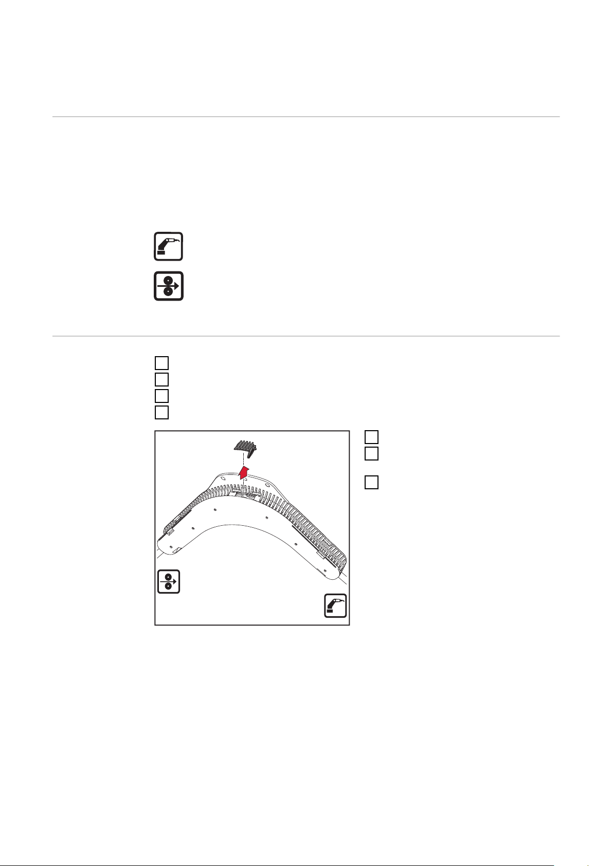
Checking the wire buffer on a PullMig CMT ho-
1
sepack
General remarks To enable the wire buffer’s output signals to be tested in conjunction with a Pull-
Mig CMT hosepack, the wire buffer’s control line must be changed.
IMPORTANT! The wire buffer control line, item no. 43,0004,2803, is not included
in the scope of supply of the wire buffer test box.
Symbols used
Torch side
Feed side
Preparations
Turn power source mains switch to the „O“ position
1
Disconnect the power source from the mains
2
Feed the wire electrode out of the hosepack
3
Disconnect the welding torch from all other system components
4
Remove cover from the control line
5
Unplug the wire buffer’s existing
6
control line
Temporarily connect the wire buf-
7
fer control line, item no.
43,0004,2803, to the wire buffer
20
Page 21

(2)
(1)
Connect the wire buffer test box to
(3)
(4)
8
the power source or wire-feed unit
using the wire buffer connecting
cable (1) and the torch control
connecting cable (2)
DConnect wire buffer to wire buf-
9
fer test box (3)
Prepare the digital multimeter for
10
measuring DC voltage
EN
Checking the
wire buffer
Connect a digital multimeter to the
11
wire buffer test box (4)
WARNING!
Risk of electric shock, if the power source is ON.
This can result in serious personal injury and damage to property.
During all work: ensure that no welding operation is started,
▶
do not touch the central connection of the power source
▶
21
Page 22

(1)
Wire buffer lever upper stop
(2)
Connect the power source to the
1
mains
Turn the power source mains
2
switch to the „I“ position
Push up the wire buffer lever (1) as
3
far as its upper stop in order to simulate wire buffer full
„Wire buffer full“ set value: 2.34 - 2.46
volts
Push down the wire buffer lever (2)
4
as far as its lower stop in order to
simulate „wire buffer empty“
„Wire buffer empty“ set value: 0.42 -
0.54 volts
Wire buffer lever lower stop
Once the test has been completed,
5
restore the wire buffer to its original state
22
Page 23

Checking error messages
(2)
(1)
Safety
Preparations
WARNING!
Danger from incorrect operation and work that is not carried out properly.
This can result in serious personal injury and damage to property.
All the work and functions described in this document must only be carried
▶
out by technically trained and qualified personnel.
Only qualified technicians, who have attended the appropriate Fronius trai-
▶
ning course, are permitted to commission and operate the device.
Read and understand this document in full.
▶
Read and understand all safety rules and user documentation for this device
▶
and all system components.
WARNING!
Danger due to welding processes starting unintentionally.
This can result in serious personal injury and damage to property.
The following steps should only be carried out when there is no wire being
▶
fed in the welding system.
Turn power source mains switch to the „O“ position
1
Disconnect the power source from the mains
2
Feed the wire electrode out of the hosepack
3
Disconnect the welding torch from all other system components
4
EN
Checking error
messages
In welding systems that have an external welding start-up facility (robot applications) it is possible to trigger welding start-up using the Guntrigger switch on the
wire buffer test box. This enables error messages to be checked easily at the
power source’s indicators. To check error messages, proceed as follows:
Connect the wire buffer test box to
1
the power source or wire-feed unit
using the wire buffer connecting
cable (1) and the torch control
connecting cable (2)
23
Page 24

(3)
Connect wire buffer to wire buffer
2
test box (3)
Connect the power source to the
3
mains
Turn the power source mains
4
switch to the „I“ position
Push up the wire buffer lever as far
5
as its upper stop and hold it in this
position
At the same time, move the Gun-
6
trigger switch to the ON position
The power source indicators
-
should be indicating the error
message Efd I 15.2 wire buffer
full
Push down the wire buffer lever as
7
far as its lower stop and hold it in
this position
At the same time, move the Gun-
8
trigger switch to the ON position
The power source indicators
-
should be indicating the error
message Efd I 15.1 wire buffer
empty
24
Page 25

Circuit diagram
EN
25
Page 26

26
Page 27

EN
27
Page 28

 Loading...