

Page 1

Fronius prints on elemental chlorine free paper (ECF) sourced from certified sustainable forests (FSC).
/ Perfect Charging / Perfect Welding / Solar Energy
WF MOUNTING WALL
Installationsanleitung
DE
Drahtvorschub
Installation instructions
EN
Wire-feed unit
Instructions d'installation
FR
Dévidoir
42,0410,2006 004-23082021
Page 2

Page 3

Allgemeines
4x
1x
1x
4x TX25
M5 x 12 mm
DE
Sicherheit
Bestimmungsgemäße Verwendung
WARNUNG!
Gefahr durch fehlerhaft durchgeführte Arbeiten.
Schwerwiegende Personen- und Sachschäden können die Folge sein.
Alle nachfolgend beschriebenen Arbeiten dürfen nur von geschultem Fachpersonal
▶
ausgeführt werden.
Beachten Sie die Sicherheitsvorschriften in der Bedienungsanleitung der Strom-
▶
quelle.
Die Wandhalterung ist ausschließlich für die Verwendung mit Fronius Drahtförder-Komponenten bestimmt.
Eine andere oder darüber hinausgehende Benutzung gilt als nicht bestimmungsgemäß.
Für hieraus entstehende Schäden haftet der Hersteller nicht.
Zur bestimmungsgemäßen Verwendung gehört auch
- das vollständige Lesen dieser Montageanleitung sowie der Bedienungsanleitungen
der Systemkomponenten
- das Befolgen aller Anweisungen und Sicherheitsvorschriften dieser Montageanleitung
- die Einhaltung der in dieser Montageanleitung angegebenen Montagelage des
Abspul-Drahtvorschubes
- die Einhaltung der Inspektions- und Wartungsarbeiten
Lieferumfang
Erforderliches
Werkzeug
- TX25 Schraubendreher
3
Page 4

WF MOUNTING WALL montieren
1
2
3
4
4x
TX25
M5 x 12 mm
4x *
4x *
3
2
1
1
4
2
3
5
WF MOUNTING
WALL montieren
WICHTIG! Bei der Montage des Abspul-Drahtvorschubes am Schlitten darauf achten,
dass keine elektrisch leitende Verbindung zwischen Metallteilen des Abspul-Drahtvorschubes und Schlitten / Wandhalterung besteht.
Abspul-Drahtvorschub nur wie abgebildet am Schlitten montieren!
1
2
* Schrauben, Dübel und Befestigungsmaterial sind nicht im Lieferumfang der
Wandhalterung enthalten. Je nach Untergrund und Montageart entsprechend
geeignetes Befestigungsmaterial auswählen.
3 4
VORSICHT!
Verletzungsgefahr durch herabfallende Objekte!
Schwerwiegende Personen- und Sachschäden können die Folge sein.
Schlitten mit Abspul-Drahtvorschub mit mindestens 2 Flügelschrauben an der
▶
Wandhalterung fixieren!
Je eine Flügelschraube pro Seite verwenden!
▶
4
Page 5

max.
min.
zulässiger Verstellbereich
Max. Belastung der Wandaufnahme:
15 kg
DE
Max. Montagehöhe:
1,7 m ab Boden-Niveau
5
Page 6

General
4x
1x
1x
4x TX25
M5 x 12 mm
Safety
Danger due to work that has been carried out incorrectly.
This can result in serious injury and damage to property.
▶
▶
Proper use The wall bracket is intended exclusively for use with Fronius wirefeeding components.
Utilisation for any other purpose, or in any other manner, shall be deemed to be not in
accordance with the intended purpose.
The manufacturer shall not be held liable for any damages arising from such usage.
Utilisation in accordance with the intended purpose also comprises
- reading these fitting instructions and the operating instructions of the system com-
- following all the instructions and safety rules in these fitting instructions
- observing the installation position specified in these fitting instructions for the unree-
- performing all stipulated inspection and maintenance work
WARNING!
The following activities must only be carried out by trained and qualified personnel.
Observe the safety rules in the power source operating instructions.
ponents in full
ling wire-feed unit
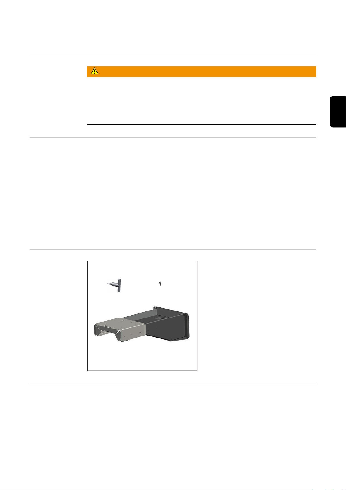
Scope of supply
Tools required - TX25 screwdriver
6
Page 7

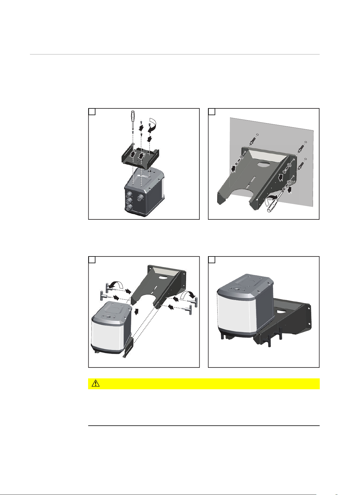
Fitting the WF MOUNTING WALL
1
2
3
4
4x
TX25
M5 x 12 mm
4x *
4x *
3
2
1
1
4
2
3
5
Fitting the WF
MOUNTING
WALL
IMPORTANT! When fitting the unreeling wire-feed unit to the cradle, ensure that there is
no electrically conductive connection between the metal parts of the unreeling wire-feed
unit and the cradle / wall bracket.
Always fit the unreeling wire-feed unit to the cradle as shown.
1
2
* Screws, wall plugs and fixings are not part of the scope of supply of the wall bra-
cket. Select suitable fixings according to the surface and type of fitting.
EN
3 4
CAUTION!
Risk of injury from falling objects.
This can result in serious injury and damage to property.
Fit the cradle and the unreeling wire-feed unit to the wall bracket using at least 2
▶
wing screws.
Use one wing screw on each side.
▶
7
Page 8
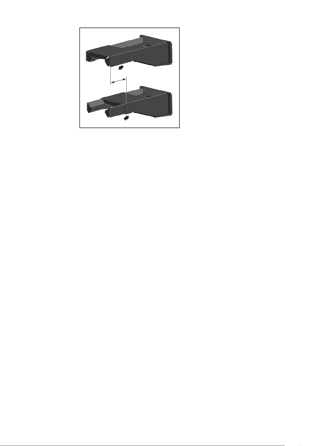
max.
min.
Permitted adjustment range
Max. load capacity of wall bracket:
15 kg
Max. fitting height:
1.7 m above floor level
8
Page 9
Généralités
4x
1x
1x
4x TX25
M5 x 12 mm
Sécurité
Utilisation conforme à la destination
AVERTISSEMENT!
Danger en cas d'erreurs en cours d'opération.
Cela peut entraîner des dommages corporels et matériels graves..
Les opérations décrites ci-après doivent être effectuées exclusivement par du per-
▶
sonnel qualifié et formé !
Respectez les consignes de sécurité figurant dans les instructions de service de la
▶
source de courant.
Le support mural est exclusivement destiné à une utilisation avec des composants
d’amenée de fil Fronius.
Toute autre utilisation est considérée non conforme.
Le fabricant ne saurait être tenu responsable des dommages consécutifs.
Font également partie de l’emploi conforme
- la lecture complète des présentes Instructions de montage ainsi que des Instructions de service des composants périphériques,
- le respect des prescriptions et consignes de sécurité des présentes Instructions de
montage,
- le respect des positions de montage du dévidoir indiquées dans les présentes Instructions de montage,
- le respect des travaux d'inspection et de maintenance,
FR
Contenu de la livraison
Outillage requis - Tournevis TX25
9
Page 10
Installer WF MOUNTING WALL
1
2
3
4
4x
TX25
M5 x 12 mm
4x *
4x *
3
2
1
1
4
2
3
5
Installer WF
MOUNTING
WALL
IMPORTANT ! Lors du montage du dévidoir sur le chariot, veiller à ce qu'aucune liaison
électrique conductrice ne se crée entre les pièces métalliques du dévidoir et le berceau/
support mural.
Monter le dévidoir sur le chariot uniquement comme représenté sur l'illustration !
1
2
* Les vis, chevilles et accessoires de fixation ne sont pas compris dans la livraison
du support mural. Choisir les accessoires de fixation adéquats en fonction du
support et du type de montage.
3 4
ATTENTION!
Risque de blessure en cas de chute d'objets !
Cela peut entraîner des dommages corporels et matériels graves.
Fixer le berceau avec le dévidoir au support mural avec au moins 2 vis à oreilles !
▶
Utiliser une vis à oreilles par côté !
▶
10
Page 11

max.
min.
Plage de réglage tolérée
Charge max. du support mural :
15 kg
Hauteur de montage max. :
1,7 m à partir du niveau du sol
FR
11
Page 12

FRONIUS INTERNATIONAL GMBH
Froniusstraße 1
A-4643 Pettenbach
AUSTRIA
contact@fronius.com
www.fronius.com
Under www.fronius.com/contact you will find the addresses
of all Fronius Sales & Service Partners and locations
 Loading...