

Page 1

Fronius prints on elemental chlorine free paper (ECF) sourced from certified sustainable forests (FSC).
/ Perfect Charging / Perfect Welding / Solar Energy
WF 25i LaserHybrid 6 kW UC
WF 25i LaserHybrid 4 kW UC
SB 360i LaserHybrid
Operating instructions
EN-US
42,0426,0291,EA 006-17122021
Page 2

Page 3

Table of contents
Safety Instructions 6
Explanation of Safety Instructions 6
General 6
Intended Use 7
Environmental Conditions 7
Obligations of the Operating Company 7
Obligations of Personnel 7
Personal Protective Equipment 8
Danger from Toxic Gases and Vapors 8
Danger Posed by Shielding Gas Leak 8
Danger from Flying Sparks 9
Danger from Welding Current 9
Stray Welding Currents 9
EMC Measures 9
Particular Hazard Areas 10
Informal Safety Measures 11
Safety Measures at the Installation Location 11
Safety Measures in Normal Operation 12
Safety Inspection 12
Modifications 13
Spare and Wearing Parts 13
Calibrating Power Sources 13
The CE label 13
Copyright 13
EN-US
General information 15
General 17
General 17
Intended Use 17
Applications 17
Scope of Supply 18
Optional Components 18
Requirements 19
Mechanical Requirements 19
Robot Requirements 19
Ground Connection 19
Alignment 20
System Overview 21
System overview 21
Other LaserHybrid systems 22
Design Variants 24
Operating controls and connections 27
Product description 29
Product description 29
Product description SB 360i LaserHybrid 30
Connection Specifications 32
Connection specifications 32
Compressed air diagram 34
Pressure monitoring in the SplitBox SB 360i LaserHybrid 34
Commissioning 35
General 37
Safety 37
Setup Regulations 37
Grid Connection 37
Setting Up LaserHybrid Welding System 37
Installing the Laser Welding Head on the Robot 39
3
Page 4

Mount Laser Welding Head on the Robot 39
Installing and Connecting SplitBox SB 360i LaserHybrid 40
Mounting the SplitBox SB 360i LaserHybrid on the robot 40
Connecting the SplitBox SB 360i LaserHybrid 42
Connecting the CrossJet and Additional Extraction 45
Connecting the CrossJet and Additional Extraction 45
Connecting/Changing the Wirefeeding Hose on the Laser Welding Head 46
Connecting/Changing the Wirefeeding Hose on the Laser Welding Head 46
Installing/Changing Wirefeed Rollers 47
Preparation 47
Installing/Replacing the Wirefeed Rollers 47
Final Tasks 48
Connecting the Laser Optics 49
Connecting the Laser Optics 49
Preparing Welding Torch 52
Equip Welding Torch 52
Place LaserHybrid hosepack on the robot 54
Placing the hosepack on the robot 54
Threading the Wire Electrode 56
Threading the Wire Electrode 56
Setting up Laser Welding Head 58
Stick Out 58
Adjustable axes 58
Adjustment device on the laser welding head 58
Adjusting the x axis 59
Adjusting the y axis 60
Set the radial airflow 61
Requirements 61
Setting the radial airflow 61
Creating Reference Program 64
Safety 64
General 64
Create a Reference Program 64
Signal Sequence for LaserHybrid Welding 66
Safety 66
Signal Sequence for LaserHybrid Welding 66
Measures before Starting Welding 68
Measures before Starting Welding 68
Operation Recommendations for LaserHybrid Welding System 69
Recommendations for the operation of a LaserHybrid welding system 69
Specifications for the compressed air supply 69
Maintenance 71
Replacing the Welding Torch and Welding Torch Wearing Parts 73
Safety 73
Welding Torch Spare Parts 73
Replacing the Welding Torch 73
Replacing welding torch wearing parts 74
Replace the spatter guard plate 76
Removing the Spatter Guard Plate 76
Mounting the Spatter Guard Plate 76
Replace the LaserHybrid UC hosepack 77
Removing the LaserHybrid UC Hosepack 77
Connect the LaserHybrid UC Hosepack 79
Replacing the Laser Optics 82
Safety 82
Disconnecting the fiber optic cable from the laser optics 82
Removing the Laser Optics 83
Assembly Positions for Installing the Laser Optics 86
Installing the laser optics 86
Checking Position of the Wire Electrode in relation to the Laser Focus 90
Safety 90
4
Page 5

General 90
Checking Position of the Wire Electrode in relation to the Laser Focus 90
Example: Use of the Reference Program after Welding Torch Replacement 90
Measures to Reduce Contamination of the Optics 92
Measures to Reduce Contamination of the Optics 92
Appendix 95
Technical data 97
Laser welding head WF 25i LaserHybrid UC 97
LaserHybrid Hosepack MHP 360i LH-UC 97
SB 360i LH 98
EN-US
5
Page 6

Safety Instructions
Explanation of
Safety Instructions
DANGER!
Indicates an immediate danger.
Death or serious injury may result if appropriate precautions are not taken.
▶
WARNING!
Indicates a possibly dangerous situation.
Death or serious injury may result if appropriate precautions are not taken.
▶
CAUTION!
Indicates a situation where damage or injury could occur.
Minor injury or damage to property may result if appropriate precautions are not
▶
taken.
NOTE!
Indicates the possibility of flawed results and damage to the equipment.
General The LaserHybrid head has been manufactured using state-of-the-art technology and ac-
cording to recognized safety standards. If used incorrectly or misused, however, it can
cause
- injury or death to the operator or a third party,
- damage to the LaserHybrid head and other material assets belonging to the operating company,
- inefficient operation of the LaserHybrid head.
All persons involved in the commissioning, operation, maintenance, and servicing of the
LaserHybrid head must
- be suitably qualified,
- have knowledge of welding and
- have read and implemented carefully these Operating Instructions and the OI for the
following system components:
Laser
Laser optics
Power source and associated wirefeeder
Robot and its controller
The Operating Instructions must always be at hand wherever the LaserHybrid head is
being used. In addition to the Operating Instructions, all applicable local rules and regulations regarding accident prevention and environmental protection must also be followed.
All safety instructions and warning signs on the LaserHybrid head itself must:
- be kept in a legible state
- not be damaged/marked
- not be removed
- not be covered, pasted, or painted over.
For the location of the safety and danger notices on the LaserHybrid head, refer to the
section headed "General" in the Operating Instructions for the LaserHybrid head.
Before switching it on, resolve any faults that could compromise safety.
6
Page 7

Your personal safety is at stake!
Intended Use The LaserHybrid head is to be used exclusively for its intended purpose.
The LaserHybrid head is intended exclusively for LaserHybrid welding of aluminum, CrNi
and steel materials.
Any other use does not constitute proper use.
The manufacturer is not responsible for any damage resulting from improper use.
Proper use also means:
- Completely reading and obeying all instructions in the Operating Instructions
- Completely reading and obeying all safety instructions and danger notices
- Carrying out all the specified inspection and servicing work.
Never use the LaserHybrid head or the power source to thaw pipes.
The LaserHybrid head is designed for operation in industry and business. The manufacturer shall not be liable for any damage resulting from use in a living area.
The manufacturer shall not be liable for faulty or incorrect work results either.
EN-US
Environmental
Conditions
Obligations of the
Operating Company
Operation or storage of the LaserHybrid head outside the stipulated area will be deemed
as not in accordance with the intended purpose. The manufacturer is not responsible for
any damage resulting from improper use.
Temperature range of the ambient air:
- During operation: -10°C to +40°C (14°F to 104°F)
- During transport and storage: -25°C to +55°C (-13°F to 131°F)
Relative humidity:
- Up to 50% at 40°C (104°F)
- Up to 90% at 20°C (68°F)
Ambient air: free of dust, acids, corrosive gases or substances, etc.
Altitude above sea level: up to 2000 m (6561 ft. 8.16 in.)
The operating company must only allow persons to work with the LaserHybrid head if
they
- are familiar with the basic occupational safety and accident prevention regulations
and are trained in handling the LaserHybrid head
- have read and understood these Operating Instructions, especially the section
"Safety Rules," and have confirmed this with their signature
- are trained according to the requirements for the work results.
The safety-conscious work of the personnel must be checked regularly.
Obligations of
Personnel
All persons who are assigned to work with the LaserHybrid head must do the following
before beginning work:
- Follow the basic regulations for occupational safety and accident prevention
- Read these Operating Instructions, especially the section "Safety Rules," and confirm that they have understood and will follow them by signing
Before leaving the workplace, ensure that no personal injury or property damage can occur in one's absence.
7
Page 8

Personal Protective Equipment
Please take the following precautions for your own personal safety:
Persons present in the sealed cell for the LaserHybrid process must
- wear rigid, wet-insulating footwear
- protect hands with appropriate gloves (featuring electrical insulation and thermal
protection)
- protect their eyes from laser beams by wearing regulation-compliant safety glasses
for lasers. To protect their face and eyes against UV beams, further protection in the
form of a protective shield with regulation-compliant filter insert for laser protection
class 4 must also be used in front of the safety glasses for lasers and the person's
face. Do not look into the laser beam, even with a regulation-compliant filter insert
for laser protection class 4.
- Only wear suitable (flame-resistant) clothing
- Wear hearing protection designed for crossjet noise (120 dbA)
If there are persons present in the sealed cell for the LaserHybrid process,
- inform them of all the dangers that may be posed during operation (e.g. potential accumulation of gases hazardous to health, risk of asphyxiation due to lack of oxygen
in the breathable air, hazards posed by laser light, etc.)
- provide protective equipment
- construct protective walls or install protective curtains.
Danger from Toxic Gases and Vapors
The fumes produced during welding contain toxic gases and vapors.
Welding fumes contain substances that may cause birth defects and cancer in some circumstances.
Keep your head out of the welding fumes and gases.
Take the following precautionary measures for fumes and harmful gases:
- Do not breathe them in.
- Extract them from the work area using appropriate equipment.
Ensure that there is sufficient fresh air.
Use breathing apparatus with air supply if there is insufficient ventilation.
When no welding is taking place, close the valve of the shielding gas cylinder or the main
gas supply.
If there is uncertainty as to whether the extraction capacity is sufficient, compare the
measured toxic emission values against the permissible limit values.
The following components are factors that determine how toxic the welding fumes are:
- The metals used for the workpiece
- Electrodes
- Coatings
- Cleaning agents, degreasers, and the like
Danger Posed by
Shielding Gas
Leak
8
Consult the corresponding material safety data sheets and manufacturer's instructions
for the components listed above.
Keep flammable vapors (such as solvent vapors) out of the laser and arc radiation range.
Risk of asphyxiation due to uncontrolled shielding gas leak
Shielding gas is colorless and odorless and may suppress the oxygen in the ambient air
in the event of leakage.
Page 9

- Ensure there is a sufficient supply of fresh air with a ventilation flow rate of at least
20 m³ per hour.
- Please observe the safety and maintenance information for the shielding gas cylinder or the main gas supply.
- When no welding is taking place, close the valve of the shielding gas cylinder or the
main gas supply.
- Always check the shielding gas cylinder or main gas supply for uncontrolled gas
leakage before each start-up.
EN-US
Danger from Flying Sparks
Danger from
Welding Current
Flying sparks can cause fires and explosions.
Never undertake welding near flammable materials.
Flammable materials must be kept at least 11 meters (35 ft.) from the LaserHybrid welding process or protected with a certified cover.
Keep suitable, tested fire extinguishers on hand.
Sparks and pieces of hot metal may also get into surrounding areas through small cracks
and openings. Take appropriate measures to ensure that there is no risk of injury or fire.
Do not undertake welding in areas at risk of fire and explosion, or on sealed tanks,
drums, or pipes if these have not been prepared in accordance with corresponding national and international standards.
Do not undertake welding on containers in which gases, fuels, mineral oils, and the like
are/were stored. Residues pose a risk of explosion.
An electric shock can be fatal. Every electric shock poses a risk of death.
All welding power-leads must be secured, undamaged, and insulated. Replace loose
connections and scorched cables immediately.
Stray Welding
Currents
EMC Measures WARNING! Electromagnetic field! Electromagnetic fields may cause health problems
If the following instructions are not observed, stray welding currents may occur, which
can result in the destruction of ground conductors, the power source used, the LaserHybrid head, and other electrical equipment.
Ensure that the workpiece terminal is securely connected to the workpiece. If the floor is
electrically conductive, set up the power source so that it is insulated wherever possible.
that are not yet known.
The operator is responsible for ensuring that there is no electromagnetic interference
with electrical and electronic equipment.
If electromagnetic interference is discovered, the operator is obliged to take action to rectify the situation.
Check and evaluate possible problems and the interference immunity of equipment in
the vicinity according to national and international regulations:
- Safety devices
- Grid power lines, signal lines, and data transfer lines
- EMC and telecommunications equipment
- Devices for measuring and calibrating
- The health of persons close by, e.g., those with pacemakers and hearing aids
9
Page 10

Persons with pacemakers must seek advice from their doctor before staying in the immediate vicinity of where the welding work is taking place.
Supporting measures to avoid EMC problems:
a) Grid power supply
- If electromagnetic interference occurs despite a grid connection that complies
with regulations, take additional measures (e.g., use a suitable grid filter).
b) Welding power-leads
- Keep them as short as possible
- Route them close together (also to avoid EMC problems)
- Route them far from other lines
c) Equipotential bonding
d) Workpiece grounding
- If necessary, establish grounding using suitable capacitors
e) Shield, if necessary
- Shield other devices in the vicinity
- Shield the entire welding installation
Particular Hazard
Areas
Laser beam poses a risk of injury to the eyes. In addition to using the protective shield
with a regulation-compliant UV filter insert, eyes should be protected from laser beams
using regulation-compliant safety glasses for lasers. It must still be ensured, however,
that no one can accidentally look into the laser beam.
If the workpiece surface is especially bright or highly reflective, reflected laser-scattering
radiation poses a further risk. Take suitable precautions so that persons present have adequate protection from laser-scattering radiation also.
Keep hands, hair, loose clothing, and tools away from moving parts, such as:
- Ventilators
- Gear wheels
- Rollers
- Shafts
- Wirespools and welding wires
Do not insert body parts into rotating gear wheels on the wire drive or into rotating drive
parts.
Covers and side parts must only be opened/removed during maintenance and repair
work.
During operation:
- Ensure that all covers are closed and all side parts have been mounted properly.
- Keep all covers and side parts closed.
10
Welding wire from the welding torch poses a high risk of injury (cuts to the hand, injuries
to the face and eyes, etc.).
For this reason, always hold the welding torch away from your body (devices with
wirefeeder) and wear suitable protective goggles.
Do not touch workpieces during or after welding – risk of burns.
Slag may fly off from workpieces that are cooling down. For this reason, be sure to wear
regulation-compliant protective equipment and ensure that other people are sufficiently
protected even when reworking workpieces.
Leave the welding torch and other parts with a high operating temperature to cool before
working on them.
Page 11

Special regulations apply in areas where there is a risk of fire or explosion
– observe relevant national and international regulations.
Power sources for work in spaces where electrical hazards pose a greater risk (e.g. the
boiler room) must be marked with a (Safety) sign. The power source should not be located in these types of spaces, however.
Risk of scalding due to coolant leakage. Before disconnecting connections for the
coolant supply hose or return connection, switch off the cooling unit.
When handling coolants, observe the specifications on the safety data sheet. The
coolant safety data sheet is available from your service center or from the manufacturer's
homepage.
Only use suitable load-carrying equipment from the manufacturer for transporting
devices by crane.
- Attach chains or ropes to all designated suspension points on suitable load-carrying
equipment.
- Chains or ropes must be as close to perpendicular as possible.
- Remove the gas cylinder and wirefeeder (MIG/MAG and TIG devices).
Always use a suitable wirefeeder hoisting attachment with insulation on the crane for
hoisting the wirefeeder (MIG/MAG and TIG devices).
If the device is fitted with a carrier belt or handle, this should be used exclusively for
transportation by hand. The carrier belt is not suitable for transportation by crane, counterbalanced lift truck or other mechanical chain hoists.
All lifting equipment (belts, straps, chains, etc.) used in connection with the device or its
components must be checked regularly (e.g., for mechanical damage, corrosion, or
changes due to other environmental influences).
The test interval and scope must, as a minimum, comply with the respective valid national standards and guidelines.
EN-US
Informal Safety
Measures
Safety Measures
at the Installation
Location
There is a risk of colorless, odorless shielding gas escaping without notice if an adapter
is used for the shielding gas connection. Use suitable Teflon tape to seal the thread of
the shielding gas connection adapter on the device side before installation.
The Operating Instructions must always be at hand wherever the LaserHybrid head is
being used.
In addition to the Operating Instructions, all applicable local rules and regulations regarding accident prevention and environmental protection must also be made available and
be followed.
All safety and danger notices on the LaserHybrid head must be kept in a legible state.
The cell for the LaserHybrid welding process must meet the following requirements:
- be light-proof in relation to surrounding rooms
- is shielded with at least 1 mm steel plate and/or approved laser protective glass to
protect against UV and laser beams
- The laser welding process and the arc welding process must be stopped automatically and immediately as soon as the cell is opened.
A toppling device can be deadly! Set up the device securely on an even, solid surface
- A tilt angle of no more than 10° is permitted
Special regulations apply in areas at risk of fire or explosion
- Follow the appropriate national and international regulations.
11
Page 12

Use instructions and checks within the company to ensure that the vicinity of the workplace is always clean and organized.
Only set up and operate the device in accordance with the degree of protection shown
on the rating plate.
When setting up the device, ensure an all-round clearance of 0.5 m (1 ft. 7.69 in.) so that
the cooling air can enter and leave unhindered.
Take care to ensure that the applicable national and regional guidelines and accident
prevention regulations are observed when transporting the device, especially guidelines
concerning hazards during transport and shipment.
Before transporting the device, always completely drain the coolant and dismantle the
following components:
- Wirefeeder
- Wirespool
- Shielding gas cylinder
It is essential to conduct a visual inspection of the device to check for damage after it has
been transported but before it is commissioned. Have any damage repaired by trained
service technicians before commissioning the device.
Safety Measures
in Normal Operation
Safety Inspection The operator is required to have the LaserHybrid head tested by an electrician after
Only operate the LaserHybrid head if all protective and safety devices are fully functional. If the safety devices are not fully functional, there is a risk of
- injury or death to the operator or a third party,
- damage to the device and other material assets belonging to the operating company,
- inefficient operation of the device.
Safety devices that are not fully functional must be repaired before the device is switched
on.
Never bypass or disable safety devices.
Before conditioning the LaserHybrid head, ensure that no one can be put in danger.
The LaserHybrid head must be examined at least once a week for externally detectable
damage and functionality of the safety devices.
every alteration, installation or modification, and all repairs and maintenance, and at
least every 12 months, to ensure that it is in its correct state.
Regulation Title
12
IEC (EN) 60 974-1 Equipment for Arc Welding, Part 1: Welding Current Sources
BGV A2, Section 5 Electrical Plants and Equipment
BGV D1, Sections 33 /49Welding, Cutting and Related Work Methods
VDE 0701-1 Repairing, Modifying and Testing Electrical Devices;
General Requirements
VDE 0702-1 Repeating Tests on Electrical Devices
Page 13

Modifications Do not carry out any alterations, installations, or modifications to the LaserHybrid head
without first obtaining the manufacturer’s permission.
Parts that are not in perfect condition must be replaced immediately.
EN-US
Spare and Wearing Parts
Calibrating Power
Sources
The CE label The LaserHybrid head meets the basic requirements of the Low Voltage and Electro-
Copyright Copyright of these Operating Instructions remains with the manufacturer.
Use only original spare and wearing parts (also applies to standard parts).
It is impossible to guarantee that externally procured parts are designed and manufactured to meet the demands made on them, or that they satisfy safety requirements.
When ordering, specify the exact name and part number according to the Spare Parts
List as well as the serial number of your device.
Regular calibration of power sources is required in accordance with international standards. The manufacturer recommends a calibration interval of 12 months. Please contact
your service center if you require further details.
magnetic Compatibility Directives and therefore has CE sign.
Text and illustrations were accurate at the time of printing. Fronius reserves the right to
make changes. The contents of the Operating Instructions shall not provide the basis for
any claims whatsoever on the part of the purchaser. If you have any suggestions for improvement, or can point out any mistakes that you have found in the Operating Instructions, we will be most grateful for your comments.
13
Page 14

14
Page 15

General information
15
Page 16

16
Page 17

General
EN-US
General
The laser welding head WF 25i LaserHybrid UC is ideal for components with limited accessibility and is available in two
versions:
- WF 25i LaserHybrid 6 kW UC
Focal length of the laser optics =
300 mm
- WF 25i LaserHybrid 4 kW UC
Focal length of the laser optics =
200 mm
The WF 25i LaserHybrid UC is referred to
as the laser welding head for the rest of
these Operating Instructions.
Laser welding head WF 25i LaserHybrid 6 kW UC
with optional camera
Additional benefits of the laser welding head:
- high welding speed and great cost-effectiveness
- high process stability combined with a low level of rejects and reworking effort
- high quality weld seam
- low heat input, reduced distortion
- high availability of the welding system, high service life of the wearing parts
- flexible use
- high gap tolerance
- adaptation for fiber, disk, and diode laser possible.
Intended Use The WF 25i LaserHybrid UC is intended exclusively for automatic MIG/MAG welding in
combination with Fronius system components.
Any other use does not constitute proper use.
The manufacturer is not responsible for any damage resulting from improper use.
Proper use also means:
- following all the instructions from the Operating Instructions for the individual components
- carrying out all the specified inspection and servicing work.
Applications The laser welding head is primarily used for MIG laser and MAG laser applications:
- in axle and bodywork production in the automotive industry for plate thicknesses of
1–4 mm
- in pipeline construction for plate thicknesses of 6–16 mm for the root pass
- in tank and boiler manufacturing.
17
Page 18

Scope of Supply - 1 laser welding head WF 25i LaserHybrid UC (complete)
- 1 LaserHybrid UC hosepack
- 1 metal gauge to set the focal spot
- 1 flat spanner, size 8/10 mm
- 1 slotted screwdriver, 2.5 mm
- 1 Allen key, 2.5 mm
- 1 ballpoint Allen wrench, size 3 mm
- 1 ballpoint Allen wrench, size 4 mm
- 1 drive wheel spanner
- 1 stick out gauge
- 1 PushIn coupling connection
- 1 hose, 4x750 mm
- 1 flow volume meter up to 25 l/min
- 1 Operating Instructions
- Wirefeed accessories, depending on configuration
Optional Components
The following components are optional for the laser welding head WF 25i LaserHybrid
UC:
- Focus monitor
- Various laser beam sources
- Temperature sensor
- CrashBox
- Additional data line 3 x 0.5 mm²
18
Page 19

Requirements
-
-
EN-US
Mechanical Requirements
Robot Requirements
Ground Connection
The following mechanical requirements must be met in order to ensure a stable and repeatable LaserHybrid process:
- Accurate welding torch guidance for robots or single-purpose machines (e.g. longitudinal chassis)
- Precise weld seam preparation
- Low component tolerances
- Precise and very fast weld seam management systems with little deviation
The laser welding head weighs approx. 7 kg. The optics weigh approx. an additional
2 kg. A mass of approx. 9 kg must be allowed for if the laser welding head is fully
equipped with optics and hosepack.
Therefore it must be possible for the robot axles to move a mass of 8 kg safely with the
accelerations specified.
The maximum resulting robot axle acceleration must not exceed 3 G (corresponds to approx. 30 m/s²).
Grounding cable with bifilar winding
Grounding cable coiled
19
Page 20

Alignment
y
5°
Example: Work angle 5°, leading
CAUTION!
Danger of serious damage by laser radiation reflected directly into the laser
optics!
This can cause serious damage to the
fiber optic.
Always avoid 90° angles to the work-
▶
piece surface when aligning the LaserHybrid head.
20
Page 21

System Overview
(1)
(2)
(3)
(4)
(5)
(6)
(7)
(11)
(10)
(8)
(9)
(12)
System overview LaserHybrid system with SplitBox SB 360i LaserHybrid installed on the robot
(1) Welding wire drum *
(2) Unwinding wirefeeder:
WF 25i REEL 4R
+ OPT/i WF wire straightener (4,100,880,CK)
+ WF MOUNTING Drum
(3) Control line for unwinding wirefeeder
(4) Remote control
(5) Power source TPS 500i
+ robot interface **
+ cooling unit CU 1400i Pro MC or CU 2000i MC Single
+ upright bracket (screwed on)
(6) Wirefeeding hose
(7) Interconnecting hosepack
(8) Robot
(9) SplitBox SB 360i LaserHybrid
(10) LaserHybrid hosepack
(11) WF 25i LaserHybrid UC
(12) LaserHybrid cleaning station
EN-US
* As an alternative to the welding wire drum, the wirefeeding can also be carried
out via wirespools.
The following components are required for this purpose:
Unwinding wirefeeder WF 25i REEL 4R
+ OPT/i WF reel carriage D300
** for example: RI FB Inside/i or RI FB Pro/i
21
Page 22

Other LaserHy-
(1)
(2)
(3)
(4)
(5)
(6)
(7)
(11)
(10)
(8)
(9)
(12)
brid systems
LaserHybrid system with SplitBox SB 360i LaserHybrid installed on the wall
(3) Wirefeeding hose
(4) Interconnecting hosepack
(5) Robot
(6) SplitBox SB 360i LaserHybrid
(7) LaserHybrid hosepack
(8) WF 25i LaserHybrid UC
(9) LaserHybrid cleaning station
(10) Welding wire drum
(11) Unwinding wirefeeder:
WF 25i REEL 4R
+ OPT/i WF wire straightener (4,100,880,CK)
+ WF MOUNTING Wall
(12) Control line for unwinding wirefeeder
(13) Remote control
(14) Power source TPS 500i
+ robot interface
+ cooling unit CU 1400i Pro MC or CU 2000i MC Single
+ upright bracket (screwed on)
22
Page 23

LaserHybrid system with SplitBox SB 360i LaserHybrid installed on the power
(5)
(6)
(2)
(1)
(3)
(8)
(10)
(7)
(9)
(4)
(11)
source
(1) Remote control
(2) Control line for unwinding wirefeeder
(3) Power source TPS 500i
+ robot interface
+ cooling unit CU 1400i Pro MC or CU 2000i MC Single
+ upright bracket (screwed on)
+ interconnecting hosepack
(4) SplitBox SB 360i LaserHybrid
(5) Wirespool D300
(6) Unwinding wirefeeder:
WF 25i REEL 4R
+ OPT/i WF Reel carriage D300
(7) LaserHybrid hosepack
(8) Wirefeeding hose
(9) Robot
(10) WF 25i LaserHybrid 6 kW UC
(11) LaserHybrid cleaning station
EN-US
23
Page 24

Design Variants
Power source is in the welding cell (I)
- TPS 500i – power source
- HP 95i CON W/1.2 m/95 mm² – interconnecting hosepack
- SB 360i LaserHybrid – SplitBox, mounted on the power source
- MHP 300i LH W/7.5 m – LaserHybrid hosepack
- Welding wire drum
- WF 25i REEL 4R – unwinding wirefeeder
- WF MOUNTING Drum
- Wirefeeding hose L=10 m
- Laser welding head
Application:
The robot only makes slight compensatory movements.
Robot axles seven and eight carry out the majority of the welding feed movement.
Example:
Circumferential weld on boilers, axles, etc.
Power source is in the welding cell (II)
- TPS 500i – power source
- HP 95i CON W/1.2 m/95 mm² – interconnecting hosepack
- SB 360i LaserHybrid – SplitBox, mounted on the power source
- MHP 300i LH W/7.5 m – LaserHybrid hosepack
- Wirespool
- WF 25i REEL 4R – unwinding wirefeeder
- WF reel carriage D300
- Wirefeeding hose L=10 m
- Laser welding head
Application:
Only for test systems (wirespool is not used in series production)
Power source is not in the welding cell (I)
- TPS 500i – power source
- HP 95i CON W/10 m/95 mm² – interconnecting hosepack
- SB 360i LaserHybrid – SplitBox, mounted on the robot or on the wall
- MHP 300i LH W/4.2 m – LaserHybrid hosepack
- Welding wire drum
- WF 25i REEL 4R – unwinding wirefeeder
- WF MOUNTING Drum
- Wirefeeding hose L=20 m
- Laser welding head
Application:
Robot axles 1–6 carry out the welding feed movement.
Example:
Longitudinal seam on boilers, battery trays, etc.
24
Page 25

Power source is not in the welding cell (II)
- TPS 500i – power source
- HP 95i CON W/10 m/95 mm² – interconnecting hosepack
- SB 360i LaserHybrid – SplitBox, wall mounting
- MHP 300i LH W/7.5 m – LaserHybrid hosepack
- Welding wire drum
- WF 25i REEL 4R – unwinding wirefeeder
- WF MOUNTING Drum
- Wirefeeding hose L=20 m
- Laser welding head
Application:
Robot axles 1–6 carry out the welding feed movement.
Example:
Longitudinal seam on boilers, battery trays, etc.
Power source is on a gantry and moves at the same time
- TPS 500i – power source
- HP 95i CON W/10 m/95 mm² – interconnecting hosepack
- SB 360i LaserHybrid – SplitBox, mounted on the gantry
- MHP 300i LH W/4.2 m or 7.5 m – LaserHybrid hosepack
- Welding wire drum
- WF 25i REEL 4R – unwinding wirefeeder
- WF MOUNTING Drum
- Wirefeeding hose L=20 m
- Laser welding head
EN-US
Application:
Robot axles 1–8 carry out the welding feed movement.
Example:
Longitudinal seam in rail vehicle manufacturing, etc.
25
Page 26

26
Page 27

Operating controls and connections
27
Page 28

28
Page 29

Product description
(2)
(1)
(3)
(5)
(6)
(7)
(8)
(10)
(17)
(16)
(15)
(14)
(11)
(12)
(13)
(4)
(3a)
(9)
Product description
EN-US
Item Name
(1) CrossJet exhaust air connection
(2) Protective cover/fiber optic cable connection
(3) Additional extraction tube
(3a)
Optional additional extraction tube
with matching spatter guard plate
Depending on the configuration, one of the two extraction tubes is fitted on deliv-
ery.
(4) Camera (option)
(5) Laser optics
(6) Radial air flow
(7) Gas nozzle
29
Page 30

(8) LaserHybrid welding torch
(a)
(b)
(c)
(1)
(2)
(3)
(4)
(5)
(6)
(7)
(8)
(14)
(13)
(12)
(11)
(9)
(8)
(10)
(9) Adjustment device
(10) Wirefeeder roller cover
(11) Motor cover
(12) Control box
(13) Robot connection bracket
The controls are located on the opposite robot connection bracket:
a) Wire-return button
b) Wire-threading button
c) Gas-test button
Product description SB 360i
LaserHybrid
(14) Robot support
(15) CrashBox (option)
(16) Laser optics water cooling connection
(17) LaserHybrid UC hosepack
30
Back
Item Name
(1) (+) Current socket with fine thread
(2) Shielding gas connection socket
For connecting the power cable from the interconnecting hosepack
Front
Page 31

(3) SpeedNet connection
For connecting the SpeedNet cable from the interconnecting hosepack
(4) SpeedNet connection
For connecting system add-ons, such as remote control
(5) Gas purging connection
(6) Welding torch cooling connection - coolant return (red)
For connecting the coolant return hose from the interconnecting hosepack
(7) Welding torch cooling connection - coolant supply (blue)
For connecting the coolant supply hose from the interconnecting hosepack
(8) SplitBox SB 360i LaserHybrid mount
(9) Welding torch connection (FSC)
For connecting the LaserHybrid hosepack
(10) Crossjet OUT connection
(11) Crossjet OUT connection
(12) Crossjet IN connection
(13) Interconnecting hosepack (to the power source)
Originally not included in the SB 300i LaserHybrid; the interconnecting hosepack
is used during the installation into the SB 300i LaserHybrid.
EN-US
(14) Welding torch cooling connecting plug
For connecting the welding torch cooling to the LaserHybrid hosepack
31
Page 32

Connection Specifications
(1)
(2)
(3)
(4)
(5)
(6)
(7)
Connection specifications
Item Name
(1) Fiber optic cable for laser
Bending radius > 200 mm
IMPORTANT! For the fiber optic cable, only use fibers </= 0.3 mm! Larger fibers
may impair the welding result and lead to damage to the laser welding head.
(2) Additional extraction connection
For connecting a hose as per the following data:
- Inner diameter Di = 41 mm
- max. length = 10 m
- Recommended extraction capacity = min. 60 m³/h
(3) CrossJet exhaust air connection
For connecting a hose as per the following data:
- Inner diameter Di = 50 mm
32
(4) CrossJet compressed air connection
(from the LaserHybrid interconnecting hosepack)
Page 33

- Operate at 6 bar and a volumetric flow of 60 m³/h
- CrossJet exhaust air 170 m³/h
(5) Laser optics water cooling connections
(from the LaserHybrid interconnecting hosepack)
(6) External wirefeeding hose (Fronius)
(7) LaserHybrid interconnecting hosepack (Fronius)
Hosepack incl. compressed air for CrossJet and radial air flow, laser optics water
cooling, and media coupling
EN-US
33
Page 34

Compressed air
WF 25i LaserHybrid 6 kW UCSB 360i LaserHybrid
MHP LH
(1)
(2)
(3)
(4)
(5)
(6)
(6)
(7)
(4)
(5)
*
diagram
MHP LH = LaserHybrid hosepack
Item Name
(1) Compressed air supply line
(min. 4.5 bar)
Pressure monitoring in the SplitBox SB 360i
LaserHybrid
(2) Solenoid valve
(3) Internal pressure measurement
(4) Radial air flow branch
(5) CrossJet air supply line connec-
tion
(6) CrossJet exhaust air
(7) Additional extraction
* Cover hidden
NOTE!
The "VALVE ON" signal for controlling the solenoid valve (2) is transmitted on bit
26 (away from 0).
The pressure is measured after the solenoid valve.
If the pressure falls below 4.5 bar for longer than 2 seconds, then the "Powersource
Ready" bit is withdrawn and the warning code 16835 (laser Crossjet air pressure supply
low) is output.
34
From power source software version 2.4.0:
If the pressure drops below 4.5 bar for longer than 2 seconds, the "Warning-Bit" is set
and the error code 16835 (laser Crossjet air pressure supply low) is output.
The current Crossjet pressure is displayed in the SmartManager (power source website)
under "Actual system data".
Page 35

Commissioning
35
Page 36

36
Page 37

General
EN-US
Safety
Setup Regulations
WARNING!
Work performed incorrectly can cause serious injury and damage to property.
This setting work must only be carried out by trained and qualified personnel.
▶
Observe the safety rules in the OI, in particular the "Safety Inspection" section.
▶
The power sources have been tested according to protection class IP 23. This means:
- Protection against solid foreign bodies larger than Ø 12 mm (0.47 in.)
- Protection against spraywater up to an inclined angle of 60°
The welding system can be set up and operated outdoors in accordance with protection
class IP 23. However, the effects of direct moisture (e.g. from rain) must be avoided.
WARNING!
Toppling or falling devices can be deadly.
Securely set up the devices on a level and stable surface.
▶
The ventilation channel of the power sources is an important safety device. When selecting the setup location, ensure that the cooling air can enter and exit unhindered through
the vents on the front and back. Any electrically conductive dust (e.g. from grinding work)
must not be allowed to be sucked directly into the system.
Grid Connection The device is designed for the grid voltage listed on the rating plate. The fuse protection
required for the grid lead can be found in the "Technical Data" section. If mains cables or
mains plugs are not included with your version of the appliance, attach the appropriate
mains cable or mains plug in accordance with your country's standards.
CAUTION!
An under-dimensioned electrical installation can lead to serious damage.
The grid lead and its fuse protection should be designed to suit the existing power
▶
supply.
The technical data on the rating plate should be followed.
▶
Setting Up LaserHybrid Welding
System
If a power source is connected to the grid during installation, there is a danger of
serious personal injury and property damage.
Please read the “Safety Rules” chapter for the power source in the Operating Instructions before using it for the first time. All preparation steps must only be performed if
▶
▶
WARNING!
the power switch of the power source is set to “O”,
the mains cable has been disconnected from the grid.
37
Page 38

Initial situation:
Robot and robot control are available and ready for operation
Set up welding system:
Mount upright brackets
1
Mount cooling unit on upright bracket
2
Connect power source to cooling unit
3
Set up welding wire drum
4
Mount WF MOUNTING drum on the welding wire drum
5
Set up and connect unwinding wirefeeder
6
Connect power source with robot control
7
Connect remote control
8
Set up laser welding head:
Mount laser welding head on the robot
9
Mount and connect SplitBox SB 360i LaserHybrid
10
Connect CrossJet
11
Connecting/changing the wirefeeding hose on the laser welding head
12
Installing/changing the wirefeed rollers
13
Connect laser optics and additional extraction
14
Equip welding torch
15
Place LaserHybrid hosepack on the robot
16
Thread the wire electrode
17
Other activities before start-up:
Adjust the laser welding head
18
Set the radial airflow
19
Create a reference program
20
Signal sequence for LaserHybrid welding
21
Measures before starting welding
22
Create ground earth connection between the workpiece and power source
23
38
Page 39

Installing the Laser Welding Head on the Robot
1
EN-US
Mount Laser
Welding Head on
the Robot
NOTE!
The laser welding head does not have standard collision protection.
Fronius therefore recommends the use of standard collision protection for robotic applications in order to prevent damage to the laser welding head in the event of a crash.
E.g.:
44,0350,5203
Fronius CrashBox QS 400 (for ABB robot 4600)
1
Mount the laser welding head on the robot
according to the robot manufacturer's specifications.
39
Page 40

Installing and Connecting SplitBox SB 360i Lase-
3
3
3
3
4
rHybrid
Mounting the
SplitBox SB 360i
LaserHybrid on
the robot
Disconnect SplitBox SB 360i LaserHybrid and SplitBox mount
1
Depending on the robot, mount an appropriate support for the SplitBox mount on the
2
robot
IMPORTANT! Observe robot manufacturer's mounting instructions.
Mount SplitBox mount on the support
3
using 4 Allen screws size 6 mm
Tightening torque = 24 Nm
Insert strain-relief device of the inter-
4
connecting hosepack into the opening
and push forwards
40
Page 41

5
7
6
5
Secure strain-relief device of the inter-
8
8
9
10
10
10
1
0
1
0
1
0
5
connecting hosepack using 2 Allen
screws size 4 mm
Open clamps (x2)
6
Insert interconnecting hosepack into
7
the clamps
Close clamps
8
EN-US
Insert SplitBox SB 360i LaserHybrid
9
into the SplitBox mount as per the diagram
Secure SplitBox into the SplitBox
10
mount using 3 TX25 screws from
above and 3 TX25 from below
Tightening torque = 3.5 Nm
41
Page 42
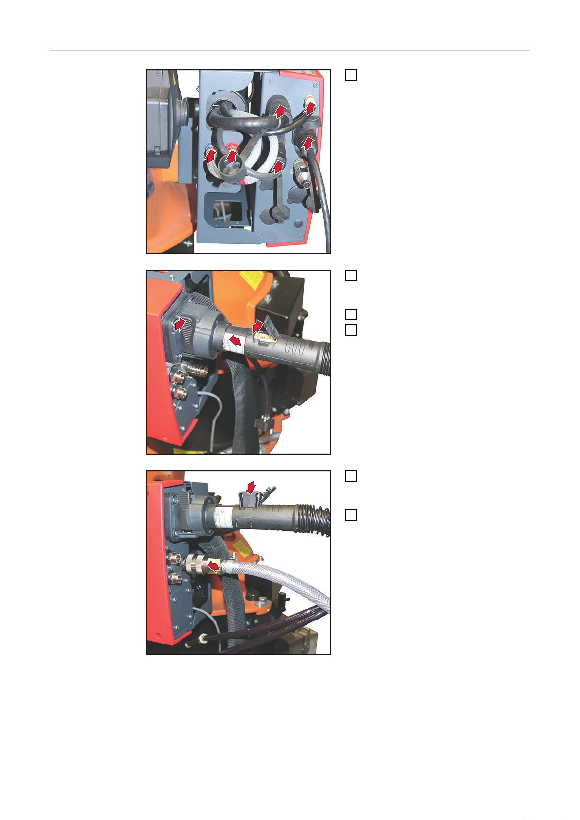
Connecting the
a
*
b
c
d
e
f
3
2
4
6
5
SplitBox SB 360i
LaserHybrid
Connect the interconnecting hosepack
1
to the SplitBox:
a) Power cable
b) Welding torch cooling return (red)
c) Welding torch cooling supply
(blue)
d) Shielding gas
e) SpeedNet (from the interconnect-
ing hosepack)
f) SpeedNet (remote control)
* gas purging connection
Connect the LaserHybrid hosepack to
2
the welding torch connection (Fronius
System Connector)
Close clamping lever
3
Open the cover on the LaserHybrid
4
hosepack
Connect welding torch cooling con-
5
necting plug to the LaserHybrid
hosepack
Connect the CrossJet air inlet
6
42
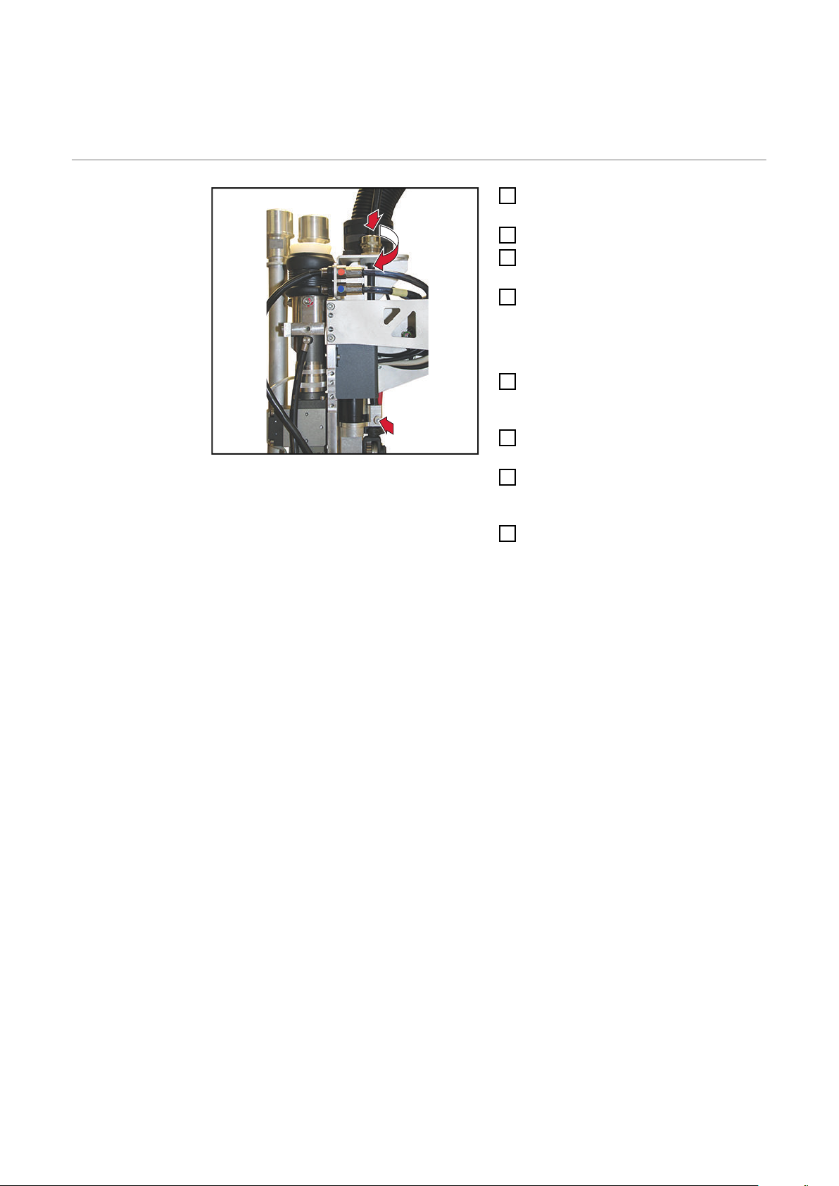
Page 43

7
8
7
Only one CrossJet air outlet hose is avail-
8a
8a
8b
8b
able for applications with the laser welding
head WF 25i LaserHybrid 4/6 kW UC.
IMPORTANT! When connecting the
CrossJet air outlet hose, ensure that the
cutting ring is present!
Connect CrossJet air outlet
7
Secure the hose to the connection
8
socket using hexagonal nut, size
24 mm
tightening torque = 50 Nm
IMPORTANT! When securing the
hexagonal nut to the connection socket,
counter with a 21 mm wrench.
8a
Unscrew the free connection socket
size 21 mm
EN-US
8b
Insert blanking plug
size 17 mm
43
Page 44

9
9
9
9
9
(1)
Connect interconnecting hosepack to the power source
10
Option:
(1) Data line 3 x 0.5 mm²
Connect hoses for optics cooling
(push-in)
blue marking = coolant supply
(e.g. for analyzing additional pressure monitoring)
44
Page 45

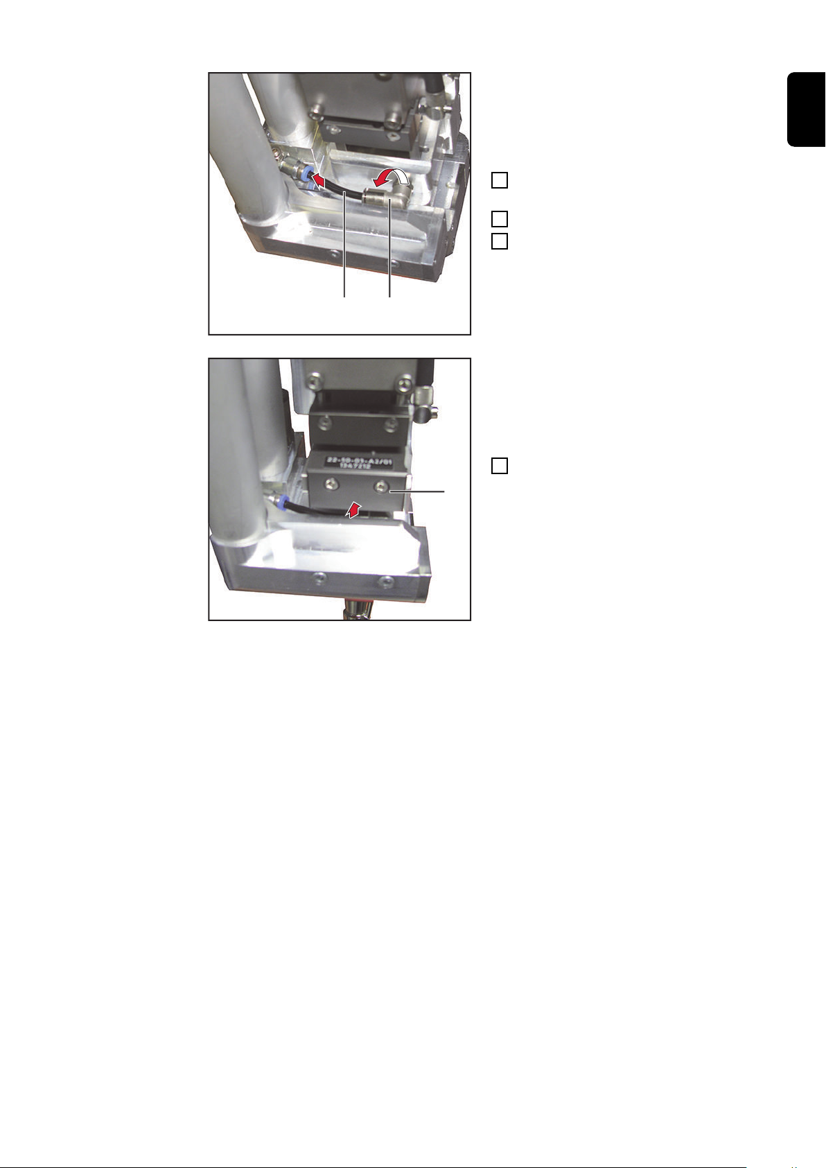
Connecting the CrossJet and Additional Extraction
1
2
1
3
3
4
EN-US
Connecting the
CrossJet and Additional Extraction
Connecting the CrossJet:
With a hose clamp, slide the hose with
1
an inner diameter of 50 mm over the
CrossJet exhaust air connection
Tighten the hose clamp
2
Connect the additional extraction:
With hose clamp, slide the hose with
3
an inner diameter of 40 mm over the
additional extraction connection
Tighten the hose clamp
4
45
Page 46
Connecting/Changing the Wirefeeding Hose on the
2
1
4
Laser Welding Head
Connecting/
Changing the
Wirefeeding Hose
on the Laser
Welding Head
Insert wirefeeding hose into the laser
1
welding head
Press and hold locking button
2
Insert the wirefeeding hose until the
3
locking button is released
Tighten the strain-relief device
4
24 mm
Replacing the Wirefeeding Hose
Unthread the wire electrode from the
1
wirefeeding hose by pushing the wire
return button
Release the strain-relief device
2
24 mm
Push the locking button and simultan-
3
eously disconnect the wirefeeding
hose
Pull out the wirefeeding hose
4
46
Page 47
Installing/Changing Wirefeed Rollers
2
1
1
2
Preparation
Remove two Allen screws
1
size 3 mm
Remove wirefeeder roller cover
2
EN-US
Installing/Replacing the Wirefeed
Rollers
IMPORTANT! The wire electrode must be pulled out in order to change the wirefeed
roller.
Disconnect the wirefeeding hose
1
Swing open the clamping stirrup
2
47
Page 48

4
3
Remove the screw-type shaft
5
6
5
5
1
2
2
3
Remove the wirefeed roller
4
Remove the hexagonal nut, size
5
10 mm – use the drive wheel spanner
included in the scope of supply for the
laser welding head to hold on the
wirefeed roller
Remove the wirefeed roller
6
Final Tasks
Install by performing the steps in the reverse order
NOTE!
When mounting the covers, ensure that
the cables are not trapped, crushed, or
damaged in any other way.
Position the wirefeeder roller cover
1
Mount the wirefeeder roller cover with
2
two Allen screws
size 3 mm
48
Page 49

Connecting the Laser Optics
1
2
3
4
EN-US
Connecting the
Laser Optics
CAUTION!
Risk of damage to the laser welding head due to contamination from above.
Observe the Operating Instructions, specifications, and safety instructions provided
▶
by the laser optics manufacturer
Before connecting, position the laser welding head so that the longitudinal axis of
▶
the laser welding head is outside of the horizontal (> 90°). This means that no dirt
can get into the laser optics from above.
Position the laser welding head so that
1
the longitudinal axis of the laser welding head is outside the horizontal (>
90°)
Clean the connection area and plug of
2
the fiber optic cable using compressed
air
Remove the protective cover from the
3
fiber optic cable connection
Remove the protective cover from the
4
fiber optic cable connector
49
Page 50

c
a
b
b
IMPORTANT! When connecting the fiber
7
7
optic cable, pay attention to the position of
the register pin on the connector!
Connect fiber optic cable:
5
a) Press the button
b) Withdraw the rubber sleeve in the
direction of the optics
c) Connect the fiber optic cable con-
nector
Check whether the rubber sleeve is
6
cleanly sealed all around the fiber optic cable connector
IMPORTANT! The picture opposite
shows an incorrectly positioned rubber
sleeve!
The rubber sleeve shown has a kink in
the area indicated by the arrows, and
therefore it is not fully sealed.
INCORRECTLY positioned rubber sleeve!
The rubber sleeve does not seal fully.
Connect the optics cooling using Allen
7
screw, 2.5 mm
tightening torque = 4 Nm
50
Page 51

8
Position the laser welding head in the vertical line
9
Connect the optics cooling supply
8
(blue marking)
EN-US
51
Page 52

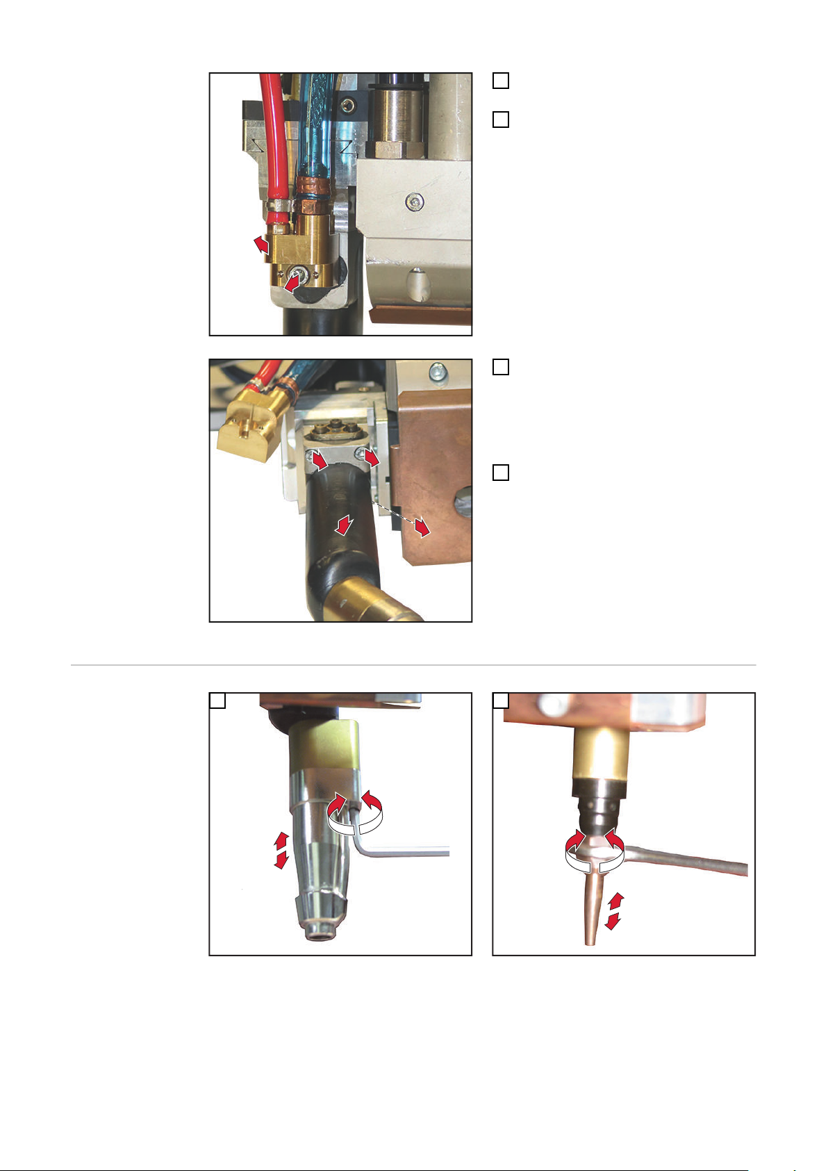
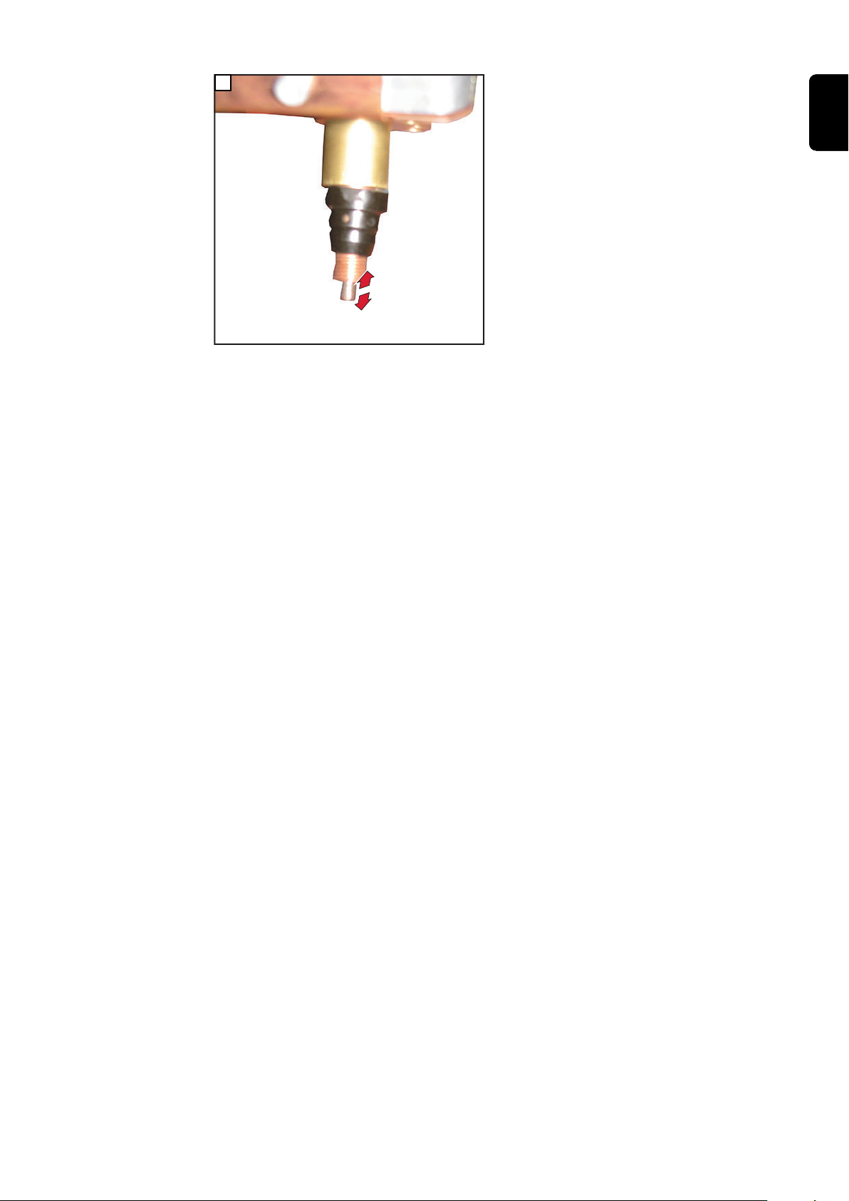
Preparing Welding Torch
2
3
4
5
Equip Welding
Torch
Insert the inner liner into the welding
1
torch from below
Insert inner liner fully into the welding
2
torch using the contact tip
Position union nut via the contact tip
3
Tighten the union nut
4
size 12 mm
tightening torque = 3 Nm
52
Page 53

8
6
7
Apply the gas nozzle
5
Secure the gas nozzle with Allen
6
screw, 4 mm
Fold bracket downwards
7
EN-US
53
Page 54

Place LaserHybrid hosepack on the robot
(1)
(2)
(4)
44,0360,0099
10 x 5 Nm
2,9 Nm
2,9 Nm
8 Nm
27 Nm
(11)
42,1000,0112
44,0350,0254
(11)
(12)
(14)
M
10 /
45
Nm
(3a)
(3)
(4)
(6)
(7)
(8)
(7)
(10)
(5)
(9)
(6)
(11)
(13)
Placing the
hosepack on the
robot
IMPORTANT! The optional LaserHybrid hosepack holder is not included in the scope of
supply for the laser welding head.
(1) Mounting HP LH xx
(2) Item profile 10 50 x 50 mm, 2 m
(3) Optional extension arm
(4) Slot nut
(5) Lower sheet metal part
(6) Opening for wirefeeding hose
Mounting plate depending on robot
(42,1000,0112)
(44,0350,0254)
(3a)
Mounting plate for CMT wire buffer (45,1200,0247)
(7) Opening for fiber optic cable
(8) Opening for extraction hose
(with adapter insert)
(9) Opening for LaserHybrid hosep-
ack
(10) Opening for extraction hose
(11) Allen screw
M4 x 60 mm
(12) Allen screw
(13) Adapter insert for extraction hose
(14) Allen screw
M8 x 20 mm
kit, diameter 41/51 mm
(42,0411,9036)
M6 x 25 mm
54
Page 55

Installation
Mount the mounting plate (1) to the robot arm according to the instructions of the ro-
1
bot manufacturer
Cut the profile 10 50 x 50 mm (2) to length according to the robot arm
2
Mount the profile 10 50 x 50 mm (2) using slot nuts and 4 hexagonal bolts, size 17
3
mm, to the mounting plate (1)
Tightening torque = 10 Nm
Remove Allen screw, size 3 mm (11), and disassemble the lower sheet metal part (5)
4
of the LaserHybrid hosepack holder
Loosen the 2 Allen screws, size 6 mm (12), between the lower sheet metal part (5)
5
and the slot nut (4) so that the slot nut (4) can be pushed into the top slot on the
profile 10 50 x 50 mm (2)
Push the slot nut (4) with the lower sheet metal part (5) into the top slot on the profile
6
10 50 x 50 mm (2)
Tighten the 2 Allen screws, size 6 mm (12), and secure the lower sheet metal part
7
(5) with the slot nut (4) to the profile 10 50 x 50 mm (2)
Tightening torque = 27 Nm
Repeat steps 4 - 7 for all LaserHybrid hosepack holders
8
Using the Allen screw, size 3 mm (11), attach the components of the LaserHybrid
9
hosepack holder(s) back onto the lower sheet metal part (5)
Tightening torque = 2.9 Nm
Only for CMT LaserHybrid welding systems:
10
Mount wire buffer with mounting plate (3a) on the extension arm (3)
EN-US
For all LaserHybrid hosepack holders, remove the top and lower plastic parts
11
10 Allen screws, size 5 mm (14)
Position hoses, cables, and LaserHybrid hosepack into the openings of the LaserHy-
12
brid hosepack holders
For all LaserHybrid hosepack holders, fit the plastic parts and secure
13
10 Allen screws, size 5 mm (14), tightening torque = 4 Nm
55
Page 56

Threading the Wire Electrode
1
1
1
2
3
4
5
Threading the
Wire Electrode
IMPORTANT! Before threading the wire electrode, carefully deburr the end of the wire
electrode.
Requirement:
- Wirefeeding hose connected
- Wire electrode is threaded into the unwinding wirefeeder
- Correct wirefeed rollers and inlet nozzles available in the laser welding head
Remove three Allen screws, size
1
4 mm
Remove cover
2
Remove Allen screw, size 3 mm
3
Remove Allen screw, size 3 mm on
4
the opposite side
Remove wirefeeder roller cover
5
56
Page 57
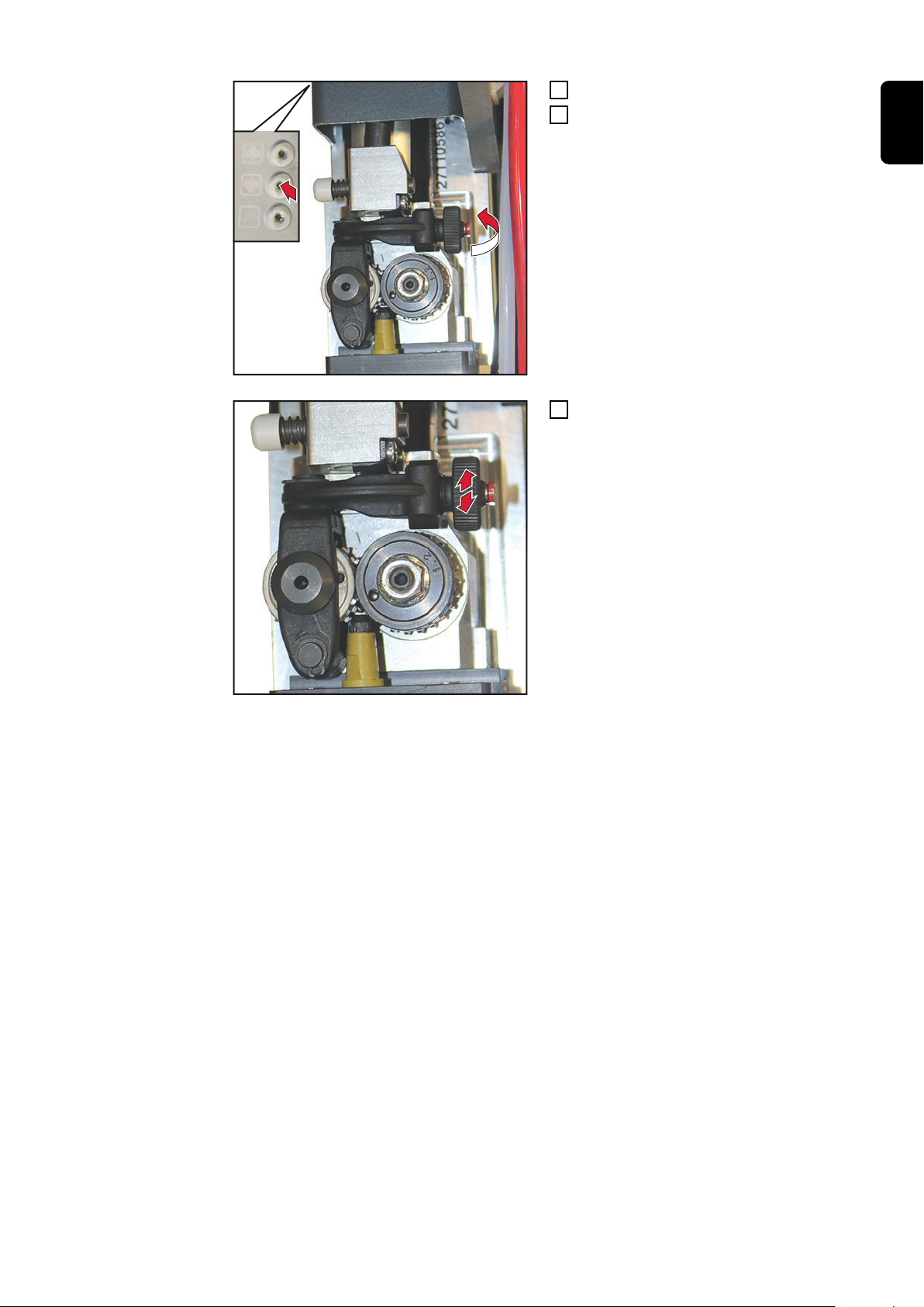
7
6
Close clamping stirrup
8
8
6
Press the wire threading button until
7
the wire electrode comes out of the
welding torch
Set contact pressure
8
EN-US
57
Page 58
Setting up Laser Welding Head
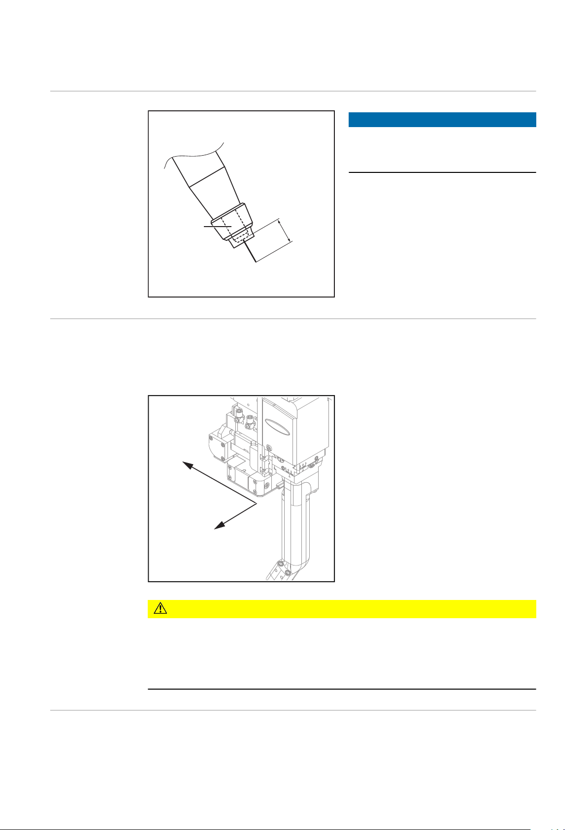
14 mm
(1)
(2)
(3)
x (± 2 mm)
y (± 3 mm)
Stick Out
Adjustable axes The spatial position of the arc process in relation to the laser beam can be adjusted in
two Cartesian coordinate axes:
An adjustment in the z axis can only take place via the collimation of the laser optics.
NOTE!
When setting the spatial position of the
welding torch, pay attention to a general stick out of 14 mm.
(1) Welding torch
(2) Contact tip
(3) Stick Out
Adjustment
device on the
laser welding
head
58
CAUTION!
Risk of damage to the optical fiber due to the laser welding head being perpendicular to the workpiece surface.
If the laser optics unit is at 90° to the workpiece surface, then the laser beam is reflected
directly into the laser optics. This may cause serious damage to the optical fiber.
Always guide the laser welding head to be trailing or leading!
▶
The laser welding head is equipped with an adjustment device, which allows for precise
positioning in the x and y coordinate axis.
Page 59
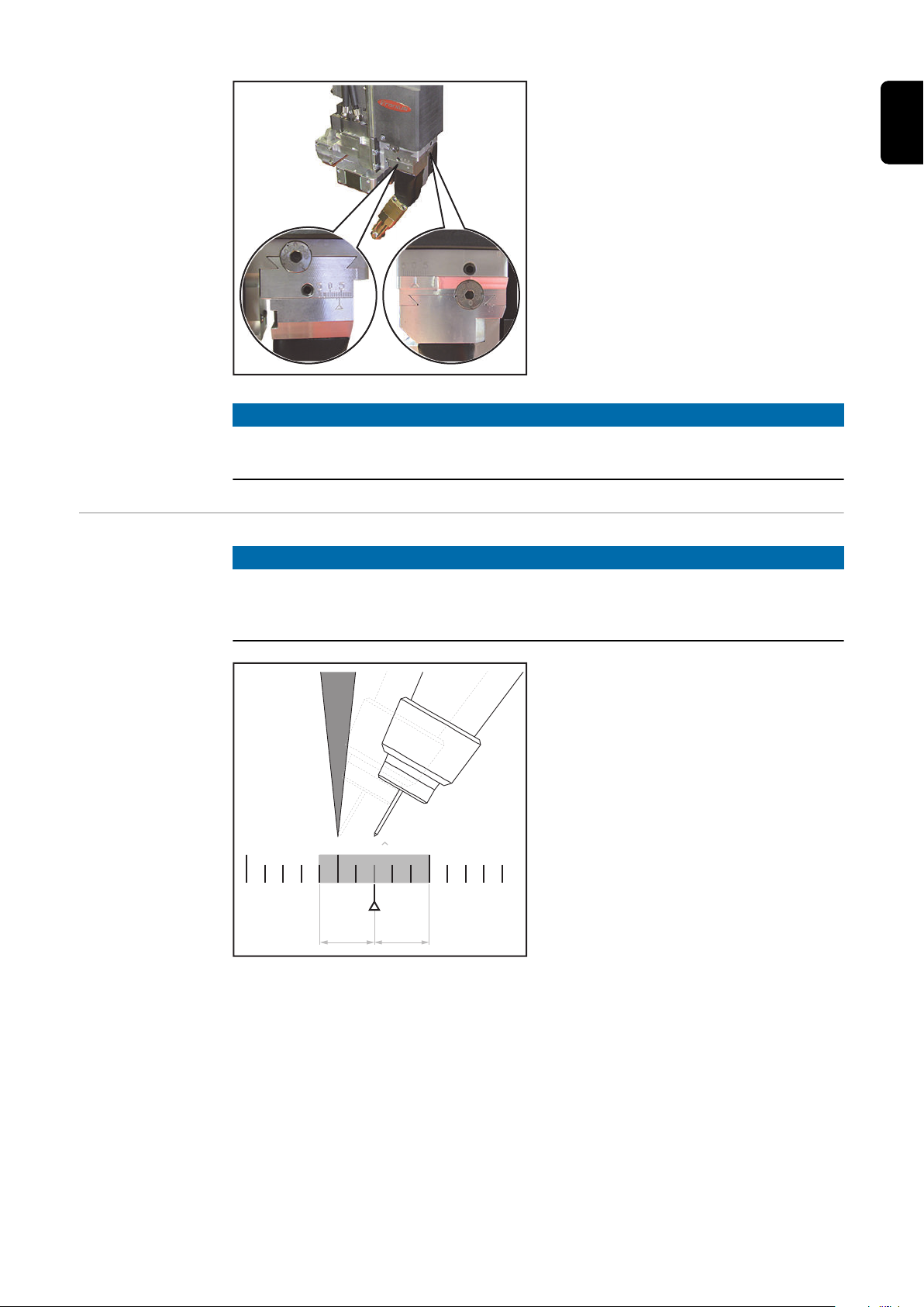
x
y
(1)
(2)
(1)
(2)
The adjustment device essentially consists
0 5
5
+ 3 mm
=
2 0
- 3 mm
of:
Adjusting the x
axis
(1) Adjustment screw with gauge
Allen screw,
size 3 mm
¼-turn corresponds to an adjustment path of 0.25 mm
(2) Scale depicting adjustment range
NOTE!
When using a steel welding torch inner liner, the welding potential may be present
at the laser welding head's adjustment unit!
NOTE!
The x adjustment range of ± 3 mm starts from the second graduation mark on the
x scale.
The laser and wire electrode are in the same position in position 0.
EN-US
59
Page 60

(1)
(2)
Loosen the threaded pin (1),
(1)
(2)
1
size 3 mm
Adjust the x axis using the adjustment
2
screw (2) and Allen key, size 3 mm:
one turn corresponds to 1.0 mm
After adjusting the x axis, re-tighten
3
the threaded pin (1)
Adjusting the y
axis
Loosen the threaded pin (1),
1
size 3 mm
Adjust the y axis using the adjustment
2
screw (2) and Allen key, size 3 mm:
one turn corresponds to 1.0 mm
After adjusting the y axis, re-tighten
3
the threaded pin (1)
60
Page 61
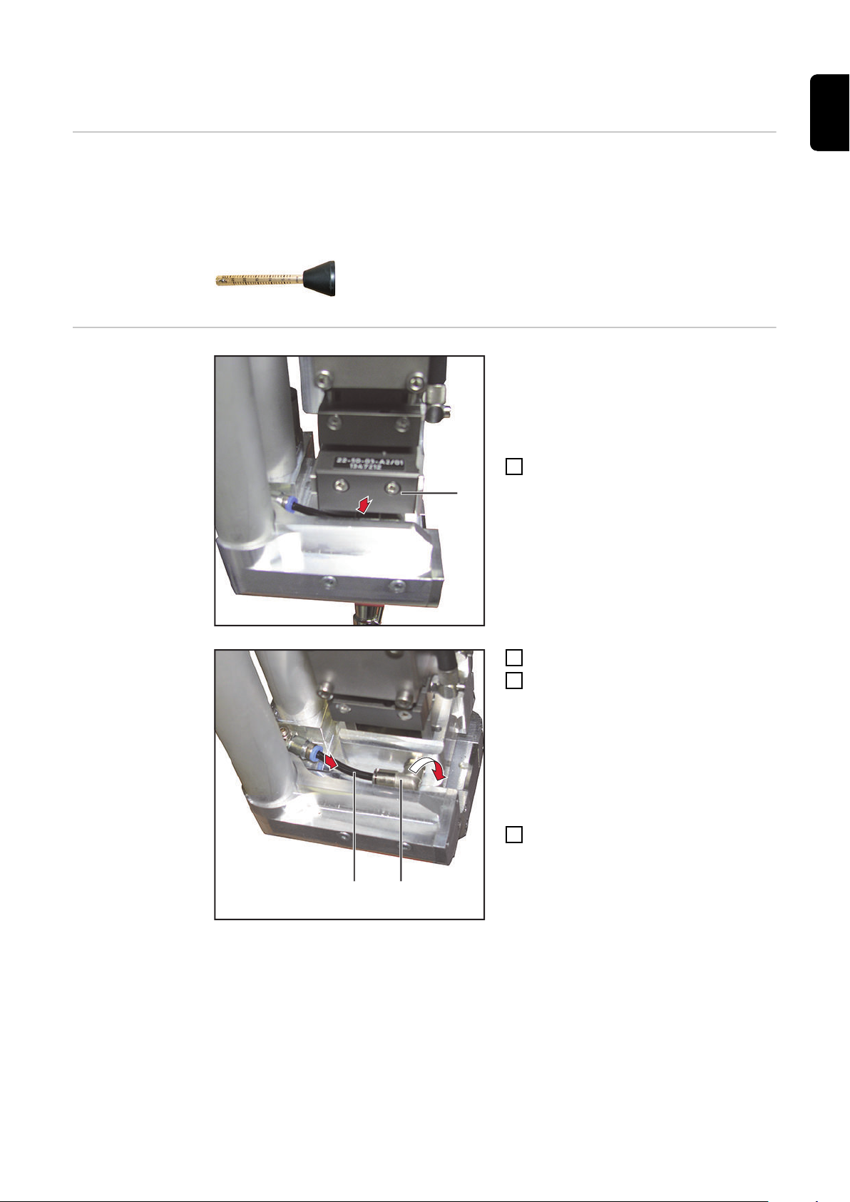
Set the radial airflow
(1)
1
(2) (3)
2
3
Requirements IMPORTANT! The radial airflow must be adjusted before starting-up the laser welding
head.
The flow volume meter from the laser welding head's scope of supply is required to adjust the radial airflow.
EN-US
Setting the radial
airflow
IMPORTANT! When removing the protect-
ive glass tray, make sure that this is not
contaminated, scratched, or otherwise
damaged.
Remove the protective glass tray (1)
1
from the laser optics
Disconnect the air hose (2)
2
Swivel the air connection (3) to the
3
side
IMPORTANT! When inserting the protective glass tray, make sure that this is not
contaminated, scratched, or otherwise
damaged.
Re-insert the protective glass tray
4
61
Page 62
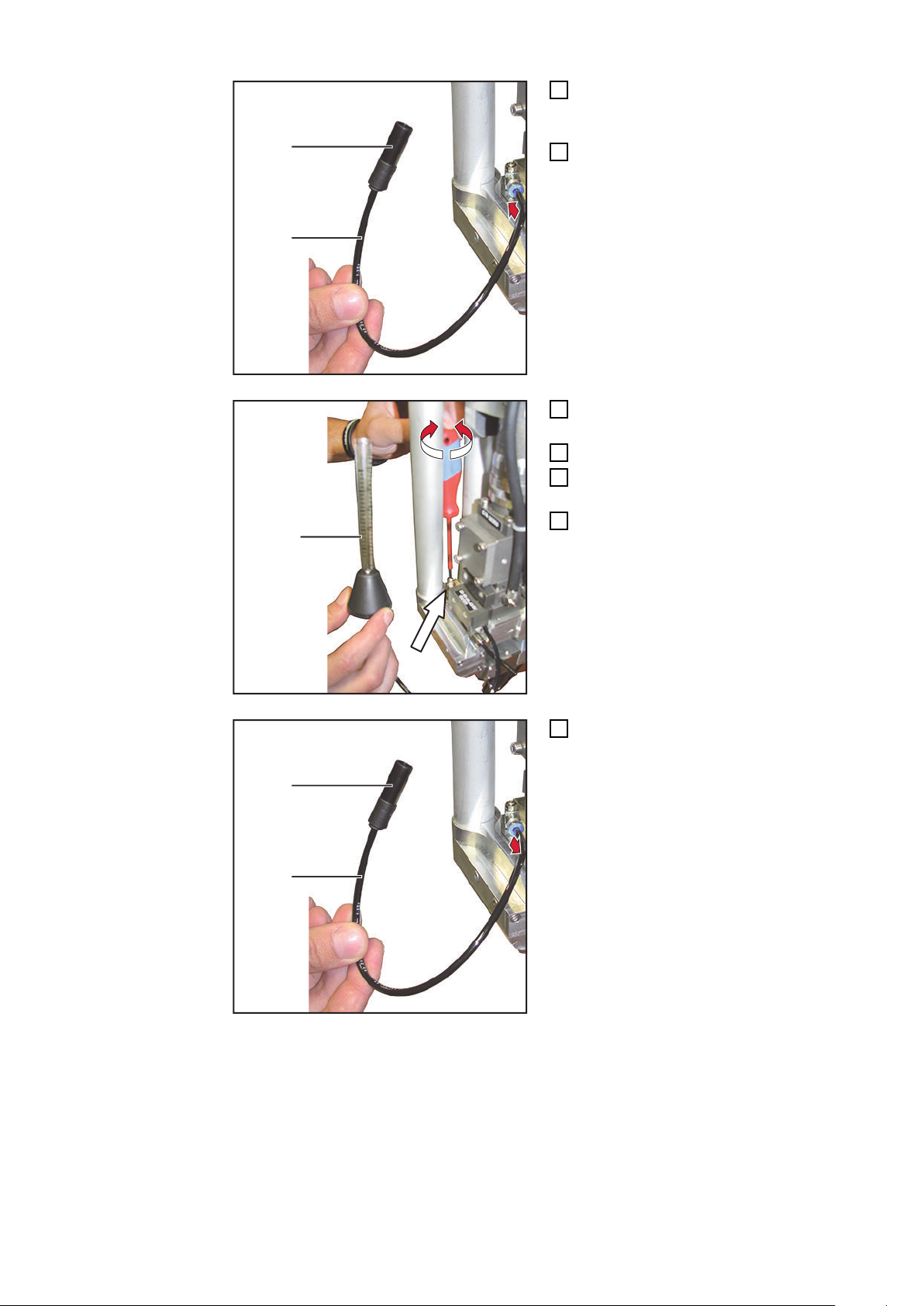
(4)
(5)
6
Connect the hose (5) and adapter (4)
(6)
(4)
(5)
11
5
from the laser welding head's scope of
supply
Connect the hose
6
Fit the flow volume meter (6) on the
7
hose and adapter
Open the air supply
8
Adjust the air volume to 25 l/min using
9
a slotted screwdriver
Remove the flow volume meter (6)
10
Disconnect the hose (5) and adapter
11
(4)
62
Page 63
(2) (3)
14
13
IMPORTANT! When removing the protect-
(1)
15
ive glass tray, make sure that this is not
contaminated, scratched, or otherwise
damaged.
Remove the protective glass tray from
12
the laser optics
Swivel the air connection (3) back
13
Connect the air hose (2)
14
IMPORTANT! When inserting the protect-
ive glass tray, make sure that this is not
contaminated, scratched, or otherwise
damaged.
Insert the protective glass tray (1)
15
EN-US
63
Page 64

Creating Reference Program
y
x
r
z
(1)
(1)
y
Safety
Work performed incorrectly can cause serious injury and damage to property.
▶
▶
General A low-power pilot laser is required for the adjustment work described.
A reference program must be created:
- after initial installation of the laser welding head
- when programing a new component, if the x and y values on the adjustment units
Create a Reference Program
The scope of supply for the laser welding head includes a metal gauge for the exact adjustment of the wire electrode position in comparison with the laser focus.
This gauge is mounted in the working area of the robot and is used to create a reference
program for the series components.
Create a reference program before welding the first series component
WARNING!
This setting work must only be carried out by trained and qualified personnel.
Observe the safety rules in the OI, in particular the "Safety Inspection" section.
have changed.
Requirement:
- The laser welding head must be set up and completely connected.
- The wire electrode must be threaded in.
- The respective stick out must be set for the wire electrode.
- Observe the focal width specification on the laser optics
Mount gauge (1) in the working area of the robot
1
Switch on the pilot laser
2
Use the robot to position the laser welding head so that the laser optics are at an
3
angle of 90° to the gauge
Default setting for the parameter finding of
the component to be welded:
Using the robot, approach the gauge
4
so that the laser focus is in the cross
hairs of the gauge
Using the robot, lower the laser weld-
5
ing head until the wire electrode
touches the gauge
Use the x and y adjustment units on
6
the laser welding head to position the
wire electrode in relation to the laser
focus
64
standard value:
r = 3 mm
Page 65

Document the distance of the wire electrode to the laser focus in the x and y axis in
7
accordance with the scaling on the gauge
Save the settings in the robot as the reference program
8
Conduct test welding
9
The best welding result is used as the basis for the reference program.
If changes are required to the mechanical x/y settings on the basis of the test weld-
10
ing, overwrite the reference program that was initially created
EN-US
65
Page 66

Signal Sequence for LaserHybrid Welding
Safety
WARNING!
Work performed incorrectly can cause serious injury and damage to property.
The welding process may only be programmed by trained personnel.
▶
Observe the safety rules in the OI, in particular the "Safety Inspection" section
▶
CAUTION!
Risk of damage to the optical fiber due to the laser welding head being perpendicular to the workpiece surface during welding.
If the laser optics unit is at 90° to the workpiece surface, then the laser beam is reflected
directly into the laser optics. This may cause serious damage to the optical fiber.
Always guide the laser welding head to be trailing or leading!
▶
NOTE!
When welding lots of short weld seams in direct succession, only switch off the
CrossJet flow and external extraction system at the end of the entire process.
This will avoid contamination of the protective glass due to welding fumes.
Signal Sequence
for LaserHybrid
Welding
Robot start position:
Set signal "Extraction on"
1
Set signal "Crossjet on"
2
NOTE!
The "VALVE ON" signal for controlling the solenoid valve in the SplitBox SB 360i
LaserHybrid is transmitted to bit 26 (start counting with 0).
If preheating is not required, continue from "LaserHybrid welding start position."
Preheating start position:
Requirement: The laser must be ready for beam release.
Set signal "Gas test"
1
Set signal "Laser on"
2
The following factors determine the preheating temperature:
Travel speed
Laser output
Distance to the workpiece surface
66
Preheating end position:
Reset signal "Laser on"
1
Reset signal "Gas test"
2
LaserHybrid welding start position:
Page 67

Requirement: The laser must be ready for beam release.
Set signal "Arc on"
1
Wait for the current flow signal ("arc standing")
2
Set signal "Laser on"
3
Set signal "Start robot"
4
LaserHybrid welding end position:
Stop robot movement
1
Reset signal "Laser on"
2
Reset signal "Welding on"
3
Wait until the current flow signal = zero
4
Robot end position:
IMPORTANT! The robot end position is not the end of the weld seam.
Reset signal "Crossjet on"
1
Reset signal "Extraction on"
2
EN-US
67
Page 68

Measures before Starting Welding
Measures before
Starting Welding
Check the coolant flow on the laser optics cooling system
1
Check the coolant flow on the welding torch cooling system
2
(visual inspection in the coolant tank of the cooling unit)
Check whether a protective glass is present in the laser optics
3
Check whether all covers are correctly mounted on the laser welding head
4
Test CrossJet
5
Test extraction
6
Test shielding gas
7
68
Page 69

Operation Recommendations for LaserHybrid Welding System
Recommendations for the operation of a LaserHybrid welding
system
EN-US
For smooth operation, the following items should always be available when using a
LaserHybrid welding system:
LaserHybrid service station
Compressed-air gun supplied with 6 bar
Mobile tool trolley with the following tools and spare parts:
- 20 x contact tips, for each diameter
- 10 x gas distributors
- 4 x gas nozzles
- 4 x welding torch inner liners (already cut to length)
- One drive roller set incl. compression lever with axles
- Allen key set
- Diagonal cutting pliers
- Release spray
- Optics cleaning set from the respective optics manufacturer
- 1 x protective glass tray, packed to be dust-proof (as reserve)
- Min. 10 x protective glasses, packed to be dust-proof
Specifications for
the compressed
air supply
IMPORTANT! Always have a reserve laser welding head incl. optics in stock!
- Delivery time for a new laser welding
head:
- Delivery time for laser optics: min. 8 weeks!
- Repair of laser optics: min. 8 weeks!
IMPORTANT! Throughout all servicing on the laser welding head, the external extraction
system must be switched on.
To ensure proper functioning, the following specifications for the compressed air supply
must be met:
- Compressed air supply constant at min. 5 bar
- Compressed air free of oil
- Compressed air free of water
- Compressed air free of dust – no contaminants larger than 5 µm
min. 8 weeks!
69
Page 70

70
Page 71

Maintenance
71
Page 72

72
Page 73

Replacing the Welding Torch and Welding Torch
1
2
Wearing Parts
Safety
Risk of burns due to the intensely heated welding torch during operation.
The welding torch may only be cleaned, and its components checked, once it has
▶
cooled down.
Welding Torch
Spare Parts
EN-US
CAUTION!
Replacing the
Welding Torch
Remove Allen screws,
1
size 2.5 mm
Remove the media coupling cover
2
73
Page 74
4
3
Remove Allen screws,
5
6
5
5
2
2
1
1
2
2
1
1
3
size 4 mm
Disconnect the media coupling
4
tightening torque for assembly:
4 Nm
Remove three Allen screws,
5
size 3 mm
tightening torque for assembly:
2,5 Nm
Remove the welding torch in a down-
6
wards direction
Replacing welding torch wearing
parts
View from below
1
Install by performing the steps in the reverse order
IMPORTANT! When assembling the welding torch, pay attention to the condition
and presence of the O-rings.
2
Replacing the gas nozzle
(Allen key, size 4 mm)
74
Replacing the union nut
(flat spanner, 12 mm)
Replacing the contact tip
Page 75
2
1
3
Replacing the welding torch inner liner
EN-US
75
Page 76

Replace the spatter guard plate
(1)
(2)
(3)
2
(1)
1
(3)
(2)
(1)
Removing the
Spatter Guard
Plate
Mounting the
Spatter Guard
Plate
Remove Allen screws (1) and (2),
1
size 3 mm
Slide the spatter guard plate (3) to the
2
rear and remove
Engage the spatter guard plate (1)
1
and slide forwards
76
Mount the spatter guard plate (1) with
2
two Allen screw (2) and (3)
size 3 mm
Page 77
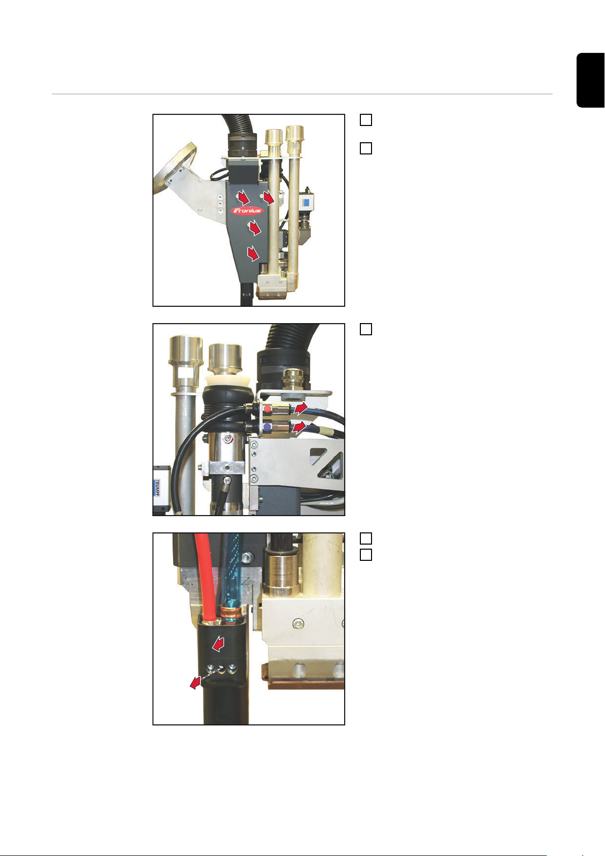
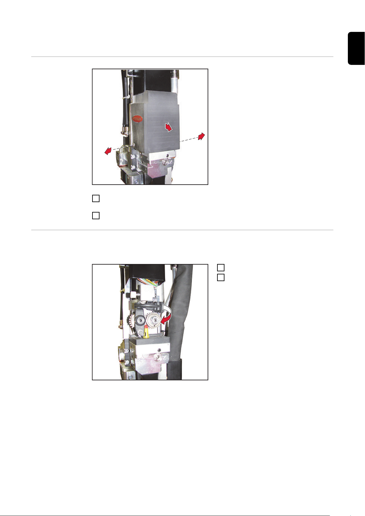
Replace the LaserHybrid UC hosepack
1
1
1
2
3
3
5
4
EN-US
Removing the
LaserHybrid UC
Hosepack
Remove three Allen screws
1
size 4 mm
Remove cover
2
Disconnect the coolant hose
3
Remove Allen screw, size 2.5 mm
4
Remove the media coupling cover
5
77
Page 78
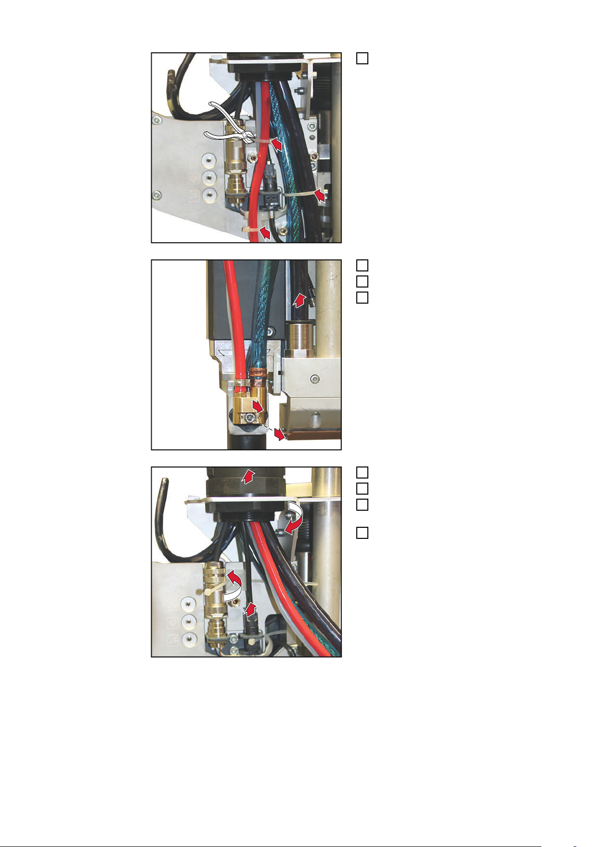
6
6
6
Loosen the three cable ties
8
7
9
12
11
1
3
10
6
Remove the Allen screw, size 4 mm
7
Disconnect the media coupling
8
Disconnect the hose
9
Unscrew the coupling
10
Disconnect the black cable
11
Unscrew the hexagonal nut
12
size 46 mm
Pull the LaserHybrid UC hosepack up
13
and out
78
Page 79
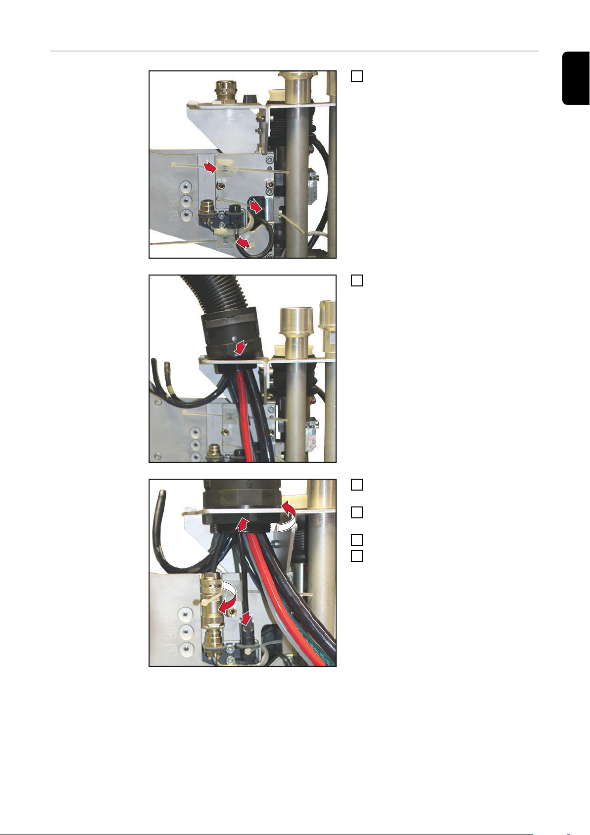
Connect the
1
1
1
2
3
6
4
5
LaserHybrid UC
Hosepack
Fasten the three cable ties
1
Insert the LaserHybrid UC hosepack
2
into the opening from above
EN-US
Slide the hexagonal nut over the
3
hosepack components
Tighten the hexagonal nut
4
size 46 mm
Screw in the coupling
5
Connect the black cable
6
79
Page 80

9
7
8
Connect the hose
10
10
10
1
1
12
7
Position the media coupling
8
Mount the media coupling with the Al-
9
len screw
size 4 mm
Fasten the hosepack components with
10
three cable ties;
cut the cable ties to length
Position the media coupling cover
11
Mount the media coupling cover with
12
an Allen screw, size 2.5 mm
80
Page 81

1
3
1
3
Connect the coolant hoses
14
15
15
15
13
The coolant supply hose with the blue
color marking is on the bottom.
Position the cover
14
Secure the cover with three Allen
15
screws, size 4 mm
EN-US
81
Page 82

Replacing the Laser Optics
1
3
2
2
a
b
b
c
Safety
Disconnecting
the fiber optic
cable from the
laser optics
WARNING!
Work performed incorrectly can cause serious injury and damage to property.
This assembly work must only be carried out by trained and qualified personnel.
▶
Observe the safety rules in the OI, in particular the "Safety Inspection" section.
▶
CAUTION!
Risk of damage to the laser welding head due to contamination from above.
Observe the Operating Instructions, specifications, and safety instructions provided
▶
by the laser optics manufacturer.
Before disconnecting the fiber optic cable from the laser optics, position the laser
▶
welding head so that the longitudinal axis of the laser welding head is outside the
horizontal (> 90°). This will ensure that no dirt can get into the laser optics from
above.
Position the laser welding head so that the longitudinal axis of the laser welding
1
head is outside the horizontal (> 90°)
Clean connection area using com-
2
pressed air
Disconnect the hoses for the optics
3
cooling supply (blue) and the optics
cooling return (red)
Remove the Allen screw, size 2.5 mm,
4
disconnect the optics cooling
82
Disconnect the fiber optic cable:
5
a) Press the button
b) Pull back the rubber sleeve in the
direction of the optics
c) Disconnect the connector for the
fiber optic cable
Page 83

5
6
Attach the protective cover on the con-
2
1
1
1
3
5
5
4
4
6
nector of the fiber optic cable
Attach the protective cover on the con-
7
nection socket of the fiber optic cable
Connect the fiber optic cable to the laser optics as specified in the "Connecting the laser
optics" section from page 49.
EN-US
Removing the
Laser Optics
Remove three Allen screws
1
size 4 mm
Remove cover
2
Disconnect the hose for additional ex-
3
traction
Remove two Allen screws
4
size 3 mm
Slide the spatter guard plate to the
5
rear and remove
83
Page 84

7
6
6
Remove the two Allen screws
8
9
13
1
0
11
12
15
14
14
6
Move the extraction tube
7
Unscrew the CrossJet extraction tube
8
Move the extraction tube so that the
9
protective glass can be removed
IMPORTANT! When removing and inserting the protective glass, make sure that
this is not contaminated, scratched, or otherwise damaged.
Remove the protective glass from the
10
laser optics
Disconnect the air hose
11
Swivel the air connection to the side
12
Re-insert the protective glass
13
Remove two Allen screws
14
size 3 mm
Swivel the CrossJet to the side
15
84
Page 85

16
16
16
16
View from below
18
18
17
17
19
20
Remove the four Allen screws on the
16
underside of the laser welding head
size 2.5 mm
Remove two Allen screws
17
size 3 mm
Remove two Allen screws
18
size 3 mm
Remove the bracket
19
EN-US
Remove the laser optics
20
85
Page 86

Assembly Posi-
(A)
(B)
(1)
1
tions for Installing the Laser
Optics
E.g. laser optics with camera module (1)
(without camera)
(A) Assembly position for laser optics with camera module
(B) Assembly position for laser optics without camera module
Installing the
laser optics
IMPORTANT! When replacing the laser optics, ensure that the laser optics and welding
torch match in terms of the focal length.
IMPORTANT! When inserting the laser optics, make sure that the register pins on
the underside of the laser optics are located in the openings provided.
Insert the laser optics into the laser
1
welding head
86
Page 87

2
2
2
2
View from below
5
4
3
4
5
7
6
6
7
Insert and tighten the four Allen
2
screws on the underside of the laser
welding head
size 2.5 mm
Mount the bracket
3
Loosely mount the bracket with two Al-
4
len screws (do not tighten)
size 3 mm
Loosely fasten the two Allen screws
5
(do not tighten)
size 3 mm
EN-US
Tighten the two Allen screws
6
size 3 mm
tightening torque = 2.5 Nm
Tighten the two Allen screws
7
size 3 mm
tightening torque = 2.5 Nm
87
Page 88

9
8
9
Swivel the CrossJet into position
10
14
11
1
3
15
12
17
16
17
8
Mount CrossJet with two Allen screws
9
3 mm
tightening torque = 2.5 Nm
Move the extraction tube so that the
10
protective glass tray can be removed
IMPORTANT! When removing and inserting the protective glass tray, make sure
that this is not contaminated, scratched, or
otherwise damaged.
Remove the protective glass tray from
11
the laser optics
Swivel the air connection back
12
Connect the air hose
13
Re-insert the protective glass tray
14
Screw in the CrossJet extraction tube
15
Position the extraction tube
16
Fasten the extraction tube with two Al-
17
len screws
size 3 mm
tightening torque = 2.5 Nm
88
Page 89

18
1
9
18
1
9
Position the spatter guard plate
22
20
21
21
21
18
Mount the spatter guard plate with two
19
Allen screws
size 3 mm
Position the cover
20
Mount the cover with three Allen
21
screws
size 4 mm
Connect the hose for the additional
22
extraction
EN-US
Connect the fiber optic cable as spe-
23
cified in the "Connecting the laser optics" section from page 49.
89
Page 90
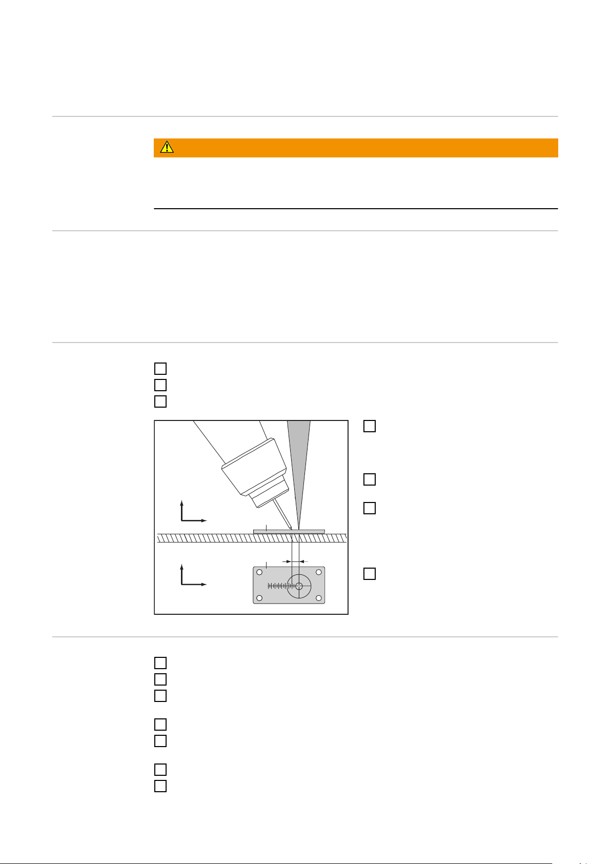
Checking Position of the Wire Electrode in relation
y
x
r
z
(1)
(1)
y
to the Laser Focus
Safety
Work performed incorrectly can cause serious injury and damage to property.
▶
▶
General A pilot laser with low power is required for the described adjustment work.
Check the position of the wire electrode in relation to the laser focus:
- Each time the laser welding head is replaced
- Each time the laser optics are replaced
- Each time the welding torch is changed
Checking Position of the Wire
Electrode in relation to the Laser
Focus
1
2
3
WARNING!
This setting work must only be carried out by trained and qualified personnel.
Observe the safety rules in the OI, in particular the "Safety Inspection" section.
Switch off MIG/MAG power source
Replace components
Switch on MIG/MAG power source
Using the robot, move to the reference
4
point on the gauge (1):
the laser focus is in the cross hair on
the gauge
Thread the wire electrodes up to the
5
gauge
Check the position of the wire elec-
6
trode in relation to the laser focus:
The position of the wire electrode
must match the values documented
on the gauge using scaling.
If necessary, correct the position of the
7
wire electrode in relation to the laser
focus using the x- and y-adjustment
mechanisms
Example: Use of
the Reference
Program after
Welding Torch
Replacement
90
Switch off power source
1
Change welding torch
2
Welding torch replacement is complete, wearing parts have been installed:
3
switch on power source
Adjust the stick out according to application
4
Upload the reference program and slowly approach the reference position on the ad-
5
justment gauge
Thread in wire electrode until this touches the adjustment gauge
6
Check the position of the wire electrode to the laser focus
7
Page 91

Only if the position is incorrect:
8
correct the x/y position on the mechanical setting options for the laser welding head
– NOT on the robot
IMPORTANT! Under no circumstances should the robot reference program be overwritten!
Start of production
9
EN-US
91
Page 92

Measures to Reduce Contamination of the Optics
Measures to Reduce Contamination of the Optics
Crossjet and Extraction
1. Please observe the values for the crossjet and extraction specified in these Operating Instructions.
2. Switch on the crossjet and extraction at least five seconds before the start of welding.
3. Do not switch off the crossjet and extraction until the laser welding head is safely in
the smoke-free zone.
Protective Glass (including Replacement)
IMPORTANT! Before changing the protective glass drawer, clean the area around it with
a cleaning cloth.
The environment must be clean when the protective glass drawer is being replaced.
4. To prevent dust from penetrating the focusing lens, the laser welding head must be
vertical when the protective glass is being changed (welding torch pointing toward
the floor).
5. Before changing the protective glass:
- Switch on the extraction and crossjet
- Clean the welding head with compressed air as best as you can
IMPORTANT Do not blast the protective glass with the air current directly.
- Switch off crossjet
- Replace protective glass
IMPORTANT When replacing the protective glass, the extraction must be
switched on and crossjet switched off.
6. Keep the amount of time the protective glass drawer is open to the minimum necessary.
7. If there are welding fumes on the protective glass, replace the protective glass with a
new pane of glass.
The contaminated protective glass can be used again:
- Pre-clean the protective glass with a cloth
- Finish cleaning the protective glass with a cotton swab soaked in methanol
- Store the protective glass in a dust-free area
8. If there is welding spatter on the protective glass, the protective glass must be replaced with a new pane of glass immediately.
Dispose of the protective glass that has welding spatter.
9. Check the protective glass from time to time at the start of production in order to determine a change interval specific to the application.
92
Automated Torch Cleaning Device
10. When using an automatic torch cleaning device:
Switch on the crossjet and extraction during the cleaning process.
Page 93

Changing the Fiber Optic Cable
11. The laser welding head must be in a horizontal position when you are changing the
fiber optic cable so that no dust can fall into the optics from above.
IMPORTANT! Clean with compressed air before changing.
EN-US
93
Page 94

94
Page 95

Appendix
95
Page 96

96
Page 97

Technical data
EN-US
Laser welding
head WF 25i
LaserHybrid UC
WF 25i LaserHybrid 4 kW UC
Max. laser performance on the workpiece 4000 W
Weight (without laser optics) 7 kg
Laser optics Trumpf BEO D35/F200
Duty cycle of the laser optics 100% at 4 kW and per minute
Dimensions 360 x 150 x 514 mm
Max. current carrying capacity
(100% D.C. at 40 °C)
M21 (EN439)
C1 (EN 439)
WF 25i LaserHybrid 6 kW UC
Max. laser performance on the workpiece 6000 W
Weight (without laser optics) 7 kg
Laser optics Trumpf BEO D35/F300
Duty cycle of the laser optics * 60% at 6 kW and per minute
250 A
250 A
LaserHybrid
Hosepack MHP
360i LH-UC
Dimensions 360 x 150 x 610 mm
Max. current carrying capacity
(100% D.C. at 40 °C)
M21 (EN439)
C1 (EN 439)
* Corresponds to 36 s of welding, 24 s break
Max. welding current (100% ED at 40°C) 360 A
Wire diameter 1.0–1.6 mm
Voltage rating (V-Peak) 141 V
Cooling system Liquid cooling
Coolant Original Fronius coolant
Hosepack length 4.2/7.5 m
Lowest cooling capacity as per IEC 60974-2,
depending on the hosepack length
Coolant pressure min./max. 3.0/5.0 bar
Minimum flow of coolant 1.0 l/min
1400/1500 W
360 A
360 A
This product meets the requirements set out in standard IEC 60974-7.
97
Page 98

SB 360i LH
Supply voltage 24 V DC / 60 V DC
Nominal current 0.5 A / 0.8 A
Welding current at 10 min / 40 °C (104 °F) 40% D.C.* 500 A
60% D.C.* 450 A
100% D.C.* 360 A
Maximum pressure of shielding gas 7 bar/101.53 psi
Coolant Original Fronius
Maximum pressure of coolant 5 bar/72.53 psi
Protection class IP 20
Mark of conformity CE
Dimensions l × w × h 560.4 x 334.93 x 113 mm
22.06 x 13.19 x 4.45 in.
Weight 9.6 kg/21.16 Ib
*) D.C. = duty cycle
98
Page 99

EN-US
99
Page 100

Fronius International GmbH
Froniusstraße 1
4643 Pettenbach
Austria
contact@fronius.com
www.fronius.com
Under www.fronius.com/contact you will find the adresses
of all Fronius Sales & Service Partners and locations.
spareparts.fronius.com
SPAREPARTS
ONLINE
 Loading...