

Page 1

Fronius prints on elemental chlorine free paper (ECF) sourced from certified sustainable forests (FSC).
/ Perfect Charging / Perfect Welding / Solar Energy
WF 25i LaserHybrid 10 kW
SB 360i LaserHybrid
Operating Instructions
LaserHybrid
EN-US
[
42,0426,0279,EN 010-19032020
Page 2

2
Page 3

Table of contents
Safety Instructions ..................................................................................................................................... 7
Explanation of Safety Instructions......................................................................................................... 7
General ................................................................................................................................................. 7
Intended Use......................................................................................................................................... 8
Environmental Conditions..................................................................................................................... 8
Obligations of the Operating Company................................................................................................. 8
Obligations of Personnel....................................................................................................................... 8
Personal Protective Equipment............................................................................................................. 9
Danger from Toxic Gases and Vapors.................................................................................................. 9
Danger Posed by Shielding Gas Leak.................................................................................................. 9
Danger from Flying Sparks ................................................................................................................... 10
Danger from Welding Current ............................................................................................................... 10
Stray Welding Currents......................................................................................................................... 10
EMC Measures ..................................................................................................................................... 10
Particular Hazard Areas........................................................................................................................ 11
Informal Safety Measures..................................................................................................................... 12
Safety Measures at the Installation Location ........................................................................................ 13
Safety Measures in Normal Operation.................................................................................................. 13
Safety Inspection .................................................................................................................................. 13
Modifications ......................................................................................................................................... 14
Spare and Wearing Parts...................................................................................................................... 14
Calibrating Power Sources ................................................................................................................... 14
The CE label ......................................................................................................................................... 14
Copyright............................................................................................................................................... 14
EN-US
General Information 15
General ...................................................................................................................................................... 17
General ................................................................................................................................................. 17
Intended Use......................................................................................................................................... 17
Applications........................................................................................................................................... 17
Scope of Supply.................................................................................................................................... 18
Optional Components ........................................................................................................................... 19
Gas nozzle cross jet.............................................................................................................................. 19
Requirements............................................................................................................................................. 20
Mechanical Requirements .................................................................................................................... 20
Robot Requirements ............................................................................................................................. 20
Ground Connection............................................................................................................................... 20
Alignment .............................................................................................................................................. 21
System Overview ....................................................................................................................................... 22
System Overview .................................................................................................................................. 22
Other LaserHybrid Systems.................................................................................................................. 23
Setup Variants ...................................................................................................................................... 25
Operating controls and connections 27
Product description .................................................................................................................................... 29
Device Description WF 25i LaserHybrid 10 kW .................................................................................... 29
Device Description, SB 360i LaserHybrid ............................................................................................. 30
Collision Protection .................................................................................................................................... 32
General ................................................................................................................................................. 32
Safety.................................................................................................................................................... 32
Checking the Reference Point after a Collision .................................................................................... 32
Signal Analysis...................................................................................................................................... 32
Connection Specifications.......................................................................................................................... 33
Connection Specifications..................................................................................................................... 33
Compressed Air Diagram...................................................................................................................... 35
Pressure Monitoring in the SplitBox SB 360i LaserHybrid.................................................................... 35
3
Page 4

Commissioning 37
General ...................................................................................................................................................... 39
Safety.................................................................................................................................................... 39
Setup Regulations................................................................................................................................. 39
Grid Connection .................................................................................................................................... 39
Set Up LaserHybrid Welding System.................................................................................................... 40
Installing the Laser Welding Head on the Robot........................................................................................ 41
Connection Options on the Robot......................................................................................................... 41
Installing the Laser Welding Head on the Robot................................................................................... 41
Installing and Connecting SplitBox SB 360i LaserHybrid .......................................................................... 42
Installing SplitBox SB 360i LaserHybrid on Robot................................................................................ 42
Connecting SplitBox SB 360i LaserHybrid............................................................................................ 44
Connecting Crossjet................................................................................................................................... 46
Connecting the CrossJet....................................................................................................................... 46
Connecting LaserHybrid Hosepack to Laser Welding Head...................................................................... 48
Connecting LaserHybrid Hosepack to Laser Welding Head................................................................. 48
Connecting/changing Wirefeeding Hose to/on Laser Welding Head.................................................... 49
Installing/Changing Wirefeed Rollers......................................................................................................... 50
Installing/Changing Wirefeed Rollers.................................................................................................... 50
Connecting Laser Optics and Extra Extraction .......................................................................................... 51
Connecting Laser Optics....................................................................................................................... 51
Connecting Extra Extraction ................................................................................................................. 54
Preparing Welding Torch ........................................................................................................................... 57
Preparing Welding Torch ...................................................................................................................... 57
Installing Hosepack on Robot .................................................................................................................... 59
Placing the Hosepack on the Robot...................................................................................................... 59
Threading the Wire Electrode .................................................................................................................... 61
Threading the Wire Electrode ............................................................................................................... 61
Setting up Laser Welding Head ................................................................................................................. 62
Stick Out ............................................................................................................................................... 62
Adjustable Axes .................................................................................................................................... 63
Adjustment Mechanisms on the Laser Welding Head .......................................................................... 64
Setting Up X-Axis.................................................................................................................................. 65
Setting Up Y-Axis.................................................................................................................................. 66
Setting Up Z-Axis .................................................................................................................................. 67
Creating Reference Program ..................................................................................................................... 68
Safety.................................................................................................................................................... 68
General ................................................................................................................................................. 68
Creating Reference Program ................................................................................................................ 68
Signal Sequence for LaserHybrid Welding ................................................................................................ 70
Safety.................................................................................................................................................... 70
Signal Sequence for LaserHybrid Welding ........................................................................................... 70
Measures before Starting Welding............................................................................................................. 72
Measures before Starting Welding........................................................................................................ 72
Operation Recommendations for LaserHybrid Welding System................................................................ 73
Operation Recommendations for LaserHybrid Welding System........................................................... 73
Specifications for the compressed-air supply ....................................................................................... 73
Maintenance 75
Replacing the Welding Torch and Welding Torch Wearing Parts.............................................................. 77
Safety.................................................................................................................................................... 77
Welding Torch Spare Parts................................................................................................................... 77
Replacing the Welding Torch................................................................................................................ 77
Replacing Welding Torch Wearing Parts .............................................................................................. 79
Replacing the Spatter Guard Plate and Extra Extraction........................................................................... 80
Replacing the Spatter Guard Plate ....................................................................................................... 80
Replacing the Extra Extraction.............................................................................................................. 80
Replacing the Laser Optics........................................................................................................................ 81
Safety.................................................................................................................................................... 81
Replacing the Trumpf Laser Optics ...................................................................................................... 81
Preparation ........................................................................................................................................... 81
4
Page 5

Removing the Laser Optics................................................................................................................... 84
Inserting the Laser Optics..................................................................................................................... 86
Checking/Adjusting Laser Optics Focus ............................................................................................... 89
Fixing the Laser Optics ......................................................................................................................... 91
Final Tasks............................................................................................................................................ 92
Laser Optics – Overview....................................................................................................................... 94
Checking Position of the Wire Electrode in relation to the Laser Focus .................................................... 95
Safety.................................................................................................................................................... 95
General ................................................................................................................................................. 95
Checking Position of the Wire Electrode in relation to the Laser Focus ............................................... 95
Example: Reference Program Application after Welding Torch Change.............................................. 96
Measures to Reduce Contamination of the Optics .................................................................................... 97
Measures to Reduce Contamination of the Optics ............................................................................... 97
Appendix 99
Technical Data ........................................................................................................................................... 101
WF 25i LaserHybrid 10 kW (laser welding head).................................................................................. 101
LaserHybrid hosepack MHP 360i LH.................................................................................................... 101
EN-US
5
Page 6

6
Page 7

Safety Instructions
EN-US
Explanation of
Safety Instructions
DANGER!
Indicates an immediate danger.
► Death or serious injury may result if appropriate precautions are not taken.
WARNING!
Indicates a possibly dangerous situation.
► Death or serious injury may result if appropriate precautions are not taken.
CAUTION!
Indicates a situation where damage or injury could occur.
► Minor injury or damage to property may result if appropriate precautions are not taken.
NOTE!
Indicates the possibility of flawed results and damage to the equipment.
General The LaserHybrid head has been manufactured using state-of-the-art technology and ac-
cording to recognized safety standards. If used incorrectly or misused, however, it can
cause
- injury or death to the operator or a third party,
- damage to the LaserHybrid head and other material assets belonging to the operating
company,
- inefficient operation of the LaserHybrid head.
All persons involved in the commissioning, operation, maintenance, and servicing of the
LaserHybrid head must
- be suitably qualified,
- have knowledge of welding and
- have read and implemented carefully these Operating Instructions and the OI for the
following system components:
Laser
Laser optics
Power source and associated wirefeeder
Robot and its controller
The Operating Instructions must always be at hand wherever the LaserHybrid head is being used. In addition to the Operating Instructions, all applicable local rules and regulations
regarding accident prevention and environmental protection must also be followed.
All safety instructions and warning signs on the LaserHybrid head itself must:
- be kept in a legible state
- not be damaged/marked
- not be removed
- not be covered, pasted, or painted over.
7
Page 8

For the location of the safety and danger notices on the LaserHybrid head, refer to the section headed "General" in the Operating Instructions for the LaserHybrid head.
Before switching it on, resolve any faults that could compromise safety.
Your personal safety is at stake!
Intended Use The LaserHybrid head is to be used exclusively for its intended purpose.
The LaserHybrid head is intended exclusively for LaserHybrid welding of aluminum, CrNi
and steel materials.
Any other use does not constitute proper use.
The manufacturer is not responsible for any damage resulting from improper use.
Proper use also means:
- Completely reading and obeying all instructions in the Operating Instructions
- Completely reading and obeying all safety instructions and danger notices
- Carrying out all the specified inspection and servicing work.
Never use the LaserHybrid head or the power source to thaw pipes.
The LaserHybrid head is designed for operation in industry and business. The manufac-
turer shall not be liable for any damage resulting from use in a living area.
The manufacturer shall not be liable for faulty or incorrect work results either.
Environmental
Conditions
Obligations of the
Operating Company
Operation or storage of the LaserHybrid head outside the stipulated area will be deemed
as not in accordance with the intended purpose. The manufacturer is not responsible for
any damage resulting from improper use.
Temperature range of the ambient air:
- During operation: -10°C to +40°C (14°F to 104°F)
- During transport and storage: -25°C to +55°C (-13°F to 131°F)
Relative humidity:
- Up to 50% at 40°C (104°F)
- Up to 90% at 20°C (68°F)
Ambient air: free of dust, acids, corrosive gases or substances, etc.
Altitude above sea level: up to 2000 m (6561 ft. 8.16 in.)
The operating company must only allow persons to work with the LaserHybrid head if they
- are familiar with the basic occupational safety and accident prevention regulations and
are trained in handling the LaserHybrid head
- have read and understood these Operating Instructions, especially the section "Safety
Rules," and have confirmed this with their signature
- are trained according to the requirements for the work results.
The safety-conscious work of the personnel must be checked regularly.
Obligations of
Personnel
8
All persons who are assigned to work with the LaserHybrid head must do the following before beginning work:
- Follow the basic regulations for occupational safety and accident prevention
- Read these Operating Instructions, especially the section "Safety Rules," and confirm
that they have understood and will follow them by signing
Before leaving the workplace, ensure that no personal injury or property damage can occur
in one's absence.
Page 9

Personal Protective Equipment
Please take the following precautions for your own personal safety:
Persons present in the sealed cell for the LaserHybrid process must
- wear rigid, wet-insulating footwear
- protect hands with appropriate gloves (featuring electrical insulation and thermal protection)
- protect their eyes from laser beams by wearing regulation-compliant safety glasses for
lasers. To protect their face and eyes against UV beams, further protection in the form
of a protective shield with regulation-compliant filter insert for laser protection class 4
must also be used in front of the safety glasses for lasers and the person's face. Do
not look into the laser beam, even with a regulation-compliant filter insert for laser protection class 4.
- Only wear suitable (flame-resistant) clothing
- Wear hearing protection designed for crossjet noise (120 dbA)
If there are persons present in the sealed cell for the LaserHybrid process,
- inform them of all the dangers that may be posed during operation (e.g. potential accumulation of gases hazardous to health, risk of asphyxiation due to lack of oxygen in
the breathable air, hazards posed by laser light, etc.)
- provide protective equipment
- construct protective walls or install protective curtains.
EN-US
Danger from Toxic Gases and Vapors
The fumes produced during welding contain toxic gases and vapors.
Welding fumes contain substances that may cause birth defects and cancer in some cir-
cumstances.
Keep your head out of the welding fumes and gases.
Take the following precautionary measures for fumes and harmful gases:
- Do not breathe them in.
- Extract them from the work area using appropriate equipment.
Ensure that there is sufficient fresh air.
Use breathing apparatus with air supply if there is insufficient ventilation.
When no welding is taking place, close the valve of the shielding gas cylinder or the main
gas supply.
If there is uncertainty as to whether the extraction capacity is sufficient, compare the measured toxic emission values against the permissible limit values.
The following components are factors that determine how toxic the welding fumes are:
- The metals used for the workpiece
- Electrodes
- Coatings
- Cleaning agents, degreasers, and the like
Danger Posed by
Shielding Gas
Leak
Consult the corresponding material safety data sheets and manufacturer's instructions for
the components listed above.
Keep flammable vapors (such as solvent vapors) out of the laser and arc radiation range.
Risk of asphyxiation due to uncontrolled shielding gas leak
9
Page 10

Shielding gas is colorless and odorless and may suppress the oxygen in the ambient air in
the event of leakage.
- Ensure there is a sufficient supply of fresh air with a ventilation flow rate of at least
20 m³ per hour.
- Please observe the safety and maintenance information for the shielding gas cylinder
or the main gas supply.
- When no welding is taking place, close the valve of the shielding gas cylinder or the
main gas supply.
- Always check the shielding gas cylinder or main gas supply for uncontrolled gas leakage before each start-up.
Danger from Flying Sparks
Danger from
Welding Current
Flying sparks can cause fires and explosions.
Never undertake welding near flammable materials.
Flammable materials must be kept at least 11 meters (35 ft.) from the LaserHybrid welding
process or protected with a certified cover.
Keep suitable, tested fire extinguishers on hand.
Sparks and pieces of hot metal may also get into surrounding areas through small cracks
and openings. Take appropriate measures to ensure that there is no risk of injury or fire.
Do not undertake welding in areas at risk of fire and explosion, or on sealed tanks, drums,
or pipes if these have not been prepared in accordance with corresponding national and
international standards.
Do not undertake welding on containers in which gases, fuels, mineral oils, and the like are/
were stored. Residues pose a risk of explosion.
An electric shock can be fatal. Every electric shock poses a risk of death.
All welding power-leads must be secured, undamaged, and insulated. Replace loose con-
nections and scorched cables immediately.
Stray Welding
Currents
EMC Measures WARNING! Electromagnetic field! Electromagnetic fields may cause health problems
If the following instructions are not observed, stray welding currents may occur, which can
result in the destruction of ground conductors, the power source used, the LaserHybrid
head, and other electrical equipment.
Ensure that the workpiece terminal is securely connected to the workpiece. If the floor is
electrically conductive, set up the power source so that it is insulated wherever possible.
that are not yet known.
The operator is responsible for ensuring that there is no electromagnetic interference with
electrical and electronic equipment.
If electromagnetic interference is discovered, the operator is obliged to take action to rectify
the situation.
10
Page 11

Check and evaluate possible problems and the interference immunity of equipment in the
vicinity according to national and international regulations:
- Safety devices
- Grid power lines, signal lines, and data transfer lines
- EMC and telecommunications equipment
- Devices for measuring and calibrating
- The health of persons close by, e.g., those with pacemakers and hearing aids
Persons with pacemakers must seek advice from their doctor before staying in the immediate vicinity of where the welding work is taking place.
Supporting measures to avoid EMC problems:
a) Grid power supply
- If electromagnetic interference occurs despite a grid connection that complies
with regulations, take additional measures (e.g., use a suitable grid filter).
b) Welding power-leads
- Keep them as short as possible
- Route them close together (also to avoid EMC problems)
- Route them far from other lines
c) Equipotential bonding
d) Workpiece grounding
- If necessary, establish grounding using suitable capacitors
e) Shield, if necessary
- Shield other devices in the vicinity
- Shield the entire welding installation
EN-US
Particular Hazard
Areas
Laser beam poses a risk of injury to the eyes. In addition to using the protective shield with
a regulation-compliant UV filter insert, eyes should be protected from laser beams using
regulation-compliant safety glasses for lasers. It must still be ensured, however, that no
one can accidentally look into the laser beam.
If the workpiece surface is especially bright or highly reflective, reflected laser-scattering
radiation poses a further risk. Take suitable precautions so that persons present have adequate protection from laser-scattering radiation also.
Keep hands, hair, loose clothing, and tools away from moving parts, such as:
- Ventilators
- Gear wheels
- Rollers
- Shafts
- Wirespools and welding wires
Do not insert body parts into rotating gear wheels on the wire drive or into rotating drive
parts.
Covers and side parts must only be opened/removed during maintenance and repair work.
During operation:
- Ensure that all covers are closed and all side parts have been mounted properly.
- Keep all covers and side parts closed.
Welding wire from the welding torch poses a high risk of injury (cuts to the hand, injuries to
the face and eyes, etc.).
For this reason, always hold the welding torch away from your body (devices with wirefeeder) and wear suitable protective goggles.
Do not touch workpieces during or after welding – risk of burns.
11
Page 12

Slag may fly off from workpieces that are cooling down. For this reason, be sure to wear
regulation-compliant protective equipment and ensure that other people are sufficiently
protected even when reworking workpieces.
Leave the welding torch and other parts with a high operating temperature to cool before
working on them.
Special regulations apply in areas where there is a risk of fire or explosion
– observe relevant national and international regulations.
Power sources for work in spaces where electrical hazards pose a greater risk (e.g. the
boiler room) must be marked with a (Safety) sign. The power source should not be located
in these types of spaces, however.
Risk of scalding due to coolant leakage. Before disconnecting connections for the coolant
supply hose or return connection, switch off the cooling unit.
When handling coolants, observe the specifications on the safety data sheet. The coolant
safety data sheet is available from your service center or from the manufacturer's homepage.
Only use suitable load-carrying equipment from the manufacturer for transporting devices
by crane.
- Attach chains or ropes to all designated suspension points on suitable load-carrying
equipment.
- Chains or ropes must be as close to perpendicular as possible.
- Remove the gas cylinder and wirefeeder (MIG/MAG and TIG devices).
Informal Safety
Measures
Always use a suitable wirefeeder hoisting attachment with insulation on the crane for hoisting the wirefeeder (MIG/MAG and TIG devices).
If the device is fitted with a carrier belt or handle, this should be used exclusively for transportation by hand. The carrier belt is not suitable for transportation by crane, counterbalanced lift truck or other mechanical chain hoists.
All lifting equipment (belts, straps, chains, etc.) used in connection with the device or its
components must be checked regularly (e.g., for mechanical damage, corrosion, or changes due to other environmental influences).
The test interval and scope must, as a minimum, comply with the respective valid national
standards and guidelines.
There is a risk of colorless, odorless shielding gas escaping without notice if an adapter is
used for the shielding gas connection. Use suitable Teflon tape to seal the thread of the
shielding gas connection adapter on the device side before installation.
The Operating Instructions must always be at hand wherever the LaserHybrid head is being used.
In addition to the Operating Instructions, all applicable local rules and regulations regarding
accident prevention and environmental protection must also be made available and be followed.
12
All safety and danger notices on the LaserHybrid head must be kept in a legible state.
Page 13

Safety Measures
at the Installation
Location
The cell for the LaserHybrid welding process must meet the following requirements:
- be light-proof in relation to surrounding rooms
- is shielded with at least 1 mm steel plate and/or approved laser protective glass to protect against UV and laser beams
- The laser welding process and the arc welding process must be stopped automatically
and immediately as soon as the cell is opened.
A toppling device can be deadly! Set up the device securely on an even, solid surface
- A tilt angle of no more than 10° is permitted
Special regulations apply in areas at risk of fire or explosion
- Follow the appropriate national and international regulations.
Use instructions and checks within the company to ensure that the vicinity of the workplace
is always clean and organized.
Only set up and operate the device in accordance with the degree of protection shown on
the rating plate.
When setting up the device, ensure an all-round clearance of 0.5 m (1 ft. 7.69 in.) so that
the cooling air can enter and leave unhindered.
Take care to ensure that the applicable national and regional guidelines and accident prevention regulations are observed when transporting the device, especially guidelines concerning hazards during transport and shipment.
Before transporting the device, always completely drain the coolant and dismantle the following components:
- Wirefeeder
- Wirespool
- Shielding gas cylinder
EN-US
It is essential to conduct a visual inspection of the device to check for damage after it has
been transported but before it is commissioned. Have any damage repaired by trained service technicians before commissioning the device.
Safety Measures
in Normal Operation
Safety Inspection The operator is required to have the LaserHybrid head tested by an electrician after every
Only operate the LaserHybrid head if all protective and safety devices are fully functional.
If the safety devices are not fully functional, there is a risk of
- injury or death to the operator or a third party,
- damage to the device and other material assets belonging to the operating company,
- inefficient operation of the device.
Safety devices that are not fully functional must be repaired before the device is switched
on.
Never bypass or disable safety devices.
Before conditioning the LaserHybrid head, ensure that no one can be put in danger.
The LaserHybrid head must be examined at least once a week for externally detectable
damage and functionality of the safety devices.
alteration, installation or modification, and all repairs and maintenance, and at least every
12 months, to ensure that it is in its correct state.
Regulation Title
IEC (EN) 60 974-1 Equipment for Arc Welding, Part 1: Welding Current Sources
13
Page 14

BGV A2, Section 5 Electrical Plants and Equipment
BGV D1, Sections 33 / 49Welding, Cutting and Related Work Methods
VDE 0701-1 Repairing, Modifying and Testing Electrical Devices;
General Requirements
VDE 0702-1 Repeating Tests on Electrical Devices
Modifications Do not carry out any alterations, installations, or modifications to the LaserHybrid head
without first obtaining the manufacturer’s permission.
Parts that are not in perfect condition must be replaced immediately.
Spare and Wearing Parts
Calibrating Power
Sources
The CE label The LaserHybrid head meets the basic requirements of the Low Voltage and Electromag-
Copyright Copyright of these operating instructions remains with the manufacturer.
Use only original spare and wearing parts (also applies to standard parts).
It is impossible to guarantee that externally procured parts are designed and manufactured
to meet the demands made on them, or that they satisfy safety requirements.
When ordering, specify the exact name and part number according to the Spare Parts List
as well as the serial number of your device.
Regular calibration of power sources is required in accordance with international standards. The manufacturer recommends a calibration interval of 12 months. Please contact
your service center if you require further details.
netic Compatibility Directives and therefore has CE sign.
Text and illustrations are technically correct at the time of going to print. The right to make
modifications is reserved. The contents of the operating instructions shall not provide the
basis for any claims whatsoever on the part of the purchaser. If you have any suggestions
for improvement, or can point out any mistakes that you have found in the operating instructions, we will be most grateful for your comments.
14
Page 15

General Information
Page 16

Page 17

General
EN-US
General
The laser welding head combines the benefits of a laser beam with the benefits of the
MIG/MAG welding process.
For the LaserHybrid process this results in
a high penetration depth, a narrow heat-affected zone, filler metal and good gap bridging.
Additional benefits of the laser welding head:
- high welding speed and great cost-effectiveness
- high process stability combined with a low level of rejects and reworking effort
- high quality weld seam
- low heat input, reduced distortion
- high availability of the welding system, high service life of the wearing parts
- flexible use
- high gap tolerance
- adaptation for fiber, disk, and diode laser possible.
Intended Use The WF 25i LaserHybrid 10 kW is designed exclusively for automated MIG/MAG welding
in connection with Fronius system components.
Any other use does not constitute proper use.
The manufacturer is not responsible for any damage resulting from improper use.
Proper use also means:
- Following all the instructions in these operating instructions for the individual components
- Carrying out all the specified inspection and servicing work
The WF 25i LaserHybrid 10 kW will be referred to as the "laser welding head" in the rest
of these Operating Instructions.
Applications The WF 25i LaserHybrid 10 kW welding head is used for the following applications:
- In the manufacturing of axles and bodies in the automotive industry, to make sheets
of 1–4 mm in thickness
- In rail vehicle manufacturing, for longitudinal seams and lap joints
- In shipbuilding, for butt welds
- In vehicle manufacturing, for lap joints and to weld wheel rims
- In container construction, for lap joints, circumferential welds and butt welds
- For corner joints on hoists
17
Page 18

Scope of Supply The following components are included as standard with the laser welding head:
- 1 x WF 25i LaserHybrid 10 kW laser welding head (complete)
- 1 x LaserHybrid hosepack
- 1 x stick out gauge
- 1 x flow volume meter (max. 25 l/min)
- 1 x Operating Instructions
- Tool and wirefeed end accessories, depending on the configuration
Tool and Wirefeeder Accessories:
Description No.
Extractor tool for register pins
44,0450,1223
Gauge for adjusting the focal spot
42,0201,1216
Stick out gauge
42,0201,1742
Allen key, size 6 mm (for adjusting the position on the holder unit)
42,0435,0001
Allen key, size 5 mm (for adjusting the position on the holder unit)
42,0410,0014
Allen key, size 4 mm (for adjusting the position on the holder unit)
42,0410,0013
Allen key, size 3 mm (for fixing the extraction hose)
42,0410,0012
Allen key, size 2.5 mm (for adjusting the laser optics)
42,0435,0002
Trimming aid for inner liners
42,0001,4936
Spanner for welding torch coupling and hosepack coupling
45,0200,1404
Flat spanner, wrench size 12 mm
42,0410,0007
Flat spanner, wrench size 8/10 mm
42,0410,0004
Drive wheel key
42,0200,9344
1
1
1
1
1
1
1
1
1
1
1
1
1
18
Page 19

Optional Components
Possible laser optics:
- Trumpf BEO D70
- Precitec YW52
- Highyag BIMO
The following components are optional for the WF 25i LaserHybrid 10 kW laser welding
head:
- Focus monitoring
- Temperature sensor
- Pressure sensor crossjet
- Extraction hose set
- Mounting plate 17.5 mm
- Gas nozzle crossjet
EN-US
Gas nozzle cross
jet
During welding, depending on the energy density and material, the laser triggers a plasma
flare of a varying height which absorbs the laser light.
At constant laser output a penetration of different depths is created.
To ensure constant penetration despite the plasma flare, it is possible to use the gas nozzle
cross jet.
The gas nozzle cross jet uses compressed air to generate a fine current of air that cuts off
the plasma flare at a defined height.
IMPORTANT!
- Because the gas nozzle cross jet is situated very closely to the opening of the gas outlet this can result in swirling gas and subsequently: pores.
- Furthermore, if the air current experiences resistance this can lead to acute pore formation.
- The plasma flare contains welding spatter and welding fume. If the plasma flare is
blown out, the surrounding area will be severely polluted.
Scope of Application:
- For freely accessible components
- For a laser output of at least 4 kW
- Mainly for butt welds with a full penetration root pass or where precise welding penetration depth is required
19
Page 20

Requirements
-
Mechanical Requirements
Robot Requirements
Ground Connection
The following mechanical requirements must be met in order to ensure a stable and repeatable LaserHybrid process:
- Accurate welding torch guidance for robots or single-purpose machines (e.g. longitudinal chassis)
- Precise weld seam preparation
- Low component tolerances
- Precise and very fast weld seam management systems with little deviation
The laser welding head weighs around 19 kg. The optics weigh a further 3 kg approximately. A total weight of around 30 kg should be expected for the complete laser welding head
when fitted with optics and hosepack.
It must therefore be possible for the robot axles to move a weight of 30 kg safely with the
accelerations specified.
IMPORTANT! The maximum permitted acceleration for the laser welding head is 3 g at 5–
150 Hz, based on use of the laser optics.
-
Grounding cable with bifilar winding Grounding cable coiled
20
Page 21

Alignment
y
5°
Example: Work angle 5° leading
CAUTION!
Danger of serious damage by laser radiation reflected directly into the laser optics!
This can cause serious damage to the fiber
optic.
► Always avoid 90° angles to the workpie-
ce surface when aligning the LaserHybrid head.
EN-US
21
Page 22

System Overview
System Overview LaserHybrid System with SplitBox SB 360i LaserHybrid Mounted on the Robot
(6)
(10)
(4)
(2)
(3)
(1)
(1) Welding wire drum *
(2) Wirefeeder reel:
WF 25i REEL 4R
+ OPT/i WF Wire straightening
path (4,100,880,CK)
+ WF MOUNTING Drum
(3) Control line for wirefeeder reel
(4) Remote control
(5) Power source TPS 500i
+ robot interface **
+ Cooling unit CU 1400i Pro MC or
CU 2000i MC Single
+ Upright bracket (screwed in
place)
(5)
(11)
(8)
(7)
(9)
(6) Wirefeeding hose
(7) Interconnecting hosepack
(8) Robot
(9) SplitBox SB 360i LaserHybrid
(10) Hosepack LaserHybrid
(11) WF 25i LaserHybrid 10 kW
(12) Cleaning station LaserHybrid
(12)
22
* The wire can also be fed via a wirespool (alternative to welding wire drum).
The following components are required for this:
Wirefeeder reel WF 25i REEL 4R
+ OPT/i WF reel carriage D300
** Example: RI FB Inside/i or RI FB Pro/i
Page 23

Other LaserHybrid Systems
LaserHybrid System with SplitBox SB 360i LaserHybrid Mounted on the Wall
(6)
(9)
(10)
EN-US
(2)
(4)
(5)
(3)
(1)
(1) Welding wire drum
(2) Wirefeeder reel:
WF 25i REEL 4R
+ OPT/i WF Wire straightening
path (4,100,880,CK)
+ WF MOUNTING Wall
(3) Control line for wirefeeder reel
(4) Remote control
(5) Power source TPS 500i
+ Robot interface
+ Cooling unit CU 1400i Pro MC or
CU 2000i MC Single
+ Upright bracket (screwed in
place)
(7)
(11)
(8)
(12)
(6) Wirefeeding hose
(7) Interconnecting hosepack
(8) Robot
(9) SplitBox SB 360i LaserHybrid
(10) Hosepack LaserHybrid
(11) WF 25i LaserHybrid 10 kW
(12) Cleaning station LaserHybrid
23
Page 24

LaserHybrid System with SplitBox SB 360i LaserHybrid Mounted on the Power
(5)
(6)
(2)
(1)
(3)
(8)
(10)
(7)
(9)
(4)
(11)
Source
(1) Remote control
(2) Control line for wirefeeder reel
(3) Power source TPS 500i
+ Robot interface
+ Cooling unit CU 1400i Pro MC or
CU 2000i MC Single
+ Upright bracket (screwed in
place)
+ Interconnecting hosepack
(4) SplitBox SB 360i LaserHybrid
(5) Wirespool D300
(6) Wirefeeder reel:
WF 25i REEL 4R
+ OPT/i WF reel carriage D300
(7) Hosepack LaserHybrid
(8) Wirefeeding hose
(9) Robot
(10) WF 25i LaserHybrid 10 kW
(11) Cleaning station LaserHybrid
24
Page 25

Setup Variants
Power Source Located in Welding Cell (I)
- TPS 500i – power source
- HP 95i CON W / 1.2 m / 95 mm² – interconnecting hosepack
- SB 360i LaserHybrid – SplitBox, mounted on the power source
- MHP 360i LH/W/FSC/FW 7.5m – LaserHybrid hosepack
- Welding wire drum
- WF 25i REEL 4R – wirefeeder reel
- WF MOUNTING Drum
- Wirefeeding hose L = 10 m
- Laser welding head
Area of application:
The robot only makes minor compensatory movements.
Robot axles 7 and 8 carry out the majority of the welding feed movements.
Example:
Circumferential welds on boilers, axles, etc.
Power Source Located in Welding Cell (II)
- TPS 500i – power source
- HP 95i CON W / 1.2 m / 95 mm² – interconnecting hosepack
- SB 360i LaserHybrid – SplitBox, mounted on the power source
- MHP 360i LH/W/FSC/FW 7.5m – LaserHybrid hosepack
- Wirespool
- WF 25i REEL 4R – wirefeeder reel
- WF reel carriage D300
- Wirefeeding hose L = 10 m
- Laser welding head
EN-US
Area of application:
For test systems only (no wirespool in series production)
Power Source Not Located in Welding Cell (I)
- TPS 500i – power source
- HP 95i CON W / 10 m / 95 mm² – interconnecting hosepack
- SB 360i LaserHybrid – SplitBox, mounted on the robot or the wall
- MHP 360i LH/W/FSC/FW 4.2m – LaserHybrid hosepack
- Welding wire drum
- WF 25i REEL 4R – wirefeeder reel
- WF MOUNTING Drum
- Wirefeeding hose L = 20 m
- Laser welding head
Area of application:
Robot axles 1–6 carry out the welding feed movements.
Example:
Longitudinal seams on boilers, battery trays, etc.
25
Page 26

Power Source Not Located in Welding Cell (II)
- TPS 500i – power source
- HP 95i CON W / 10 m / 95 mm² – interconnecting hosepack
- SB 360i LaserHybrid – SplitBox, wall mounting
- MHP 360i LH/W/FSC/FW 7.5m – LaserHybrid hosepack
- Welding wire drum
- WF 25i REEL 4R – wirefeeder reel
- WF MOUNTING Drum
- Wirefeeding hose L = 20 m
- Laser welding head
Area of application:
Robot axles 1–6 carry out the welding feed movements.
Example:
Longitudinal seams on boilers, battery trays, etc.
Power Source Is on a Gantry and Moves Too
- TPS 500i – power source
- HP 95i CON W / 10 m / 95 mm² – interconnecting hosepack
- SB 360i LaserHybrid – SplitBox, mounted on gantry
- MHP 360i LH/W/FSC/FW 4.2 m or 7.5m – LaserHybrid hosepack
- Welding wire drum
- WF 25i REEL 4R – wirefeeder reel
- WF MOUNTING Drum
- Wirefeeding hose L = 20 m
- Laser welding head
Area of application:
Robot axles 1–8 carry out the welding feed movements.
Example:
Longitudinal seams in rail vehicle construction, large base frames (e.g. press brakes),
etc.
26
Page 27

Operating controls and connections
Page 28

Page 29
Product description
EN-US
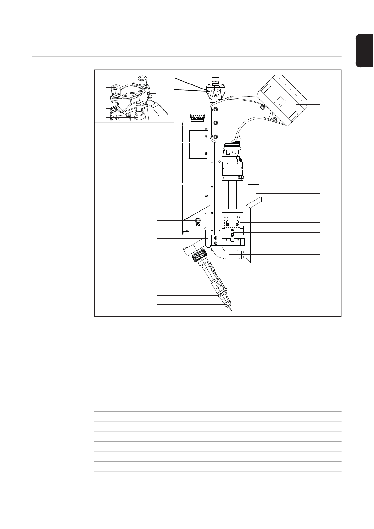
Device Description WF 25i LaserHybrid 10 kW
(1)
(2)
(3)
(4)
(6)
(8)
(9)
(10)
(11)
(2)
(3)
(5)
(7)
(15)
(16)
(17)
(18)
(19)
(20)
(12)
(13)
(14)
Item Description
(1) Exhaust for crossjet (must be connected to an extraction unit)
(2) Supply to crossjet
(3) Connection for optional pressure monitoring
A LaserHybrid hosepack with extra data line is needed for optional pressure monitoring.
Pressure is monitored in SplitBox SB 360i LaserHybrid (see page 35) for the laser
welding head and LaserHybrid hosepack.
(4) Supply to radial fan flow
(5) Supply to gas nozzle crossjet
(6) Fiber optic cable
(7) LaserHybrid hosepack connection
(8) Control box
(9) Drive unit cover
(21)
29
Page 30

Item Description
(1)
(2)
(3)
(4)
(5)
(6)
(7)
(8)
(14)
(13)
(12)
(11)
(9)
(8)
(10)
(10) Gas-test button
Wire-return button*
Wire-threading button*
* The wire-return and wire-threading buttons are located on the opposite side of the
laser welding head.
(11) Mounting plate
Thickness 21 mm or 17.5 mm, depending on application
(12) LaserHybrid welding torch
(13) Gas nozzle crossjet (optional)
(14) Gas nozzle
(15) Robot holder
(16) Bracket for robot connection
(17) Laser optics
(18) Extra extraction
(19) Laser optics water cooling connections
(20) Connection to radial air stream
(21) Crossjet
Device Description, SB 360i LaserHybrid
30
Back Front
Item Description
(1) (+) Current socket with fine thread
for connecting the power cable from the interconnecting hosepack
(2) Shielding gas connection socket
(3) SpeedNet connection
for connecting the SpeedNet cable from the interconnecting hosepack
(4) SpeedNet connection
(5) Gas purging connection
(6) Connection for welding torch cooling – coolant return flow (red)
for connecting system add-ons e.g. the remote control
for connecting the coolant return flow hose from the interconnecting hosepack
Page 31

Item Description
(7) Connection for welding torch cooling – coolant supply line (blue)
for connecting the coolant supply line hose from the interconnecting hosepack
(8) SplitBox SB 360i LaserHybrid mount
(9) Welding torch connection (FSC)
for connecting the LaserHybrid hosepack
(10)
(11)
(12) Connection crossjet IN
(13) Interconnecting hosepack (for the power source)
(14) Connecting plug for welding torch cooling
Connection crossjet OUT
not included in the SB 300i LaserHybrid in its original state; the interconnecting
hosepack is inserted into SB 300i LaserHybrid during the assembly.
for connecting the welding torch cooling on the LaserHybrid hosepack
EN-US
31
Page 32

Collision Protection
1
General The laser welding head is fitted with collision protection to protect the LaserHybrid welding
torch and the entire laser welding head.
The collision protection works on the floating contact principle. Displacing the welding torch
a certain amount will open the circuit (ring line) between the two inputs for the robot control.
The ring line runs from the laser welding head, via the LaserHybrid hosepack, on to the
SplitBox SB 360i LaserHybrid, and from there on to the connection for the robot interface
used on the power source.
Safety
The collision protection and its digital analysis are not a substitute for an electromechanical emergency stop protection device.
► Just like with collision protection, the emergency stop protection device also has to
Checking the Reference Point after
a Collision
Signal Analysis The signal from the collision protection is sent to the robot control via a robot interface.
IMPORTANT! After a collision, check the reference point as follows:
2
3
Further information can be found on page 95.
In the event of a collision, the ring line will open and the signal level will drop. The robot
control must carry out the following program sequence:
- Stop the laser and arc welding process immediately
- Stop the robot movement immediately
WARNING!
shut off the arc process and the laser process.
Set a 14 / 20 mm stick out on the LaserHybrid welding torch depending on the application and design
Move to reference point
Using the gauge, check the position of the wire electrode in relation to the focal point
in the x/y/z direction
32
Page 33

Connection Specifications
EN-US
Connection Specifications
(1)
(2)
(3)
(5)
(2)
(4)
(6)
(8)
(9)
(10)
(7)
Item Description
(1) Crossjet extraction connection
for connecting a hose in accordance with the following data:
- Internal diameter Di = 51 mm
- External diameter Da = 57 mm
- Max. length = 10 m
(2) Crossjet supply
for connecting a hose in accordance with the following data:
- Internal diameter Di = 12 mm
- External diameter Da = 14 mm
- Atmospheric overpressure in flow condition:
= 4.5 bar at both connections
p
min
- V
(3) Radial air supply
for connecting a hose in accordance with the following data:
- External diameter Da = 6 mm
The hose connects the radial air supply (3) to the radial air connection (10).
total = 1460 Nl/min
min
33
Page 34

Item Description
(4) Crossjet gas nozzle supply
for connecting a hose in accordance with the following data
- External diameter Da = 4 mm
The hose connects the crossjet gas nozzle supply (4) to the crossjet gas nozzle
(7).
(5) Fiber optic cable for laser
bending radius > 200 mm.
(6) LaserHybrid hosepack connection
MHP 360i LH/W/FSC/4.2 m
MHP 360i LH/W/FSC/7.5 m
(7) Gas nozzle crossjet
(8) Extra extraction connection
for connecting a hose in accordance with the following data:
- Internal diameter Di = 40 mm
- Extraction capacity required Q
- Atmospheric underpressure p
min
min
(9) Laser optics water cooling connection
(10) Connection to radial air stream
NOTE!
= 280 m³/h
= 21000 Pa
The welding torch and gas nozzle are also cooled down by the power source cooling
unit.
The optics are cooled down by the laser cooling unit.
► Never cool the laser optics with the power source cooling unit.
34
Page 35

Compressed Air
WF 25i LaserHybrid 10 kWSB 360i LaserHybrid
MHP LH
(1)
(2)
(3) (4)
(5)
(6)
(7)
(8)
Diagram
MPH LH = LaserHybrid hosepack
EN-US
(7)
Item Description
(1) Compressed air supply
(7)
(8)
(2) Solenoid valve
(min. 6 bar)
(3) Internal pressure measurement
(4) Pressure measurement option
(9)
(4)
(4)
(6)
(5) Radial air stream branching
(6) Gas nozzle crossjet branching
(7) Crossjet air supply duct connections
(8) Exhaust air crossjet
(5)
(9) Extraction
NOTE!
The "VALVE ON" signal for controlling the solenoid valve (2) is transmitted to bit 26 (start counting with
0).
Pressure Monitoring in the SplitBox SB 360i
LaserHybrid
The pressure is monitored after the solenoid valve.
If the pressure falls below 4.5 bar for longer than two seconds, the "Powersource Ready"
bit is withdrawn and error code 16835 (laser crossjet air pressure supply low) issued.
35
Page 36

36
Page 37

Commissioning
Page 38

Page 39

General
EN-US
Safety
Setup Regulations
WARNING!
Work performed incorrectly can cause serious injury and damage to property.
► This setting work must only be carried out by trained and qualified personnel.
► Observe the safety rules in the OI, in particular the "Safety Inspection" section.
The power sources have been tested according to protection class IP 23. This means:
- Protection against solid foreign bodies larger than Ø 12 mm (0.47 in.)
- Protection against spraywater up to an inclined angle of 60°
The welding system can be set up and operated outdoors in accordance with protection
class IP 23. However, the effects of direct moisture (e.g. from rain) must be avoided.
WARNING!
Toppling or falling devices can be deadly.
► Securely set up the devices on a level and stable surface.
The ventilation channel of the power sources is an important safety device. When selecting
the setup location, ensure that the cooling air can enter and exit unhindered through the
vents on the front and back. Any electrically conductive dust (e.g. from grinding work) must
not be allowed to be sucked directly into the system.
Grid Connection The device is designed for the grid voltage listed on the rating plate. The fuse protection
required for the grid lead can be found in the "Technical Data" section. If mains cables or
mains plugs are not included with your version of the appliance, attach the appropriate
mains cable or mains plug in accordance with your country's standards.
CAUTION!
An under-dimensioned electrical installation can lead to serious damage.
► The grid lead and its fuse protection should be designed to suit the existing power sup-
ply.
► The technical data on the rating plate should be followed.
39
Page 40

Set Up LaserHy-
2
5
8
9
12
15
18
19
22
brid Welding System
WARNING!
If a power source is connected to the grid during installation, there is a danger of
serious injury and damage.
Please read the information in the "Safety Rules" chapter in the Operating Instructions for
the power source before starting for the first time. Only perform all of the preparation steps
if
► the power switch for the power source is set to – O – ,
► the mains cable is disconnected from the grid.
Initial situation:
Robot and robot control are present and ready for operation
Set up welding system:
Install upright brackets
1
Install cooling unit on upright bracket
Connect power source to cooling unit
3
Set up welding wire drum
4
Assemble WF Mounting Drum on welding wire drum
Set up and connect wirefeeder reel
6
Connect power source to robot control
7
Connect remote control
Set up laser welding head:
Installing the Laser Welding Head on the Robot
Installing and Connecting SplitBox SB 360i LaserHybrid
10
Connect crossjet
11
Connecting LaserHybrid Hosepack to Laser Welding Head
Connecting/changing Wirefeeding Hose to/on Laser Welding Head
13
Installing/Changing Wirefeed Rollers
14
Connect laser optics and extra extraction
Preparing Welding Torch
16
Install LaserHybrid hosepack on robot
17
Threading the Wire Electrode
Other activities prior to start-up:
Setting up Laser Welding Head
Creating Reference Program
20
Signal sequence for LaserHybrid welding
21
Measures before starting welding
Set up ground earth connection between workpiece and power source
23
40
Page 41

Installing the Laser Welding Head on the Robot
1
Connection Options on the Robot
90 mm
406,5 mm
EN-US
Installing the Laser Welding Head
on the Robot
Install the laser welding head in line
1
with the robot manufacturer's specifications for the robot.
41
Page 42

Installing and Connecting SplitBox SB 360i LaserHy-
2
3
3
3
3
3
4
4
brid
Installing SplitBox SB 360i LaserHybrid on Robot
Separate the SplitBox SB 360i LaserHybrid and SplitBox mount
1
Install a suitable holder for the SplitBox mount on your robot
IMPORTANT Please observe the robot manufacturer's assembly instructions.
Fit the SplitBox mount on the holder
using 4 x Allen screws size 6 mm
Tightening torque = 24 Nm
Insert the interconnecting hosepack
strain-relief device into the opening
and push forward
42
Page 43

Fix the interconnecting hosepack
5
7
6
5
5
6
7
8
8
8
9
10
10
10
10
10
10
9
10
strain-relief device in place using 2 x
Allen screws size 4 mm
Open the ear clamps (x 2)
Insert the interconnecting hosepack
into the ear clamps
Close the ear clamps
EN-US
Insert SplitBox SB 360i LaserHybrid
into the SplitBox mount as illustrated
Fix SplitBox in place in the SplitBox
mount using 3 x screws TX25 at the top
and 3 x screws TX25 at the bottom
Tightening torque = 3.5 Nm
43
Page 44

Connecting Split-
a
*
b
c
d
e
f
1
3
2
4
2
3
4
6
5
5
6
Box SB 360i LaserHybrid
Connect interconnecting hosepack to
SplitBox:
a) Power cable
b) Welding torch cooling return flow
(red)
c) Welding torch cooling supply line
(blue)
d) Protective gas shield
e) SpeedNet (from interconnecting
hosepack)
f) SpeedNet (remote control)
* Gas purging connection
Connect LaserHybrid hosepack to welding torch connection (FSC)
Close clamping lever
Open cover on LaserHybrid hosepack
Connect connecting plug for welding
torch cooling to the LaserHybrid hosepack
Connect crossjet air inlet
44
Page 45

IMPORTANT! When connecting crossjet
7
8
7
8
7
8
9
9
9
9
9
(1)
air outlet hoses, make sure that cutting
rings are present!
Connect crossjet air outlet (x 2)
Fix the hoses in place on the connec-
tion using hexagon nuts size 24 mm
Tightening torque = 50 Nm
IMPORTANT! Use flat spanner size 22 mm
to hold the items in place when fixing the
hexagon nuts in place on the connection
Connect hoses for optics cooling
(push-in)
Blue marking = coolant supply line
EN-US
Connecting Interconnecting Hosepack to Power Source
10
Option:
(1) Data line 3 x 0.5 mm²
(e.g. for analyzing additional pressure monitoring)
45
Page 46

Connecting Crossjet
2
1
1
2
3
3
3
4
6
5
4
5
6
7
8
Connecting the
CrossJet
Insert CrossJet exhaust air hose into
the opening
Position fixing plate so that it is in a
groove of the CrossJet exhaust hose
(x2 - also on the opposite side)
Secure fixing plate with 2 Allen screws,
3 mm
(x2 - also on the opposite side)
46
Depending on the robot movement,
determine the required length of the air
hoses and cut the air hoses accordingly to size
Withdraw protective hose
IMPORTANT! When connecting the
CrossJet air outlet hoses, ensure that
the cutting rings are present!
Connect CrossJet air outlet
Secure hose to the connection using a
hexagonal nut, 24 mm
Tightening torque = 50 Nm
IMPORTANT! When securing the hexagon nut to the 22 mm connection socket, counter with a 22 mm wrench.
Repeat process on the other side
Page 47

Pull protective hoses over the connec-
8
8
9
tions
EN-US
47
Page 48

Connecting LaserHybrid Hosepack to Laser Welding
1
1
2
2
45,0200,1404
4
3
3
4
5
3
4
5
Head
Connecting LaserHybrid Hosepack
to Laser Welding
Head
IMPORTANT! When connecting the LaserHybrid hosepack, ensure that pins and connec-
tions on the interface do not get bent or damaged.
Align the LaserHybrid hosepack to be as straight as possible.
Connect the LaserHybrid hosepack
Fix the LaserHybrid hosepack in place:
Tighten the union nut using a torch key
and torque wrench
Tightening torque = 11 Nm
Remove 2 x Allen screws size 2.5 mm
Remove 2 x Allen screws size 2.5 mm
on the opposite side
Remove drive unit cover
48
Page 49

Put CrashBox cable together
7
6
6
6
7
1
1
3
2
4
5
2
3
4
5
1
2
Lay cable in groove
EN-US
Connecting/
changing Wirefeeding Hose to/
on Laser Welding
Head
Insert wirefeeding hose into laser welding head
Press and hold locking button
Insert the wirefeeding hose into the lo-
cking device as far as is needed to release the locking button
Release the locking button
Keep pushing the wirefeeding hose un-
til the locking device locks in place and
the locking button pops out
Removal:
Press and hold locking button
Pull wirefeeding hose out of locking de-
vice
49
Page 50

Installing/Changing Wirefeed Rollers
3
2
4
5
6
1
1
2
3
4
5
6
Installing/Changing Wirefeed Rollers
IMPORTANT! The wire electrode has to be pulled out in order to change the wirefeed roll-
er.
Disconnect external wirefeeding hose
Swing the clamping stirrup open
Remove the screwable shaft
Remove the wirefeeder roller
Remove the hexagon nut size 10 mm –
use the driving wheel key supplied with
the laser welding head to hold this on
the wirefeeder roller
Remove the wirefeeder roller
The sequence is reversed for installation
NOTE!
Do not replace the supplied wirefeeder components with other models.
Failure to use the specified V groove rollers in particular may cause problems during the
wirefeed.
50
Page 51

Connecting Laser Optics and Extra Extraction
1
1
5x
1
1
1
1
b
a
a
c
c
2
EN-US
Connecting Laser
Optics
CAUTION!
Risk of damage to the laser welding head as a result of contamination from above.
► Please observe the Operating Instructions, specifications and safety instructions is-
sued by the manufacturer of the laser optics
► Prior to connection, position the laser welding head so that the longitudinal axis on the
laser welding head is outside of the horizontal (> 90°). This will ensure that no dirt can
get into the laser optics from above.
Remove 5 x Allen screws size 6 mm
For assembly:
the 3 x shorter screws are located one below the other; the 2 x longer screws opposite each other.
Remove 2 x register pins:
a) Position and connect extractor
tool for register pins
b) Hit the vibrating mass on the ex-
tractor tool backward and then remove the register pins
c) Remove bracket for robot connec-
tion
51
Page 52

Position the laser welding head so that
3
4
5
4
5
7
6
6
7
the longitudinal axis on the laser welding head is outside of the horizontal (>
90°)
Clean connection area using compressed air
Remove protective cover from fiber optic cable connection
Clean fiber optic cable plug using compressed air
Remove protective cover from fiber optic cable plug
52
Page 53

IMPORTANT! When connecting the fiber
b
a
b
c
8
9
10
10
10
optic cable, pay attention to the position of
the register pin on the plug.
Connect fiber optic cable:
a) Press the key
b) Pull the rubber sleeve back in the
direction of the optics
c) Connect the fiber optic cable plug
Check whether the rubber sleeve is
sealing neatly around the fiber optic
cable plug
IMPORTANT The illustration shows an
incorrectly positioned rubber sleeve.
The rubber sleeve shown forms a kink
in the area around the arrow, which
means that it does not seal completely.
EN-US
INCORRECTLY positioned rubber sleeve!
The rubber sleeve does not seal completely.
Connect optics cooling using Allen
screw size 2.5 mm
Tightening torque = 4 Nm
53
Page 54

Connect optics cooling supply line
11
11
11
12
12
12
12
2
1
1
2
(blue marking)
Connect optics cooling return flow
Connecting Extra
Extraction
Put the laser welding head into a vertical position
13
Push the hose across the connection
Fix the hose in place with the hose
clamp
54
Page 55

Position bracket for robot connection
3
4
3
4
5
5
5
6
7
7
8
6
7
8
Push the slot nut up so that the top hole
on the slot nut is positioned below the
top hole on the bracket for the robot
connection.
Fasten, but do not completely tighten,
the slot nut and bracket for the robot
connection using a short Allen screw
size 6 mm
EN-US
Insert 2 x register pins
Position and connect extractor tool for
register pins
Hit the vibrating mass on the extractor
tool forward and then position the register pins
55
Page 56

For assembly:
5x
10
9
9
9
9
10
the 3 x shorter screws are located one below the other; the 2 x longer screws opposite each other.
Insert the remaining 4 x Allen screws
size 6 mm
Fix the bracket for the robot connection
in place using 5 x Allen screws size 6
mm
Tightening torque = 24 Nm
56
Page 57

Preparing Welding Torch
1
1
2
2
3
3
EN-US
Preparing Welding Torch
Open knurled nut
Insert the inner liner into the welding
torch from underneath
Use the entire contact tip to insert the
entire inner liner into the welding torch
57
Page 58

Place the union nut over the contact tip
4
5
4
5
8
6
7
6
7
8
9
9
Tighten union nut
size 12 mm
Tightening torque = 3 Nm
Put the gas nozzle in position
Fix the gas nozzle in position using Al-
len screw size 4 mm
Fold the bracket downward
Tighten the knurled nut
58
Page 59

Installing Hosepack on Robot
EN-US
Placing the Hosepack on the Robot
IMPORTANT! The optional LaserHybrid hosepack holder is not included in the scope of
supply for the laser welding head.
6 x 5 Nm
44,0360,0099
(11)
(13)
8 Nm
(14)
2,9 Nm
(12)
27 Nm
2,9 Nm
(12)
(8)
(5)
(7)
(6)
(6)
(9)
(10)
(11)
(6)
(6)
(7)
(4)
(4)
44,0350,0254
(1) Robot arm
(2) Mounting HP LH xx
(3) Item profile 10 50 x 50 mm, 2 m
(4) Optional extension arm
(5) Opening for extraction hose
(6) Opening for wirefeeding hose
(7) Opening for fiber optic cable
(8) Opening for LaserHybrid hose-
M10
45 Nm
Mounting plate depending on robot
(42,1000,0112)
(44,0350,0254)
pack
42,1000,0112
(3)
(2)
(1)
(9) Adapter insert for extraction hose
set, diameter 41/51 mm
(42,0411,9036)
(10) Lower sheet metal part
(11) Slot nut
(12) Allen screw
M4 x 60 mm
(13) Allen screw
M8 x 20 mm
(14) Allen screw
M6 x 25 mm
59
Page 60

Installation
3
4
7
10
Mount the mounting plate (2) to the robot arm (1) according to the instructions of the
1
robot manufacturer
Cut the profile 10 50 x 50 mm (3) to length according to the robot arm
2
Mount the profile 10 50 x 50 mm (3) using slot nuts and 4 hexagonal bolts, size 17 mm,
to the mounting plate (2)
Tightening torque = 10 Nm
Remove Allen screw, size 3 mm (12), and dismantle the lower sheet metal part (10)
of the LaserHybrid hosepack holder
Loosen the 2 Allen screws, size 6 mm (13), between the lower sheet metal part (10)
5
and the slot nut (11) so that the slot nut (11) can be pushed into the top slot on the
profile 10 50 x 50 mm (3)
Push the slot nut (11) with the lower sheet metal part (10) into the top slot on the profile
6
10 50 x 50 mm (3)
Tighten 2 Allen screws, size 6 mm (13), and secure the lower sheet metal part (10)
with the slot nut (11) to the profile 10 50 x 50 mm (3)
Tightening torque = 27 Nm
Repeat steps 4 - 7 for all LaserHybrid hosepack holders
8
Using the Allen screw, size 3 mm (12), attach the components of the LaserHybrid
9
hosepack holder(s) back onto the lower sheet metal part (10)
Tightening torque = 2.9 Nm
For all LaserHybrid hosepack holders, remove the top and side plastic parts
6 Allen screws, size 5 mm (14)
Position hoses, cables, and LaserHybrid hosepack into the openings of the LaserHy-
11
brid hosepack holders
For all LaserHybrid hosepack holders, fit the top plastic part and secure to the side
12
plastic parts
6 Allen screws, size 5 mm (14), tightening torque = 4 Nm
60
Page 61

Threading the Wire Electrode
2
1
1
2
3
3
3
EN-US
Threading the
Wire Electrode
IMPORTANT! Carefully deburr the end of the wire electrode before threading the wire on it.
Requirement:
- Wirefeeding hose connected
- Wire electrode threaded in wirefeeder reel
- Correct wirefeeder rollers and inlet nozzles present in laser welding head
Close clamping stirrup
Press the wire-threading button until
the wire electrode comes out of the
welding torch
Set contact pressure
61
Page 62

Setting up Laser Welding Head
(1)
(2) (3)
Stick Out There are two different mounting plates for the laser welding head, depending on the ap-
plication:
Mounting plate 21 mm Mounting plate 17.5 mm
- The TCP cannot be on the laser fo-
cus.
- For high outputs
- Guarantees a greater distance be-
tween the laser focus and the wire
electrode tip with the same adjustment travel
- The TCP can be on the laser focus,
depending on the application.
NOTE!
When adjusting the physical location of
the welding torch, ensure there is a correct stick out for any mounting plate present.
(1) Welding torch
(2) Contact tip
(3) Stick out
Mounting plate 17.5 mm:
Stick out = 14 mm
Mounting plate 21 mm:
Stick out = 20 mm
62
Page 63

Adjustable Axes The physical location of the arc process in relation to the laser beam can be adjusted on
y
z
x
three Cartesian coordinate axes:
CAUTION!
Risk of damage to the fiber optic when workpiece surface is positioned at a right angle to the laser welding head.
If the laser optics are at a 90° angle to the workpiece surface, the laser radiation is reflected
directly into the laser optics. This can cause serious damage to the fiber optic.
► The wirefeed to the laser welding head should always be leading or trailing.
EN-US
63
Page 64

Adjustment
(1)
(2)
(3)
(4)
(5)
(6)
Mechanisms on
the Laser Welding
Head
The laser welding is fitted with adjustment mechanisms that make it possible to achieve
exact positioning on the x, y and z coordinate axes:
(1) Scale for z-axis
(2) Adjusting screw with division for
x-axis
Adjustment range +/- 4.5 mm
Allen screw size 5 mm
¼ turn equates to adjustment travel
of 0.25 mm
(3) Adjusting screw with division for y-axis
Adjustment range +7 / -2 mm
Allen screw size 5 mm
¼ turn equates to adjustment travel of 0.25 mm
Reading accuracy using Nonius 0.1 mm
(4) Scale for y-axis
(5) Scale for additional adjustment option on the z-axis
Adjustment range 0 / +10 mm
Basic position for the Trumpf optics holder = 0
Loosen the 2 x Allen screws size 5 mm in order to make additional adjustments on
the z-axis and move the optics holder.
Tightening torque for the Allen screws = 10 Nm
(6) Adjusting screw with division for z-axis
Adjustment range +12 / -7 mm
Allen screw size 5 mm
¼ turn equates to adjustment travel of 0.25 mm
Reading accuracy using Nonius 0.1 mm
64
Page 65

Setting Up X-Axis
(1)
(1)
1
1
1
2
2
2
NOTE!
The x-axis and y-axis are set up with the cover removed from the drive unit.
► Re-fit the cover on the drive unit after set-up.
Loosen 2 x Allen screws size 5 mm (1)
Set up the x-axis using the adjusting
screw and Allen key size 5 mm:
1 x turn equates to 1.0 mm
EN-US
After setting up the x-axis, re-tighten the 2 x Allen screws size 5 mm (1)
3
65
Page 66

Setting Up Y-Axis
(1)(1)
1
1
1
2
2
2
NOTE!
The x-axis and y-axis are set up with the cover removed from the drive unit.
► Re-fit the cover on the drive unit after set-up.
Loosen 2 x Allen screws size 5 mm (1)
Set up the y-axis using the adjusting
screw and Allen key size 5 mm:
1 x turn equates to 1.0 mm
After setting up the y-axis, re-tighten the 2 x Allen screws size 5 mm (1)
3
66
Page 67

Setting Up Z-Axis
1
2
3
3
3
NOTE!
The z-axis is set up with the cover removed from the drive unit and with the control
box removed.
► Re-fit the drive unit after setting up the control box and cover.
Loosen 2 x Allen screws size 5 mm (1)
Loosen 2 x Allen screws size 5 mm (2)
2
(2)
(1)
2
1
1
(2)
(1)
EN-US
Set up the z-axis using the adjusting
screw and Allen key size 5 mm:
1 x turn equates to 1.0 mm
After setting up the z-axis, re-tighten the 4 x Allen screws size 5 mm (1) and (2):
1
Tightening torque for screw (1) = 6.5 Nm
Tightening torque for screw (2) = 10 Nm
67
Page 68

Creating Reference Program
1
y
x
r
z
(1)
(1)
y
4
5
6
Safety
Work performed incorrectly can cause serious injury and damage to property.
► This setting work must only be carried out by trained and qualified personnel.
► Observe the safety rules in the OI, in particular the "Safety Inspection" section.
General A pilot laser with low power is required for the described adjustment work.
A reference program will also need to be created:
- After the laser welding head is installed for the first time
- When programming a new part, if the x-, y- and z-values have changed on the adjust-
Creating Reference Program
A metal gauge for exact adjustment of the wire electrode position in relation to the laser
focus is included with the laser welding head as standard.
This gauge is installed in the robot's work area and is used to create a reference program
for the series parts.
Creating a Reference Program Before Welding the First Series Part
WARNING!
ment units.
Requirement:
- The laser welding head must be fully set up and have all its connections in place.
- The wire electrode must be threaded.
- Depending on the mounting plate present, the relevant stick out mm must be adjusted
for the wire electrode:
Mounting plate 21 mm ... Stick out = 20 mm
Mounting plate 17.5 mm ... Stick out = 14 mm
- Observe the focal distance specification on the laser optics
Fit the gauge (1) in the robot's work area
Switch on pilot laser
2
Position the laser welding head via the robot so that the laser optics are at a 90° angle
3
to the gauge
Presetting for identifying parameters for the
part to be welded:
Move the gauge with the robot so that
the laser focus is in the cross hair on
the gauge
Using the robot, lower the laser welding head so that the wire electrode is
touching the gauge
Position the wire electrode in relation
to the laser focus using the x- and y-adjustment units on the laser welding
head
Standard value:
r = 3 mm
68
Page 69

Document the distance from the wire electrode to the laser focus on the x- and y-axis
9
7
using the scaling on the gauge
Store the settings as a reference program in the robot
8
Carry out a test weld
The best welding results are used as a basis for the reference program.
If changes are required to the mechanical x/y settings because of the test weld, over-
10
write the first reference program you created
EN-US
69
Page 70

Signal Sequence for LaserHybrid Welding
2
1
Safety
WARNING!
Work performed incorrectly can cause serious injury and damage to property.
► The welding process may only be programmed by trained personnel.
► Observe the safety rules in the OI, in particular the "Safety Inspection" section
CAUTION!
Risk of damage to the optical fiber due to the laser welding head being perpendicular to the workpiece surface during welding.
If the laser optics unit is at 90° to the workpiece surface, then the laser beam is reflected
directly into the laser optics. This may cause serious damage to the optical fiber.
► Always guide the laser welding head to be trailing or leading!
NOTE!
When welding lots of short weld seams in direct succession, only switch off the
CrossJet flow and external extraction system at the end of the entire process.
This will avoid contamination of the protective glass due to welding fumes.
Signal Sequence
for LaserHybrid
Welding
Robot start position:
Set signal "Extraction on"
1
Set signal "Crossjet on"
NOTE!
The "VALVE ON" signal for controlling the solenoid valve in the SplitBox SB 360i
LaserHybrid is transmitted to bit 26 (start counting with 0).
If preheating is not required, continue from "LaserHybrid welding start position."
Preheating start position:
Requirement: The laser must be ready for beam release.
Set signal "Gas test"
Set signal "Laser on"
2
The following factors determine the preheating temperature:
Travel speed
Laser output
Distance to the workpiece surface
Preheating end position:
Reset signal "Laser on"
1
Reset signal "Gas test"
2
70
Page 71

LaserHybrid welding start position:
3
4
1
4
1
Requirement: The laser must be ready for beam release.
Set signal "Arc on"
1
Wait for the current flow signal ("arc standing")
2
Set signal "Laser on"
Set signal "Start robot"
LaserHybrid welding end position:
Stop robot movement
Reset signal "Laser on"
2
Reset signal "Welding on"
3
Wait until the current flow signal = zero
Robot end position:
IMPORTANT! The robot end position is not the end of the weld seam.
Reset signal "Crossjet on"
Reset signal "Extraction on"
2
EN-US
71
Page 72

Measures before Starting Welding
1
4
7
Measures before
Starting Welding
Check the coolant flow on the laser optics cooling system
Check the coolant flow on the welding torch cooling system
2
(visual inspection in the coolant tank of the cooling unit)
Check whether a protective glass is present in the laser optics
3
Check whether all covers are correctly mounted on the laser welding head
Test CrossJet
5
Test extraction
6
Test shielding gas
72
Page 73

Operation Recommendations for LaserHybrid Weld-
ing System
EN-US
Operation Recommendations
for LaserHybrid
Welding System
To ensure smooth operation, the following objects should always be available for a LaserHybrid welding system:
LaserHybrid service station
Compressed-air gun supplied with 6 bar
Movable tool trolley containing the following tools and spare parts:
- 20 x contact tips, for each diameter
- 10 x gas distributors
- 4 x gas nozzles
- 4 x welding torch inner liners (cut to length and finished)
- 1 x wirefeeder roller set incl. compression lever with axles
- Allen key set
- Side cutters
- Release spray
- Cleaning set optics from the respective optics manufacturer
- 1 x protective glass drawer, packed so that it is dustproof (as a spare)
- At least 10 x protective glass panes, packed so they are dustproof
IMPORTANT! Always keep one spare laser welding head (incl. optics) in storage.
- Delivery time for a new laser welding head:
- Delivery time for laser optics:
- Timeframe for laser optics repair:
min. 8 weeks
min. 8 weeks
min. 8 weeks
Specifications for
the compressedair supply
IMPORTANT! The external extraction must be switched on throughout the entire laser
welding head service.
To ensure the proper functioning of the device, fulfill the following specifications for the
compressed air supply:
- compressed air supply at least 7 bar constant
- compressed air free of oil
- compressed air free of water
- compressed air free of dust - no contaminants larger than 5µm
73
Page 74

74
Page 75

Maintenance
Page 76

Page 77

Replacing the Welding Torch and Welding Torch
2
1
1
2
3
1
2
3
Wearing Parts
EN-US
Safety
Welding Torch
Spare Parts
CAUTION!
Risk of burns due to the intensely heated welding torch during operation.
► The welding torch may only be cleaned, and its components checked, once it has
cooled down.
Replacing the
Welding Torch
Please note:
the numbering on the arrows in the illustrations may not match the work steps.
Remove 2 x Allen screws size 2.5 mm
Remove 2 x Allen screws size 2.5 mm
on the opposite side
Remove drive unit cover
77
Page 78

Open knurled nut
1
4
5
6
45,0200,1404
5
6
Loosen the union nut using the torch
key
Pull the welding torch down and off
NOTE!
The torch key and torque wrench (tightening torque = 18 +/- 2 Nm) must be used to
assemble the welding torch
78
Page 79

Replacing Weld-
1
2
1
2
ing Torch Wearing Parts
1 2
EN-US
4
2
3
1
3
3
1
IMPORTANT! Before assembly, clean the gas distributor, the thread on the union nut and
the torch body.
79
Page 80

Replacing the Spatter Guard Plate and Extra Ex-
11
10
10
1
2
13
12
12
1
2
3
traction
Replacing the
Spatter Guard
Plate
Replacing the Extra Extraction
Please note:
the numbering on the arrows in the illustrations may not match the work steps.
Remove 2 x Allen screws
size 2.5 mm
Remove spatter guard
Assemble by performing the steps in the reverse order
Please note:
the numbering on the arrows in the illustrations may not match the work steps.
Disassemble spatter guard plate
Remove 2 x Allen screws
size 2.5 mm
Remove extra extraction
Assemble by performing the steps in the reverse order
80
Page 81

Replacing the Laser Optics
1
1
5x
1
1
1
1
EN-US
Safety
Replacing the
Trumpf Laser Optics
Preparation
WARNING!
Work performed incorrectly can cause serious injury and damage to property.
► This assembly work must only be carried out by trained and qualified personnel.
► Observe the safety rules in the OI, in particular the "Safety Inspection" section.
We are using Trumpf laser optics to describe how to replace the laser optics.
Precitec and Highyag laser optics are replaced using the same procedure.
The differences between the individual optics are described in the "Laser Optics – Overview" section from page 94 onward.
CAUTION!
Risk of damage to the laser welding head as a result of contamination from above.
► Please observe the Operating Instructions, specifications and safety instructions is-
sued by the manufacturer of the laser optics
► Prior to removing the laser optics, position the laser welding head so that the longitu-
dinal axis on the laser welding head is outside of the horizontal (> 90°). This will ensure
that no dirt can get into the laser optics from above.
Please note:
the numbering on the arrows in the illustrations may not match the work steps.
Remove 5 x Allen screws size 6 mm
81
Page 82

Remove 2 x register pins:
b
a
a
c
c
2
3
6
6
6
8
a) Position and connect extractor
tool for register pins
b) Hit the vibrating mass on the ex-
tractor tool backward and then remove the register pins
Remove bracket for robot connection
Position the laser welding head so that the longitudinal axis on the laser welding head
4
is outside of the horizontal (> 90°)
Shut off the hose for the extra extraction
5
IMPORTANT! Only shut off the coolant
hose on the laser optics, never on the fiber
optic cable.
Loosen the Allen screw and shut off
the coolant hose from the laser optics
size 2.5 mm
To shut off the fiber optic cable from the laser optics, reverse the sequence used for connection; see page 51, work step 6 onward:
Clean the fiber optic cable and connection area with compressed air
7
Pull rubber sleeve back in direction of optics
Press button underneath
Disconnect fiber optic cable
Fit protective covers on fiber optic cable plug and fiber optic cable connection
82
Page 83

Disconnect radial air stream
9
9
11
10
10
10
11
13
12
12
12
13
Remove 2 x Allen screws
size 2.5 mm
Remove spatter guard
EN-US
Remove 2 x Allen screws
size 2.5 mm
Remove extra extraction
83
Page 84

Remove 4 x Allen screws
14
14
14
14
15
14
15
2
2
2
2
1
1
1
1
1
1
1
2
3
3
4
5
5
3
4
5
size 3 mm
Remove crossjet
IMPORTANT! When removing the crossjet,
make sure that the O-rings do not get lost.
Removing the Laser Optics
Remove 6 x threaded pins
size 2.5 mm
Remove 4 x Allen screws
size 4 mm
Remove 2 x Allen screws
size 4 mm
Remove fixing clamp
Loosen 2 x Allen screws
size 4 mm
84
Page 85

Loosen 2 x Allen screws
6
6
6
8
7
7
7
8
8
7
8
size 4 mm
CAUTION!
Dropping the laser optics may lead to
damage beyond repair.
► Remove and handle the laser optics ca-
refully.
EN-US
Push the laser optics out from the
guide and holder
Remove the laser optics
IMPORTANT! When removing the laser
optics, make sure that the springs connected underneath do not get lost.
The springs will be needed again for installation.
85
Page 86

Inserting the La-
1
2
2
1
2
4
3
4
4
3
4
ser Optics
IMPORTANT! When replacing the laser optics, ensure that the laser optics and welding
torch are compatible in terms of the focal length.
CAUTION!
Dropping the laser optics may lead to
damage beyond repair.
► Insert and handle the laser optics care-
fully.
Remove 2 x springs from the removed
laser optics and insert into the new laser optics
IMPORTANT! When inserting the new laser optics, ensure that the installation position is correct:
- The plug on the fiber optic cable, coolant hoses and protective glass drawer must all be accessible,
- the push-button must be up.
Insert the laser optics so that the
springs are underneath in the grooves
Press the laser optics at the rear end
down
Move the laser optics into the holder
and into the guide
86
Page 87

Insert 4 x Allen screws
5
6
5
5
5
5
6
9
8
8
7
7
8
9
10
10
Tighten the Allen screws slightly
size 4 mm
Fit fixing clamp
Insert 2 x Allen screws
Tighten the Allen screws slightly
size 4 mm
EN-US
Connect the fiber optic cable on the laser optics
see page 51, work step 2 onward
87
Page 88

Position the laser welding head via the
90°
13
13
11
12
14
13
(1)
(2)
11
12
13
14
15
robot so that the laser optics are at a
90° angle to the reference gauge
Connect radial air stream
Connect coolant hose (1):
- to LaserHybrid hosepack
- to laser optics
Connect coolant hose (2) to laser optics
Check/adjust laser optics focus as described in the following section
88
Page 89

Checking/Adjust-
2
y
x
r
z
(1)
(1)
y
1
1
1
1
5
ing Laser Optics
Focus
After replacing Trumpf laser optics, check the focus and, if necessary, adjust it, in order to
even out any optic tolerances.
A pilot laser with low power is required for the described adjustment work.
Checking Laser Optics Focus
Depending on the mounting plate present, adjust the relevant stick out for the wire
1
electrode:
Mounting plate 21 mm ... Stick out = 20 mm
Mounting plate 17.5 mm ... Stick out = 14 mm
Switch on pilot laser
Upload reference program
3
Move gauge (1)
4
If the pilot laser's focus is in the cross hair
on the gauge (1), you do not need to adjust
the focus.
If the focus is different from the intersection
point on the cross hair, adjust the focus on
the laser optics as follows:
EN-US
Adjusting Laser Optics Focus
Loosen 4 x Allen screws
size 4 mm
89
Page 90

Set up focus in y direction:
(1)
(2)
(3)
6
7
8
9
10
12
10
10
10
10
1
Using the Allen screw threaded pins
(2), set up the laser optics in the y direction
size 2.5 mm
The installed springs take care of the +/
- movement.
Screw the Allen screw threaded pins
(1) and (3) tight
size 2.5 mm
Set up focus in positive x direction:
Loosen Allen screw threaded pins (1)
by two turns
Using the Allen screw threaded pins
(3), set up the laser optics in the positive x-direction
size 2.5 mm
Screw the Allen screw threaded pins
(1) tight
size 2.5 mm
Set up focus in negative x direction:
Loosen Allen screw threaded pins (3)
11
by two turns
Using the Allen screw threaded pins
(1), set up the laser optics in the negative x-direction
size 2.5 mm
Screw the Allen screw threaded pins
13
(3) tight
size 2.5 mm
Tighten 4 x Allen screws
size 4 mm
Tightening torque = 3.8 Nm
90
Page 91

Fixing the Laser
2x
1
1
2
1
2
3
3
3
2x
4
4
Optics
NOTE!
To prevent the laser optics from warping on the laser head, ensure you perform the
following work steps in the exact same sequence.
Set up terminal
Tighten 2 x Allen screws
size 4 mm
Tightening torque = 5.7 Nm
Screw fixing clamp tight with 2 x Allen
screws
size 4 mm
Tightening torque = 3.8 Nm
EN-US
Tighten 2 x Allen screws
size 4 mm
Tightening torque = 3.8 Nm
91
Page 92

Final Tasks IMPORTANT! Check the laser optics' focus before assembling the crossjet.
1
1
1
1
1
2
2
2
3
3
3
IMPORTANT! When installing the crossjet,
make sure that the O-rings are present.
Install the crossjet with 4 x Allen
screws
size 3 mm
Tightening torque = 2.5 Nm
Install the extra extraction with 2 x Allen screws
size 2.5 mm
Tightening torque = 1 Nm
Assemble spatter guard plate with 2 x
Allen screws
size 2.5 mm
92
Page 93

Position bracket for robot connection
3
4
4
5
5
5
6
6
7
7
8
7
8
9
Push the slot nut up so that the top hole
on the slot nut is positioned below the
top hole on the bracket for the robot
connection.
Fasten, but do not completely tighten,
the slot nut and bracket for the robot
connection using an Allen screw size
6 mm
EN-US
Insert 2 x register pins
Position and connect extractor tool for
register pins
Hit the vibrating mass on the extractor
tool forward and then position the register pins
93
Page 94

Laser Optics –
5x
10
9
9
9
10
11
Overview
Insert the remaining 4 x Allen screws
size 6 mm
Fix the bracket for the robot connection
in place using 5 x Allen screws size 6
mm
Tightening torque = 24 Nm
PRECITEC HIGHYAGTRUMPF
+ 4,101,078 * + 4,100,714 * + 4,101,068 *
**
4x M5 x 16 mm
4x M5 x 16 mm
2x M5 x 25 mm
4x M5 x 12 mm
2x M5 x 16 mm
2x M4 x 12 mm
4x M5 x 12 mm
4x M5 x 16 mm
* Optics holder
** 2nd bracket for robot connection hidden
94
Page 95

Checking Position of the Wire Electrode in relation
2
y
x
r
z
(1)
(1)
y
4
5
6
7
to the Laser Focus
EN-US
Safety
Work performed incorrectly can cause serious injury and damage to property.
► This setting work must only be carried out by trained and qualified personnel.
► Observe the safety rules in the OI, in particular the "Safety Inspection" section.
General A pilot laser with low power is required for the described adjustment work.
Check the position of the wire electrode in relation to the laser focus:
- Each time the laser welding head is replaced
- Each time the laser optics are replaced
- Each time the welding torch is changed
Checking Position of the Wire
Electrode in relation to the Laser
Focus
1
3
WARNING!
Switch off MIG/MAG power source
Replace components
Switch on MIG/MAG power source
Using the robot, move to the reference
point on the gauge (1):
the laser focus is in the cross hair on
the gauge
Thread the wire electrodes up to the
gauge
Check the position of the wire electrode in relation to the laser focus:
The position of the wire electrode must
match the values documented on the
gauge using scaling.
If necessary, correct the position of the
wire electrode in relation to the laser
focus using the x- and y-adjustment
mechanisms
95
Page 96

Example: Refer-
2
5
8
ence Program Application after
Welding Torch
Change
Switch off power source
1
Change welding torch
After the welding torch has been changed and the wearing parts have been fitted:
3
switch on power source
Set the stick out to either 14 or 20 mm, depending on the application
4
Upload the reference program and slowly move to the reference position on the adjusting gauge
Thread the wire electrode until this is touching the adjusting gauge
6
Check the position of the wire electrode in relation to the laser focus
7
If the position is incorrect:
Adjust the x/y position on the mechanical setting options for the laser welding head –
NOT on the robot
IMPORTANT Never overwrite the robot's reference program.
Production begins
9
96
Page 97

Measures to Reduce Contamination of the Optics
EN-US
Measures to Reduce Contamination of the Optics
Crossjet and Extraction
1. Please observe the values for the crossjet and extraction specified in these Operating
Instructions.
2. Switch on the crossjet and extraction at least five seconds before the start of welding.
3. Do not switch off the crossjet and extraction until the laser welding head is safely in
the smoke-free zone.
Protective Glass (including Replacement)
IMPORTANT! Before changing the protective glass drawer, clean the area around it with
a cleaning cloth.
The environment must be clean when the protective glass drawer is being replaced.
4. To prevent dust from penetrating the focusing lens, the laser welding head must be
vertical when the protective glass is being changed (welding torch pointing toward the
floor).
5. Before changing the protective glass:
– Switch on the extraction and crossjet
– Clean the welding head with compressed air as best as you can
IMPORTANT Do not blast the protective glass with the air current directly.
– Switch off crossjet
– Replace protective glass
IMPORTANT When replacing the protective glass, the extraction must be
switched on and crossjet switched off.
6. Keep the amount of time the protective glass drawer is open to the minimum necessary.
7. If there are welding fumes on the protective glass, replace the protective glass with a
new pane of glass.
The contaminated protective glass can be used again:
– Pre-clean the protective glass with a cloth
– Finish cleaning the protective glass with a cotton swab soaked in methanol
– Store the protective glass in a dust-free area
8. If there is welding spatter on the protective glass, the protective glass must be replaced with a new pane of glass immediately.
Dispose of the protective glass that has welding spatter.
9. Check the protective glass from time to time at the start of production in order to determine a change interval specific to the application.
Automated Torch Cleaning Device
10. When using an automatic torch cleaning device:
Switch on the crossjet and extraction during the cleaning process.
97
Page 98

Changing the Fiber Optic Cable
11. The laser welding head must be in a horizontal position when you are changing the
fiber optic cable so that no dust can fall into the optics from above.
IMPORTANT! Clean with compressed air before changing.
98
Page 99

Appendix
Page 100

 Loading...