

Operating
Instructions
WF 25i Dual
EN-US
Operating instructions
42,0426,0427,EA 001-03022023


Table of contents
Safety Instructions 6
General 6
Intended Use 6
Environmental Conditions 7
Obligations of the Operating Company 7
Obligations of Personnel 7
Grid Connection 7
Personal Protection and Protection of Others 7
Danger from toxic gases and vapors 8
Danger from Flying Sparks 9
Risks from grid current and welding current 9
Stray welding currents 10
EMC Device Classifications 10
EMC measures 11
EMF measures 11
Particular hazard areas 11
Requirement for the shielding gas 13
Danger from Shielding Gas Cylinders 13
Danger Posed by Shielding Gas Leak 13
Safety Measures at the Setup Location and During Transport 14
Safety Measures in Normal Operation 14
Maintenance and repair 15
Safety Inspection 15
Disposal 15
Safety symbols 16
Data backup 16
Copyright 16
General 17
Device concept 17
System requirements 17
Warning notices on the device 18
Description of the warnings on the device 20
Options and components 22
Options and components 22
Trolley options 24
System configurations 25
Setup on the trolley 25
Setup on the welding boom (Welding-Boom) 26
Setup on the crane 27
System limits 28
Crane transport 29
Crane transport safety sticker 29
Crane transport of the WF 25i Dual with D300 spool holder 30
Crane transport of the WF 25i Dual with D450 spool holder without spool cover 30
Crane transport of the WF 25i Dual mounted on the trolley 31
Operating controls, connections and mechanical components 32
Safety 32
WF 25i Dual with D300 spool holder 32
WF 25i Dual with D450 spool holder 34
Wirefeeder rear 36
Wirefeeder side 37
Function of the gas-test, wire-return, and wire-threading buttons 38
Before installation and initial operation 40
Safety 40
Intended use 40
Setup regulations 41
Installing Optional Equipment 42
Safety 42
Mounting the D300 spool holder with cover 42
Mounting the D450 spool holder without cover 43
EN-US
3

Mounting the crane transport option 44
Mounting the hosepack holder option 44
Mounting the tool tray option 45
Mounting the boom mounting kit option 45
Connecting the wirefeeder to the power source 46
Safety 46
General 46
Connecting the wirefeeder to the power source 46
Connecting the extension hosepack 48
Connecting the welding torch 50
Safety 50
Connecting a MIG/MAG welding torch 50
Inserting/changing feed rollers 52
Safety 52
General 52
Inserting/changing feed rollers 52
Remounting the D450 brake for operation with a D300 wirespool 54
Remounting the D450 brake for operation with a D300 wirespool 54
Inserting the wirespool/basket-type spool 55
Safety 55
Inserting the D300 wirespool 55
Inserting the D300 basket-type spool 56
Inserting the D450 wirespool 58
Threading the Wire Electrode 59
General 59
Preparation 59
Threading the wire electrode 60
Setting the contact pressure 61
Adjusting the brake 62
General 62
Adjusting the D300 brake 62
Design of the D300 brake 63
Adjusting the brake on the WF 25i Dual D450 63
Design of the D450 brake 65
Commissioning 66
Safety 66
Warning of electrically live (hot), exposed parts on WF 25i Dual with spool holder D450
without spool cover
Requirements for commissioning 67
Commissioning 67
Note for TIG AC applications 67
Selecting the welding process line 68
Selecting the weldingprocess line 68
Selecting thewelding process line using the torch trigger 68
Selecting thewelding process line using the button/LED on the wirefeeder 68
Selecting thewelding process line using the gas-test, wire-return, and wire-threading buttons
Selecting the welding process line on the power source or using RC Panel Pro remote
control
Selecting thewelding process line using the RC Panel Standard remote control 69
Troubleshooting 70
Safety 70
Troubleshooting 70
Service, maintenance and disposal 74
General 74
Safety 74
At every start-up 74
Every 6 months 74
Disposal 75
Technical data 76
WF 25i Dual 76
D300 spool holder with cover 77
D450 spool holder without cover 77
HP 70i 77
66
69
69
4

HP 95i 77
EN-US
5

Safety Instructions
General The device has been manufactured using state-of-the-art technology and ac-
cording to recognized safety standards. If used incorrectly or misused, however,
it can cause
Injury or death to the operator or a third party
-
Damage to the device and other material assets belonging to the operating
-
company
Inefficient operation of the equipment
-
All persons involved in the commissioning, operation, maintenance, and servicing
of the device must
Be suitably qualified
-
Have knowledge of welding
-
Have completely read and followed these Operating Instructions
-
The Operating Instructions must always be at hand wherever the device is being
used. In addition to the Operating Instructions, all applicable local rules and regulations regarding accident prevention and environmental protection must also
be followed.
All safety and danger notices on the device must
Be kept in a legible state
-
Not be damaged/marked
-
Not be removed
-
Not be covered, pasted, or painted over
-
For the location of the safety and danger notices on the device, refer to the section headed "General" in the Operating Instructions for the device.
Before switching on the device, remove any faults that could compromise safety.
Your personal safety is at stake!
Intended Use The device is to be used exclusively for its intended purpose.
The device is intended exclusively for the welding process specified on the rating
plate.
Utilization for any other purpose, or in any other manner, shall be deemed to be
"not in accordance with the intended purpose." The manufacturer is not responsible for any damage resulting from improper use.
Proper use also means
Completely reading and obeying all instructions in the Operating Instruc-
-
tions
Completely reading and obeying all safety instructions and danger notices
-
Carrying out all the specified inspection and servicing work
-
Never use the device for the following applications:
Thawing pipes
-
Charging batteries
-
Starting motors
-
The device is designed for operation in industry and business. The manufacture
shall not be liable for any damage resulting from use in a living area.
The manufacture shall also not be liable for faulty or incorrect work results.
6

Environmental
Conditions
Operation or storage of the device outside the stipulated area will be deemed as
not in accordance with the intended purpose. The manufacturer accepts no liability for any damage resulting from improper use.
Temperature range of the ambient air:
During operation: -10°C to +40°C (14°F to 104°F)
-
During transport and storage: -20°C to +55°C (-4°F to 131°F)
-
Relative humidity:
Up to 50% at 40°C (104°F)
-
Up to 90% at 20°C (68°F)
-
Ambient air: free of dust, acids, corrosive gases or substances, etc.
Altitude above sea level: up to 2000 m (6561 ft. 8.16 in.)
EN-US
Obligations of
the Operating
Company
The operating company must only allow persons to work with the device if they
Are familiar with the basic occupational safety and accident prevention regu-
-
lations and are trained in handling the device
Have read and understood these Operating Instructions, especially the sec-
-
tion "Safety Rules," and have confirmed this with their signature
Are trained according to the requirements for the work results
-
The safety-conscious work of the personnel must be checked regularly.
Obligations of
Personnel
All persons who are assigned to work with the device must do the following before beginning the work:
Follow the basic regulations for occupational safety and accident prevention
-
Read these Operating Instructions, especially the section "Safety Rules," and
-
confirm that they have understood and will follow them by signing
Before leaving the workplace, ensure that no personal injury or property damage
can occur in one's absence.
Grid Connection Devices with a high output can influence the energy quality of the grid due to
their current consumption.
Personal Protection and Protection of Others
This may affect a number of device types in terms of:
connection restrictions
-
-
criteria regarding maximum permissible grid impedance
-
criteria regarding the minimum required short-circuit power
*)
both at the interface with the public grid
*)
*)
See technical data
In this case, the operator or the person using the device should check whether or
not the device is allowed to be connected, where appropriate through discussion
with the power supply company.
IMPORTANT! Ensure secure grounding of the grid connection!
You are exposed to numerous hazards while handling the device, for example:
Flying sparks and pieces of hot metal
-
Arc radiation that poses a risk of injury to the eyes and skin
-
7

Hazardous electromagnetic fields that pose a risk of death for individuals
-
with pacemakers
Electrical risks from grid current and welding current
-
Increased noise exposure
-
Harmful welding fumes and gases
-
Wear suitable protective clothing when dealing with the device. The protective
clothing must have the following properties:
Flame resistant
-
Insulating and dry
-
Covering the entire body and in good condition with no damage
-
Safety helmet
-
Cuffless pants
-
Protective clothing involves the following:
Protecting the face and eyes from UV radiation, heat and flying sparks with a
-
face guard featuring a regulation-compliant filter
Wearing regulation-compliant protective goggles with side protection behind
-
the face guard
Wearing rigid, wet-insulating footwear
-
Protecting hands with appropriate gloves (featuring electrical insulation and
-
thermal protection)
Wearing ear protection to reduce noise exposure and protect against injury
-
Keep persons, especially children, away during the operation of the devices and
during the welding process. If persons are in the vicinity, however:
Instruct them about all hazards (blinding hazard due to arcs, risk of injury
-
from flying sparks, welding fumes hazardous to health, noise exposure, possible hazard due to grid current or welding current, etc.)
Provide suitable protective equipment or
-
Construct suitable protective walls and curtains.
-
Danger from toxic gases and vapors
The fumes produced during welding contain toxic gases and vapors.
Welding fumes contain substances that cause cancer, as stated in monograph
118 from the International Agency for Research on Cancer.
Use at-source extraction source and a room extraction system.
If possible, use a welding torch with an integrated extraction device.
Keep your head out of the welding fumes and gases.
Take the following precautionary measures for fumes and harmful gases:
Do not breathe them in.
-
Extract them from the work area using appropriate equipment.
-
Ensure that there is a sufficient supply of fresh air. Ensure that there is a ventilation flow rate of at least 20 m³ per hour.
Use a welding helmet with air supply if there is insufficient ventilation.
If there is uncertainty as to whether the extraction capacity is sufficient, compare the measured toxic emission values against the permissible limit values.
The following components are factors that determine how toxic the welding
fumes are:
The metals used for the workpiece
-
Electrodes
-
Coatings
-
Cleaning agents, degreasers, and the like
-
The welding process used
-
8

Consult the corresponding material safety data sheets and manufacturer's instructions for the components listed above.
Danger from Flying Sparks
Recommendations for exposure scenarios, risk management measures and
identifying working conditions can be found on the European Welding Association website under Health & Safety (https://european-welding.org).
Keep flammable vapors (such as solvent vapors) out of the arc radiation range.
When no welding is taking place, close the valve of the shielding gas cylinder or
the main gas supply.
Flying sparks can cause fires and explosions.
Never undertake welding near flammable materials.
Flammable materials must be kept at least 11 meters (36 ft. 1.07 in.) from the
arc or protected with a certified cover.
Keep suitable, tested fire extinguishers on hand.
Sparks and pieces of hot metal may also get into surrounding areas through
small cracks and openings. Take appropriate measures to ensure that there is no
risk of injury or fire.
Do not undertake welding in areas at risk of fire and explosion, or on sealed
tanks, drums, or pipes if these have not been prepared in accordance with corresponding national and international standards.
EN-US
Risks from grid
current and
welding current
Do not undertake welding on containers in which gases, fuels, mineral oils, and
the like are/were stored. Residues pose a risk of explosion.
An electric shock can be fatal.
Do not touch voltage-carrying parts inside or outside the device.
During MIG/MAG welding and TIG welding, the welding wire, the wirespool, the
feed rollers, as well as all pieces of metal that are in contact with the welding
wire, are live.
Always place the wirefeeder on a sufficiently insulated base or use a suitable insulating wirefeeder holder.
Ensure suitable personal protection with dry temporary backing or cover with
sufficient insulation against the ground potential. The temporary backing or cover must completely cover the entire area between the body and the ground potential.
All cables and leads must be secured, undamaged, insulated, and adequately dimensioned. Replace loose connections and scorched, damaged, or inadequately
dimensioned cables and leads immediately.
Before every use, check power connections for secure fit by hand.
In the case of power cables with bayonet connectors, turn the power cable by at
least 180° around the longitudinal axis and pretension.
Do not wrap cables or leads around your body or parts of the body.
Concerning the electrode (rod electrode, tungsten electrode, welding wire, etc.)
Never immerse it in liquids to cool it
-
Never touch it when the power source is switched on.
-
9

The open circuit voltage of a welding system may double, for example, between
the electrodes of two welding systems. Touching the potentials of both electrodes at the same time may be life-threatening in some cases.
Have the grid and device supply lead regularly inspected by an electrician to ensure that the ground conductor is functioning properly.
Protection class I devices require a grid with a ground conductor and a connector
system with ground conductor contact for proper operation.
Operation of the device on a grid without a ground conductor and on a socket
without a ground conductor contact is only permitted if all national regulations
for protective separation are observed.
Otherwise, this is considered gross negligence. The manufacturer accepts no liability for any damage resulting from improper use.
Use suitable equipment to ensure that the workpiece is sufficiently grounded if
necessary.
Switch off unused devices.
When working at elevated heights, wear a safety harness to prevent falls.
Before working on the device, switch off the device and remove the grid plug.
Secure the device to prevent the grid plug from being connected and switched
on again by applying a clearly legible and understandable warning sign.
Stray welding
currents
After opening the device:
Discharge all electrically charged components
-
Ensure that all components are disconnected from the power supply.
-
If work is needed on voltage-carrying parts, bring in a second person who will
switch off the main switch at the correct time.
If the following instructions are not observed, stray welding currents may occur,
which pose a risk of the following:
Fire
-
Overheating of parts connected to the workpiece
-
Irreparable damage to ground conductors
-
Damage to the device and other electrical equipment
-
Ensure that the workpiece clamp is securely connected to the workpiece.
Secure the workpiece clamp as close to the spot to be welded as possible.
Position the device with sufficient insulation against electrically conductive environments, e.g., insulation against electrically conductive floors or electrically conductive mounts.
Observe the following when using power distribution boards, twin-head mounts,
etc.: Even the electrode of the welding torch/electrode holder not in use carries
electric potential. Ensure that there is sufficient insulation when the unused
welding torch/electrode holder is stored.
EMC Device
Classifications
10
In automated MIG/MAG applications, only guide the wire electrode from the
welding wire drum, large spool, or wirespool to the wirefeeder with insulation.
Devices in emission class A:
Are only designed for use in industrial settings
-
Can cause line-bound and radiated interference in other areas
-

Devices in emission class B:
Satisfy the emissions criteria for residential and industrial areas. This is also
-
true for residential areas in which the energy is supplied from the public lowvoltage grid.
EMC device classification as per the rating plate or technical data.
EMC measures In certain cases, even though a device complies with the standard limit values for
emissions, it may affect the application area for which it was designed (e.g., when
there is sensitive equipment at the same location, or if the site where the device
is installed is close to either radio or television receivers).
If this is the case, then the operating company is obliged to take appropriate action to rectify the situation.
Test and assess the immunity of equipment in the vicinity of the device in accordance with national and international provisions. Examples of interferenceprone equipment that could be affected by the device:
Safety devices
-
Grid power lines, signal lines, and data transfer lines
-
IT and telecommunications equipment
-
Devices for measuring and calibrating
-
Supporting measures to avoid EMC problems:
Grid power supply
1.
If electromagnetic interference occurs despite a grid connection that
-
complies with regulations, take additional measures (e.g., use a suitable
grid filter).
Welding power-leads
2.
Keep them as short as possible
-
Route them close together (also to avoid EMF problems)
-
Route them far from other lines
-
Equipotential bonding
3.
Workpiece grounding
4.
If necessary, establish grounding using suitable capacitors.
-
Shield, if necessary
5.
Shield other devices in the vicinity
-
Shield the entire welding installation
-
EN-US
EMF measures Electromagnetic fields may cause health problems that are not yet known:
Effects on the health of persons close by, e.g., those with pacemakers and
-
hearing aids
Persons with pacemakers must seek advice from their doctor before staying
-
in the immediate vicinity of the device and the welding process
Keep distances between welding power-leads and the head/torso of the
-
welder as great as possible for safety reasons
Do not carry welding power-leads and hosepacks over your shoulder or wrap
-
them around your body or body parts
Particular hazard areas
Keep hands, hair, loose clothing, and tools away from moving parts, such as:
Fans
-
Gears
-
Rollers
-
Shafts
-
Wirespools and welding wires
-
11

Do not reach into rotating gears of the wire drive or into rotating drive parts.
Covers and side panels must only be opened/removed during maintenance and
repair work.
During operation
Ensure that all covers are closed, and all side parts have been mounted prop-
-
erly.
Keep all covers and side parts closed.
-
The protrusion of welding wire from the welding torch represents a high risk of
injury (cuts to the hand, facial and eye injuries, etc.).
Therefore, always hold the welding torch away from the body (devices with
wirefeeder) and use suitable protective goggles.
Do not touch the workpiece during or after welding – risk of burns.
Slag may fly off cooling workpieces. Therefore, also wear regulation-compliant
protective equipment when reworking workpieces and ensure that other persons
are sufficiently protected.
Leave the welding torch and other parts with a high operating temperature to
cool before working on them.
Special regulations apply in areas at risk of fire or explosion
– follow the appropriate national and international regulations.
Power sources for work in areas with increased electrical hazard (e.g., boilers)
must be labeled with the symbol (Safety). However, the power source may not be
located in such areas.
Risk of scalding due to leaking coolant. Switch off the cooling unit before disconnecting connections for the coolant supply or return.
When handling coolant, observe the information on the coolant safety data
sheet. The coolant safety data sheet can be obtained from your service center or
via the manufacturer's website.
Only use suitable load-carrying equipment from the manufacturer to transport
devices by crane.
Attach chains or ropes to all designated attachments of the suitable load-
-
carrying equipment.
Chains or ropes must be the smallest angle possible from vertical.
-
Remove gas cylinder and wirefeeder (MIG/MAG and TIG devices).
-
In the event of crane attachment of the wirefeeder during welding, always use a
suitable, insulating wirefeeder hoisting attachment (MIG/MAG and TIG devices).
If the device is equipped with a carrier belt or handle, then this is used exclusively for transport by hand. The carrier belt is not suitable for transport by crane,
counterbalanced lift truck, or other mechanical lifting tools.
All lifting equipment (belts, buckles, chains, etc.), which is used in association
with the device or its components, must be checked regularly (e.g., for mechanical damage, corrosion, or changes due to other environmental influences).
The test interval and scope must at least comply with the respective valid national standards and guidelines.
12
There is a risk of colorless, odorless shielding gas escaping without notice if an
adapter is used for the shielding gas connection. Use suitable Teflon tape to seal
the thread of the shielding gas connection adapter on the device side before installation.

Requirement for
the shielding gas
Especially with ring lines, contaminated shielding gas can cause damage to
equipment and reduce welding quality.
Meet the following requirements regarding shielding gas quality:
Solid particle size < 40 µm
-
Pressure condensation point < -20 °C
-
Max. oil content < 25 mg/m³
-
Use filters if necessary.
EN-US
Danger from
Shielding Gas
Cylinders
Shielding gas cylinders contain compressed gas and may explode if damaged.
Shielding gas cylinders are an integral part of the welding equipment, so they
must be handled very carefully.
Protect shielding gas cylinders with compressed gas from excessive heat, mechanical impact, slag, open flames, sparks, and arcs.
Mount the shielding gas cylinders vertically and secure them in accordance with
instructions so they cannot fall over.
Keep shielding gas cylinders away from welding or other electrical circuits.
Never hang a welding torch on a shielding gas cylinder.
Never touch a shielding gas cylinder with an electrode.
Risk of explosion: Never weld on a compressed shielding gas cylinder.
Always use suitable shielding gas cylinders for the application in question and the
correct matching accessories (controller, hoses, and fittings, etc.) Only use
shielding gas cylinders and accessories that are in good condition.
If a valve on a shielding gas cylinder is open, turn your face away from the outlet.
When no welding is taking place, close the valve of the shielding gas cylinder.
Leave the cap on the valve of the shielding gas cylinder when the cylinder is not
connected.
Danger Posed by
Shielding Gas
Leak
Follow the manufacturer's instructions and applicable national and international
provisions for shielding gas cylinders and accessories.
Risk of asphyxiation due to uncontrolled shielding gas leak
Shielding gas is colorless and odorless and may suppress the oxygen in the ambient air in the event of leakage.
Ensure there is a sufficient supply of fresh air with a ventilation flow rate of
-
at least 20 m³ per hour.
Please observe the safety and maintenance information for the shielding gas
-
cylinder or the main gas supply.
When no welding is taking place, close the valve of the shielding gas cylinder
-
or the main gas supply.
Always check the shielding gas cylinder or main gas supply for uncontrolled
-
gas leakage before each start-up.
13

Safety Measures
at the Setup
Location and
During Transport
A toppling device can be deadly! Set up the device securely on an even, solid surface
The maximum permitted tilt angle is 10°.
-
Special regulations apply in areas at risk of fire or explosion
Follow the appropriate national and international regulations.
-
Use instructions and checks within the company to ensure that the vicinity of the
workplace is always clean and organized.
Only set up and operate the device in accordance with the protection class
shown on the rating plate.
When setting up the device, ensure that there is an all-round clearance of 0.5 m
(1 ft. 7.69 in.) to allow cooling air to circulate unhindered.
Take care to ensure that the applicable national and regional guidelines and accident prevention regulations are observed when transporting the device, especially guidelines concerning hazards during transport and shipment.
Do not lift or transport any active devices. Switch off devices before transport or
lifting.
Before transporting the device, completely drain the coolant and dismantle the
following components:
wirefeeder
-
wirespool
-
shielding gas cylinder
-
Safety Measures
in Normal Operation
It is essential to conduct a visual inspection of the device to check for damage
after it has been transported but before commissioning. Have any damage repaired by trained service technicians before commissioning the device.
Only operate the device when all safety devices are fully functional. If the safety
devices are not fully functional, there is a danger of:
Injury or death to the operator or a third party
-
Damage to the device and other material assets belonging to the operating
-
company
Inefficient operation of the device
-
Safety devices that are not fully functional must be repaired before the device is
switched on.
Never bypass or disable safety devices.
Before switching on the device, ensure that no one can be put in danger.
The device must be examined at least once a week for externally detectable damage and functionality of the safety devices.
Always secure the shielding gas cylinder well and remove before transporting by
crane.
14
Only the original coolant from the manufacturer is suitable for use in our devices
due to its properties (electrical conductivity, anti-freeze, material compatibility,
flammability, etc.)
Only use appropriate original coolant from the manufacturer.
Do not mix original coolant from the manufacturer with other coolants.

Only connect system components from the manufacturer to the cooling unit circuit.
Maintenance and
repair
If there is damage due to use of other system components or other coolants, the
manufacturer accepts no liability for this and all warranty claims are forfeited.
Cooling Liquid FCL 10/20 is not flammable. The ethanol-based coolant is flam-
mable in certain conditions. Only transport the coolant in closed original containers and keep away from sources of ignition.
Properly dispose of used coolant according to national and international regulations. The coolant safety data sheet can be obtained from your service center or
via the manufacturer’s website.
When the system is cool, always check the coolant level before starting welding.
It is impossible to guarantee that bought-in parts are designed and manufactured to meet the demands made of them, or that they satisfy safety requirements.
Use only original spare and wearing parts (also applies to standard parts).
-
Do not carry out any modifications, alterations, etc. to the device without the
-
manufacturer's consent.
Components that are not in perfect condition must be replaced immediately.
-
When ordering, please give the exact designation and part number as shown
-
in the spare parts list, as well as the serial number of your device.
The housing screws provide the ground conductor connection for earthing the
housing parts.
Only use original housing screws in the correct number and tightened to the specified torque.
EN-US
Safety Inspection
Disposal Waste electrical and electronic equipment must be collected separately and re-
The manufacturer recommends that a safety inspection of the device be performed at least every 12 months.
The manufacturer recommends calibrating power sources within the same 12month interval.
A safety inspection by a certified electrician is recommended:
After changes
-
After alterations
-
After repair, care, and maintenance
-
At least every 12 months
-
For the safety inspection, follow the appropriate national and international
standards and guidelines.
You can obtain more information about the safety inspection and calibration
from your service center. The service center will provide the necessary documents upon request.
cycled in an environmentally sound manner in accordance with the European Directive and national law. Used equipment must be returned to the distributor or
through a local authorized collection and disposal system. Proper disposal of the
used device promotes sustainable recycling of material resources. Failure to observe this may lead to potential health/environmental impacts.
15

Packaging materials
Separate collection. Check your municipality’s regulations. Reduce the volume of
the box.
Safety symbols Devices with the CE label satisfy the essential requirements of the low-voltage
and electromagnetic compatibility directive (e.g., relevant product standards of
the EN 60974 series).
Fronius International GmbH declares that the device complies with Directive
2014/53/EU. The full text of the EU Declaration of Conformity is available on the
following website: http://www.fronius.com
Devices marked with the CSA test mark satisfy the requirements of the relevant
standards for Canada and the USA.
Data backup The user is responsible for backing up any changes made to the factory settings.
The manufacturer accepts no liability for any deleted personal settings.
Copyright Copyright of these Operating Instructions remains with the manufacturer.
Text and illustrations were accurate at the time of printing. Fronius reserves the
right to make changes. The contents of the Operating Instructions shall not
provide the basis for any claims whatsoever on the part of the purchaser. If you
have any suggestions for improvement, or can point out any mistakes that you
have found in the Operating Instructions, we will be most grateful for your comments.
16

General
Device concept The WF 25i Dual enables the joint use of two welding process lines with one
power source. The welding process lines can be changed using the torch trigger,
on the power source, via the operating controls on the wirefeeder, or on a remote
control.
Two spool holders and different options are available for the WF 25i Dual:
EN-US
System requirements
WF 25i Dual with D300 spool holder and spool
cover
for D300 mm wirespools
(with the Trabant, remote control, tool tray,
crane transport, and hosepack holder options)
WF 25i Dual with D450 spool holder without
spool cover
for large D450 mm spools
(with the Trabant, remote control, tool tray, and
crane transport options)
In order for the WF 25i Dual dual-head wirefeeder to work properly, the power
source must have the following firmware version:
official_TPSi_iWave_3.5.2-xxx.ffw or higher
17

Warning notices
40,0006,3035
WF 25i D300
WF 25i D450
ELECTRIC SHOCK can kill.
Wire, wire reel and drive rolls are electrically live (hot)
for ALL welding processes even when not in use!
Les CHOCS ELECTRIQUES peuvent tuer.
Le fil, la bobine de fil et les rouleaux d'entraînement sont
électriquement sous tension (chauds) pour TOUS les
procédés de soudage, même lorsqu'ils ne sont pas utilisés!
Las descargas eléctricas pueden ser mortales.
El alambre, el carrete de alambre y los rodillos impulsores
están eléctricamente vivos (calientes) para TODOS los
procesos de soldadura, incluso cuando no están en uso!
ADVERTENCIA
WARNING
ADVERTISSEMENT
inside
2x
inside
2x
on the device
The wirefeeder has safety symbols and a rating plate fitted. These safety symbols
and the rating plate must not be removed or painted over. The safety symbols
warn against operating the equipment incorrectly, as this may result in serious injury and damage to property.
Do not use the functions described here until you have fully read and
understood the following documents:
These Operating Instructions
-
All system component Operating Instructions, especially the
-
safety rules
Welding is dangerous. To ensure that this device can be used cor-
rectly and safely, the following basic requirements must be met:
Adequate welding qualifications
-
Appropriate protective equipment
-
Keep unauthorized people away from the wirefeeder and the
-
welding process
Dispose of old devices in accordance with safety rules and not in nor-
mal domestic waste.
18
Keep hands, hair, loose clothing, and tools away from moving parts,
ELECTRIC SHOCK can kill.
Wire, wire reel and drive rolls are electrically live (hot)
for ALL welding processes even when not in use!
Les CHOCS ELECTRIQUES peuvent tuer.
Le fil, la bobine de fil et les rouleaux d'entraînement sont
électriquement sous tension (chauds) pour TOUS les
procédés de soudage, même lorsqu'ils ne sont pas utilisés!
Las descargas eléctricas pueden ser mortales.
El alambre, el carrete de alambre y los rodillos impulsores
están eléctricamente vivos (calientes) para TODOS los
procesos de soldadura, incluso cuando no están en uso!
ADVERTENCIA
WARNING
ADVERTISSEMENT
such as:
Gears
-
Feed rollers
-
Wirespools and wire electrodes
-
Do not reach into rotating gears of the wire drive or into rotating
drive parts.
Covers and side panels must only be opened/removed during maintenance and repair work.
During operation
Ensure that all covers are closed, and all side parts have been
-
mounted properly.
Keep all covers and side parts closed.
-
An electric shock can be fatal!
Do not touch any exposed live parts!
Also see page 66!
EN-US
19

Description of
A B
the warnings on
the device
Warning notices are attached to the device for certain device versions.
The arrangement of the symbols may vary.
! Warning! Caution!
The symbols represent possible dangers.
A Drive rollers can injure fingers.
B The welding wire and drive parts are under welding voltage during opera-
tion.
Keep hands and metal objects away!
1. An electric shock can be fatal.
1.1 Wear dry, insulating gloves. Do not touch the wire electrode with bare
hands. Do not wear wet or damaged gloves.
1.2 Use a base that is insulated from the floor and work area to protect
against electric shock.
1.3 Before working on the device, switch off the device and remove the mains
plug or disconnect the power supply.
2. Inhalation of welding fumes can be harmful to health.
2.1 Keep your face away from any welding fumes.
20

2.2 Use forced-air ventilation or local extraction to remove welding fumes.
xx,xxxx,xxxx *
2.3 Remove welding fumes with a fan.
3. Welding sparks can cause an explosion or fire.
3.1 Keep flammable materials away from the welding process. Do not perform
welding near flammable materials.
3.2 Welding sparks can cause a fire. Have fire extinguishers ready. If neces-
sary, have a supervisor ready who can operate the fire extinguisher.
3.3 Do not weld on drums or closed containers.
EN-US
4. Arc rays can burn the eyes and injure the skin.
4.1 Wear headgear and protective goggles. Use ear protection and wear a
shirt collar with button. Use a welding helmet with the correct tinting.
Wear suitable protective clothing over the entire body.
5. Before working on the machine or welding:
undertake training on the device and read the instructions!
6. Do not remove or paint over the sticker with the warnings.
* Manufacturer order number of the sticker
21

Options and components
(1)
(2)
(4)
(5) (6)
(7)
(8)
(9)
(3)
(10)
Options and
components
(1) Crane transport option
OPT/WF Lift Bail Dual
(2) Tool tray option
OPT/WF Tool Tray Dual
(3) Hosepack holder option
Two-part, only in conjunction with D300 spool holder with cover
OPT/WF Hosepack Holder Dual
(4) D300 spool holder with cover
OPT/WF Spool Holder D300 Dual
(5) Dual-head wirefeeder
WF 25i Dual No Spool /4R/G/FSC
(6) Remote control option
RC Panel Standard, RC Panel Pro
(7) Coolant connections option
OPT/WF Water Connection Dual
22

(8) D450 spool holder without cover
OPT/WF Spool Holder D450 Dual
(without wirespools)
(9) Trabant trolley option
OPT/TU Trabant
(10) Boom mounting kit option
OPT/WF Boom Mounting Kit Dual
Not pictured:
Euro connection conversion kit
-
SpeedNet cable 5 m
-
SpeedNet cable 10 m
-
EN-US
23
Trolley options
(1)
(2)
(a)
(b)
(c)
(d)
(1) TU Car 4 Pro trolley
incl. gas cylinder holder
(2) WF Dual mounting set option
OPT/TU Mounting Set WF Dual
incl.:
Storage vessel
a)
Tubular frame
b)
2 x insulated torch holder
c)
Second gas cylinder holder and cylinder strap
d)
Mounting material
24

System configurations
EN-US
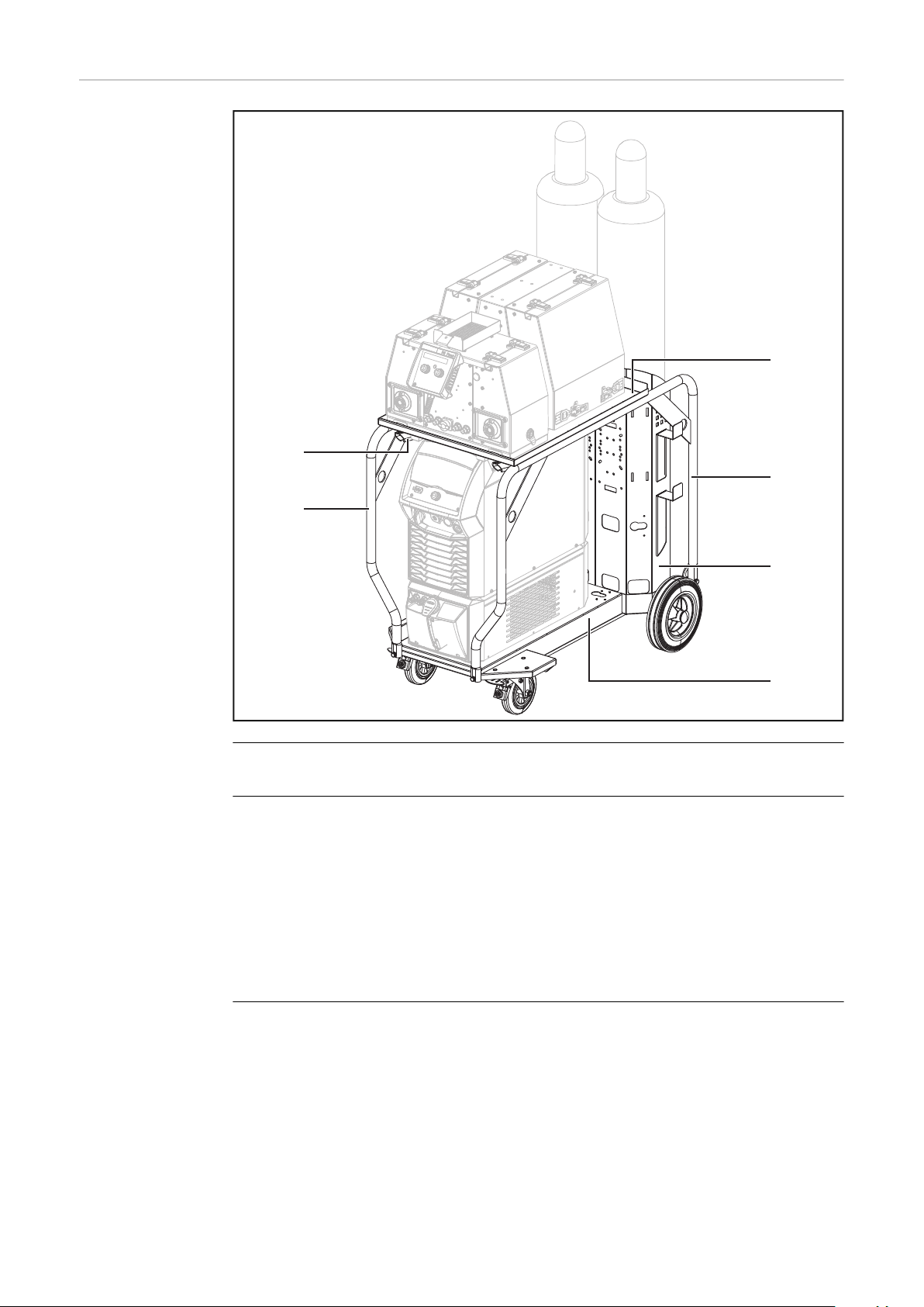
Setup on the
trolley
Required for setup on the trolley:
TU Car 4 Pro trolley
-
OPT/TU Mounting Set WF Dual H510 option (for gas-cooled systems)
-
or
OPT/TU Mounting Set WF Dual H740 option (for water-cooled systems)
WF 25i Dual with D300 spool holder on the trolley
An alternative setup on the trolley could include the WF 25i Dual with D450
spool holder.
Details on setting up the dual-head wirefeeder on the trolley can be found in the
"OPT/TU Mounting Set WF Dual" Installation Instructions (42,0410,2636).
25
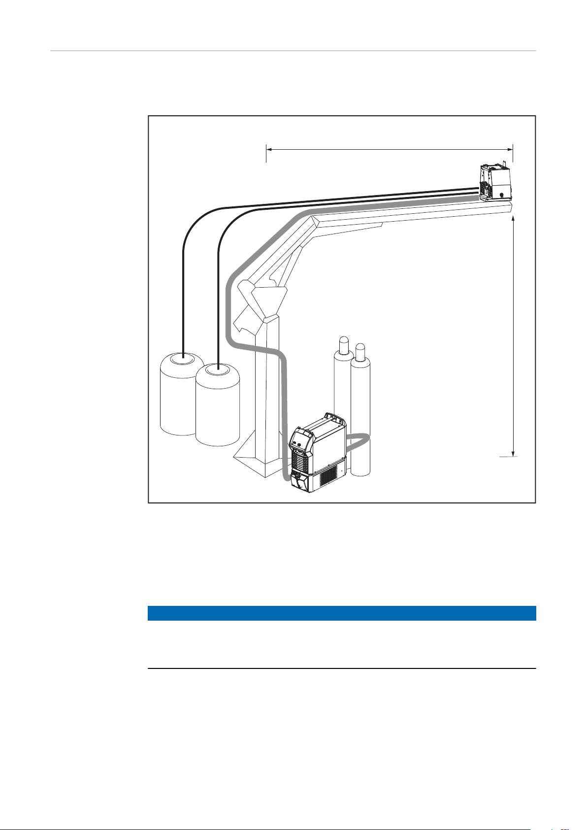
Setup on the
max. 5 m / 16 ft. 4.85 in.
max.
3 m
9 ft. 10.11 in.
welding boom
(Welding-Boom)
The OPT/WF Boom Mounting Kit Dual option is required for setup on the welding
boom.
The use of welding wire drums is recommended.
WF 25i Dual with boom mounting kit option, mounted on the welding boom (schematic presentation)
Max. delivery head 3 m / 9 ft. 10.11 in.
Max. conveying length, horizontal 5 m / 16 ft. 4.85 in.
Max. conveying distance, welding wire
drum to welding torch
NOTE!
The dual-head wirefeeder must be installed on the welding boom in such a way
that it is insulated.
Use boom mounting kit option or equivalent insulation.
▶
16 m / 52 ft. 5.92 in.
26

Setup on the
crane
The OPT/WF Lift Bail Dual option is required for setup on the crane.
EN-US
WF 25i Dual with D300 spool holder for crane setup
IMPORTANT! Setup and operation on the crane are only permitted for the WF
25i Dual with D300 spool holder.
NOTE!
For crane applications, select the suspension position of the dual-head
wirefeeder so that it hangs as horizontally as possible on the crane.
Observe details on crane transport (from page 29).
▶
27

System limits Depending on the welding system, the following data must be observed for wa-
ter-cooled system components.
Welding system with WF 25i Dual and TPS 320i - 600i (MIG/MAG):
Suitable cooling units CU 1100i, CU 1100i /MV RVP,
CU 1400i Pro
Interconnecting hosepack * Max. 25 m / 82 ft. 0.25 in.
Torch hosepack 2 x max. 6 m / 19 ft. 8.22 in.
Welding system with WF 25i Dual and iWave 300i - 500i MP (MIG/MAG + TIG):
Suitable cooling units CU 1400i Pro
Interconnecting hosepack * Max. 25 m / 82 ft. 0.25 in.
MIG/MAG torch hosepack 2 x max. 6 m / 19 ft. 8.22 in.
TIG torch
hosepack **
IMPORTANT! A water-cooled TIG extension hosepack cannot be used in conjunction with a WF 25i Dual.
* Connection from the power source to the wirefeeder
** For multiprocess welding systems, if a water-cooled TIG welding torch is
connected in addition to the 2 water-cooled MIG/MAG welding torches.
Max. 8 m / 26 ft. 2.96 in.
28
Crane transport
42,0409,1255
EN-US
Crane transport
safety sticker
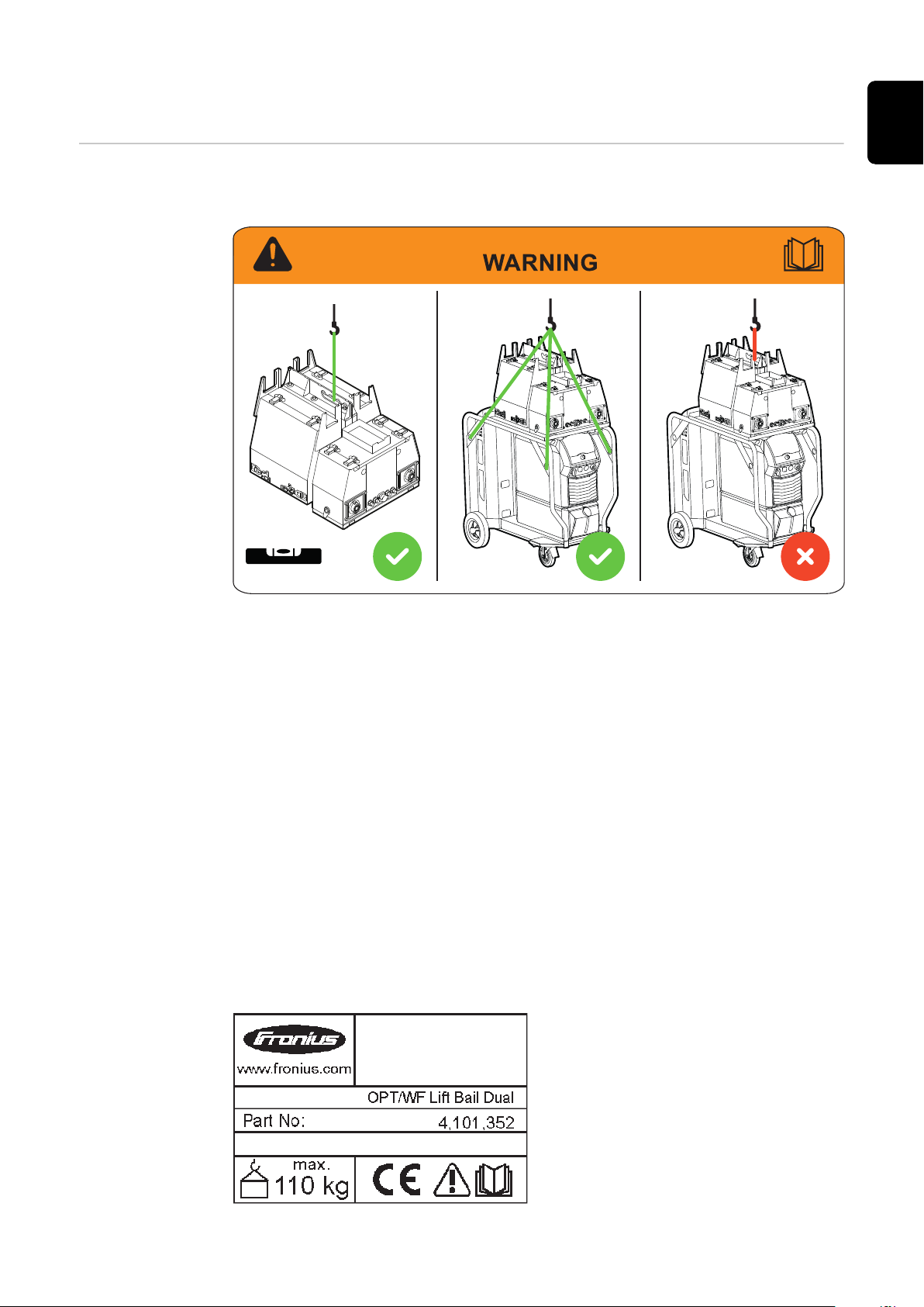
The following safety sticker is attached to the crane transport option OPT/WF
Lift Bail Dual:
a) b) c)
The WF 25i Dual may only be transported with the OPT/WF Lift Bail Dual op-
a)
tion mounted on the crane.
For details, see page 30.
Crane transport of a welding system mounted on the trolley with WF 25i
b)
Dual is only permitted in conjunction with the OPT/TU Mounting Set WF
Dual option.
For details, see page 31.
Crane transport of a welding system mounted on the trolley with WF 25i
c)
Dual on the crane transport option OPT/WF Lift Bail Dual is not permitted.
For details, see page 31 or the Installation Instructions for the OPT/TU
Mounting Set WF Dual option (42,0410,2636).
The crane transport option OPT/WF Lift Bail Dual also has a rating plate indicating the maximum load capacity:
29

Crane transport
of the WF 25i
Dual with D300
spool holder
The OPT/WF Lift Bail Dual crane transport option is required for crane transport
of the WF 25i Dual with D300 spool holder.
WARNING!
Danger from falling objects.
This can result in serious personal injury and damage to property.
Ensure that the crane transport option has been mounted correctly accord-
▶
ing to the specifications in these Operating Instructions and taking into account all torque specifications.
Ensure that the wirespools/basket-type spools, including basket-type spool
▶
adapters, are always firmly seated on the wirespool holders.
Ensure that the side parts of the spool holder are closed and secured during
▶
crane transport.
Only transport the wirefeeder using the crane transport option.
▶
For crane transport, use only tested lifting equipment that complies with na-
▶
tional guidelines.
Select the suspension position of the dual-head wirefeeder so that it hangs
▶
as horizontally as possible on the crane.
Crane transport
of the WF 25i
Dual with D450
spool holder
without spool
cover
The OPT/WF Lift Bail Dual crane transport option is required for crane transport
of the WF 25i Dual with D450 spool holder without spool cover.
WARNING!
Danger from falling objects.
This can result in serious personal injury and damage to property.
Ensure that the crane transport option has been mounted correctly accord-
▶
ing to the specifications in these Operating Instructions and taking into account all torque specifications.
Before transporting by crane, remove the wirespools/basket-type spools, in-
▶
cluding the basket-type spool adapters, from the wirespool holders.
Only transport the wirefeeder using the crane transport option.
▶
For crane transport, use only tested lifting equipment that complies with na-
▶
tional guidelines.
Select the suspension position of the dual-head wirefeeder so that it hangs
▶
as horizontally as possible on the crane.
30

Crane transport
of the WF 25i
Dual mounted on
the trolley
The WF Dual mounting set trolley option is required for crane transport of the
welding system mounted on the trolley.
WARNING!
Danger from falling objects.
This can result in serious personal injury and damage to property.
Ensure that the welding system and the WF Dual mounting set option are
▶
correctly mounted on the trolley.
Before transporting by crane, remove the gas cylinders from the trolley.
▶
For the WF 25i Dual with D300 spool holder, ensure that
▶
a) the wirespools/basket-type spools, including basket-type spool adapters,
are firmly seated on the wirespool holders;
b) the side parts of the spool holder are closed and secured during crane
transport.
For the WF 25i Dual with D450 spool holder without spool cover, remove the
▶
wirespools before transporting by crane.
Transport the welding system on the trolley only at the marked positions.
▶
Always attach the lifting equipment to all four suspension points.
▶
For crane transport, use only tested lifting equipment that complies with na-
▶
tional guidelines.
Details on crane transport can be found in the Installation Instructions for the
OPT/TU Mounting Set WF Dual (42,0410,2636) option.
EN-US
31

Operating controls, connections and mechanical
(1)
(2)
(3)
(4)
(5)
(6)
(7)
(16)
(15)
(14)
(13)
(12)
(11)
(10)
(8)
(9)
components
Safety
WF 25i Dual with
D300 spool holder
WARNING!
Danger from incorrect operation and work that is not carried out properly.
This can result in serious personal injury and damage to property.
All the work and functions described in this document must only be carried
▶
out by technically trained and qualified personnel.
Read and understand this document in full.
▶
Read and understand all safety rules and user documentation for this equip-
▶
ment and all system components.
(1) Crane transport option
OPT/WF Lift Bail Dual
For transport by crane
The wirespools can remain in the wirefeeder if the side parts of the spool
holder are closed and secured.
32

For use on the crane
The wirefeeder hangs on the crane during welding work, the wirespools
are in the wirefeeder, the side parts of the spool holder are closed and secured.
(Also see System configurations/Setup on the crane from page 27)
(2) Tool tray option
OPT/WF Tool Tray Dual
(3) Remote control holder
(4) Welding line 1 button/LED
To activate welding line 1
The LED lights up when the welding line is active.
(5) Remote control option
RC Panel Standard, RC Panel Pro
(6) Welding torch connection
Welding process line 1
(7) Coolant supply connection (blue) *
Option
Welding process line 1
EN-US
(8) Coolant return connection (red) *
Option
Welding process line 1
(9) SpeedNet connection
For connecting the remote control
(10) Coolant supply connection (blue) *
Option
Welding process line 2
(11) Coolant return connection (red) *
Option
Welding process line 2
(12) Trabant trolley option
OPT/TU Trabant
(13) Welding torch connection
Welding process line 2
(14) Welding line 2 button/LED
To activate welding line 2
The LED lights up when the welding line is active.
(15) Wirespool cover
both sides
(16) Hosepack holder
* If the coolant hoses of one welding torch are terminated, the other weld-
ing torch is also no longer supplied with coolant.
In this case, use the enclosed, short cooling hose piece for bridging.
33

WF 25i Dual with
(1)
(2)
(3)
(4)
(5)
(6)
(7)
(8)
(14)
(13)
(12)
(10) (11)
(9)
D450 spool holder
(1) Crane transport option
OPT/WF Lift Bail Dual
For transport by crane
The wirespools must be removed for transport by crane.
(2) Tool tray option
OPT/WF Tool Tray Dual
(3) Remote control holder
(4) Welding line 1 button/LED
To activate welding line 1
The LED lights up when the welding line is active.
(5) Remote control option
RC Panel Standard, RC Panel Pro
(6) Welding torch connection
Welding process line 1
(7) Coolant supply connection (blue) *
Option
Welding process line 1
34

(8) Coolant return connection (red) *
Option
Welding process line 1
(9) SpeedNet connection
For connecting the remote control
(10) Coolant supply connection (blue) *
Option
Welding process line 2
(11) Coolant return connection (red) *
Option
Welding process line 2
(12) Trabant trolley option
OPT/TU Trabant
(13) Welding torch connection
Welding process line 2
(14) Welding line 2 button/LED
To activate welding line 2
The LED lights up when the welding line is active.
EN-US
The wirespools are not included in the scope of supply.
* If the coolant hoses of one welding torch are terminated, the other weld-
ing torch is also no longer supplied with coolant.
In this case, use the enclosed, short cooling hose piece for bridging.
35

Wirefeeder rear
(1) (1)(2) (3) (4) (5) (6)
(7) (8)
(9)
WF 25i Dual + D300
WF 25i Dual + D450
(1) Strain-relief device for the interconnecting hosepack
(2) Wire infeed tube
Welding process line 2
(3) Coolant return connection (red)
Option
For connecting the coolant return hose from the interconnecting hosepack
(4) Power connection
For connecting the power cable from the interconnecting hosepack
(5) Coolant supply connection (blue)
Option
For connecting the coolant supply hose from the interconnecting hosepack
(6) Wire infeed tube
Welding process line 1
(7) Shielding gas connection
Welding process line 2
(8) SpeedNet connection
For connecting the SpeedNet cable from the interconnecting hosepack
(9) Shielding gas connection
Welding process line 1
36

Wirefeeder side
(1)
(2)
(2)
(3) (4) (5) (6)
(7)
(8)
(9)
WF 25i Dual + D300
WF 25i Dual + D450
EN-US
Illustration without covers and side parts shown
(1) Basket-type spool adapter
(2) Wirespool holder with brake
(3) Operating status LED
Lights up green when the device is ready for operation
(4) Gas-test button
(5) Wire-return button
(6) Wire-threading button
(7) Clamping lever
For adjusting the contact pressure of the feed rollers
(8) 4-roller drive
(9) Clamping lever
The described elements are located on both sides of the wirefeeder.
37

Function of the
gas-test, wirereturn, and wirethreading buttons
Operating status LED
Lights up green when the device is ready for operation
Gas-test button
After pressing the gas-test button, gas is released for 30 s. Pressing the button
again will end the process prematurely.
Wire-return button
There are two options available for retracting the wire electrode:
Option 1
Withdraw wire electrode at the preset wire return speed:
Press and hold the wire-return button
-
After pressing the wire-return button, the wire electrode is retracted by
-
1 mm (0.039 in.)
After a brief pause, the wirefeeder continues retracting the wire electrode –
-
if the wire-return button is kept pressed down, then the speed increases with
each further second by 10 m/min (393.70 ipm) until the preset wire-return
speed is reached
Option 2
Withdraw wire electrode in 1 mm steps (0.039 in. steps)
Always press (touch) the wire-return button for less than 1 second
-
NOTE!
Only retract the wire electrode a small amount at a time, to avoid the wire electrode becoming entangled on the wirespool during retraction.
NOTE!
If there is a ground earth connection with the contact tip, before the wire-return button is pressed, the wire electrode is retracted by pressing the wire-return button until the wire electrode is short-circuit-free—however, this must
not exceed 10 mm (0.39 in.) each time the button is pressed.
If the wire electrode needs to be retracted further, press the wire-return button
again.
Wire-threading button
There are two options available for the wire threading:
Option 1
Thread the wire electrode at the preset feeder inching speed:
Press and hold the wire-threading button
-
After pressing the wire-threading button, the wire electrode will be threaded
-
in by 1 mm (0.039 in.)
After a brief pause, the wirefeeder continues threading in the wire electrode
-
– if the wire-threading button is kept pressed down, then the speed increases with each further second by 10 m/min (393.70 ipm) until the preset
feeder inching speed is reached
If the wire electrode meets a ground earth connection, then the wirefeeding
-
is stopped and the wire electrode is retracted again by 1 mm (0.039 in.)
38

Option 2
Thread the wire electrode in 1 mm steps (0.039 in. steps)
Always press (touch) the wire-threading button for less than 1 second
-
If the wire electrode meets a ground earth connection, then the wirefeeding
-
is stopped and the wire electrode is retracted again by 1 mm (0.039 in.)
NOTE!
If there is a ground earth connection with the contact tip, before the wirethreading button is pressed, the wire electrode is retracted by pressing the wirethreading button until the wire electrode is short-circuit-free—however, this
must not exceed 10 mm (0.39 in.) each time the button is pressed.
If after the 10 mm (0.39 in.) wire retraction there is still a ground earth connection with the contact tip, then when the wire-threading button is pressed again,
the wire electrode is retracted again by a maximum of 10 mm (0.39 in.). The process is repeated until there is no longer any ground earth connection with the
contact tip.
EN-US
39

Before installation and initial operation
Safety
Danger from incorrect operation and work that is not carried out properly.
This can result in serious personal injury and damage to property.
▶
▶
▶
Intended use The device is intended exclusively for end of wirefeeding with MIG/MAG welding
in combination with Fronius system components.
Any other use does not constitute proper use.
The manufacturer shall not be held liable for any loss resulting from improper
use.
Intended use also means
-
-
-
WARNING!
All the work and functions described in this document must only be carried
out by technically trained and qualified personnel.
Read and understand this document in full.
Read and understand all safety rules and user documentation for this equipment and all system components.
Reading these Operating Instructions in their entirety
Following all instructions and safety rules in these Operating Instructions
Carrying out all the specified inspection and maintenance work
40

Setup regula-
IP23
IP20
tions
WARNING!
Danger from devices falling or toppling over.
This can result in severe personal injury and damage to property.
Set up all system components, upright brackets, and trolleys so that they are
▶
stable on a flat and solid surface.
Depending on the system configuration, ensure that all screw connections
▶
are tightened to the correct torque.
For crane applications, use only tested lifting equipment that complies with
▶
national guidelines.
The dual-head wirefeeder and the
dual-head wirefeeder with the D300
spool holder with cover have been
tested according to protection class IP
23. This means:
Protection against the penetration
-
of solid foreign bodies with a diameter of more than 12.5 mm (0.49
in.)
Protection against spraywater at
-
any angle up to 60° from the vertical
EN-US
The wirefeeder and wirefeeder with
D300 spool holder can be set up and
operated outdoors in accordance with
protection class IP 23. Avoid the effects of direct moisture (from rain, for
example).
The dual-head wirefeeder with the
D450 spool holder without cover has
been tested according to protection
class IP 20. This means:
Protection against the penetration
-
of solid foreign bodies with a diameter of more than 12.5 mm (0.49
in.)
No protection against water
-
The wirefeeder with the D450 spool
holder must only be set up and operated in closed rooms.
41
Installing Optional Equipment
1
2 x
2
2
1
1
Safety
Mounting the
D300 spool holder with cover
WARNING!
Danger from electrical current.
This can result in serious personal injury and damage to property.
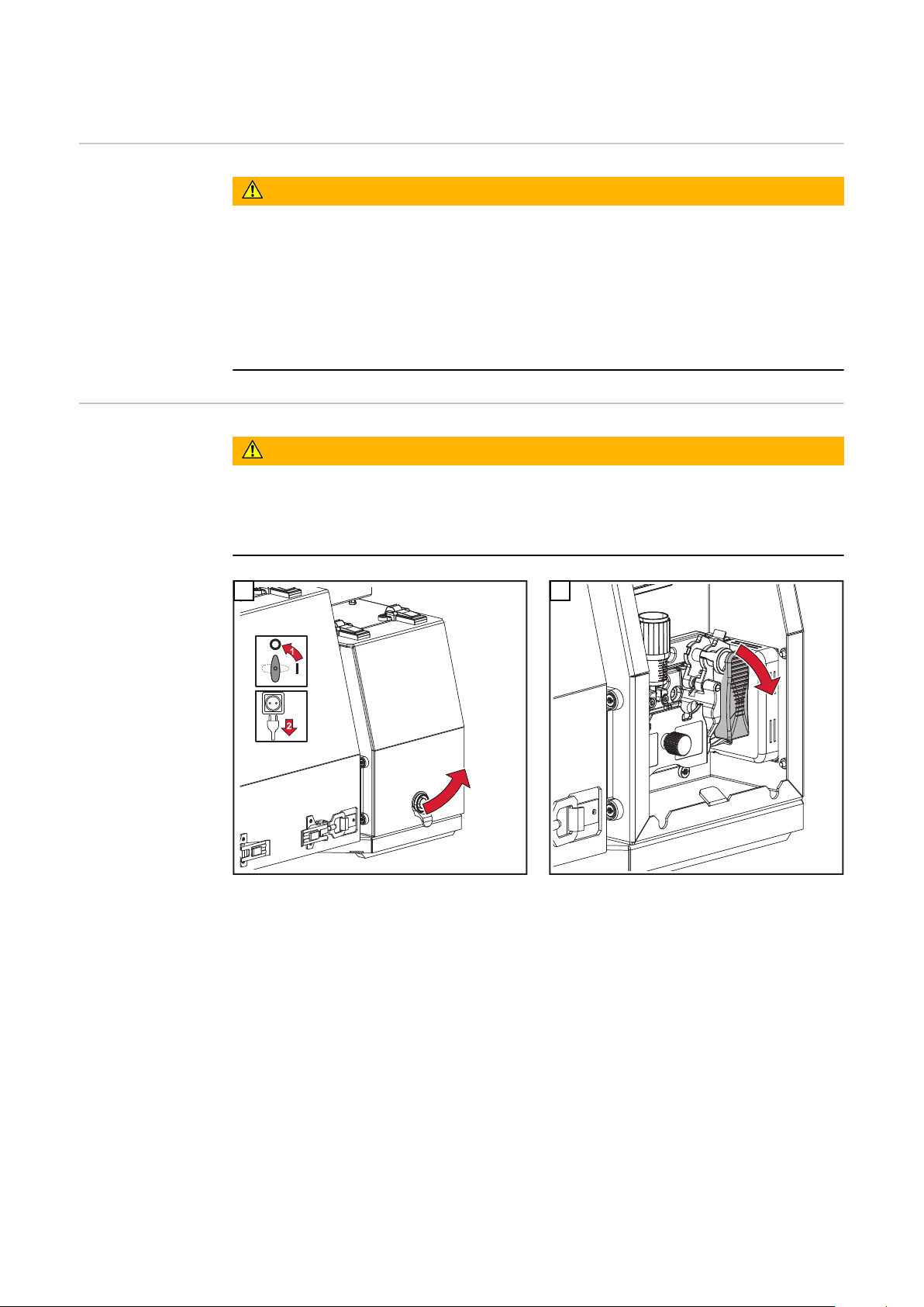
Before starting work, switch off all devices and components involved, and
▶
disconnect them from the grid.
Secure all devices and components involved so they cannot be switched back
▶
on.
After opening the device, use a suitable measuring instrument to check that
▶
electrically charged components (such as capacitors) have been discharged.
1
Use screws from the scope of supply of the spool holder
2
2 x M5 x 12 mm, tightening torque = 3 Nm / 2.21 lb-ft
42

1
3
1
2
2 x
2
1
1
Repeat work steps 2 and 3 on the other side of the wirefeeder
4
EN-US
Mounting the
D450 spool holder without cover
1
Use screws from the scope of supply of the spool holder
2
4 x M5 x 12 mm, tightening torque = 3 Nm / 2.21 lb-ft
43

1
3
2
3
4
5
6
1
3
1
2
2
2
2
4
4
4
4
Repeat work steps 2 and 3 on the other side of the wirefeeder
4
Mounting the
crane transport
option
Mounting the
hosepack holder
option
1
6 x M8 x 20 mm, tightening torque = 21 Nm /
15.49 lb-ft;
Crane transport option mounted on D300 spool
holder
1
Screws and mounting material from
the scope of supply of the crane transport option.
The option is mounted on the D450
spool holder without spool cover in the
same way.
8 x M5 x 12 mm, tightening torque = 3 Nm / 2.21 lb-ft
44
Mounting the
2
2
2
2
1
3
1
1
1
2
3
3
3
3
4 x M5x12 mm
1
2
1
2
2
2
1
2
2
2
2
tool tray option
1
2
EN-US
4 x brass spacer M5x12 mm, tightening torque =
2.1 Nm / 1.55 lb-ft
4 x M5 x 12 mm, tightening torque = 3 Nm / 2.21
lb-ft
Mounting the
boom mounting
kit option
1
4 x M8 x 25 mm + M8 washer + NL8
Tightening torque = 21 Nm / 15.49 lb-ft
2
4 x M8 x 30 mm + M8 washer + NL8
Tightening torque = 21 Nm / 15.49 lb-ft
45
Connecting the wirefeeder to the power source
3
1
3
2
Safety
Danger from electrical current.
This can result in serious personal injury and damage to property.
▶
▶
▶
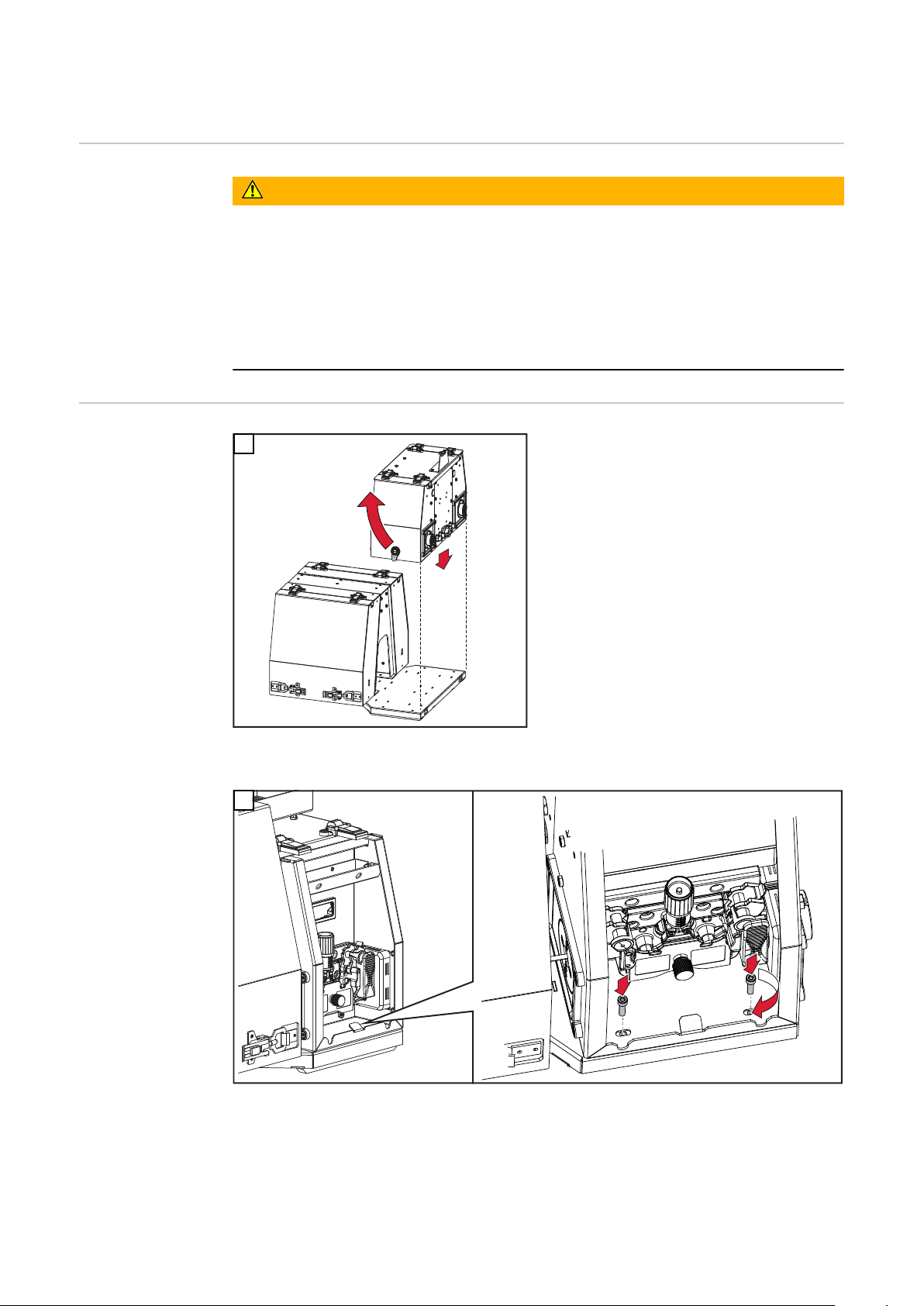
General The wirefeeder is connected to the power source by means of the interconnect-
ing hosepack.
Connecting the
wirefeeder to the
power source
WARNING!
Before starting work, switch off all devices and components involved, and
disconnect them from the grid.
Secure all devices and components involved so they cannot be switched back
on.
After opening the device, use a suitable measuring instrument to check that
electrically charged components (such as capacitors) have been discharged.
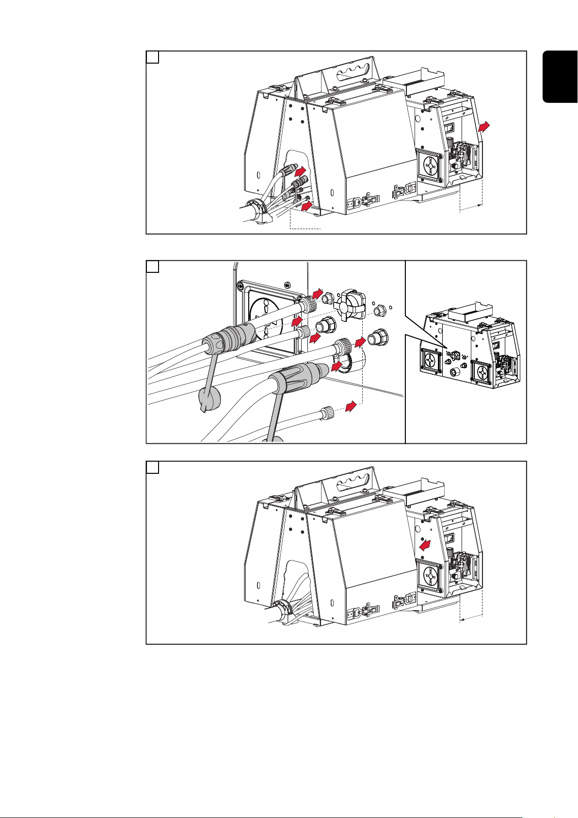
1
Connecting the wirefeeder to the
power source is described with reference to the WF 25i Dual with D300
spool holder.
The WF 25i Dual with D450 spool
holder is connected to the power
source in the same way.
46
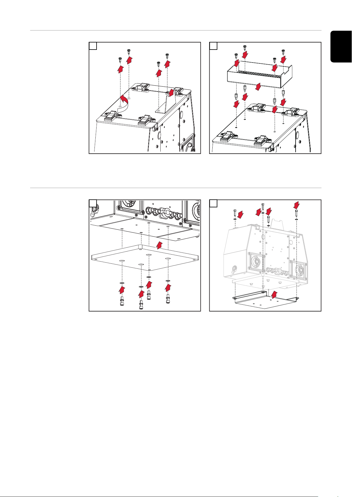
2
2 x M5 x 12 mm
Repeat work steps 1 and 2 on the other side of the wirefeeder
3
1
2
3
Gas 2
4
Gas 2
6
5
2
3
4
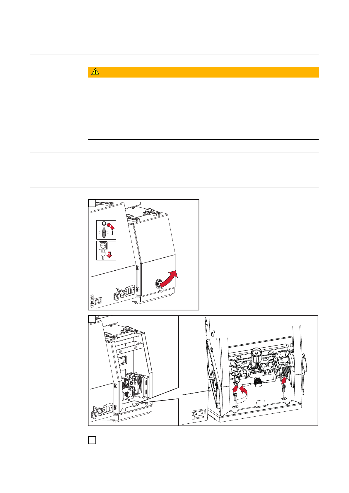
1
1
Push wirefeeder to the front;
Guide interconnecting hosepack and gas 2 through the spool holder
5
EN-US
Connect the interconnecting hosepack and gas 2 to the wirefeeder
6
Push the wirefeeder back into the original position
47

2
1
1
7
2
11
2 x M5 x 12 mm, tightening torque = 3 Nm / 2.21lb-ft
Repeat work step 7 on the other side of the wirefeeder
8
9
Connecting the
extension hosepack
Fix the strain-relief device of the interconnecting hosepack to the wirespool
10
holder with 2 M5 x 12 mm screws
Tightening torque = 3 Nm / 2.21 lb-ft
WARNING!
Danger from electric current due to defective system components and incorrect operation.
This can result in serious personal injury and damage to property.
All cables, leads, and hosepacks must always be securely connected, undam-
▶
aged, and correctly insulated.
Only use adequately dimensioned cables, leads, and hosepacks.
▶
48

1
* For water-cooled hosepack only
CON = interconnecting hosepack
EXT = extension hosepack
EN-US
2
49
Connecting the welding torch
3
1
Safety
Connecting a
MIG/MAG welding torch
WARNING!
Danger from electrical current.
This can result in serious personal injury and damage to property.
Before starting work, switch off all devices and components involved, and
▶
disconnect them from the grid.
Secure all devices and components involved so they cannot be switched back
▶
on.
After opening the device, use a suitable measuring instrument to check that
▶
electrically charged components (such as capacitors) have been discharged.
WARNING!
Danger from electrical current due to inadequate connections.
This can result in serious personal injury and damage to property.
All cables, leads, and hosepacks must be securely connected, undamaged,
▶
correctly insulated, and adequately sized.
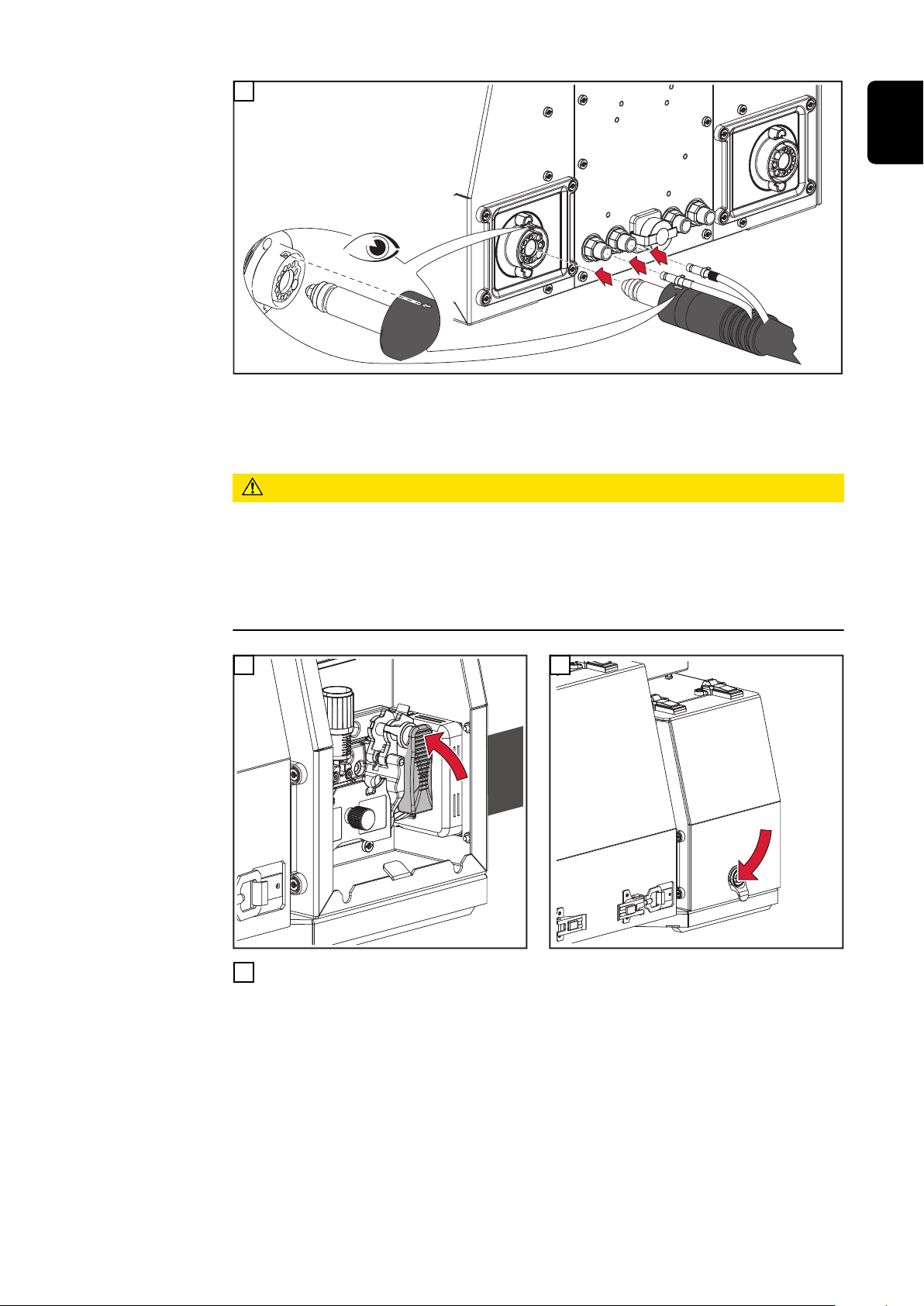
1
2
50
*
*
3
4
5
3
1
1
* only if the coolant connections are installed in the wirefeeder and for wa-
ter-cooled welding torches;
Observe the color coding of the coolant connections!
CAUTION!
Danger due to lack of coolant.
If the coolant hoses of one welding torch are terminated, the other welding torch
is also no longer supplied with coolant.
Overheating and damage to property may result
If coolant connections are present, always connect the coolant hoses of both
▶
welding torches.
EN-US
4
Repeat the work steps on the other side of the wirefeeder
6
5
51

Inserting/changing feed rollers
2
1
4
4
5
6
3
6
3
31
2
4
5
7
Safety
WARNING!
Danger from electrical current.
This can result in serious personal injury and damage to property.
Before starting work, switch off all devices and components involved, and
▶
disconnect them from the grid.
Secure all devices and components involved so they cannot be switched back
▶
on.
After opening the device, use a suitable measuring instrument to check that
▶
electrically charged components (such as capacitors) have been discharged.
General The feed rollers are not inserted in the system when first delivered.
In order to guarantee optimum feeding of the wire electrode, the feed rollers
must be adjusted to the wire diameter and the wire alloy to be welded.
NOTE!
Danger due to deficient feed rollers.
This can result in poor-quality weld properties.
Only use feed rollers which match the wire electrode.
▶
Inserting/changing feed rollers
An overview of the available feed rollers and their possible uses can be found in
the Spare Parts Lists.
CAUTION!
Danger due to feed roller holders shooting upwards.
This could result in injury.
When unlocking the clamping lever, keep fingers away from the area to the
▶
left and right of the clamping lever.
1
2
52

CAUTION!
3
8
6
7
9
3
1
2
2
5
4
4
4
5
5
6
1
2
3
Danger due to open feed rollers.
This could result in injury.
After inserting/changing the feed rollers, always install the protective cover
▶
of the 4-roller drive.
3
4
EN-US
53

Remounting the D450 brake for operation with a
(1)
(2)
1
D300 wirespool
Remounting the
D450 brake for
operation with a
D300 wirespool
If the D450 spool holder without spool cover is to be operated with a D300
wirespool, the brake must be remounted:
(1) Mounting position of the brake when using wirespools with a diameter of
450 mm
(2) Mounting position of the brake when using wirespools with a diameter of
300 mm
Remove M16 screw at the rear of the brake
1
2
WF 25i Dual with D450 spool holder
Re-fix the brake in the new position using the M16 screw
3
NOTE!
When using a D300 wirespool on the D450 spool holder, the braking force of the
D450 brake must also be adjusted.
54

Inserting the wirespool/basket-type spool
EN-US
Safety
WARNING!
Danger from electrical current.
This can result in serious personal injury and damage to property.
Before starting work, switch off all devices and components involved, and
▶
disconnect them from the grid.
Secure all devices and components involved so they cannot be switched back
▶
on.
After opening the device, use a suitable measuring instrument to check that
▶
electrically charged components (such as capacitors) have been discharged.
WARNING!
Danger from springiness of spooled wire electrode.
Serious personal injuries may result.
Wear safety goggles.
▶
When inserting the wirespool/basket-type spool, hold the end of the wire
▶
electrode firmly to avoid injuries caused by the wire electrode springing back.
WARNING!
Danger from falling wirespool/basket-type spool.
This can result in serious personal injury and damage to property.
Ensure that the wirespool/basket-type spool including basket-type spool ad-
▶
apter is always firmly seated on the wirespool holder.
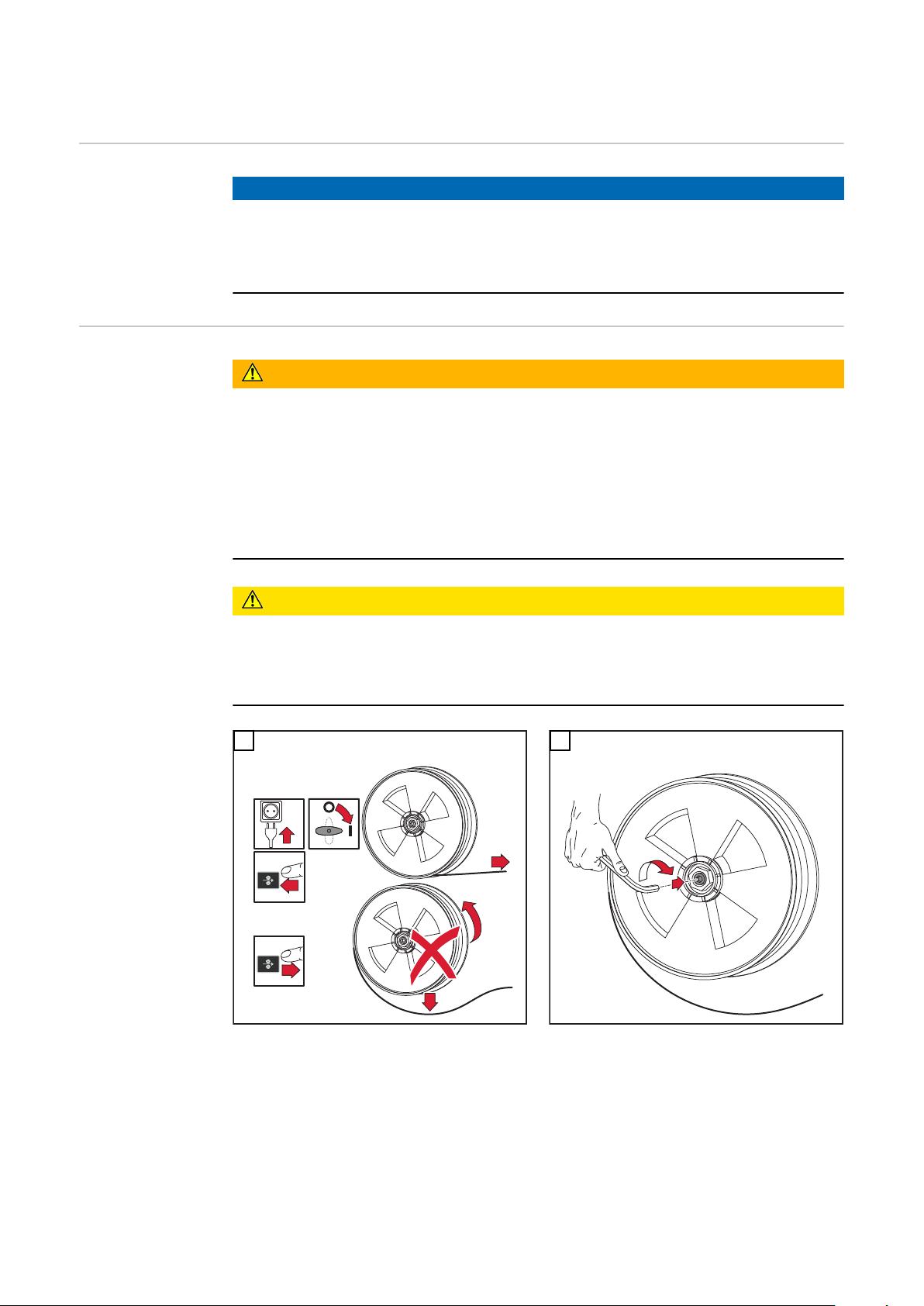
Inserting the
D300 wirespool
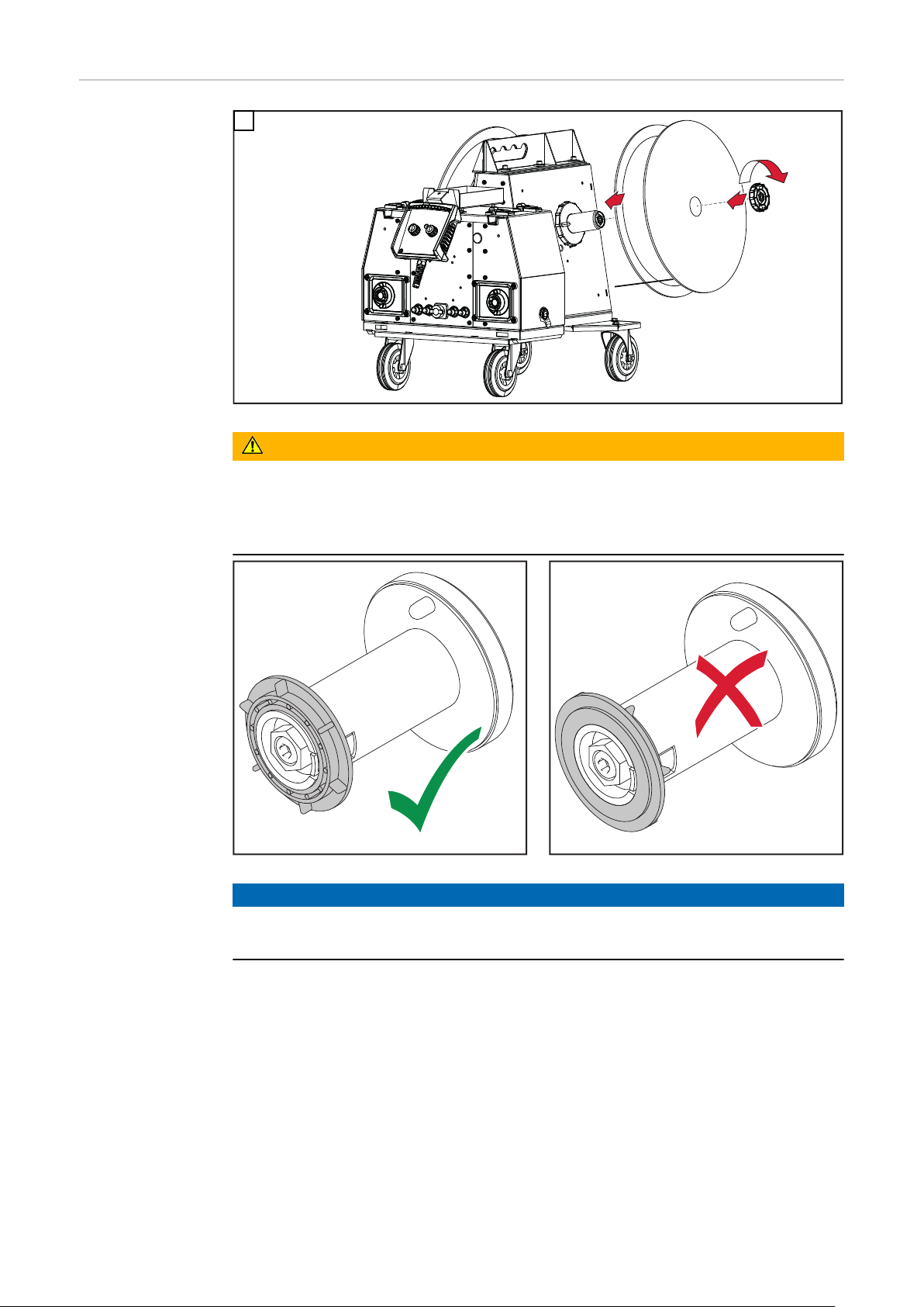
1
WARNING!
Danger due to falling wirespool as a result of the locking ring being fitted the
wrong way round.
This can result in severe personal injury and damage to property.
Always position the locking ring as shown below.
▶
55

Inserting the
3
4
D300 baskettype spool
WARNING!
Danger from falling basket-type spool due to missing basket-type spool adapter.
This can result in severe personal injury and damage to property.
When working with basket-type spools, only use the basket-type spool ad-
▶
apter supplied with the device.
WARNING!
Danger from falling basket-type spool.
This can result in severe personal injury and damage to property.
Place the basket-type spool on the adapter provided in such a way that the
▶
bars on the spool are inside the adapter guideways.
1 2
WARNING!
56
Danger due to falling basket-type spool as a result of the locking ring being fitted the wrong way round.
This can result in severe personal injury and damage to property.
Always position the locking ring as shown below.
▶

EN-US
57
Inserting the
1
3
2
D450 wirespool
1
WARNING!
Danger due to falling wirespool as a result of the locking ring being fitted the
wrong way round.
This can result in severe personal injury and damage to property.
Always position the locking ring as shown below.
▶
58
NOTE!
Use appropriate spool adapters for applications with 60 lb flux core wire spools.
Spool adapters for 60 lb flux core wire spools are not available from Fronius.

Threading the Wire Electrode
EN-US
General
Preparation
NOTE!
The wire electrode can be threaded using any wire-threading button of another
system component – for example, the wire-threading button of the power
source.
The function of the wire-threading button is the same for all system components
of the manufacturer.
More information on the function of the wire-threading button can be found
▶
from page 38.
WARNING!
Danger from springiness of spooled wire electrode.
Serious personal injuries may result.
Wear safety goggles.
▶
When inserting the wirespool/basket-type spool, hold the end of the wire
▶
electrode firmly to avoid injuries caused by the wire electrode springing back.
CAUTION!
Danger due to unintentional ignition of an arc.
Personal injury and damage to property may result.
Before starting work, disconnect the ground earth connection between the
▶
welding system and workpiece.
CAUTION!
Danger due to sharp end of the wire electrode.
Personal injury and damage to property may result.
Thoroughly deburr the end of the wire electrode before inserting.
▶
1
59
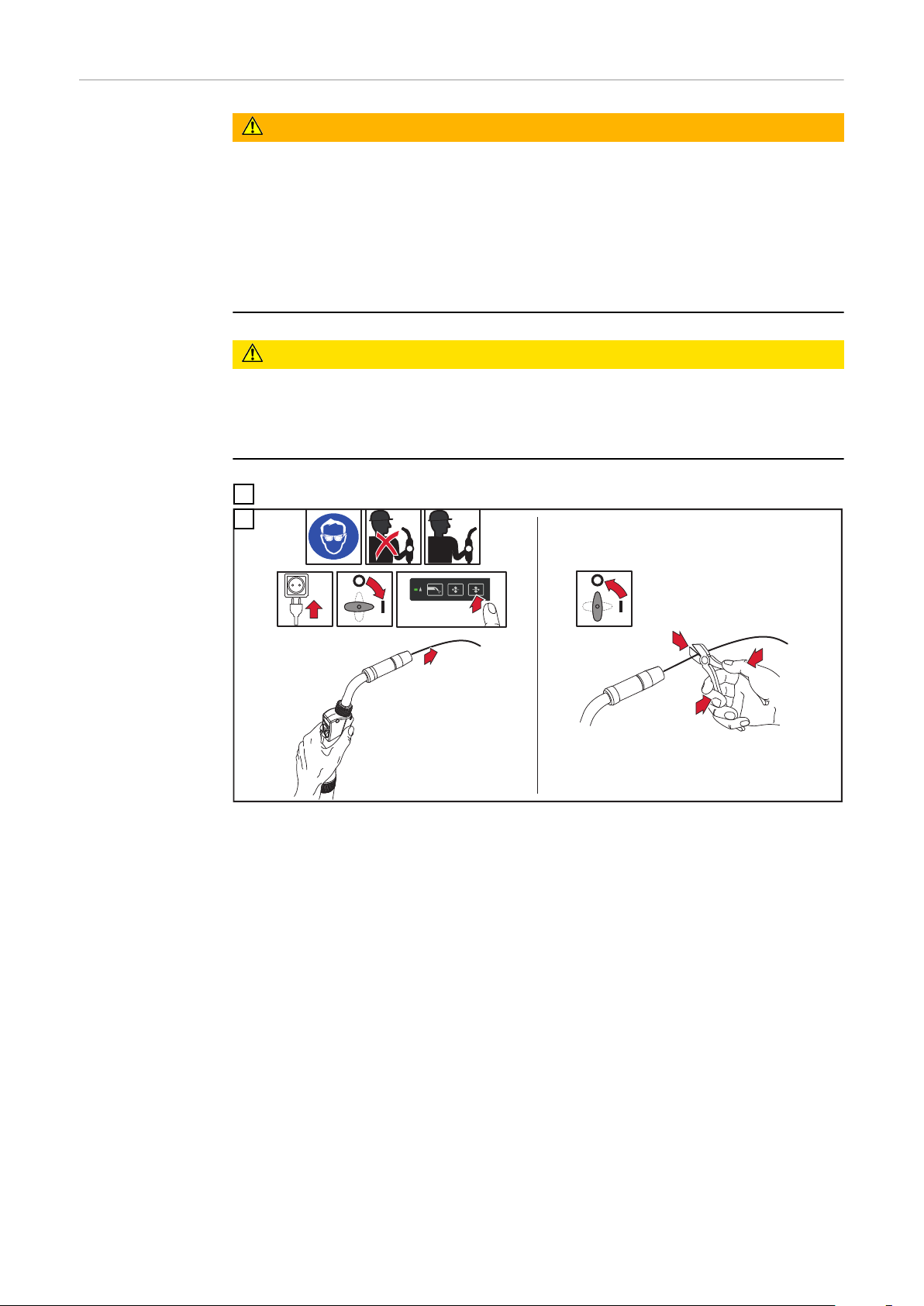
Threading the
4
5
3
2
1
6
wire electrode
WARNING!
Danger due to emerging wire electrode.
Serious personal injuries may result.
Hold the welding torch so that the tip of the welding torch points away from
▶
the face and body.
Wear suitable protective goggles.
▶
Do not point the welding torch at people.
▶
Ensure that the wire electrode does not touch any electrically conductive ob-
▶
jects.
CAUTION!
Danger due to unintentional ignition of an arc.
Personal injury and damage to property may result.
Before starting work, disconnect the ground earth connection between the
▶
welding system and workpiece.
Lay the torch hosepack straight
1
2
60
Setting the con-
1
tact pressure
CAUTION!
Danger from excessive contact pressure.
This can result in damage to property and poor weld properties.
Set the contact pressure in such a way that the wire electrode is not de-
▶
formed but nevertheless ensures proper wirefeeding.
EN-US
1
Contact pressure standard values for
U-groove rollers:
Steel: 4 - 5
-
CrNi: 4 - 5
-
Aluminum: 0.5 - 1.5
-
Tubular covered electrodes: 2 - 3
-
Contact pressure standard values for
knurled rollers:
Tubular covered electrodes: 1 - 2
-
Observe the sticker on the wire drive!
61
Adjusting the brake
1
4
5
STOP
6
7
3
1
2
2
1
General
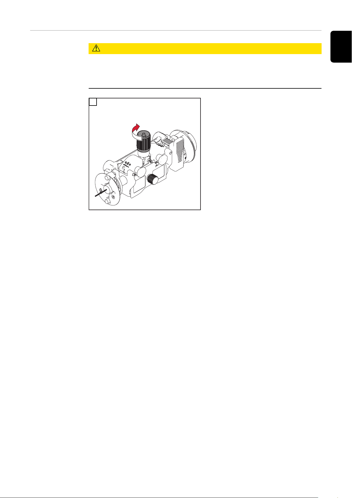
Adjusting the
D300 brake
NOTE!
Overrunning of the brake can result in damage to property.
After releasing the torch trigger/wire-threading button, the wirespool must
▶
stop unreeling.
If it continues unreeling, readjust the brake.
▶
WARNING!
Danger due to emerging wire electrode.
Serious personal injuries may result.
Hold the welding torch so that the tip of the welding torch points away from
▶
the face and body.
Wear suitable protective goggles.
▶
Do not point the welding torch at people.
▶
Ensure that the wire electrode does not touch any electrically conductive ob-
▶
jects.
CAUTION!
Danger due to unintentional ignition of an arc.
Personal injury and damage to property may result.
Before starting work, disconnect the ground earth connection between the
▶
welding system and workpiece.
1
2
62
2
4
STOP
OK
3
1
3
EN-US
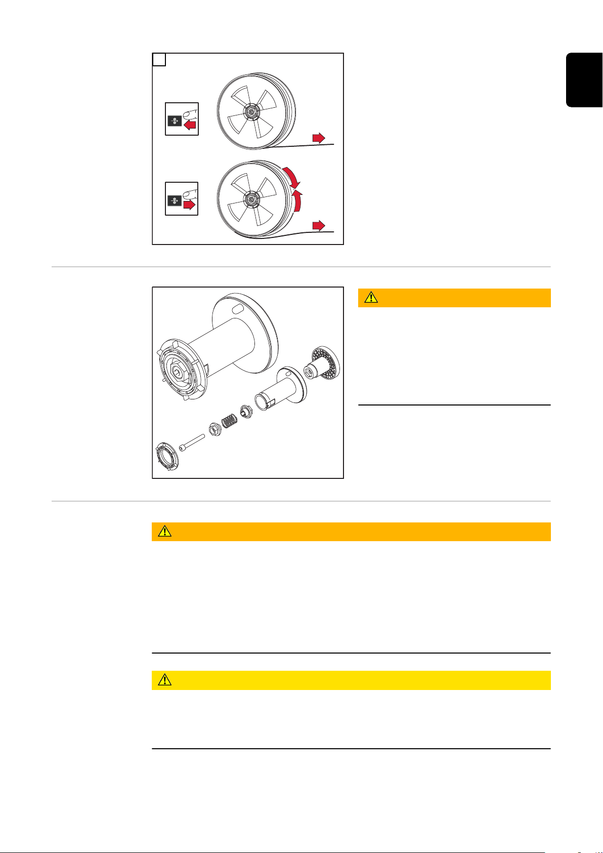
Design of the
D300 brake
Adjusting the
brake on the WF
25i Dual D450
WARNING!
Danger from incorrect installation.
This can result in severe personal injury and damage to property.
Do not dismantle the brake.
▶
Maintenance and servicing of
▶
brakes is to be carried out by
trained, qualified personnel only.
The brake is only available as a complete unit.
The illustration of the brake is for information purposes only.
WARNING!
Danger due to emerging wire electrode.
Serious personal injuries may result.
Hold the welding torch so that the tip of the welding torch points away from
▶
the face and body.
Wear suitable protective goggles.
▶
Do not point the welding torch at people.
▶
Ensure that the wire electrode does not touch any electrically conductive ob-
▶
jects.
CAUTION!
Danger due to unintentional ignition of an arc.
Personal injury and damage to property may result.
Before starting work, disconnect the ground earth connection between the
▶
welding system and workpiece.
63

1
4
5
STOP
6
7
3
1
2
1
2
1
2
4
STOP
OK
3
1
3
2
64

Design of the
D450 brake
The brake is only available as a complete unit.
The illustration of the brake is for information purposes only.
Preliminary design of the D450 brake
WARNING!
Danger from incorrect installation.
This can result in severe personal injury and damage to property.
Do not dismantle the brake.
▶
Maintenance and servicing of brakes is to be carried out by trained, qualified
▶
personnel only.
EN-US
65

Commissioning
Safety
Warning of electrically live (hot),
exposed parts on
WF 25i Dual with
spool holder
D450 without
spool cover
WARNING!
Danger from incorrect operation and work that is not carried out properly.
This can result in serious personal injury and damage to property.
All the work and functions described in this document must only be carried
▶
out by technically trained and qualified personnel.
Read and understand this document in full.
▶
Read and understand all safety rules and user documentation for this equip-
▶
ment and all system components.
Only for WF 25i Dual with spool holder D450 without spool cover:
When the dual head wirefeeder is connected to the power source and the
power source is on, certain electrical
live (hot) parts are exposed!
WARNING!
Electric shock can kill!
Danger of electric shock due to electrically live (hot), exposed parts.
Touching electrically live (hot) parts can cause serious personal injury.
Do not touch the following electrically live (hot) parts:
▶
Wirespool,
Wire electrode,
Current sockets,
Welding torch connection,
Feed rollers (with feed roller cover open).
Wear dry, insulating gloves.
▶
Do not wear wet or damaged gloves.
▶
Use a dry underlayer to insulate the floor and work area.
▶
66

Requirements
for commissioning
Commissioning The wirefeeder is started up in manual applications by pressing the torch trigger
The following requirements must be fulfilled for commissioning of the wirefeeder:
Wirefeeder connected to power source by means of interconnecting hosep-
-
ack
Welding torch connected to wirefeeder
-
Feed rollers inserted into wirefeeder
-
Wirespools/basket-type spools and their adapters inserted into wirefeeder
-
Wire electrodes threaded in
-
Contact pressure of the feed rollers set
-
Brakes adjusted
-
All covers closed, all side parts mounted, and all protection devices in good
-
order and installed in the location intended
Welding process line selected
-
and in automated applications by an active signal to start welding.
EN-US
Note for TIG AC
applications
NOTE!
If the dual-head wirefeeder is integrated into a multiprocess welding system,
the wirefeeder must be disconnected from the power source before activating a
TIG AC welding process!
Terminate the interconnecting hosepack!
▶
67

Selecting the welding process line
1
2
Selecting the
welding
process line
Selecting the
welding process
line using the
torch trigger
Selecting the
welding process
line using the
button/LED on
the wirefeeder
The welding process line can be selected in the following ways:
Using the torch trigger on the welding torch
-
Using the button/LED on the wirefeeder
-
Using the gas-test, wire-return, and wire-threading buttons on the wirefeeder
-
On the power source
-
Using the RC Panel Standard or RC Panel Pro remote control
-
NOTE!
It is not possible to switch to the other welding process line during the welding
process.
Press the corresponding torch trigger to switch to the other welding process line.
Press the corresponding button on the wirefeeder to switch to the other welding
process line.
If the LED on the button lights up, this welding process line is activated.
1
Button/LED on the wirefeeder
1, 2 = welding process lines
68

Selecting the
welding process
line using the
gas-test, wirereturn, and wirethreading buttons
If one of the gas-test, wire-return, or wire-threading buttons is pressed on one
side of the wirefeeder, this welding process line is activated.
The LED of the corresponding button on the wirefeeder lights up.
1
EN-US
Selecting the
welding process
line on the power
source or using
RC Panel Pro remote control
Selecting the
welding process
line using the RC
Panel Standard
remote control
The power source or the RC Panel Pro remote control detects when a dual-head
wirefeeder is in the welding system. The status line of the power source display
shows the active welding process line.
To change the welding process line, touch the welding process line displayed in
the status line and confirm the subsequent confirmation prompt to change the
welding process line.
For details on selecting the welding process line, refer to the power source Operating Instructions.
To change the welding process line, press the corresponding selection dial on the
remote control twice:
Left-hand selection dial = welding process line 1
-
Right-hand selection dial = welding process line 2
-
The display of the remote control shows the change of the welding process line.
After the display goes out, the LED on the corresponding selection dial lights up
to indicate the active welding process line.
69

Troubleshooting
Safety
WARNING!
Danger from incorrect operation and work that is not carried out properly.
This can result in serious personal injury and damage to property.
All the work and functions described in this document must only be carried
▶
out by technically trained and qualified personnel.
Read and understand this document in full.
▶
Read and understand all safety rules and user documentation for this equip-
▶
ment and all system components.
WARNING!
Danger from electrical current.
This can result in serious personal injury and damage to property.
Before starting work, switch off all devices and components involved, and
▶
disconnect them from the grid.
Secure all devices and components involved so they cannot be switched back
▶
on.
After opening the device, use a suitable measuring instrument to check that
▶
electrically charged components (such as capacitors) have been discharged.
WARNING!
Danger due to hot system components and/or equipment.
This can result in serious burns or scalding.
Before starting work, allow all hot system components and/or equipment to
▶
cool to +25°C/+77°F (e.g., coolant, water-cooled system components,
wirefeeder drive motor, etc.).
Wear suitable protective equipment (e.g., heat-resistant gloves, safety
▶
goggles, etc.) if cooling down is not possible.
Troubleshooting Make a note of the serial number and configuration of the device, and provide
the service team with a detailed error description if:
Errors occur that are not covered in this document
-
The troubleshooting measures provided in this document are unsuccessful
-
70

Power source not working
Power source switched on; displays and indicators do not illuminate
Cause:
Remedy:
Cause:
Remedy:
Cause:
Remedy:
Cause:
Remedy:
Nothing happens after pressing torch trigger
Power source power switch is ON and indicators are lit up
Cause:
Remedy:
No welding current
Power source switched on, displays illuminate
Mains lead damaged or broken, mains plug not inserted
Check mains lead, if necessary insert mains plug
Mains socket or mains plug faulty
Replace faulty parts
Mains fuse protection
Replace mains fuse
Short circuit on the 24 V power supply of the SpeedNet connection
or external sensor
Disconnect connected components
Welding torch or welding torch control line faulty
Replace the welding torch
EN-US
Cause:
Remedy:
Cause:
Remedy:
no shielding gas
all other functions present
Cause:
Remedy:
Cause:
Remedy:
Cause:
Remedy:
Cause:
Remedy:
Cause:
Remedy:
Incorrect ground connection
Check ground connection for polarity
Power cable in welding torch damaged or broken.
Replace welding torch
Gas cylinder empty
Change gas cylinder
Gas pressure regulator faulty
Replace gas pressure reducer
Gas hose not attached, or damaged
Attach or replace gas hose
Welding torch faulty
Change welding torch
Gas solenoid valve faulty
Inform the service team
71

Irregular wire speed
Cause:
Remedy:
Braking force has been set too high
Loosen the brake
Cause:
Remedy:
Cause:
Remedy:
Cause:
Remedy:
Cause:
Remedy:
Wirefeed issues
For applications with long hosepacks
Cause:
Remedy:
Welding torch gets very hot
Cause:
Remedy:
Contact tip hole too narrow
Use suitable contact tip
Inner liner in the welding torch faulty
Check the inner liner for kinks, dirt, etc. and replace if necessary
Feed rollers not suitable for wire electrode used
Use suitable feed rollers
Feed rollers have the wrong contact pressure
Optimize contact pressure
Improper laying of the hosepack
Lay hosepack as straight as possible while avoiding tight bending radii
Welding torch is inadequately sized
Observe duty cycle and load limits
Cause:
Remedy:
For water-cooled systems only: Coolant flow too low
Check coolant level, coolant flow rate, coolant contamination, etc.
For more detailed information, refer to the Operating Instructions for
the cooling unit
72

Poor-quality weld properties
Cause:
Remedy:
Incorrect welding parameters
Check settings
EN-US
Cause:
Remedy:
Cause:
Remedy:
Cause:
Remedy:
Cause:
Remedy:
Cause:
Remedy:
Cause:
Remedy:
Cause:
Remedy:
Poor ground earth connection
Establish good contact with workpiece
Too little or no shielding gas
Check pressure regulator, gas hose, gas solenoid valve, welding torch
gas connection, etc.
Welding torch leaks
Change welding torch
Incorrect or heavily worn contact tip
Change contact tip
Incorrect wire alloy or incorrect wire diameter
Check wire electrode in use
Incorrect wire alloy or incorrect wire diameter
Check the weldability of the parent material
Shielding gas not suitable for wire alloy
Use correct shielding gas
Cause:
Remedy:
Wear of the wirefeeding roller groove
Replace wirefeeding rollers
73

Service, maintenance and disposal
General The device only requires minimal of service and maintenance under normal oper-
ating conditions. However, several points must be observed for the welding system to remain operational for years to come.
Safety
WARNING!
Danger from incorrect operation and work that is not carried out properly.
This can result in serious personal injury and damage to property.
All the work and functions described in this document must only be carried
▶
out by technically trained and qualified personnel.
Read and understand this document in full.
▶
Read and understand all safety rules and user documentation for this equip-
▶
ment and all system components.
WARNING!
Danger from electrical current.
This can result in serious personal injury and damage to property.
Before starting work, switch off all devices and components involved, and
▶
disconnect them from the grid.
Secure all devices and components involved so they cannot be switched back
▶
on.
After opening the device, use a suitable measuring instrument to check that
▶
electrically charged components (such as capacitors) have been discharged.
WARNING!
At every startup
Every 6 months
Danger due to hot system components and/or equipment.
This can result in serious burns or scalding.
Before starting work, allow all hot system components and/or equipment to
▶
cool to +25°C/+77°F (e.g., coolant, water-cooled system components,
wirefeeder drive motor, etc.).
Wear suitable protective equipment (e.g., heat-resistant gloves, safety
▶
goggles, etc.) if cooling down is not possible.
Check all hosepacks and the ground earth connection for damage. Replace
-
any damaged components.
Check feed rollers and inner liners for damage. Replace any damaged com-
-
ponents.
Check contact pressure of the feed rollers and adjust if necessary.
-
CAUTION!
Danger from compressed air at close range.
Electronic parts may be damaged.
Do not bring the air nozzle too close to electronic parts.
▶
74

Open covers, dismantle device side panels, and blow the inside of the device
-
clean with dry, reduced compressed air. After cleaning, restore the system to
its original condition.
Disposal Materials should be disposed of according to valid local and national regulations.
EN-US
75

Technical data
WF 25i Dual
Supply voltage 24 V DC / 60 V DC
Nominal current 0.5 A / 1.2 A
Welding current
at 10 min/40 °C (104 °F)
Maximum pressure of shielding gas 7 bar
Coolant Original Fronius
Maximum pressure of coolant 5 bar
Wire speed 1 - 25 m/min
Wire drive 4-roller drive
Wire diameter 0.8 - 1.6 mm
Wirespool diameter Max. 300 mm
Wirespool weight Max. 19 kg
40% ED* / 500 A
60% ED* / 450 A
100% ED* / 360 A
101.53 psi
72.53 psi
39.37 - 984.25 ipm
0.03 - 0.06 in.
Max. 11.81 in.
Max. 41.89 Ib.
Protection class IP 23
Mark of conformity S, CE, CSA
Dimensions I x w x h
(without options)
Weight
(without options)
* ED = Duty cycle
550 x 256 x 354.5 mm
21.65 x 10.08 x 13.96 in.
18.8 kg
41.45 Ib.
76

D300 spool holder with cover
Wirespool diameter Max. 300 mm
Max. 11.81 in.
Wirespool weight Max. 19 kg
Max. 41.89 Ib.
Protection class IP 23
Dimensions l × w × h 620 x 557 x 444 mm
24.37 x 21.93 x 17.48 in.
Weight - kg
- Ib.
EN-US
D450 spool holder without cover
HP 70i
Wirespool diameter Max. 450 mm
Max. 17.72 in.
Wirespool weight Max. 27.2 kg
Max. 60 Ib.
Protection class IP 20
Dimensions l × w × h 616 x 506 x 424 mm
24.25 x 19.92 x 16.69 in.
Weight - kg
- Ib.
Welding current at 10 min/40°C
(104°F)
* ED = Duty cycle
40% ED* / 400 A
60% ED* / 365 A
100% ED* / 320 A
HP 95i
Welding current at 10 min/40°C
(104°F)
* ED = Duty cycle
40% ED* / 500 A
60% ED* / 450 A
100% ED* / 360 A
77

78

EN-US
79

 Loading...