

Page 1
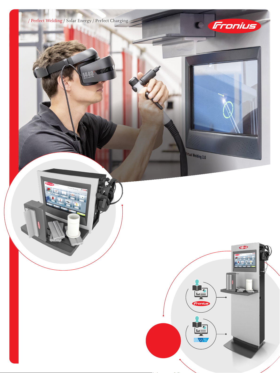
WELDUCATION
THEORY KIT
READY-TO-WELD PACKAGE
Virtual Welding offers the user a complete package per process and
a comprehensive didactic concept for efficient welder training.
/ Virtual Training
with pre-defined welding tasks, based on
IIW welder training
/ Predefined theory documents
for theoretical welding knowledge
/ Knowledge check
to review the learned
content
THEORIE & PRACTICE COMBINED!
Integration of theory documents and knowledge
check using multiple-choice questions.
/ Three packages available:
MMA, TIG, MIG/MAG
/ Flexibility in content:
/ Fronius documents & questions
/ DVS documents & questions
/ PDF upload function for customer documents
/ All including
pre-dened
welding tasks for
headache free
starting.
Page 2
STRESS-FREE STARTING
Fronius Middle East FZE
P.O. Box: 263241
Jebel Ali / JAFZA ONE BUILDING
Dubai / U.A.E
Telephone +971 (0) 56 499 8224
contact.middleeast@fronius.com
www.fronius.ae/pw
Fronius (Thailand) Ltd.
Pinthong Industrial Estate I
789/193 Moo 1, Sriracha,
Chonburi 20230
Building: P17/B1
Thailand
Telephone +66 (033) 047421
sales.Thailand@fronius.com
www.fronius.co.th
Fronius India Private Limited
Plot no BG-71/2/B,
Pimpri Industrial Area,
MIDC- Bhosari,
Pune- 411026
India
Telephone + 91 98 20 60 52 07
sales.india@fronius.com
www.fronius.in
Designation Fronius International
Schweißanweisung Nr.: Grundwerkstoff - Gruppen ISO 15608
Fronius SWPS Nr.: Werkstückdicke [mm]:
Nahtdicke [mm]
Prüfer oder Prüfstelle: Geltungsbereich Außendurchmesser [mm]:
Verbindungsnaht, Nahtart: Kehlnaht Geltungsbereich Werkstoffdicke [mm]:
Fugenvorbereitung: nein Geltungsbereich Nahtdicke [mm]:
Oberflächen Vorbereitung
frei von Zunder und Rost
Schweißposition:
Joint Design / Gestaltung der Verbindung
Welding sequences / Schweißfolgen
Welding details / Einzelheiten für das Schweißen
* of electrical arc energy or electrical arc performance ISO/TR 18491
* aus elektrischer Lichtbogenenergie oder elektrischer Lichtbogenleistung ISO/TR 18491
** S = stringer; W = weave bead; tW = mm weave bead width; l = °leading; t = °tracking; n = neutral
** S = Strichraupe; W = Pendelraupe, tW = mm Pendelbreite; l = °stechend; t = °schleppend; n = neutral
Filler material: ISO 14341-A; AWS A5.1 designation; trade mark:
Schweißzusatzbezeichnung: EN ISO 2560-A; Handhabung:
Einzelheiten Schweißprozess, z.B. Name, Maschineneinstellung:
Gasdurchflussmenge [l/min]: Schweißstart-Temperatur [°C]:
Gasdüsendurchmesser [mm]: Zwischenlagentemperatur [°C]:
Einzelheiten Wurzelschutz: Haltetemperatur [°C]:
Einzelheiten Badsicherung: Wärmebehandlung/Aushärten:
Zeit, Temperatur, Verfahren:
Kontaktrohrabstand [mm]: Erwärmungs- und Abkühlrate:
Wolframelektrode/ø-Elektrode:
Additions and comments: e.g. standard notes, details of gauging, additional filler material /
Date / Datum : Signature and stamp / Unterschrift und Stempel :
10-15
─
2019 Mai
12-17
──10-15
─
─
─
─
Kreindl
─
─
FRONIUS Welding Procedure Specification /
(WPS)
Arc energy*
Streckenenergie
1,2
DC+
7,3-9,2
**S I 10°
─
PB (2F)
FM1 ≤ S360
10 mm
no
M21
Impulslichtbogen
4
─
─
G42 4 M21 3Si1; ER70-S6
Pulse arc
320. 9606-1 135 P FW FM1 S t10 PB ml-L2 B2 1,2mm
9-10
M1
320
─
─
─
fillet weld
free of scale and rust
ø filler
current /
Polung
according to / nach EN ISO 15612, EN ISO 15609-1
6.5 Pulsed Arc
With the pulsed arc, the material transfer is precisely controlled by pulses
(Figure 17).
In the base current phase, the energy input is reduced to such an extent that the
arc barely burns steadily and the surface of the workpiece is preheated. In the
pulsing current phase, an accurately timed current pulse guarantees a precise
detachment of the weld droplet.
Fig. 17: The pulsed arc.
The pulsed arc almost completely eliminates unwanted short-circuits and simul-
taneous droplet explosions. As a result there is virtually no uncontrolled spatter
with the pulsed arc.
6.6 Combined Arcs
Combined arcs are often made up of pulsed arcs and dip transfer arcs
(Figure 18).
Fig. 18: Combined arcs.
The penetration and heat input needed are generated in the pulsed arc phase.
The dip transfer arc phase takes care of the cooling in the weld pool, thus
ensuring better controllability of the weld pool.
25“Tungsten Inert Gas Welding” Training Documentation
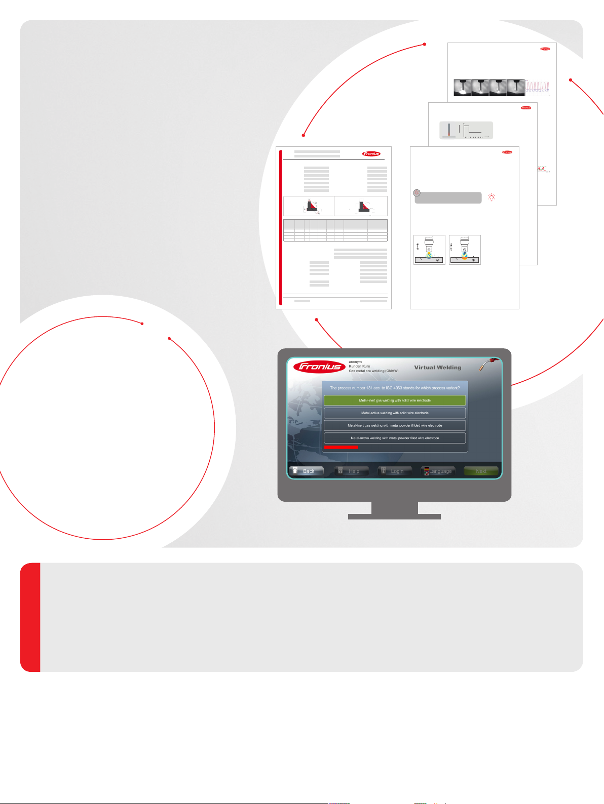
WITH THEORY KITS
Functionality of the pulsed arc
The theory kits make it possible to use Virtual
Welding and thus the most modern teaching
methods quickly and adapted to your training.
THE KITS CONTAIN:
/ Theory documents (Fronius OR DVS) per process
/ Curriculum, based on the IAB 089 (IIW guideline on
requirements for welding education and examination)
/ Over 70 welding exercises, with matching WPS
/ More than 170 theory questions, structured
per chapter in the curriculum
/ All can be modified and adapted to meet your
education needs
BENEFITS:
Bezeichnung
Modul 4600 Wels, Austria
Welding procedure No.: Parent material - ISO15608:
FRONIUS PWPS No.: Material thickness [mm]:
WPQR Nr.: Effective throat thickness [mm]:
Examiner or test center: Scope external diameter [mm]:
Type of weld: Scope material thickness [mm]:
Edge preparation: Scope throat thickness [mm]:
Surface preparation: Welding position:
Welding
Current
metal
process
Run
Strom
Zusatz
Schweißraupe
Schweißprozess
[A]
[mm]
ISO 4063
3 135 240-260 26-28 38-41
Details welding process, e.g. name, machine setting:
Details designation gas, e.g. ISO14175, manufacturer, trade mark:
Einzelheiten Schutzgas, z.B. ISO 14175, Hersteller, Markenname:
Gas flow rate [l/min]: Preheat temperature [°C]:
Gas nozzle diameter [mm]: Interpass temperature [°C]:
Details of root protection: Holding temperature [°C]:
Details of backing: Heat treatment/ageing:
Contact tube distance [mm]: Heating and cooling rates:
Tungsten electrode/diameter:
Froniusplatz 1
Standardschweißanweisung
Type of
Wire feed
Voltage
Speed of travel
Spannung
Schweißgeschwindigkeit
Drahtvorschub
polarity
[V]
[cm/min]
[m/min]
Stromart /
Time, temperature, method:
Ergänzungen und Anmerkungen:
[kJ/cm]
Torch position / angle **
Brenner-Führung / Anstellung
7.2.5 HOT-Start
Um die Elektrode leichter zünden zu können, wird beim HOT-Start am Schweiß-
gerät bei der Zündung für den Bruchteil einer Sekunde der Strom erhöht.
7.2.6 SOFT-Start
Die SOFT-Start-Methode wird speziell bei basischen Elektroden während des
Zündvorgangs genutzt, um die Porenbildung zu reduzieren.
5.10.2 TIG Welding with Alternating Current
TIG welding with alternating current is used with aluminum and magnesium.
Beim SOFT-Start wird durch die anfangs geringere Energie der Grundwerkstoff
This is because it is characteristic of aluminum, for example, that due to the
nicht tief aufgeschmolzen. Damit wird es möglich, den Ansatz zu überschwei-
metal’s high a nity for oxygen, an oxide layer immediately forms on all surfac-
ßen und das Schweißbad besser ausgasen zu lassen. Dies verhindert die An-
es that are exposed to the air.
satzporenbildung.
The oxide layer (Al
) has a melting point of approximately 2,050 °C, while
2O3
aluminum itself has a melting point of approximately 650 °C, depending on the
alloy. Where there is an oxide layer on the material, it is not possible to create
a welded joint as the metal would ow away in droplet form. The alternating
current destroys or displaces the oxide layer, thereby making welding possible.
TIG welding with alternating current is also known as TIG AC
welding.
The “cleaning half cycle” (electrode on the positive pole) alternates with a “cooling half cycle” (electrode on the negative pole). As a result of this alternation
7.3 Verständnisfragen
the oxide lm is destroyed and the electrode is simultaneously charged with a
su ciently high current.
Welche Schweißstromquellen werden für das Lichtbogenhandschweißen
There are exceptional cases in which light metals are TIG welded with direct
current. In such cases, the tungsten electrode is connected to the negative pole
and helium is used as the shielding gas.
Nach welchem Prinzip wird beim Lichtbogenhandschweißen die Lichtbo-
Ion
Ion
Welche Zusatzfunktion besitzen moderne Schweißstromquellen, um das
Polarity
Polarität
Electron
Elektron
Material
Material
Melting point
Schmelzpunkt
at approx. 660 °C
bei ca. 660 °C
Fig. 14: In the “cleaning half cycle”, the
electrode is connected to the positive
pole.
Advantages of the pulsed arc:
+ Low-spatter welding across the whole power range
Is (A)
200
150 %
+ Control of penetration during overlay welding
150
50 %
+ Processing of thicker wire electrode diameters for thin sheet metal weld-
HOT-Start
100
0 %
ing (e.g.: aluminum materials)
0
Abb. 26: Zündphase mit HOT-Start. Eingestellter Schweißstrom Is: 100 A.
Schweißspannung U (V)
Abb. 27: SOFT-Start-Zündung.
verwendet?
genlänge geregelt?
Ion
Ion
Polarity
Polarität
Electron
Zünden mit basisch umhüllten Stabelektroden zu erleichtern?
Elektron
Oxide layer
Material
Material
Melting point
Schmelzpunkt
at approx. 660 °C
bei ca. 660 °C
Fig. 15: In the “cooling half cycle”, the electrode is connected to the negative pole.
Oxide layer
Oxid-Schicht
Melting point
Schmelzpunkt
at approx. 2015 °C
bei ca. 2015 °C
Oxid-Schicht
Melting point
Schmelzpunkt
at approx. 2015 °C
bei ca. 2015 °C
HOT-Start
Zeit (Sekunden)
1,0
SOFT-Start
TIG AC welding
Training documentation "MIG/MAG welding" 28
Zeit (Sekunden)
Cleaning half cycle and
cooling half cycle
35Trainingsunterlage „Lichtbogenhandschweißen“
The integration of Virtual Welding in
the education can be started right away
Hassle-free, thanks to pre-defined curricula
Modularity in all parts; exercises can be
added or modified.
Faster setup – Virtual Welding can be
implemented in your education within the
blink of an eye!
/ Perfect Welding / Solar Energy / Perfect Charging
What began in 1945 as a one-man operation now sets technological standards in the fields of welding technology, photovoltaics and battery charging. Today, the
company has around 5,440 employees worldwide and 1,264 patents for product development show the innovative spirit within the company. Sustainable
development means for us to implement environmentally relevant and social aspects equally with economic factors. Our goal has remained constant throughout:
to be the innovation leader.
Further information about all Fronius products and our global sales partners and representatives can be found at www.fronius.com
THREE BUSINESS UNITS, ONE GOAL: TO SET THE STANDARD THROUGH TECHNOLOGICAL ADVANCEMENT.
Text and images c orrespond to t he current state of techn ology at th e time of print ing. Subject to mo difications.
All info rmation is w ithout gu arantee i n spite of caref ul editi ng - liabilit y excluded. Copyr ight © 2011 Fronius™. All right s reserve d.
Fronius Canada Ltd.
2875 Argentia Road, Units 4,5 & 6
Mississauga, ON L5N 8G6
Canada
Telephone +1 905 288-2100
Fax +1 905 288-2101
sales.canada@fronius.com
www.fronius.ca
Fronius USA LLC
6797 Fronius Drive
Portage, IN 46368
USA
Telephone +1 877 FRONIUS
sales.usa@fronius.com
www.fronius-usa.com
Fronius UK Limited
Maidstone Road, Kingston
Milton Keynes, MK10 0BD
United Kingdom
Telephone +44 1908 512 300
Fax +44 1908 512 329
info-uk@fronius.com
www.fronius.co.uk
Fronius International GmbH
Froniusplatz 1
4600 Wels
Austria
Telephone +43 7242 241-0
Fax +43 7242 241-953940
sales@fronius.com
www.fronius.com
aw21
 Loading...