


Fronius prints on elemental chlorine free paper (ECF) sourced from certified sustainable forests (FSC).
/ Perfect Charging / Perfect Welding / Solar Energy
www.youtube.com/FroniusSolar
LEARN MORE WITH
OUR HOW-TO VIDEOS
Fronius Wattpilot Go 11/22 J
Fronius Wattpilot Home 11 J
Operating instructions
EN
42,0426,0400,EN 005-12102021


Contents
Safety rules 5
Explanation of safety notices 5
General 5
Environmental conditions 6
Qualified personnel 6
EMC measures 6
Data protection 6
Copyright 6
General information 7
General 9
Intended use 9
Symbols on the device 9
Scope of supply 10
Safety 11
Suitable inverters 13
Controls and indicators 15
Product overview 15
Card reader 15
Pushbutton functions 15
ID chip 15
Reset card 16
LED status indicator 16
Functions 21
Overview 21
Phase changeover 21
PV surplus 21
Flexible electricity tariff 24
Different charging modes 25
Standard mode 25
Eco Mode 25
Next Trip Mode 26
EN
Installation and commissioning 29
Installation location and position 31
Choice of location 31
Installation position 31
Wall mounting 33
Mounting the Wattpilot on the wall 33
Connecting the Wattpilot 34
General information 34
Installing the Wattpilot HOME 11 J 34
Backup power mode 35
Start-up 35
Stopping charging 36
Data communication with the inverter 37
Fronius Solar.wattpilot app 39
Overview 41
General 41
Download 41
Connecting via WLAN 42
Launching the app 42
Setting up a hot spot 42
Setting up the WLAN 42
Adding a Wattpilot 42
Charging 43
3

Homepage 43
Settings 45
Current level 45
Next Trip Mode 45
Cost optimisation 45
Charging timer 47
Brightness 47
LED colours 47
Time zone 47
Access management 48
Cable release 48
Earthing test 48
ID chips 48
Password 49
Internet 50
Firmware update 50
Appendix 51
Technical data 53
Technical data 53
Residual current detection 54
Spare parts 54
Safety functions 54
Standard settings 55
Status codes and remedy 57
Status Codes 57
Warranty terms and conditions, and disposal 60
Fronius manufacturer's warranty 60
Disposal 60
4

Safety rules
EN
Explanation of
safety notices
DANGER!
Indicates immediate danger.
If not avoided, death or serious injury will result.
▶
WARNING!
Indicates a potentially hazardous situation.
If not avoided, death or serious injury may result.
▶
CAUTION!
Indicates a situation where damage or injury could occur.
If not avoided, minor injury and/or damage to property may result.
▶
NOTE!
Indicates a risk of flawed results and possible damage to the equipment.
General Follow these Operating Instructions to ensure safe and proper use of the device. Keep
for later reference.
The device has been manufactured in line with the state of the art and according to recognised safety standards. If used incorrectly or misused, however, it can cause:
- Serious or fatal injury to the operator or third parties
- Damage to the device and other material assets belonging to the operator
All personnel involved in commissioning, maintenance and servicing of the device must:
- Be suitably qualified
- Have knowledge of and experience in dealing with electrical installations and
- Read and follow these Operating Instructions carefully.
In addition to the Operating Instructions, all applicable local rules and regulations regarding accident prevention and environmental protection must also be followed.
All safety and danger notices on the device:
- Must be kept in a legible state
- Must not be damaged
- Must not be removed
- Must not be covered, pasted or painted over
Only operate the device when all connections and protection devices are fully functional.
If the connections and protection devices are not fully functional, there is a danger of
- Serious or fatal injury to the operator or third parties
- Damage to the device and other material assets belonging to the operator
Any safety devices that are not fully functional must be repaired by an authorised specialist before the device is switched on.
Never bypass or disable protection devices.
5

For the meaning of the safety and danger notices on the device, refer to the section
headed "Information on the device" in the Operating Instructions for the device.
Before switching on the device, remedy any faults that could compromise safety.
This is for your personal safety!
Environmental
conditions
Qualified personnel
Operation or storage of the device outside the stipulated area will be deemed as not in
accordance with the intended purpose. The manufacturer accepts no liability for any
damage resulting from improper use.
The servicing information contained in these operating instructions is intended only for
the use of qualified service engineers. An electric shock can be fatal. Do not carry out
any actions other than those described in the documentation. This also applies to qualified personnel.
All cables and leads must be secured, undamaged, insulated and adequately dimensioned. Loose connections, scorched, damaged or inadequately dimensioned cables and
leads must be immediately repaired by authorised personnel.
Maintenance and repair work must only be carried out by an authorised specialist.
It is impossible to guarantee that bought-in parts are designed and manufactured to meet
the demands made on them, or that they satisfy safety requirements. Use only original
spare parts (also applies to standard parts).
Do not carry out any alterations, installations, or modifications to the device without first
obtaining the manufacturer's permission.
Components that are not in perfect condition must be changed immediately.
EMC measures In certain cases, even though a device complies with the standard limit values for emis-
sions, it may affect the application area for which it was designed (e.g. when there is
sensitive equipment at the same location, or if the site where the device is installed is
close to either radio or television receivers). If this is the case, then the operator is obliged to take appropriate action to rectify the situation.
Data protection The user is responsible for the safekeeping of any changes made to the factory settings.
The manufacturer accepts no liability for any deleted personal settings.
Copyright Copyright of these operating instructions remains with the manufacturer.
The text and illustrations are all technically correct at the time of printing. We reserve the
right to make changes. The contents of the operating instructions shall not provide the
basis for any claims whatsoever on the part of the purchaser. If you have any suggestions for improvement, or can point out any mistakes that you have found in the instructions, we will be most grateful for your comments.
6

General information
7

8
General
Intended use The Fronius Wattpilot Go 11 J/22 J is a mobile charging station for charging electric
vehicles for connection to an AC/three-phase network.
The Fronius Wattpilot Home 11 J is a charging station for charging electric vehicles for
fixed connection to an AC/three-phase network.
The Wattpilot may only be used for the purpose of charging battery-powered electric
vehicles (BEV) and plug-in hybrid vehicles (PHEV) in conjunction with the appropriate
adapters and cables.
Intended use also includes complying with all the instructions in the Operating Instructions.
The following circumstances are considered improper:
- Use other than or in excess of the intended use.
- Making any modifications to the Wattpilot that have not been expressly approved by
Fronius
- Installation of components that are not distributed or expressly approved by Fronius.
The manufacturer shall not be liable for any damage resulting from such use. All warranty claims will be forfeited.
EN
Symbols on the
device
The symbols on the Fronius Wattpilot must not be removed or painted over. They warn
against incorrect operation, as this may result in serious injury and damage.
Symbols on the rating plate:
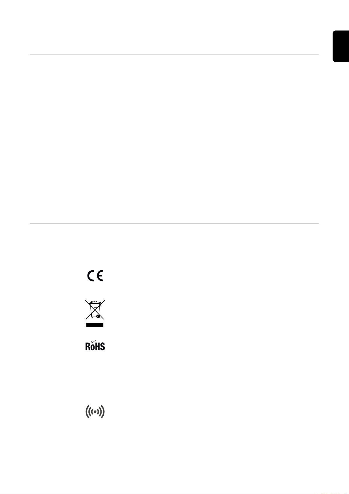
CE mark
The devices conform to all the requisite and relevant standards and guidelines
that form part of the relevant EU directive, and are therefore permitted to display the CE mark.
WEEE mark
To comply with Directive 2012/19/EU of the European Parliament on Waste
Electrical and Electronic Equipment and its implementation as national law,
electrical equipment that has reached the end of its life must be collected separately and returned to an approved recycling facility.
RoHS marking
The product is compliant with the relevant EU Directive on the Restriction of
(the use of certain) Hazardous Substances in electrical and electronic equipment.
Symbols on front of the device:
Card reader
Symbol in relief in the housing of the Wattpilot. The symbol marks the location
of the internal RFID card reader where ID chips can be authenticated or
taught-in or the Wattpilot can be reset using the reset card.
9
Eco Mode
This symbol indicates operation in Eco Mode; the first LED lights up white.
Next Trip Mode
This symbol indicates operation in Betrieb im Next Trip Mode; the second LED
lights up white.
Scope of supply
NOTE!
Only use original miniature fuses and original adapter sets.
Device safety can only be guaranteed with an original miniature fuse. Common glass
tube fuses can shatter.
The CEE plugs of the adapter set differ from those of other suppliers due to their design
with a reed contact.
Use original miniature fuses.
▶
Use original adapter sets.
▶
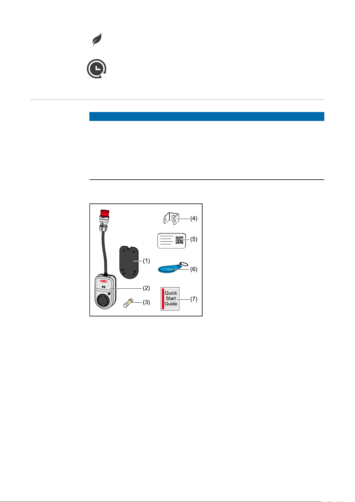
Fronius Wattpilot Go 11 J/22 J
(1) Mounting bracket, incl. screws and
dowels
(2) Wattpilot Go 11 J or Wattpilot Go
22 J
(3) Miniature fuse (only use original
miniature fuses)
(4) Anti-theft device
(5) Reset card
(6) ID chip
(7) Quick Guide
10
Optional
- Type 2 cable, 32 A, 22 kW, 5 m (item number 4,240,180)
- ID chips, 10 pieces (item number 4,240,181)
- Mounting plate Go, additional mounting bracket (item number 4,240,182)
- Adapter set Go 22 (item number 4,240,183), CEE adapter 32 A to
- CEE plug red 16 A (3-phase)
- CEE plug blue 16 A, camping plug (1-phase)
- Earthed plug 16 A (household socket)
- Adapter set Go 11 (item number 4,240,184), CEE adapter 16 A to
- CEE plug red 32 A (3-phase)
- CEE plug blue 16 A, camping plug (1-phase)
- Earthed plug 16 A (household socket)
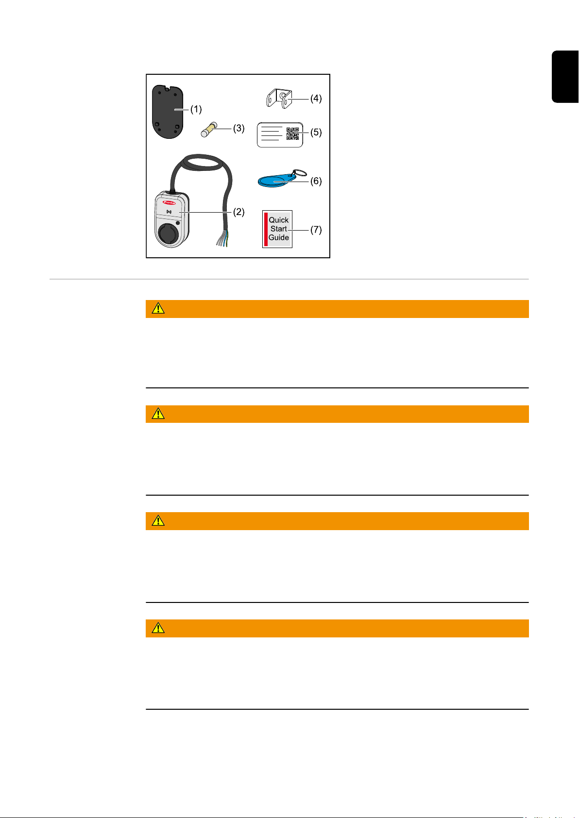
Fronius Wattpilot Home 11 J
Safety
(1) Mounting bracket, incl. screws and
dowels
(2) Wattpilot Home 11 J
(3) Miniature fuse (only use original
miniature fuses)
(4) Anti-theft device
(5) Reset card
(6) ID chip
(7) Quick Guide
WARNING!
Danger due to incorrect operation and incorrectly performed work.
This can result in serious injury and damage to property.
Read and understand this document.
▶
Read and understand all the Operating Instructions for the system components, es-
▶
pecially the safety rules.
EN
WARNING!
Danger from electromagnetic fields (EMF) for persons with pacemakers and defibrillators!
This can result in serious injury.
Persons with pacemakers must maintain a distance of at least 60 cm.
▶
Persons with defibrillators must maintain a distance of at least 40 cm.
▶
WARNING!
Danger due to open or damaged housing!
This can result in severe personal injury and damage to property due to high voltage
and/or sparking.
Do not use the device if the housing is damaged or open.
▶
Send in the device for repair.
▶
WARNING!
Danger from loose parts in the housing!
This can result in severe personal injury and damage to property due to high voltage
and/or sparking.
Do not use the device if there are loose parts in the housing.
▶
Send in the device for repair.
▶
11

WARNING!
Danger due to cables!
Damaged or exposed cables can result in severe personal injury and damage to property.
Do not use the device if the cables attached to or plugged into the device are dam-
▶
aged.
Adequately support the weight of the device and the charging cable.
▶
Lay the charging cable securely, provide mechanical relief for the cables.
▶
Lay the charging cable securely to avoid the risk of tripping over the charging cable.
▶
WARNING!
Danger due to wet or dirty connectors!
Charring caused by prolonged usage can result in severe personal injury and damage to
property.
Only mount the device vertically.
▶
Dry wet connectors in a de-energised state.
▶
Clean soiled connectors in a de-energised state.
▶
WARNING!
Danger from gassing vehicle batteries!
This can result in serious injury.
Only use in well-ventilated areas.
▶
WARNING!
Danger from driving away with the charging cable connected!
This can result in severe personal injury or damage to property.
Disconnect the charging cable from the electric vehicle before driving away.
▶
Do not bypass the safety device of the electric vehicle.
▶
WARNING!
Danger due to excessive load!
This can result in severe personal injury or damage to property.
The load when operating the device with an earthed plug must not exceed 10 A.
▶
The earthed socket outlet must be suitable for continuous operation at 10 A.
▶
Check for heat generation after each use.
▶
The device and the sockets must not overheat.
▶
CAUTION!
12
Danger due to excessive charging current!
Fires or damage to the in-house installation may result.
Observe the maximum permissible current at the connected socket.
▶
If the maximum charging current is not known, charge with the lowest possible char-
▶
ging current.
An automatic reduction of the charging current to 16 A by plugging in the adapter is
▶
only possible in conjunction with the original adapters.
Only use original adapters.
▶

CAUTION!
Danger due to heat generation on the device!
The build-up of heat can lead to lasting damage and even fire.
Never cover the device during charging.
▶
Unwind the cable completely from a cable drum.
▶
Observe the correct installation position.
▶
Never pull the plug out of the plug connection by the cable!
Observe the specifications of the grid operator regarding 1‑phase charging and the
asymmetrical network load that may result.
The device has a built-in residual current protection module with residual current detection (30 mA AC and 6 mA DC). This means that no upstream type B RCD is required. A
separate type A RCD and an automatic circuit breaker must be connected upstream for
each Wattpilot.
The device may only be operated at the following connections:
- CEE red 32 A, 3-phase, 400 V (Wattpilot Go 22 J)
- CEE red 16 A, 3-phase, 400 V (Wattpilot Go 11 J)
- With original adapters:
- CEE red 16 A, 3-phase, 400 V (Wattpilot Go 22 J)
- CEE red 32 A, 3-phase, 400 V (Wattpilot Go 11 J)
- CEE blue 16 A, 1-phase, 230 V
- Earthed plug 16 A, 1-phase, 230 V
EN
In case of defective adapters or defective CEE plugs, send the device in for repair.
Suitable inverters Compatibility with the connected devices, suitable data communication and a Fronius
Smart Meter at the feed-in point are prerequisites for using some Wattpilot functions (e.g.
PV surplus).
Suitable Fronius inverters
- Fronius GEN24
- Fronius Symo Hybrid
- Fronius SnapINverter (except light versions)
- Fronius IG*
- Fronius IG Plus*
- Fronius IG TL**
- Fronius CL*
*Requirement:
- Fronius Smart Meter
- Fronius Datamanager 2.0 (item number 4,240,036,z), or
- Fronius Datamanager Box 2.0 (item number 4,240,125)
**Requirement:
- Fronius Datamanager Box 2.0 (item number 4,240,125)
Suitable generators from third-party manufacturers
Suitable generators can be, for example, inverters or wind power plants. A prerequisite
for compatibility with external generators is that no other self-consumption controllers
(with e.g. battery, Power-2-Heat) are operated in parallel. This can lead to PV optimisation malfunctions. The proportion of energy consumed by other loads is not taken into
account in the Fronius Solar.wattpilot app, as the power is only known at the grid connection point.
13

Requirement:
- Fronius Smart Meter (at the feed-in point)
- Fronius Datamanager Box 2.0 (item number 4,240,125)
For more information, see Data communication with the inverter.
14
Controls and indicators
(1)
(2)
(3)
(4)
(5)
(6)
(7)
(8)
(10)
(9)
EN
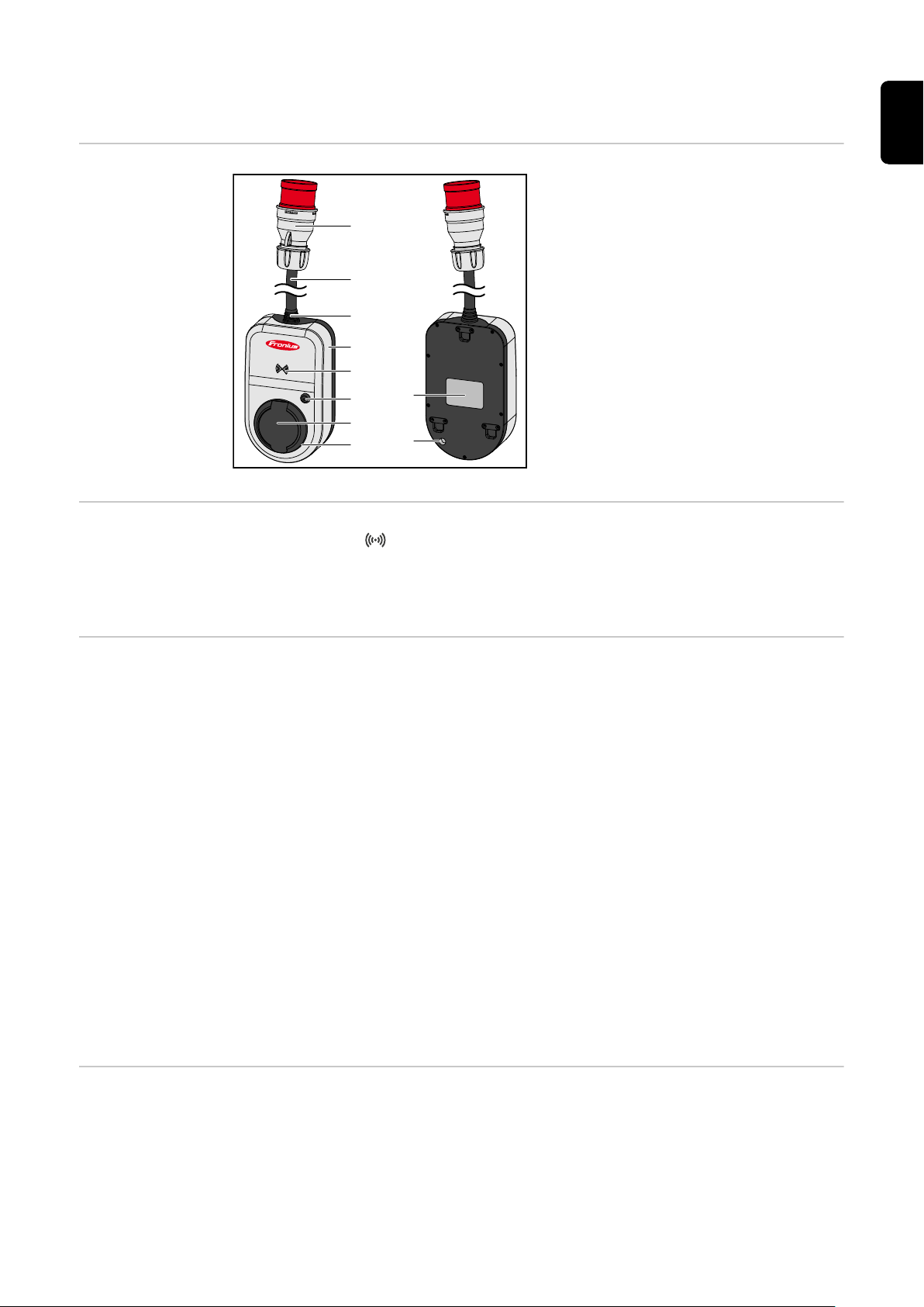
Product overview
Card reader
(1) CEE plug
(2) Connection cable
(3) Strain-relief device
(4) Housing
(5) Card reader
(6) Pushbutton
(7) Type 2 junction box
(8) LED ring
(9) Rating plate
(10) Miniature fuse (only use original
miniature fuses)
Behind the symbol is the card reader for reading ID chips and the reset card.
The card reader uses RFID (radio-frequency identification). RFID is the transmitter‑receiver technology for automatic and contactless identification with radio waves.
Pushbutton functions
ID chip The ID chip can be used to personalise access to the Fronius Wattpilot. The ID chip is
By pressing the pushbutton, the level of charging current can be adjusted or the operating mode can be changed.
Press briefly (less than 0.5 s)
Briefly pressing the pushbutton changes the operating mode. The charging modes are
Eco Mode and Next Trip Mode. The selected charging mode (see Different charging
modes) is indicated by the LED status indicator (see LED status indicator).
Press and hold (more than 2.0 s)
Pressing and holding (min. 2 seconds) the pushbutton repeatedly changes the preset
charging current (in amperes). The level of the set charging current is indicated by the
LED status indicator (see LED status indicator).
The level of the preset charging current can be adjusted in the app (see Current level).
Standard settings
- Fronius Wattpilot Go 11 J/Home 11 J: 6 A, 10 A, 12 A, 14 A, 16 A
- Fronius Wattpilot Go 22 J: 10 A, 16 A, 20 A, 24 A, 32 A
used for authentication and for recording user-specific charging amounts.
In the app settings, authentication for charging can be activated under "Access management" and "Authentication required" (see Access management). Charging with authentication activated can be carried out after scanning the supplied ID chip or by providing
15
confirmation in the app. To scan, hold the ID chip directly in front of the card reader of the
Wattpilot.
Each ID chip can be assigned a name in the app under "ID chips". The stored charging
amount per ID chip can be viewed in this menu (see ID chips).
No authentication is required in order to assign the charging amount to the ID chips.
Reset card The reset card resets all settings (e.g. access management, WLAN and LED settings) to
the factory settings. The taught-in ID chips and the corresponding charging amounts
continue to be stored.
The following information is printed on the reset card.
- "Serial number" - serial number of the Wattpilot
- "Hot spot SSID" - WLAN network name of the Wattpilot
- "Hot spot key" - WLAN password of the Wattpilot
- "QR code" - key to connect the app to the Wattpilot hot spot
Resetting the Wattpilot
Hold the reset card in front of the card reader.
1
All LEDs briefly light up red.
2
LED status indicator
NOTE!
Keep the reset card safe!
The reset card contains all access data.
TIP: Keep the reset card in the car.
▶
The LED status indicator on the Wattpilot indicates whether the system is switched on
and the current system status of the Wattpilot. One LED represents one ampere (1 A). A
maximum of 32 A is displayed.
The first two LEDs indicate the currently active operating mode. If these do not light up
white, the Wattpilot is in standard mode - charging takes place with the maximum set
current without taking surplus PV electricity and flexible electricity tariffs into account.
Eco Mode
The Wattpilot is in Eco Mode.
- The first LED lights up white.
- The first LED flashes orange (see chapter Status
Codes).
- The first LED flashes red (see chapter Status Codes).
Next Trip Mode
The Wattpilot is in Next Trip Mode.
16
- The second LED lights up white.
- The second LED flashes orange (see chapter Status
Codes).
- The second LED flashes red (see chapter Status
Codes).
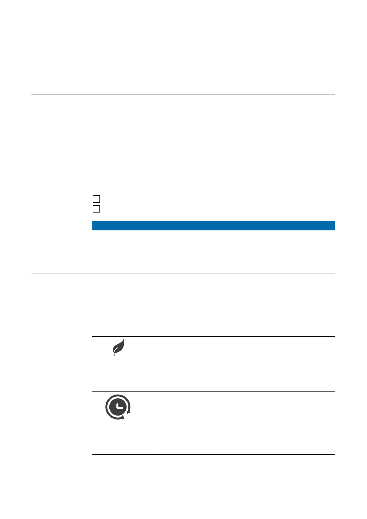
Starting
The Wattpilot is starting up or restarting.
- The LEDs light up in rainbow colours.
Ready
The Wattpilot is ready for operation. The number of LEDs that
light up indicates the set charging current.
Each LED represents 1 ampere (A). A maximum of 32 A can
be displayed, whereby the first two LEDs are reserved for the
charging modes.
- A few blue LEDs light up = low charging current (e.g.
10 LEDs = 10 A).
- Several/all blue LEDs light up = high charging current
(e.g. 32 LEDs = 32 A).
Enable
The Wattpilot must be activated via the app or an ID chip.
EN
- The LEDs light up blue, four pairs of LEDs run in a
quarter circle from the top and bottom towards each other.
Waiting
The Wattpilot is waiting for cheap electricity from a photovoltaic system or electricity provider, or the charging timer is active.
- The LEDs flash blue in the number of amperes set.
Wait for car
The Wattpilot recognises the connected vehicle and the set
charging parameters. Charging has been enabled by the charging station but not yet started by the car.
- A few yellow LEDs light up when the charging current is
low.
- Several/all yellow LEDs light up when the charging current is high.
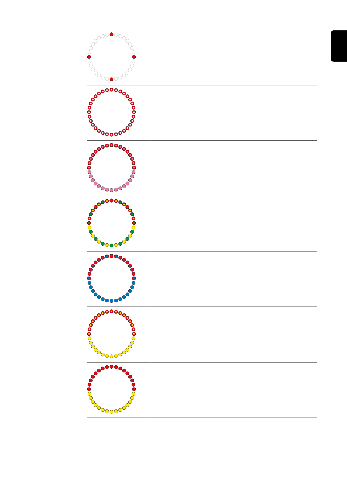
17

1-phase charging
The Wattpilot is carrying out 1-phase (230 V) charging with
low to high charging current.
- One series of blue LEDs moves in a clockwise direction.
- The level of charging current is indicated by the number
of LEDs and the speed of rotation.
3-phase charging
The Wattpilot is carrying out 3-phase (400 V) charging with
low to high charging current.
- Three series of blue LEDs move in a clockwise direction.
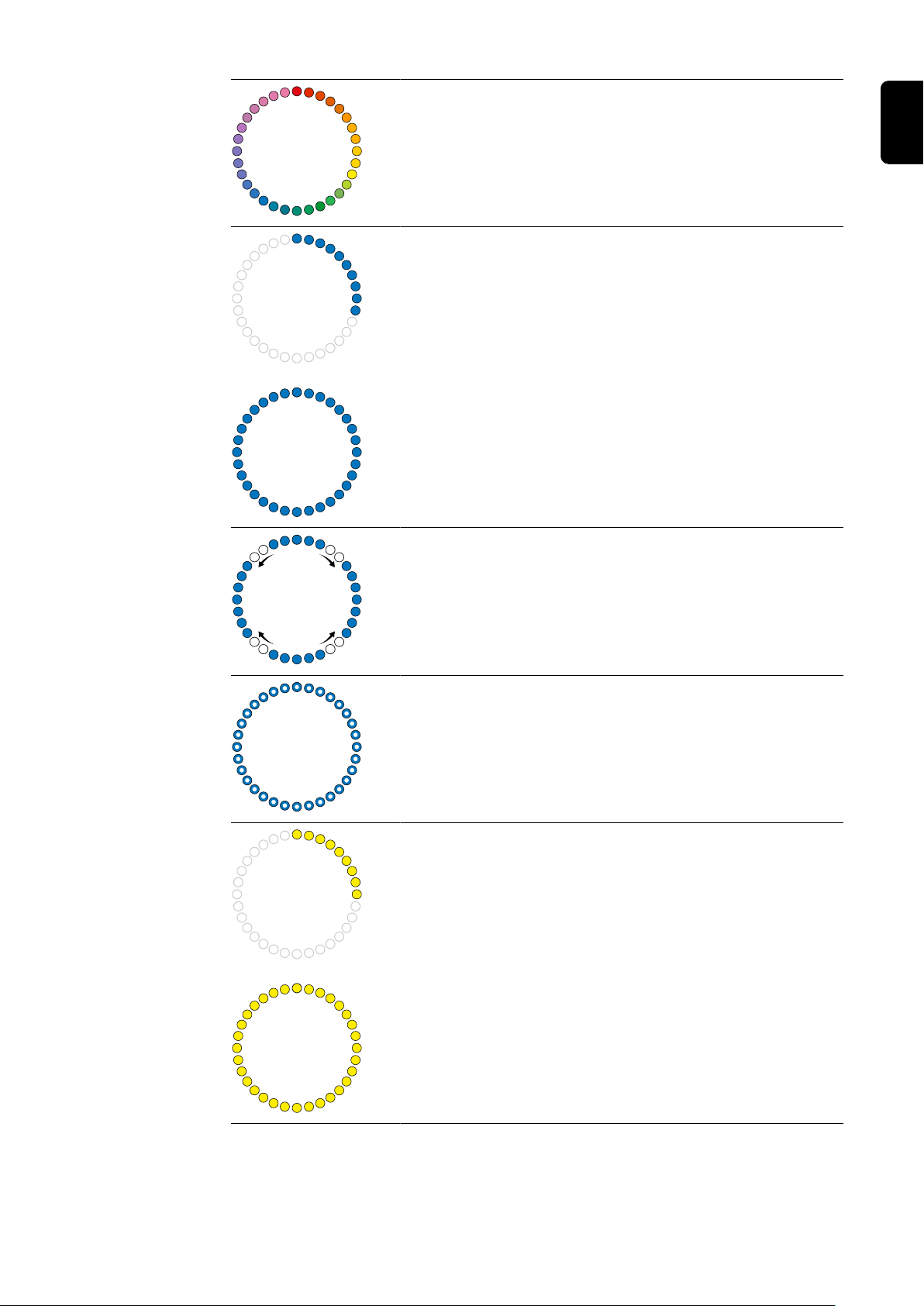
Charging finished
The charging process is complete.
- All LEDs light up green.
ID chip detected
The Wattpilot has detected an authorised ID chip.
- Five LEDs light up green.
Invalid value
Wattpilot displays an invalid input. Pressing the push button
was not permitted or an ID chip was detected but not authorised.
- Five LEDs light up red.
18
Earthing test deactivated
The earthing test is deactivated.
- Four LEDs light up at 3, 6, 9 and 12 o'clock.
Internal communication fault
The Wattpilot displays an internal communication error. The
error code is displayed in the app. For more information, see
Status Codes.
- All LEDs flash red.
Residual current detected
The Wattpilot has detected a residual current (≥ 6 mADC or ≥
30 mAAC). Restart the Wattpilot. For more information, see
Status Codes.
- The LEDs light up pink, the LEDs at the top flash red.
Earth fault detected
The earthing of the supply line to the Wattpilot is faulty. Check
the earthing of the supply line. For more information, see
Status Codes.
EN
- The LEDs light up green and yellow, the LEDs at the top
flash red.
At least one phase of the power supply is missing
The phase(s) of the supply line to the Wattpilot has/have
failed. Check the phase(s) of the supply line. For more information, see Status Codes.
- The LEDs light up blue, the LEDs at the top flash red.
Temperature too high
The temperature of the Wattpilot is too high. The charging current is reduced. For more information, see Status Codes.
- The LEDs light up yellow, the LEDs at the top flash red.
Unlocking or locking error
Unlocking or locking has failed. The unlocking or locking attempt is repeated at 5-second intervals. For more information,
see Status Codes.
- The LEDs light up red at the top and yellow at the bottom
for 1 second.
19

Update
The Wattpilot firmware is being updated. The update can take
several minutes. Do not unplug the charging station.
- All LEDs flash pink, the progress of the update is indicated by yellow LEDs.
Update successful
- The LEDs light up alternately pink and green.
Update failed
- The LEDs light up alternately pink and red.
Reset card detected
The Wattpilot has detected the reset card and the settings are
reset.
- All LEDs light up red for 2 seconds.
20

Functions
Overview The Wattpilot can be used like any other charging station. For start-up, the charging
cable must be plugged in and the Wattpilot starts charging. By pressing the pushbutton
(see Pushbutton functions), it is possible to switch between the charging modes (see
Different charging modes) and change the level of charging current (see Current
level).
EN
Phase
changeover
PV surplus
The Fronius Wattpilot can automatically switch between 1‑phase and 3‑phase charging.
The automatic phase changeover enables charging with a low start-up power (1‑phase
with 1.38 kWh) in the case of a PV surplus. In addition, 1‑phase charging has the advantage that the charging power can be regulated in smaller increments (0.23 kW) and a
small PV surplus can be used more efficiently. As 1‑phase charging is limited by the car,
it makes sense to switch to 3‑phase charging at a higher PV surplus.
The phase changeover can be set automatically or manually (see PV surplus).
NOTE!
Do not exceed the phase‑load imbalance!
Select the phase changeover point in such a way that the maximum permissible
phase‑load imbalance is not exceeded.
NOTE!
A minimum charging time of 5 minutes is stored.
To prevent permanent switching of the relays and to increase the service life of the Wattpilot, a minimum charging time of 5 minutes is stored.
The surplus energy of a PV system (photovoltaic system) can be used. The prerequisites
for this are a compatible inverter in the same network as the Wattpilot and a Fronius
Smart Meter (for more information, see Data communication with the inverter).
Setting limit values ensures that the available PV surplus power is distributed to the
loads. The limit values created allow an energy storage system to be sufficiently charged
or the energy to be stored in the form of hot water before the surplus PV power is used
to charge a vehicle.
NOTE!
PV surplus regulation.
One Wattpilot per photovoltaic system.
The PV surplus regulation works with one Wattpilot per photovoltaic system.
▶
If several Wattpilots are connected to one inverter, "Use PV surplus" may only be ac-
▶
tivated on one Wattpilot. For all other Wattpilots, "Use PV surplus" must be deactivated (for more information, see Cost optimisation).
It is possible to set a start-up power level (specified in kW). This must be reached by
the photovoltaic system before the Wattpilot starts charging the car with the minimum
current.
21

It is possible to set a 3‑phase power level (specified in kW). This must be reached by
the photovoltaic system before the Wattpilot switches from 1‑phase to 3‑phase charging.
The settings for the start-up power level and 3‑phase power level can be made under
Cost optimisation in the Fronius Solar.wattpilot app.
The power level can only be regulated in increments of 1 ampere. The table below lists
the charging current in amperes (A) and the corresponding charging power for 1‑phase
and 3‑phase charging in kilowatts (kW). 1-phase in 0.23 kW increments, 3-phase in
0.69 kW increments. The values are based on the assumption that the voltage is exactly
230 or 400 V.
- Example: The charging current is increased by 1 A to 7 A.
- 1‑phase: 1.38 kW + 0.23 kW = 1.61 kW
- 3‑phase: 4.14 kW + 0.69 kW = 4.83 kW
Charging current (A)
1‑phase (kW) 1.38 1.84 2.3 2.76 3.22 3.68 4.6 5.52 7.36
3‑phase (kW) 4.14 5.52 6.9 8.28 9.66 11 13.8 16.56 22
6 8 10 12 14 16 20 24 32
Example
22
Photovoltaic generation
Electric vehicle
The figure illustrates the behaviour of the Wattpilot with a set start-up power level of
1.38 kW and a 3‑phase power level of 4.14 kW. If the PV surplus is less than 1.38 kW,
the vehicle is not charged.
If the PV surplus is between 1.38 and 4.14 kW, the Wattpilot regulates the charging
power in0.23 kWincrements.
If the PV surplus is above 4.14 kW, the Wattpilot switches from 1‑phase charging to
3‑phase charging and regulates the charging power in 0.69 kWincrements.

NOTE!
The minimum charging power of electric vehicles is usually 1.38 kW.
In the case of smaller photovoltaic systems, it may make sense to set the start-up power
level below 1.38‑kW so that sufficient energy is charged. The electricity that is not
covered by the photovoltaic system, however, is drawn from the grid. This results in a
power mix of self-consumption and grid supply.
A start-up power level below 1.38 kW results in a power mix.
▶
Charging with PV surplus can be activated and adjusted in the Fronius Solar.wattpilot
app (see Cost optimisation).
Priorities in the system between battery, Ohmpilot and Wattpilot
The priority of the Wattpilot can be influenced via the "PV battery limit value" and "Ohmpilot limit value" settings in the Fronius Solar.wattpilot app (see chapter Cost optimisa-
tion). Depending on the level of the selected limit values, it is possible to define under
which conditions the charging of the electric vehicle starts. The temperature limit value of
the Ohmpilot can only be used if a temperature sensor is connected to the Ohmpilot. To
set the Wattpilot priority, the energy management priority settings on the website for the
inverter must also be taken into account.
NOTE!
If no temperature sensor is connected to the Fronius Ohmpilot, a temperature of 0 °C is
assumed. If the Wattpilot is to be prioritised over the Ohmpilot, set the "Ohmpilot limit
value" to 0 °C. In the event of a sensor break, the Ohmpilot is supplied with power before
the Wattpilot.
EN
Example: Charging the electric vehicle first
The electric vehicle must always be charged with PV surplus before the battery and the
Ohmpilot. In the Solar.wattpilot app, the limit value for the battery is set to 0% and the
limit value for the Ohmpilot is set to 0 degrees. The electric vehicle is immediately
charged with PV surplus, regardless of the state of charge of the battery or the temperature of the Ohmpilot.
- System with inverter, Wattpilot, battery and Ohmpilot
Priority in the inverter Wattpilot Battery** Ohmpilot
Battery** > Ohmpilot Priority 3 until SOC*
and temperature limit
value reached, then 1
Ohmpilot > Battery** Priority 3 until SOC*
and temperature limit
value reached, then 1
- System with inverter, Wattpilot and Ohmpilot
Priority in the inverter Wattpilot Ohmpilot
Ohmpilot Priority 2 until temper-
Priority 1 until SOC*,
then 2
Priority 2 until SOC*,
then 3
ature limit value
reached, then 1
Priority 2 until temper-
ature limit value
reached, then 3
Priority 1 until temper-
ature limit value
reached, then 2
Priority 1 until temper-
ature limit value
reached, then 2
- System with inverter, Wattpilot and battery
23

Priority in the inverter Wattpilot Battery**
Flexible electricity tariff
Battery** Priority 2 until SOC*,
then 1
*SOC - State of Charge of the stationary battery
**Fronius-compatible DC coupled battery
NOTE!
The component with the highest priority in the inverter is taken into account.
If, for example, a battery in the inverter is prioritised higher than an Ohmpilot and the battery limit value is set to 50% and the Ohmpilot limit value is set to 50 °C, the Wattpilot will
start charging when the battery reaches 50% SOC. The Ohmpilot is not supplied with energy until the electric vehicle and battery are fully charged.
IMPORTANT!
The energy management with the digital outputs (I/Os) on the Fronius inverter must not
be used for load management of the Wattpilot! The priorities of the loads are not clearly
assigned.
The flexible electricity tariff can be used if electricity is purchased from electricity retailers
and charged for hourly via the electricity exchange, e.g.
- Lumina Strom hourly (available in Germany, as at 01/03/2021) or
- aWattar hourly (available in Austria and Germany, as at 01/03/2021).
Priority 1 until SOC*,
then 2
The Wattpilot queries the retailer tariffs directly via the Internet. It is possible to specify a
price threshold (Eco Mode price limit) below which charging starts. This is the pure electricity price, without network charges or other fees.
Example
The following figure shows the electricity price of an electricity retailer (Lumina Strom
hourly, aWattar hourly) over 24 hours. The hourly tariffs are retrieved from the electricity
exchange at a specific time for the next day.
Information regarding electricity retailers with a flexible electricity tariff can be
found under
- Lumina Strom hourly (as at 01/03/2021)
- aWattar hourly (as at 01/03/2021)
24

Different charging modes
Standard mode In standard mode, charging takes place at the preset amperage (e.g. 16 A). The level of
charging current can be changed in increments by pressing the pushbutton on the Wattpilot. In the app (see Current level), the charging current can be adjusted in 1 ampere
increments.
In standard mode, no operating mode LEDs light up.
Whereas charging at a low charging current is gentle, charging at a high charging current
enables rapid charging. If necessary, charging is carried out with electricity sourced from
the grid.
NOTE!
Standard mode
Standard mode is the standard setting of the Wattpilot; no LEDs light up white. In this
charging mode, the PV surplus and the flexible electricity tariff are not taken into account.
No further settings are required for standard mode.
▶
EN
Eco Mode In Eco Mode, a vehicle is only charged when low-cost electricity is available. Charging
can either take place with cheaply purchased electricity (see Flexible electricity tariff)
or surplus energy produced by the photovoltaic system (see PV surplus). There is no
guarantee that charging will occur.
Prerequisite
Charging in Eco Mode is only possible if PV surplus and/or a Flexible electricity tariff
is activated under PV surplus in the Fronius Solar.wattpilot app.
NOTE!
Charging not possible.
If there is no surplus generated power or cheap electricity available, charging is not carried out in Eco Mode.
Change mode for guaranteed charging.
▶
Enable
Eco Mode can be configured in the app under Cost optimisation and activated by
pressing the pushbutton (< 0.5 s) or via the Fronius Solar.wattpilot app.
NOTE!
The battery of the photovoltaic system is discharged first!
If the system contains a stationary battery, the battery of the photovoltaic system is discharged when the electricity price falls below the threshold before mains current is
drawn.
25

Example
Photovoltaic generation
Electric vehicle
Household consumption
In Eco Mode, the electric vehicle is connected to the Wattpilot at around 15:00, as although a fixed additional range for the electric vehicle is not necessary, cheaper electricity is to be used for charging. In the Fronius Solar.wattpilot app, the PV surplus and/or
flexible electricity tariff must be activated and set under Cost optimisation. Household
consumption is covered by photovoltaic generation and the electric vehicle is charged
with the PV surplus. Charging takes place using the PV surplus until around 20:00.
Between 02:00 and 05:00, the electricity price falls below the defined price limit. The
electric vehicle is charged with cheap electricity during this period.
Charging in Eco Mode
PV surplus Price limit Wattpilot
No No No charging
No Yes Max. charging
Yes No Charging with PV surplus
Yes Yes Max. charging
Next Trip Mode In Next Trip Mode, a vehicle is charged as cheaply as possible until the end of the self-
selected time with the set charging amount. The time charging starts is selected in such
a way that the desired charging amount is charged at least one hour before the charge
end. Charging takes place in the cheapest cost window. The PV surplus and flexible
electricity tariff settings are taken into account. If the "Stay in Eco Mode" function (for activation see Next Trip Mode) is activated, the Wattpilot continues charging with low-cost
energy after the set charging amount has been reached.
The set charging amount is charged in addition to the charging amount available in the
electric vehicle. The charging amount is specified in kilometres and calculated on the
basis of an average consumption (18 kWh/100 km). External conditions (season, driving
26

speed, car model, etc.) may cause deviations in the actual range. When setting the charging amount, the actual state of charge of the electric vehicle battery is not read out.
The mode can be set under "Next Trip Mode" in the Fronius Solar.wattpilot app (see
Next Trip Mode).
After activating the mode, charging is started briefly to calculate a charging schedule taking into account the possible charging power. If no flexible electricity tariff is activated,
charging is started at the latest possible time in order to charge with a possible PV surplus and to conserve the battery of the electric vehicle. If no time is provided for the calculation of the charging schedule, charging starts immediately.
NOTE!
Internet connection required if a flexible electricity tariff is activated!
If the flexible electricity tariff is activated in Next Trip Mode and there is no connection to
the electricity provider's data, the Next Trip Mode LED flashes red. Charging starts in order to reach the set charging amount.
If the charging cable is disconnected and reconnected while Next Trip Mode is activated,
the calculation is repeated and the set charging amount is charged in addition to the existing charging amount. Changes to the settings of the Fronius Solar.wattpilot app result
in a recalculation of the charging schedule. If the change is made during Next Trip Mode
charging, the range charged up to this point is added to this.
EN
If "Stay in Eco Mode" is activated, the cost optimisation settings are also taken into account in Next Trip Mode.
NOTE!
The battery of the photovoltaic system is discharged first!
If the system contains a stationary battery, the battery is discharged before mains current
is drawn.
NOTE!
Orange flashing LEDs if the charging amount cannot be reached or stored!
If the set charging amount cannot be charged in the specified time or if the car cannot
store the set charging amount, the LEDs flash orange.
Reduce the charging amount or extend the charging time.
▶
Example
27

Photovoltaic generation
Electric vehicle
Household consumption
The daily journey to work and back home is 50 km and must start at 08:00. In the Fronius Solar.wattpilot app, the kilometres and the departure time must be entered once under Next Trip Mode. 18 kWh is used as the basis for the calculation of 100 km. The electric vehicle is plugged in and charged at approximately 15:00. If PV surplus is available,
charging is carried out with PV surplus. The remaining charging amount is guaranteed to
be charged in the electric vehicle at the latest possible time. The charge is calculated in
such a way that it is completed at the latest one hour before departure.
NOTE!
If there is sufficient energy in the electric vehicle, it is better to use Eco Mode zu.
If the electric vehicle is sufficiently charged, Eco Mode is the better choice.
Change to Eco Mode (see Eco Mode).
▶
28

Installation and commissioning
29

30

Installation location and position
EN
Choice of location
The following criteria must be taken into account when choosing a location.
The Wattpilot is suitable for outdoor operation without direct sunlight.
The Wattpilot is suitable for operation in a well-ventilated indoor area.
Do not operate the Wattpilot in areas with increased danger as a res-
ult of ammonia gases.
The Wattpilot is suitable for operation indoors and outdoors.
Environmental conditions
- Indoors and outdoors, no direct sunlight, suspended
- Ambient temperature: -25 °C to +40 °C
- Humidity: 5% to 95%
- Height above sea level: 0 m to 2000 m
Installation position
CAUTION!
Beware of warping of the mounting bracket on uneven surfaces.
An uneven surface can cause the mounting bracket to warp, making it impossible to attach the Wattpilot.
Select a suitable location on an even surface.
▶
The Wattpilot is designed to be installed vertically on a vertical, level
wall.
31

Do not install the Wattpilot horizontally.
Do not install the Wattpilot on a sloping surface.
Do not install the Wattpilot on a sloping surface with the connection fa-
cing down.
CAUTION!
Danger due to heat generation on the device!
The build-up of heat can lead to lasting damage and even fire.
Never cover the device during charging.
▶
Unwind the cable completely from a cable drum.
▶
Observe the correct installation position.
▶
NOTE!
The type 2 plug is not waterproof.
Water can penetrate when the Wattpilot is mounted horizontally.
Mount the Wattpilot vertically.
▶
32

Wall mounting
EN
Mounting the
Wattpilot on the
wall
When mounting the mounting bracket, ensure that it is not warped or deformed. The following illustrations may differ slightly from the actual product; the Wattpilot Home 11 J
does not have a mains plug.
1 2
3 4
33

Connecting the Wattpilot
General information
Installing the
Wattpilot HOME
11 J
CAUTION!
Installation and commissioning may only be performed by a qualified electrician.
Requirements for the qualification of electricians - knowledge and observation of the 5
safety rules for working on electrical systems.
Disconnect.
▶
Ensure the device cannot be switched back on.
▶
Ensure the system is no longer live.
▶
Carry out earthing and short-circuiting.
▶
Cover nearby live components or make them inaccessible.
▶
NOTE!
Duty to inform the grid operator!
Check with the grid operator whether there is a duty to inform in the country of des-
▶
tination and, if necessary, report the Wattpilot to the grid operator.
When installing the Wattpilot HOME 11 J, the mains cable must be installed by a qualified person in accordance with national standards. The fuse protection for the mains lead
must be dimensioned in accordance with the device technical data.
WARNING!
Danger from mains voltage!
An electric shock can be fatal.
Always make sure the circuit is disconnected and de-energised before carrying out
▶
any connection work.
The connection may only be established by an authorised electrician.
▶
Observe the national standards.
▶
1
Disconnect the circuit from the power supply before carrying out any connection
work.
34

22222
2
2
2
Have the 5‑pin mains cable connected by
an authorised electrician in accordance
with national standards and safety rules.
Depending on the available mains supply
type, opt for a 1- or 3-phase connection.
NOTE!
For 1-phase operation, phase L1 must be used.
To supply power to the Wattpilot, phase L1 must be connected. The unused phases
▶
L2 and L3 must be isolated (contact protection)!
EN
Backup power
mode
NOTE!
It is advisable to connect the Wattpilot outside the backup power loads of a photovoltaic system!
If the charging current per phase cannot be covered by the backup power, the Wattpilot
must be connected outside the backup power loads. A Fronius inverter is required for
backup power mode.
If the Wattpilot is connected in the backup power circuit of a photovoltaic system and the
total current of one phase is exceeded as a result, the inverter switches off the backup
power. The electric vehicle must be unplugged and the backup power acknowledged
(see inverter Operating Instructions).
IMPORTANT!
It is important to check whether the electric vehicle allows charging at 53 Hz.
Start-up Start up the permanently installed Wattpilot Home 11 J from step 2.
35

1
Set the desired charging current by pressing the pushbutton. One illuminated LED
2
on the LED ring represents one ampere (1 A). A maximum of 32 A (Wattpilot Go
22 J) or 16 A (Wattpilot Go 11‑J or Wattpilot Home 11 J) is displayed. The level of the
charging current can be individually adjusted in the app between 6 and 16 or 32 A
(see chapter Current level)
3
Connect the CEE plug to a suitable socket
directly or with a suitable adapter.
The LEDs light up in the rainbow colours
during an initial self-test. Afterwards, the
number of LEDs corresponding to the set
charging current light up blue.
Connect a Type 2 to Type 2/Type 1 charging cable to the Wattpilot and the car.
Stopping charging
During a test, all LEDs light up yellow.
The charging process is started with a
clicking sound from the Wattpilot and indicated by the switching of the LEDs.
For more information on LED status indicators, see chapter LED status indicator.
The vehicle is charging.
The charging process is terminated by the vehicle. This is normally the case when the
vehicle's battery is fully charged. By default, the charging cable remains locked to the
Wattpilot after charging is complete until the cable is disconnected from the vehicle (antitheft protection, see chapter Cable release).
Aborting the charging process prematurely
- In the vehicle via the "cable release" function
- In the app by clicking on "Stop" (see chapter Homepage).
36
NOTE!
The way in which the cable is released can be configured in the app.
If the power supply is interrupted, the charging cable remains locked in the Wattpilot for
reasons of theft protection. The cable release can be activated in the app under "Unlock
in case of power failure".
Restore the power supply to the Wattpilot to unlock the charging cable.
▶
Configure the cable release in the app.
▶

Data communication with the inverter
Charging with PV surplus (see PV surplus) is possible with a supported Fronius inverter
to which a primary Fronius Smart Meter is connected. As soon as an inverter is in the
network, the Wattpilot automatically connects once with the first inverter that is found.
Another inverter can be coupled via the Fronius Solar.wattpilot app (see Cost optimisa-
tion).
Prerequisites
- The inverter is supported and has a suitable data interface (see Suitable inverters).
- The Wattpilot and the inverter are in the same network.
- A primary Fronius Smart Meter (at the feed-in point) must be connected to the inverter. If there are several inverters with primary Fronius Smart Meters in the network, only one of them may be coupled.
EN
37

38

Fronius Solar.wattpilot app
39

40

Overview
General The Fronius Solar.wattpilot app can be used to start up, configure, operate, visualise and
update the Wattpilot. The app is available for Android™ (Android is a trademark of
Google LLC) and iOS®.
The app enables the Wattpilot to be accessed directly (see Setting up a hot spot) or
worldwide via the Internet (see Setting up the WLAN).
Download The Fronius Solar.wattpilot app is available on the respective platform depending on the
end device with which the Wattpilot is operated. The app can be updated on the respective platform.
Download the app via
EN
41

Connecting via WLAN
Launching the
app
Setting up a hot
spot
Open the Fronius Solar.wattpilot app on the end device and follow the Setup wizard.
1
Read and accept the terms of use.
2
Click on "Connect".
3
NOTE!
Request on iOS.
Access for the Fronius Solar.wattpilot app must be allowed for end devices with an iOS
operating system.
iOS settings > Privacy > Local network > Fronius Solar.wattpilot > Allow access to local
network
The Wattpilot permanently opens a hot spot.
Scan the QR code on the reset card or connect the end device to the WLAN hot spot
1
(the password can be found on the reset card) of the Wattpilot (e.g. Wattpilot_12345678).
Follow the further instructions in the app.
2
NOTE!
Setting up the
WLAN
Adding a Wattpilot
Request on Android.
The selected WLAN of the Wattpilot must remain connected despite the absence of an
Internet connection for end devices with an Android operating system.
Select WLAN and enter the password.
1
NOTE!
It can take up to 1 minute to establish the connection!
If the signal strength is low, a WLAN repeater must be installed, for example.
Follow the further instructions in the app.
2
New or connected Wattpilots can be added in the Fronius Solar.wattpilot app.
Click on the "+" symbol.
1
Click on "Add" for the connected Wattpilot.
2
Follow the further instructions in the app.
3
- See Setting up a hot spot
- See Setting up the WLAN
42

Charging
1
2
3
4
5
Homepage The figure below shows the "Charging" homepage of the Fronius Solar.wattpilot app.
(1) The "Select Wattpilot" page can be
accessed by tapping the app icon.
A new Wattpilot can be added by
pressing the "+" icon.
(2) The following views can be dis-
played in the main window:
- "Power"
- "Details"
- "Forecast"
(3) In the "Power" view, the current
charging current and the charging
time are displayed. The charging
process can be started and
stopped by tapping the circle. By
tapping the circular buttons below,
the pages for the "Mode", the set
"Charging current" or the "Next
Trip Mode" settings can be accessed.
(4) Details of the current charging pro-
cess are displayed under "Status"
and "Range".
(5) The following pages can be called
up:
- "Charging"
- "Settings"
- "Internet"
EN
Energy per user
Under "Range", a list showing the consumption of the registered ID chips can be called
43

up via "Energy per user". By entering "Total", the list can be downloaded as a .csv file.
The following data is displayed in the file:
- Number: Sequential number of the session.
A session is the period of time between connecting and disconnecting the charging
cable.
- Session ID: Unique identification number.
- ID chip: Indicates the registered ID chip. No entry if loaded without ID Chip.
- Proportion from Eco Mode [%]: Proportion of the charged energy from Eco Mode as
a percentage [%].
- Proportion from Next Trip Mode [%]: Proportion of the charged energy from Next
Trip Mode as a percentage [%].
- Start: Start date and time from which the charging cable is connected.
- End: End date and time when the charging cable is disconnected.
- Duration: Period of time during which the Wattpilot is in use.
- Charging time: Indicates the period of time during which energy was being charged
into the electric vehicle.
- Max. power [kW]: Indicates the maximum power in kilowatts [kW] reached during
charging.
- Max. current [A]: Indicates the maximum current in amperes [A] reached during
charging.
- Energy [kWh]: Indicates the charged energy in kilowatt hours [kWh].
- Proportion from PV [kWh]: Proportion of the charged energy in kilowatt hours [kWh]
provided by PV surplus.
- Proportion from battery [kWh]: Proportion of the charged energy in kilowatt hours
[kWh] provided by a stationary battery.
- Meter reading [kWh]: Indicates the total charged energy in kilowatt hours [kWh].
44

Settings
Current level Five different current levels can be set. The current levels are selected from Level 1
(gentle) to Level 5 (rapid) by pressing the push button on the Wattpilot. Adjust the desired levels by clicking in the respective field.
Lock current level selection
This setting can be used to lock the push button (key) on the Wattpilot. Locking the push
button prevents accidental changing of the current level.
Absolute maximum
This setting is used to adjust the maximum charging current of the Wattpilot. Higher charging currents can no longer be selected.
NOTE!
The infrastructure is not known!
If charging in an unknown infrastructure, always charge with the lowest charging current
(e.g. 6 A or 10 A).
Charge with the lowest charging current.
▶
EN
NOTE!
Increase the service life of the battery.
A slow charge with a low amperage is gentler on the battery of the electric vehicle. This
can extend the service life of the battery.
Charge with a low charging current.
▶
Next Trip Mode Charging is carried out as cheaply as possible using surplus PV current (see PV sur-
plus) and a flexible electricity tariff (see Flexible electricity tariff).
Under "Settings", click on the "Next Trip Mode" button.
1
Specify the "Minimum amount of charging" in kilometres (km) or kilowatt-hours
2
(kWh).
- 100 km correspond to 18 kWh as standard. The actual consumption over 100
km varies from vehicle to vehicle and can be adjusted under "Consumption over
100 km".
Enter the time by which charging must be complete.
3
Activating "Next Trip Mode"
- Directly on the Wattpilot by pressing the push button (see Pushbutton functions).
- In the app, under "Charging", click on the "Mode" button and activate "Next Trip
Mode".
Activating "Remain in Eco Mode"
After reaching the set range, the Wattpilot switches from Next Trip Mode to Eco Mode.
Charging continues with the Eco Mode settings.
Cost optimisation Under "Cost optimisation", the consideration of the electricity tariff (see Flexible electri-
city tariff) and the use of PV surplus (see PV surplus) can be activated. The settings
listed below can also be customised.
45

Use Lumina Strom / aWattar
Activation or deactivation of flexible electricity tariffs.
Eco Mode price limit
When a flexible electricity tariff is activated in Eco Mode, charging does not start until the
set electricity price is below this value. If the electricity price is above this value, charging
does not take place.
NOTE!
In Next Trip Mode, it is not this value that is taken into account but the most favourable
charging times in the available time period.
Use PV surplus
The Wattpilot uses the surplus PV energy for charging.
Inverter
Selection of a coupled inverter.
PV battery threshold
If a battery is installed in the photovoltaic system, a limit value can be set here. Below
the set value, the battery is charged as a priority. Above this value, the energy of the battery is used to charge the car. The SOC of the battery may still slowly increase.
Ohmpilot threshold
If a Fronius Ohmpilot is installed in the photovoltaic system, a limit value for the temperature can be set here. Below the set value, the available energy is prioritised for heating.
Above this value, the heating power of the Ohmpilot is used to charge the car. The temperature may still slowly increase.
NOTE!
To use the function with an available Fronius Ohmpilot, a temperature sensor must be
connected to the Ohmpilot.
PV surplus
In the advanced settings, a start-up power level can be set from which the PV energy is
used for charging. Electric vehicles require a certain minimum power in order to charge.
- Starting power level: If "0" is set, the Wattpilot will start charging even if no PV surplus is available.
In the case of Zero feed-in, no PV current is fed into the grid. If zero feed-in is activated
in the inverter, it must also be activated in the Wattpilot.
NOTE!
Priorities with zero feed-in activated.
If zero feed-in is activated, the prioritisation of system components cannot be guaranteed. PV optimisation control may be restricted.
Deviations may occur when using PV surplus, as electric vehicles are regulated in
stages. The following settings can be made under Control response:
- Prefer from grid: The Wattpilot prioritises consumption over feed-in from the grid.
- Default: The Wattpilot enables both consumption and feed-in.
- Prefer to grid: The Wattpilot prioritises feed-in over consumption from the grid.
46
Car
With intelligent charging, the charging process can be interrupted or the charging current
reduced in order to meet certain charging conditions. Car-specific settings must be specified for smooth smart charging.

NOTE!
The electric vehicle is not listed - select standard charging behaviour.
If the electric vehicle to be charged is not listed, no specific charging behaviour is known.
All defaults can be customised.
Select the standard charging behaviour.
▶
- Choose car: The optimised standard settings of different car models can be activated under "Select car".
- Minimum current: Some cars will not resume charging after an interruption. To prevent an interruption, the minimum charging current can be set.
- Forced charging interval: In the case of cost-optimised charging, the Wattpilot interrupts the charging process if the electricity price is too high. Some cars will not
tolerate interruptions and will not continue charging after prolonged interruptions to
the charging process. In this case, the charging process must be started regularly
for a short time.
- Allow charging pause: Some cars will not resume charging after an interruption.
Charging interruptions are prevented if this option is deactivated.
- Simulate unplugging: Some cars need to be disconnected for a while if there has
been an interruption during cost-optimised charging. This function simulates a disconnection before charging continues.
- Minimum charging time: Set the minimum time for which the car must be charged
after charging starts.
- Choose phase switch:
- Automatic: A power level can be set, from which 3‑phase charging takes place.
If "0" is set, the Wattpilot immediately starts 3‑phase charging.
- Only 1‑phase: There is 1 phase available for charging.
- Only 3‑phase: There are 3 phases available for charging.
- 3‑phase power level: Set a power level that must be reached by the photovoltaic
system before the Wattpilot switches from 1‑phase to 3‑phase charging. If the available power is greater than the set value, the Wattpilot immediately activates 3‑phase
charging. Automatic switching can be deactivated in the car settings.
EN
Charging timer The "Charging timer" setting limits charging to specific times. A start and end time must
be specified for this. Several time windows can be set. The following can be set:
- The time (start and end time) and
- The days of the week.
NOTE!
Verhalten bei aktiviertem Eco Mode or Next Trip Mode:
If charging is not allowed by the charging timer for a certain period of time, Eco Mode
and Next Trip Mode are also blocked for this period.
If the charging timer does allow charging in a certain period of time but the settings for
Eco Mode or Next Trip Mode are not met, charging will not occur.
Brightness Set LED brightness values. By activating "Switch off LEDs after 10 s in standby", the
LEDs on the device are switched off after 10 seconds in standby.
LED colours Customise LED colours.
Time zone Set the time zone. Activating "Automatic summer time changeover" automatically sets
the summer and winter time.
47

Access management
In the "Access management" menu, it is possible to set whether charging is started automatically or after confirmation.
Open
The charging process is started automatically after connecting the cables.
Authentication required
Charging will only start after confirming in the app or scanning the supplied ID chip. To
scan, hold the ID chip in front of the card reader on the Wattpilot. If authentication is successful, 5 LEDs light up green.
Cable release Standard mode
The charging cable at the charging station remains locked after completion of the charging process until the charging cable is disconnected from the vehicle (anti-theft protection).
Auto-unlock
The charging cable is only locked during charging. This allows another user to disconnect the cable when the car is full in order to use the Wattpilot.
Always locked
The cable on the Wattpilot is always locked and can only be removed by changing the
mode. This mode is intended for permanently installed systems (e.g. in the carport).
Unlock during power outage
If this function is activated, the charging cable is unlocked in the event of a power failure.
By default, the charging cable remains locked in the event of a power failure for reasons
of theft protection. To unlock the charging cable, the Wattpilot must be supplied with
power again.
Earthing test Activation or deactivation of the earthing test. It is necessary to deactivate the earthing
test in insulated grids in certain countries (e.g. Norway) where earthing cannot be detected.
ID chips Up to 10 ID chips can be used. The ID chip is used for authentication and for recording
user-specific charging amounts.
NOTE!
One ID chip can be taught in for several Fronius Wattpilots.
48

Learn ID chip
Place the ID chip on the card reader of the Wattpilot.
1
Click on "Teach in ID chip" in the app.
2
Renaming an ID chip
Tap the corresponding entry.
1
Enter the desired name and tap "Save".
2
NOTE!
The ID chips and the charging amount remain stored in the event of a reset.
Password The password protects against unauthorised access to the Wattpilot.
Password guidelines
- At least 10 characters
- At least three of the following four strings: Upper case letters, lower case letters,
numbers, special characters
- No umlauts (ä, ö, etc.)
- No paragraph sign (§)
EN
49

Internet
Firmware update The current firmware of the Wattpilot is loaded via the Internet. The "Internet" menu
shows which firmware version is installed and whether an update is available.
Firmware update
Click on "Update available".
1
Click on "Update".
2
NOTE!
After a firmware update, check whether the Fronius Solar.wattpilot app also needs to be
updated.
The Fronius Solar.wattpilot app can be updated via the respective platform (Google Play,
App Store).
50

Appendix
51

52

Technical data
Technical data
Fronius Wattpilot Go 11 J Go 22 J Home 11 J
Max. charging power 11 kW 22 kW 11 kW
Mains supply types TT / TN / IT
EN
Mains connection CEE plug, red,
16 A, 5‑pin
incl. neutral con-
ductor
Optional adapter set CEE plug, red, 32 A
(3-phase fused)
CEE plug, blue,
16 A camping plug
(1‑phase)
Earthed plug, 16 A
(household socket)
Nominal voltage 230 V (1‑phase) / 400 V (3‑phase)
Nominal current (configurable) 6 ‑ 16 A
1‑phase or
3‑phase
Grid frequency 50 Hz
Power consumption 1.9 W (LED dark), 4.2 W (LED bright)
Charging socket Type 2 infrastructure socket with
CEE plug, red,
32 A, 5‑pin
incl. neutral con-
ductor
CEE plug, red, 16 A
(3-phase)
CEE plug, blue,
16 A camping plug
(1‑phase)
Earthed plug, 16 A
(household socket)
6 ‑ 32 A
1‑phase or
3‑phase
mechanical lock
5‑pin cable without
plug
-
6 ‑ 16 A
1‑phase or
3‑phase
Residual current device 30 mAAC/6 mA
Supply line cable cross-section
RFID (radio frequency identification) 13.56 MHz
WLAN IEEE 802.11b/g/n | 2.4 GHz
Protection class IP 54 (IP 44 with Type 2 cable plugged in)
Impact resistance IK08
Dimensions (width x height x depth) 14.6 x 25.1 x 9.6 cm
Weight 1.6 kg 1.9 kg 1.9 kg
Environmental conditions
Use Indoors and outdoors
Installation type Suspended
Ambient temperature -25 to +40 °C
Storage temperature -40 to +85 °C
Average ambient temperature over 24
hours
Min. 2.5 mm
channel 1-13 (2412 - 2472 MHz) | max. 19.29 dBm
2
Min. 6 mm
No direct sunlight
Max. 35 °C
DC
2
Min. 2.5 mm
2
53

Fronius Wattpilot Go 11 J Go 22 J Home 11 J
Humidity 5 - 95%
Height above sea level 0 - 2,000 m
Residual current
detection
The tripping characteristics of the residual current detection are as follows.
Spare parts - Miniature fuse, ceramic with sand filling, 5 x 20 mm.
Safety functions - RFID access control (ID chip, reset card)
- Theft-proof charging socket lock
- Cable protection (lock not included)
- Residual current device with DC detection, 30 mAAC, 6 mA
- Phase and voltage testing of the input voltage
- Auxiliary contact on the relays for checking the switching function
- Earthing detection (can be switched off, Norway mode)
- Current sensor, 3-phase
- Miniature fuse for internal electronics (trips if supply line is connected incorrectly,
only use original miniature fuses)
- Adapter recognition with automatic reduction to 16 A (Wattpilot Go 22 J)
- Temperature monitoring
54
DC

Standard settings The Wattpilot works with the following standard settings during start-up, without making
any further settings in the Fronius Solar.wattpilot app. The standard settings can be restored with the reset card.
Wattpilot Go 11 J Go 22 J Home 11 J
Charging mode
Eco Mode Off
Next Trip Mode Off
Current level
Alle Stufen aktivieren On
Level 1 (gentle) 6 A 10 A 6 A
Level 2 10 A 16 A 10 A
Level 3 12 A 20 A 12 A
Level 4 14 A 24 A 14 A
Level 5 (rapid) 16 A 32 A 16 A
Absolute maximum 16 A 32 A 16 A
Next Trip Mode
EN
Minimum range (km) 100 km (18.00 kWh)
Ready until (time) 06:00
Stay in Eco Mode On
Cost optimisation
Use Lumina Strom / aWattar Off
Region Germany
Eco Mode price limit 3 cents
Use PV surplus On
Inverter First found, otherwise empty
PV battery limit value 20%
Ohmpilot limit value 20 °C
PV surplus
Start-up power level 1.40 kW
Zero feed-in Off
Control response Standard
Car
Select car Standard charging behaviour
Minimum current 6 A
Allow charging pause On
55

Wattpilot Go 11 J Go 22 J Home 11 J
Select phase switching Automatic
3‑phase power level 0.00 kW
Forced charging interval 0 min.
Simulate disconnection Off
Charging timer Charging timer deactivated
Brightness
Brightness Max.
Switch off LEDs after 10 s in standby Off
LED colours
Ready R = 0, G = 0, B = 255
Charging R = 0, G = 255, B = 255
Done R = 0, G = 255, B = 0
Time zone
Time zone GMT+1:00 ECT European Central Time
Automatic changeover to daylight saving
time
Current time Automatic
Access management Open
Cable release
Cable release Standard mode
Unlock in case of power failure Off
Earthing control Activated
ID chip Supplied ID chip is taught in
Additional settings
WLAN activated On
Allow Internet connection On
On
56

Status codes and remedy
Status Codes Due to phase, voltage and switching function checks of the Fronius Wattpilot, a charging
operation may be rejected.
The status codes are displayed via the LED status indicator (see LED status indicator)
directly on the Wattpilot and in the app under "Status".
1 - Fault current detected (LEDs light up pink, the LEDs at the top flash red)
Cause:
Remedy:
Remedy:
3 - At least one phase of the power supply is missing (the LEDs light up blue, the
LEDs at the top flash red)
Cause:
Remedy:
8 - Grounding fault detected (the LEDs light up green and yellow, the LEDs at the
top flash red)
Cause:
Remedy:
The residual current device has detected an error.
The charging equipment in the vehicle may be defective. Have the charging
equipment checked by a specialist.
Disconnect and reconnect the charging cable.
The device is only being supplied with 2 phases.
Make sure that phase 2 and phase 3 are connected correctly. Option: a supply via phase 1 only is possible.
Grounding fault detected.
Check that the connection is properly grounded.
EN
10 - Relay fault detected
Cause:
Remedy:
11 - Backup power mode detected
Cause:
Remedy:
12 - Type 2 plug locking failed
Cause:
Remedy:
Cause:
Remedy:
13 - Type 2 plug unlocking failed
Cause:
Remedy:
Cause:
Remedy:
The relay has not switched.
Disconnect the power supply to the device for 5 seconds.
53 Hz mains current detected.
Observe the instructions in the Operating Instructions.
The plug locking system does not work.
Remove possible foreign parts in the plug housing.
Type 2 plug not fully inserted.
Insert the type 2 plug into the device as far as it will go until you hear a click.
The electric vehicle is plugged in.
Unplug the electric vehicle.
"Always locked" under "Cable release" in the Solar.wattpilot app is activated.
Deactivate "Always locked" under "Cable release" in the Solar.wattpilot app.
Cause:
Remedy:
Release jammed.
Insert the type 2 plug into the device as far as it will go until you hear a click.
If the problem has still not been fixed: Press the push button on the device.
If the problem has still not been fixed: Activate and save "Always locked" in
the Solar.wattpilot app, then activate and save "Standard mode" under
"Cable release".
57

100 - Internal communication error (all LEDs flash red)
Cause:
Remedy:
Remedy:
Remedy:
101 - Temperature too high (the LEDs light up yellow, the LEDs at the top flash red)
Cause:
Remedy:
105 - No data available on the flexible electricity tariff (first or second LED - Eco
Mode or Next Trip Mode - flashes red)
Cause:
Remedy:
Remedy
109 - No connection to the inverter (first or second LED - Eco Mode or Next Trip
Mode - flashes red)
Cause:
Remedy:
Remedy:
114 - For Eco Mode, PV surplus or flexible electricity tariff must be activated (Eco
Mode LED flashes orange)
Cause:
Remedy:
Remedy:
Device is not sending data.
Disconnect and reconnect device.
Perform a firmware update.
Return device.
Continuous load. Incorrectly installed cables.
Disconnect device and allow to cool down.
Flexible electricity tariff cannot be called up.
Check WLAN and Internet connection.
Wait until the server is available again.
The connection to the inverter cannot be established.
Check the network settings.
Check the settings of the inverter.
Eco Mode is selected and the "Use PV surplus" and "Use Lumina Strom /
aWattar" settings are disabled.
Activate the setting "Use PV surplus" and/or "Use Lumina Strom / aWattar".
Change the mode.
Cause:
Remedy:
115 - The set amount of energy cannot be reached in the specified time (second
LED - Next Trip Mode - flashes orange)
Cause:
Remedy:
Remedy:
116 - Update of flexible electricity tariffs failed (first or second LED - Eco Mode or
Next Trip Mode - flashes orange)
Cause:
Remedy:
The charging operation cannot be started, but all LEDs show the ready colour (default blue).
Cause:
Remedy:
"Use Lumina Strom / aWattar" is enabled and there is no data connection to
the Internet. Cached price data is still available.
Check the network settings.
The specified time is not sufficient for the desired amount of energy.
Extend the specified time for charging.
Reduce the desired amount of energy.
The connection cannot be established.
Check the network settings.
The vehicle is not being detected.
Check vehicle cable and fit of charging plugs
58

No LEDs light up after plugging in.
Cause:
Remedy:
No power on the junction box.
Check the overload fuse of the connection.
EN
Cause:
Remedy:
Cause:
Remedy:
Cause:
Remedy:
Miniature fuse defective.
Check the miniature fuse on the rear of the device. If it has melted, the
power connection may not be installed properly. Check the polarity of the
power connection before starting another test with a new miniature fuse.
Use original miniature fuses only.
The brightness of the LEDs has been set to 0.
Increase the brightness of the LEDs in the Fronius Solar.wattpilot app.
"Switch off LEDs after 10 s in standby" has been enabled.
Deactivate "Switch off LEDs after 10 s in standby" or press the push button
on the Wattpilot.
59

Warranty terms and conditions, and disposal
Fronius manufacturer's warranty
Disposal The manufacturer, Fronius International GmbH, will take back the old device and arrange
Detailed, country-specific warranty conditions are available on the internet
www.fronius.com/solar/garantie
for it to be recycled in an appropriate manner. Observe the national regulations for the
disposal of electronic equipment.
60

EN
61

62

EN
63

-
-
 Loading...