

Page 1

Fronius prints on elemental chlorine free paper (ECF) sourced from certified sustainable forests (FSC).
/ Perfect Charging / Perfect Welding / Solar Energy
Wasserkühlung VR 5000
VR 5000 water cooling
Refroidissement par eau VR 5000
Installationsanleitung
DE
Systemerweiterung
Installation instructions
EN
System upgrade
Instructions d'installation
FR
Extension de système
42,0410,1692 005-09092021
Page 2

Page 3

Allgemeines
(1)
(2)
DE
Sicherheit
Lieferumfang
WARNUNG!
Gefahr durch elektrischen Strom.
Ein elektrischer Schlag kann tödlich sein.
Vor Öffnen des Gerätes Netzschalter der Stromquelle in Stellung - O - schalten.
▶
Stromquelle vom Netz trennen.
▶
Ein verständliches Warnschild gegen Wiedereinschalten anbringen.
▶
WARNUNG!
Gefahr durch fehlerhaft durchgeführte Arbeiten.
Schwerwiegende Personen- und Sachschäden können die Folge sein.
Nachfolgend beschriebene Tätigkeiten dürfen nur von geschultem Fachpersonal
▶
durchgeführt werden!
Beachten Sie das Kapitel „Sicherheitsvorschriften“ in der Bedienungsanleitung der
▶
Stromquelle und der Systemkomponenten.
(1) Kühlmittel-Schlauch Rücklauf mit 2
Stk. Kunststoff-Muttern
(2) Kühlmittel-Schlauch Vorlauf mit 2
Stk. Kunststoff-Muttern (mit
blauem Klebeband markiert)
Benötigtes Werkzeug
- Torx-Schraubendreher TX 25
- Gabelschlüssel SW 22 mm
- Schlitz-Schraubendreher klein
3
Page 4

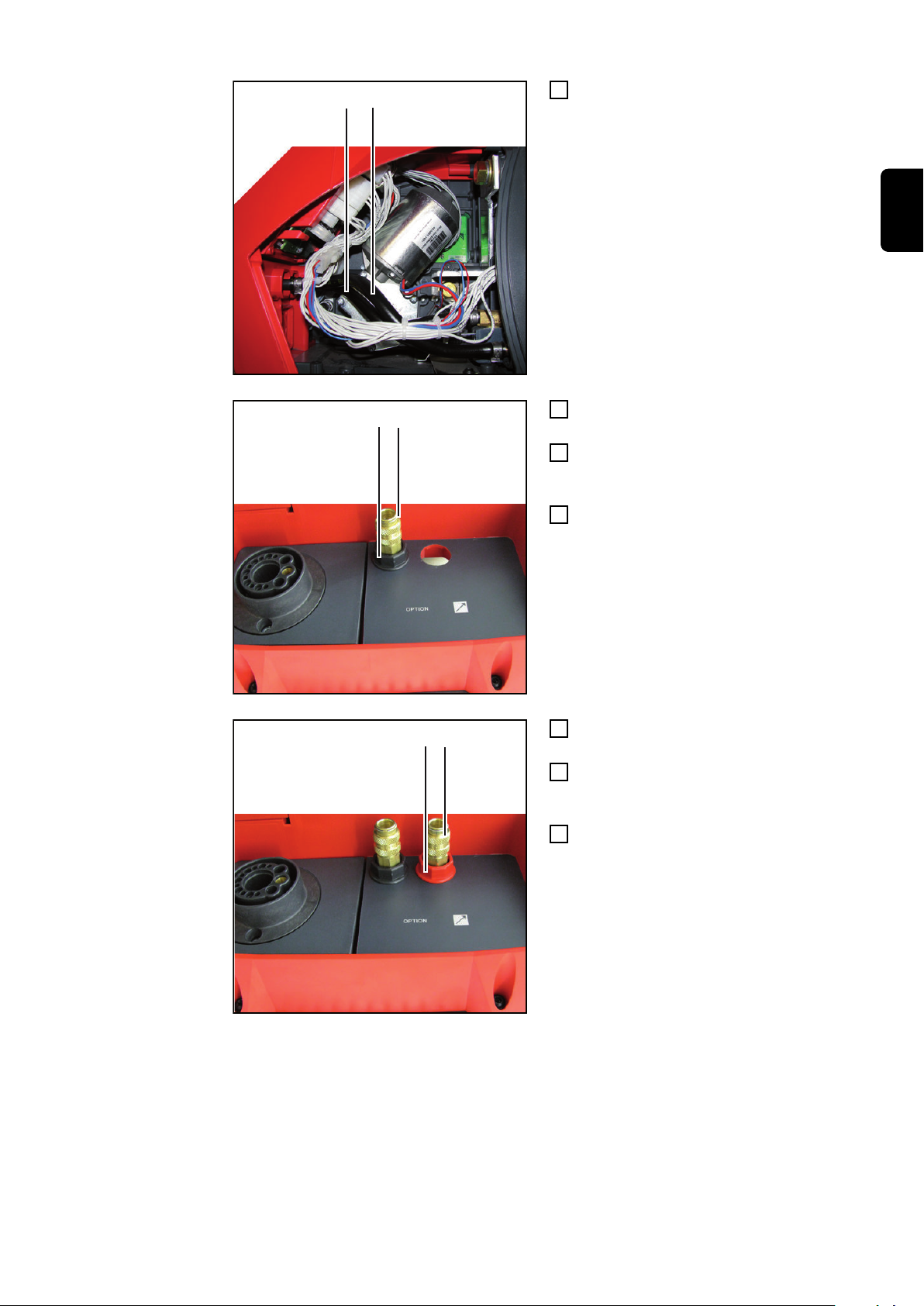
Wasserkühlung VR 5000 einbauen
(1)
(1)
(2) (2)
Vorbereitungen
Sämtliche Verbindungen des Drahtvorschubes von allen anderen Systemkomponen-
1
ten trennen
Draht- oder Korbspule dem Drahtvorschub entnehmen
2
Drahtvorschub auf einer geeigneten Unterlage auf der linken Seite ablegen (von
3
vorne gesehen)
2 Schrauben TX 25 (1) lösen
4
Seitenteil entfernen
5
Haken (2) an den Blindabdeckungen bei
den nachfolgenden Arbeitsschritten mit
einem kleinen Schraubendreher nach
innen drücken.
4
Page 5

(3)
(3)
Blindabdeckungen (3) an der Draht-
(4)(4)
(2)(1)
6
vorschub-Rückseite entfernen
Blindabdeckungen (4) an der Draht-
7
vorschub-Vorderseite entfernen
DE
Wasserkühlung
VR 5000 einbauen
Kunststoff-Mutter (1) von Kühlmittel-
1
Schraubanschluss Vorlauf (2)
abschrauben
Kühlmittel-Schraubanschluss Vorlauf
2
(2) durch Drahtvorschub-Rückseite
wie abgebildet durchstecken
Kühlmittel-Schraubanschluss Vorlauf
3
(2) mittels Kunststoffmutter (1) festschrauben
- Anzugsmoment = 3,5 Nm
5
Page 6

(4)(3)
Kunststoff-Mutter (3) von Kühlmittel-
(5)
(5)
(6)(7)
4
Schraubanschluss Rücklauf (4)
abschrauben
Kühlmittel-Schraubanschluss Rücklauf
5
(4) durch Drahtvorschub-Rückseite
wie abgebildet durchstecken
Kühlmittel-Schraubanschluss Rücklauf
6
(4) mittels Kunststoffmutter (3) festschrauben
- Anzugsmoment = 3,5 Nm
Kühlmittel-Schläuche (5) wie abgebil-
7
det verlegen
Kunststoff-Mutter (6) von Kühlmittel-
8
Steckanschluss Vorlauf (7) abschrauben
Kühlmittel-Steckanschluss Vorlauf (7)
9
durch Drahtvorschub-Vorderseite wie
abgebildet durchstecken
Kühlmittel-Steckanschluss Vorlauf (7)
10
mittels Kunststoff-Mutter (6) festschrauben
- Anzugsmoment = 3,5 Nm
6
Page 7

(8)(9)
Kunststoff-Mutter (8) von Kühlmittel-
(1)
(1)
11
Steckanschluss Rücklauf (9)
abschrauben
Kühlmittel-Steckanschluss Rücklauf
12
(9) durch Drahtvorschub-Vorderseite
wie abgebildet durchstecken
Kühlmittel-Steckanschluss Rücklauf
13
(9) mittels Kunststoff-Mutter (8) festschrauben
- Anzugsmoment = 3,5 Nm
DE
Abschließende
Tätigkeiten
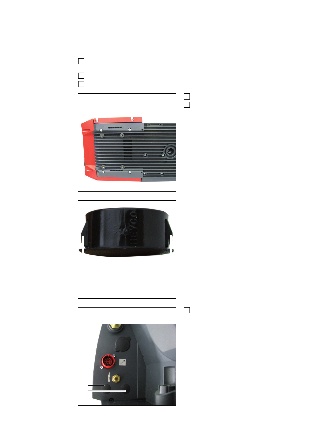
Seitenteil einsetzen
1
2 Schrauben 5 x 14 mm (1) mittels
2
Schraubendreher TX 25 festschrauben
- Anzugsmoment = 2,5 Nm
Drahtvorschub wieder in seine Aus-
3
gangsposition bringen
Draht- oder Korbspule einsetzen
4
Verbindungen mit anderen System-
5
komponenten wieder herstellen
7
Page 8

General
(1)
(2)
Safety
Scope of supply
WARNING!
Danger from electric current.
An electric shock can be fatal.
Before opening the device turn the power source mains switch to the "O" position
▶
Unplug the power source from the mains.
▶
Put up an easy-to-understand warning sign to stop anybody inadvertently switching
▶
it back on again.
WARNING!
Danger due to work that has been carried out incorrectly.
This can result in severe personal injury and damage to property.
The following activities must only be carried out by trained and qualified personnel.
▶
Read the "Safety rules" chapter in the power source and system components opera-
▶
ting instructions.
(1) Coolant return hose with 2 plastic
nuts
(2) Coolant flow hose with 2 plastic
nuts (marked with blue adhesive
tape)
Tools required - TX 25 Torx screwdriver
- 22 mm flat spanner
- Small slotted screwdriver
8
Page 9

Installing VR 5000 water cooling
(1)
(1)
(2) (2)
(3)
(3)
Preparations
Disconnect all connections on the wire-feed unit from all other system components
1
Take wire spool or basket spool off the wire-feed unit
2
Place wire-feed unit on its left-hand side on a suitable base (seen from the front)
3
Undo 2 x TX 25 screws (1)
4
Remove the side panel
5
In the following steps, push catches (2) on
the blanking covers inwards using a small
screwdriver.
EN
Remove the blanking covers (3) on
6
the rear of the wire-feed unit
9
Page 10

(4)(4)
Remove the blanking covers (4) on
(2)(1)
(4)(3)
7
the front of the wire-feed unit
Installing VR
5000 water cooling
Unscrew plastic nut (1) on the coolant
1
flow screw connection (2)
Insert the coolant flow screw connec-
2
tion (2) through the rear of the wirefeed unit as shown
Secure the coolant flow screw connec-
3
tion (2) using the plastic nut (1)
- Tightening torque = 3.5 Nm
Unscrew plastic nut (3) on the coolant
4
return screw connection (4)
Insert the coolant return screw con-
5
nection (4) through the rear of the
wire-feed unit as shown
Secure the coolant return screw con-
6
nection (4) using the plastic nut (3)
- Tightening torque = 3.5 Nm
10
Page 11
(5)
(5)
Route coolant hoses (5) as shown
(6)(7)
(8)(9)
7
Unscrew plastic nut (6) on the coolant
8
flow plug connection (7)
Insert the coolant flow plug connection
9
(7) through the front of the wire-feed
unit as shown
Secure the coolant flow plug connec-
10
tion (7) using the plastic nut (6)
- Tightening torque = 3.5 Nm
EN
Unscrew plastic nut (8) on the coolant
11
return plug connection (9)
Insert the coolant return plug connec-
12
tion (9) through the front of the wirefeed unit as shown
Secure the coolant return plug con-
13
nection (9) using the plastic nut (8)
- Tightening torque = 3.5 Nm
11
Page 12

Finally...
(1)
(1)
Insert side panel
1
Tighten two 5 x 14 mm screws (1)
2
using TX 25 screwdriver
- Tightening torque = 2.5 Nm
Return wire-feed unit to its original
3
position
Insert wire spool or basket spool
4
Restore connections to other system
5
components
12
Page 13

Généralités
(1)
(2)
Sécurité
Livraison
AVERTISSEMENT!
Risque d'électrocution.
Une décharge électrique peut être mortelle.
Avant d'ouvrir l'appareil placer l'interrupteur principal de la source de courant en
▶
position - O -.
Débrancher la prise secteur de la source de courant.
▶
Apposer un panneau d'avertissement compréhensible afin de prévenir toute remise
▶
en marche.
AVERTISSEMENT!
Danger en cas d'erreurs en cours d'opération.
Cela peut entraîner des dommages corporels et matériels graves.
Les opérations décrites ci-après doivent être effectuées exclusivement par du per-
▶
sonnel qualifié et formé !
Respecter les prescriptions du chapitre « Consignes de sécurité » figurant dans les
▶
Instructions de service de la source de courant et des composants du système.
(1) Flexible de réfrigérant Retour avec
2 écrous en plastique
(2) Flexible de réfrigérant Arrivée avec
2 écrous en plastique (repérés
avec de la bande collante bleue)
FR
Outillage nécessaire
- Tournevis Torx TX 25
- Clé à fourche SW 22 mm
- Tournevis plat, petit modèle
13
Page 14
Monter le refroidissement par eau VR 5000
(1)
(1)
(2) (2)
(3)
(3)
Préparations
Débrancher toutes les connexions du dévidoir vers les autres composants du
1
système.
Retirer la bobine de fil ou la bobine type panier du dévidoir
2
Coucher le dévidoir sur le côté gauche (vu de devant) sur un support adapté
3
Desserrer les 2 vis TX 25 (1)
4
Retirer le panneau latéral
5
Au cours des étapes de travail suivantes,
pousser vers l'intérieur les crochets (2)
des fausses prises à l'aide d'un petit tournevis.
14
Retirer les fausses prises (3) sur la
6
face arrière du dévidoir
Page 15

(4)(4)
Retirer les fausses prises (4) sur la
(2)(1)
(4)(3)
7
face avant du dévidoir
FR
Monter le refroidissement par
eau VR 5000
Dévisser l'écrou en plastique (1) du
1
raccord à vis de flexible de réfrigérant
Arrivée (2)
Passer le raccord à vis de flexible de
2
réfrigérant Arrivée (2) à travers la face
arrière du dévidoir, comme indiqué sur
l'illustration
Revisser le raccord à vis de flexible de
3
réfrigérant Arrivée (2) avec l'écrou en
plastique (1)
- Couple de serrage = 3,5 Nm
Dévisser l'écrou en plastique (3) du
4
raccord à vis de flexible de réfrigérant
Retour (4)
Passer le raccord à vis de flexible de
5
réfrigérant Retour (4) à travers la face
arrière du dévidoir, comme indiqué sur
l'illustration
Revisser le raccord à vis de flexible de
6
réfrigérant Retour (4) avec l'écrou en
plastique (3)
- Couple de serrage = 3,5 Nm
15
Page 16

(5)
(5)
Poser les flexibles de réfrigérant (5)
(6)(7)
(8)(9)
7
comme indiqué sur l'illustration
Dévisser l'écrou en plastique (6) du
8
raccord enfichable de flexible de
réfrigérant Arrivée (7)
Passer le raccord enfichable de flexi-
9
ble de réfrigérant Arrivée (7) à travers
la face avant du dévidoir, comme
indiqué sur l'illustration
Revisser le raccord enfichable de fle-
10
xible de réfrigérant Arrivée (7) avec
l'écrou en plastique (6)
- Couple de serrage = 3,5 Nm
Dévisser l'écrou en plastique (8) du
11
raccord enfichable de flexible de
réfrigérant Retour (9)
Passer le raccord enfichable de flexi-
12
ble de réfrigérant Retour (9) à travers
la face avant du dévidoir, comme
indiqué sur l'illustration
Revisser le raccord enfichable de fle-
13
xible de réfrigérant Retour (9) avec
l'écrou en plastique (8)
- Couple de serrage = 3,5 Nm
16
Page 17

Étapes finales
(1)
(1)
Mettre en place la partie latérale
1
Visser les 2 vis 5 x 14 mm (1) à l'aide
2
du tournevis TX 25
- Couple de serrage = 2,5 Nm
Replacer le dévidoir dans sa position
3
initiale
Mettre en place la bobine de fil ou la
4
bobine type panier du dévidoir
Rétablir la connexion avec les autres
5
composants du système
FR
17
Page 18

18
Page 19

FR
19
Page 20

FRONIUS INTERNATIONAL GMBH
Froniusstraße 1
A-4643 Pettenbach
AUSTRIA
contact@fronius.com
www.fronius.com
Under www.fronius.com/contact you will find the addresses
of all Fronius Sales & Service Partners and locations
 Loading...