

Page 1

/ Battery Charging Systems / Welding Technology / Solar Electronics
DE
EN
FR
Anschluss Fernbedienung VR 5000
VR 5000 remote control connection
Raccord de télécommande VR 5000
Einbauanleitung
Systemerweiterung
Installation instructions
System extension
Instructions d'installation
Extension système
42,0410,1736 002-04042012
Page 2

0
Page 3

Inhaltsverzeichnis
Allgemeines ............................................................................................................................................... 3
Sicherheit.............................................................................................................................................. 3
Lieferumfang......................................................................................................................................... 3
Benötigtes Werkzeug........................................................................................................................... 3
Anschluss Fernbedienung VR 5000 einbauen........................................................................................... 4
Vorbereitungen ..................................................................................................................................... 4
Anschluss Fernbedienung VR 5000 einbauen...................................................................................... 4
Abschließende Tätigkeiten.................................................................................................................... 6
DE
1
Page 4

2
Page 5

Allgemeines
DE
Sicherheit
Lieferumfang
(1)
WARNUNG! Ein elektrischer Schlag kann tödlich sein. Vor Öffnen des Gerätes
- Netzschalter in Stellung - O - schalten
- Gerät vom Netz trennen
- ein verständliches Warnschild gegen Wiedereinschalten anbringen
- mit Hilfe eines geeigneten Messgerätes sicherstellen, dass elektrisch geladene Bauteile (z.B. Kondensatoren) entladen sind
WARNUNG! Fehlerhaft durchgeführte Arbeiten können schwerwiegende Personen- und Sachschäden verursachen. Nachfolgend beschriebene Tätigkeiten
dürfen nur von geschultem Fachpersonal durchgeführt werden! Beachten Sie das
Kapitel „Sicherheitsvorschriften“ in der Bedienungsanleitung der Stromquelle und
der Systemkomponenten.
(1) Anschluss Fernbedienung VR 5000
(2)
(3)
(2) Abdeckung Anschluss Fernbedie-
nung VR 5000
(3) 2 Schrauben 4 x 8 mm
Benötigtes Werkzeug
- Torx-Schraubendreher TX 25
- Torx-Schraubendreher TX 20
- Messer
3
Page 6

Anschluss Fernbedienung VR 5000 einbauen
1
5
Vorbereitungen Sämtliche Verbindungen des Drahtvorschubes von allen anderen Systemkomponen-
ten trennen
Draht- oder Korbspule dem Drahtvorschub entnehmen
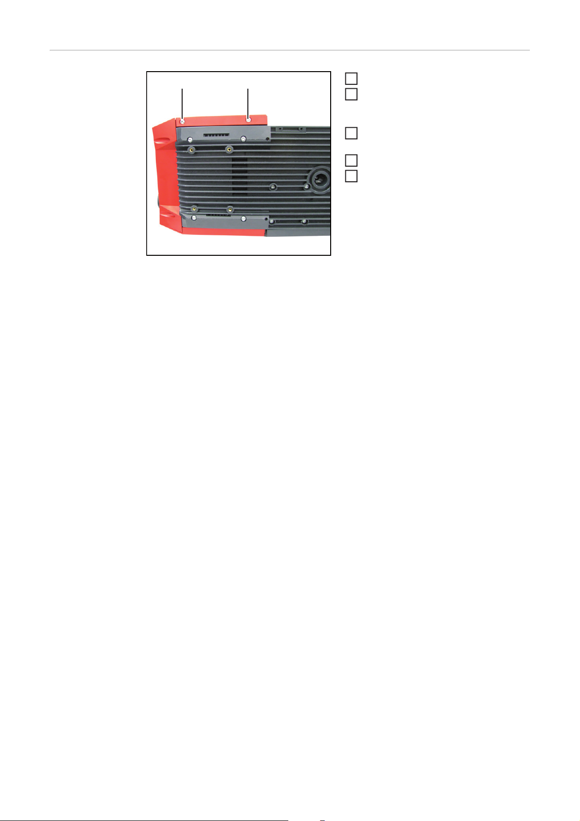
2
Drahtvorschub auf einer geeigneten Unterlage ablegen
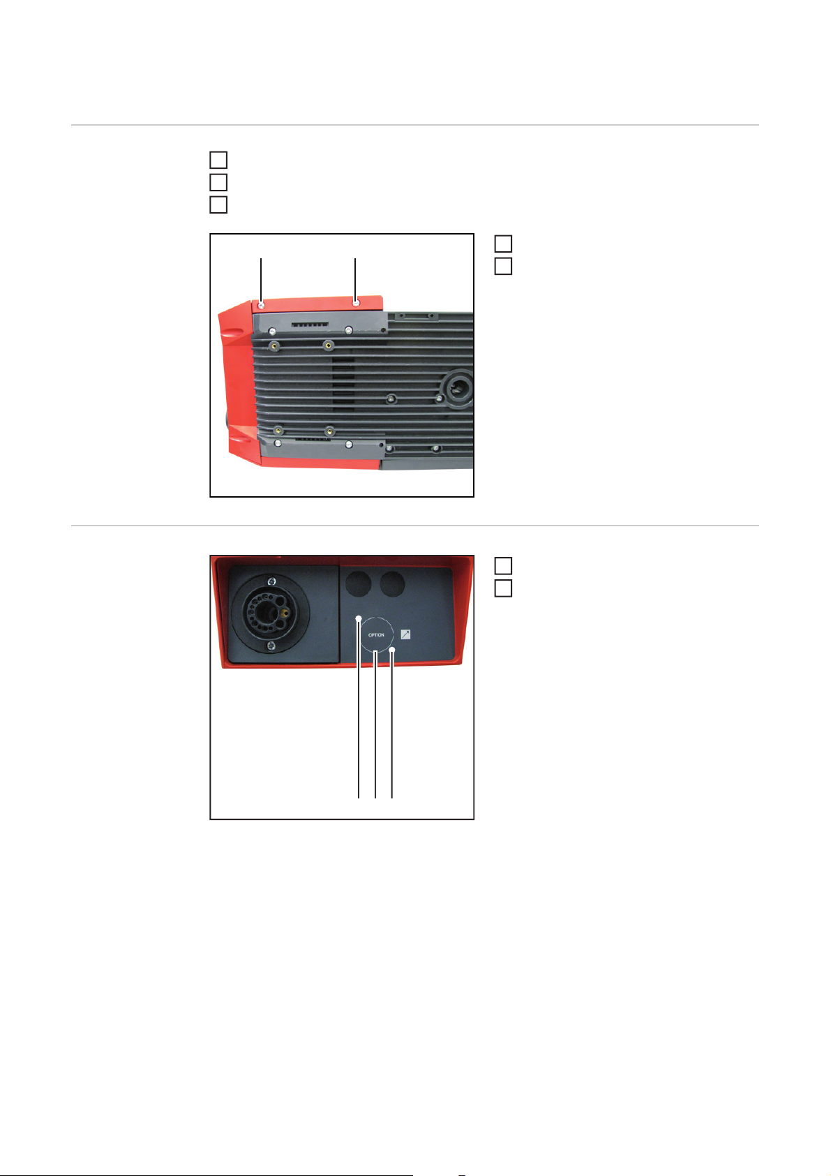
3
2 Schrauben TX 25 (1) lösen
(1)
(1)
4
Seitenteil rechts entfernen
Anschluss Fernbedienung VR
5000 einbauen
(1)(2) (3)
Folie entlang der Markierung (1) aus-
1
schneiden
An Position (2) und (3) Löcher in die
2
Frontfolie schneiden
- Durchmesser = 3 mm
4
Page 7

(4)
Kunststoff-Platzhalter (4) entfernen
3
Anschluss Fernbedienung VR 5000 (5)
4
von hinten durch den Drahtvorschub
stecken
Anschluss Fernbedienung VR 5000 (5)
5
mittels 2 Schrauben (6) festschrauben
- Anzugsmoment = 0,6 Nm
Abdeckung Anschluss Fernbedienung
6
VR 5000 auf Anschluss Fernbedienung VR 5000 (5) aufstecken
DE
(7)
(5)(6)(6)
Stecker des Anschlusses Fernbedie-
7
nung VR 5000 an Anschluss X9 (7)
des Print SRVT im Drahtvorschub anstecken
5
Page 8

Abschließende
(1)
(1)
2
4
Tätigkeiten
Seitenteil einsetzen
1
2 Schrauben 5 x 14 mm (1) mittels
Schraubendreher TX 25 festschrauben
- Anzugsmoment = 2,5 Nm
Drahtvorschub wieder in seine Aus-
3
gangsposition bringen
Draht- oder Korbspule einsetzen
Verbindungen mit anderen System-
5
komponenten wieder herstellen
6
Page 9

Contents
General ...................................................................................................................................................... 9
Safety.................................................................................................................................................... 9
Scope of supply .................................................................................................................................... 9
Tools required....................................................................................................................................... 9
Installing the VR 5000 remote control connection ..................................................................................... 10
Preparations.......................................................................................................................................... 10
Installing the VR 5000 remote control connection ................................................................................10
Finally.................................................................................................................................................... 12
EN
7
Page 10

8
Page 11

General
Safety
Scope of supply
(1)
WARNING! An electric shock can be fatal. Before opening the device
- Turn the mains switch to the "O" position
- Unplug the machine from the mains
- Put up an easy-to-understand warning sign to stop anybody inadvertently
switching it back on again
- Using a suitable measuring instrument, check to make sure that electrically
charged components (e.g. capacitors) have discharged
WARNING! Work that is carried out incorrectly can cause serious injury and damage. The following activities must only be carried out by trained and qualified personnel. Read the "Safety rules" chapter in the power source and system
components operating instructions.
(1) VR 5000 remote control connection
(2)
(3)
(2) Cover for VR 5000 remote control
connection
(3) Two 4 x 8 mm screws
EN
Tools required - TX 25 Torx screwdriver
- TX 20 Torx screwdriver
-Knife
9
Page 12
Installing the VR 5000 remote control connection
1
5
Preparations Disconnect all connections on the wire-feed unit from all other system components
Take wirespool or basket-type spool off the wire-feed unit
2
Place wire-feed unit on a suitable base
3
Undo two TX 25 screws (1)
(1)
(1)
4
Remove right side panel
Installing the VR
5000 remote control connection
(1)(2) (3)
Cut out film along marking (1)
1
Cut holes in the front of the film at po-
2
sitions (2) and (3)
- Diameter = 3 mm
10
Page 13

(4)
Remove plastic placeholders (4)
3
Insert the VR 5000 remote control con-
4
nection (5) from the rear through the
wire-feed unit
Tighten the VR 5000 remote control
5
connection (5) using two screws (6)
- Tightening torque = 0.6 Nm
Fit the cover for the VR 5000 remote
6
control connection on to the VR 5000
remote control connection (5)
EN
(7)
(5)(6)(6)
Connect the plug of the VR 5000 remo-
7
te control connection to the X9 connection (7) of the SRVT PC board in the
wire-feed unit
11
Page 14
Finally...
(1)
(1)
2
4
Insert side panel
1
Tighten two 5 x 14 mm screws (1)
using TX 25 screwdriver
- Tightening torque = 2.5 Nm
Return wire-feed unit to its original po-
3
sition
Insert wire spool or basket spool
Restore connections to other system
5
components
12
Page 15

Sommaire
Généralités................................................................................................................................................. 15
Sécurité................................................................................................................................................. 15
Livraison................................................................................................................................................ 15
Outillage nécessaire ............................................................................................................................. 15
Monter le raccord de télécommande VR 5000 .......................................................................................... 16
Préparations.......................................................................................................................................... 16
Monter le raccord de télécommande VR 5000 ..................................................................................... 16
Étapes finales ....................................................................................................................................... 18
FR
13
Page 16

14
Page 17

Généralités
Sécurité
Livraison
(1)
AVERTISSEMENT ! Un choc électrique peut être mortel. Avant d'ouvrir l'appareil
- commuter l’interrupteur du secteur en position - O -
- débrancher l'appareil du secteur
- apposer un panneau d'avertissement compréhensible afin de prévenir toute
remise en marche
- s'assurer, à l'aide d'un appareil de mesure approprié, que les composants à
charge électrique (condensateurs par ex.) sont déchargés
AVERTISSEMENT ! Les erreurs en cours d'opération peuvent entraîner des
dommages corporels et matériels graves. Les opérations décrites ci-après doivent être effectuées exclusivement par du personnel qualifié et formé ! Respecter
les prescriptions du chapitre « Consignes de sécurité » figurant dans les Instructions de service de la source de courant et des composants du système.
(1) Raccord de télécommande VR
(2)
(2) Cache pour raccord de télécom-
(3) 2 vis 4 x 8 mm
(3)
5000
mande VR 5000
FR
Outillage nécessaire
- Tournevis Torx TX 25
- Tournevis Torx TX 20
-Cutter
15
Page 18

Monter le raccord de télécommande VR 5000
1
5
Préparations Débrancher toutes les connexions du dévidoir vers les autres composants du système
Retirer la bobine de fil ou la bobine type panier du dévidoir
2
Placer le dévidoir sur un support adapté
3
Desserrer les 2 vis TX 25 (1)
(1)
(1)
4
Retirer la partie latérale droite
Monter le raccord
de télécommande
VR 5000
(1)(2) (3)
Découper le film le long du marquage
1
(1)
Découper des trous dans le film aux
2
positions (2) et (3)
- Diamètre = 3 mm
16
Page 19

(4)
Retirer le marque-place en plastique
3
(4)
Enficher le raccord de télécommande
4
VR 5000 (5) par l'arrière dans le dévidoir
Visser et serrer le raccord de télécom-
5
mande VR 5000 (5) avec les 2 vis (6)
- Couple de serrage = 0,6 Nm
Enficher le cache de raccord de télé-
6
commande VR 5000 sur le raccord de
télécommande VR 5000 (5)
FR
(7)
(5)(6)(6)
Brancher la prise du raccord de télé-
7
commande VR 5000 au connecteur X9
(7) du circuit imprimé SRVT dans le
dévidoir
17
Page 20

Étapes finales
(1)
(1)
2
4
Mettre en place la partie latérale
1
Visser les 2 vis 5 x 14 mm (1) à l'aide
du tournevis TX 25
- Couple de serrage = 2,5 Nm
Replacer le dévidoir dans sa position
3
initiale
Mettre en place la bobine de fil ou la
bobine type panier du dévidoir
Rétablir la connexion avec les autres
5
composants du système
18
Page 21

FR
19
Page 22

FRONIUS INTERNATIONAL GMBH
Froniusplatz 1, A-4600 Wels, Austria
Tel: +43 (0)7242 241-0, Fax: +43 (0)7242 241-3940
Under http://www.fronius.com/addresses you will find all addresses
of our Sales & service partners and Locations
E-Mail: sales@fronius.com
www.fronius.com
www.fronius.com/addresses
 Loading...