

Page 1

/ Perfect Charging / Perfect Welding / Solar Energy
42,0426,0080,EN 027-21122018
VR 5000, VR 5000 noSpool
Operating Instructions
Spare parts list
Wire-feed unit
EN
Page 2

2
Page 3

3
EN
Dear reader,
Introduction Thank you for the trust you have placed in our company and congratulations on buying this
high-quality Fronius product. These instructions will help you familiarise yourself with the
product. Reading the instructions carefully will enable you to learn about the many different
features it has to offer. This will allow you to make full use of its advantages.
Please also note the safety rules to ensure greater safety when using the product. Careful
handling of the product will repay you with years of safe and reliable operation. These are
essential prerequisites for excellent results.
Explanation of
safety notices
DANGER!
Indicates immediate danger.
► If not avoided, death or serious injury will result.
WARNING!
Indicates a potentially hazardous situation.
► If not avoided, death or serious injury may result.
CAUTION!
Indicates a situation where damage or injury could occur.
► If not avoided, minor injury and/or damage to property may result.
NOTE!
Indicates a risk of flawed results and possible damage to the equipment.
IMPORTANT!
Indicates tips for correct operation and other particularly useful information.
This does not indicate a potentially hazardous situation.
If you see any of the symbols depicted in the "Safety rules" chapter, special care is required.
Page 4

4
Page 5

5
EN
Contents
Safety rules ................................................................................................................................................ 9
General ................................................................................................................................................. 9
Proper use ............................................................................................................................................ 9
Environmental conditions...................................................................................................................... 9
Obligations of the operator.................................................................................................................... 10
Obligations of personnel ....................................................................................................................... 10
Mains connection .................................................................................................................................. 10
Protecting yourself and others .............................................................................................................. 10
Danger from toxic gases and vapours .................................................................................................. 11
Danger from flying sparks ..................................................................................................................... 11
Risks from mains current and welding current...................................................................................... 12
Meandering welding currents................................................................................................................ 13
EMC Device Classifications .................................................................................................................. 13
EMC measures ..................................................................................................................................... 13
EMF measures...................................................................................................................................... 14
Specific hazards.................................................................................................................................... 14
Factors affecting welding results........................................................................................................... 15
Danger from shielding gas cylinders..................................................................................................... 15
Danger from escaping shielding gas..................................................................................................... 16
Safety measures at the installation location and during transport ........................................................ 16
Safety measures in normal operation ................................................................................................... 17
Commissioning, maintenance and repair.............................................................................................. 17
Safety inspection................................................................................................................................... 17
Disposal ................................................................................................................................................ 18
Safety symbols...................................................................................................................................... 18
Data protection...................................................................................................................................... 18
Copyright............................................................................................................................................... 18
General information 19
General ...................................................................................................................................................... 21
Device concept ..................................................................................................................................... 21
Requirements........................................................................................................................................ 21
Application area .................................................................................................................................... 21
Warning notices on the device.............................................................................................................. 21
Description of Warning Notices on the Device...................................................................................... 23
Control elements and connections 25
Description of the control panels................................................................................................................ 27
General information .............................................................................................................................. 27
Safety.................................................................................................................................................... 27
Manual control panel.................................................................................................................................. 28
General ................................................................................................................................................ 28
Manual control panel............................................................................................................................. 28
Adjustment aid for Manual control panel............................................................................................... 29
Keylock ................................................................................................................................................. 30
Service parameters............................................................................................................................... 30
Synergic control panel ............................................................................................................................... 32
General ................................................................................................................................................. 32
Control panel splitting ........................................................................................................................... 32
Synergic A control panel ....................................................................................................................... 32
Synergic B control panel overview........................................................................................................ 34
Synergic B control panel ....................................................................................................................... 35
Keylock ................................................................................................................................................. 36
Service parameters............................................................................................................................... 36
Connections and mechanical components ................................................................................................ 38
Overview of connections for the welding torch ..................................................................................... 38
Front of wire-feed unit ........................................................................................................................... 38
Rear of wirefeeder ................................................................................................................................ 38
Page 6

6
Wire-feed unit side ................................................................................................................................ 39
Wire-feed unit underside....................................................................................................................... 40
Installation and commissioning 41
Before commissioning................................................................................................................................ 43
Safety.................................................................................................................................................... 43
Intended purpose .................................................................................................................................. 43
Setup regulations .................................................................................................................................. 43
Placing wire-feed unit on power source ..................................................................................................... 45
General information .............................................................................................................................. 45
Placing wire-feed unit on power source ................................................................................................ 45
Connecting wire-feed unit to power source................................................................................................ 46
General information .............................................................................................................................. 46
Connecting wire-feed unit to power source........................................................................................... 46
Connecting the welding torch..................................................................................................................... 47
Safety.................................................................................................................................................... 47
Connecting MIG/MAG manual welding torches .................................................................................... 47
Inserting/replacing feed rollers................................................................................................................... 48
General ................................................................................................................................................. 48
Inserting/replacing feed rollers.............................................................................................................. 48
Inserting the wirespool, inserting the basket-type spool ............................................................................ 49
Safety.................................................................................................................................................... 49
Inserting the wirespool .......................................................................................................................... 49
Inserting the basket-type spool ............................................................................................................. 50
Feeding in the wire electrode..................................................................................................................... 52
Feeding in the wire electrode................................................................................................................ 52
Setting the contact pressure ................................................................................................................. 53
Adjust the brake ......................................................................................................................................... 55
General ................................................................................................................................................. 55
Adjusting the brake ............................................................................................................................... 55
Design of the brake............................................................................................................................... 56
Start-up ...................................................................................................................................................... 57
General information .............................................................................................................................. 57
Requirements........................................................................................................................................ 57
Welding 59
Power limitation.......................................................................................................................................... 61
Safety function ...................................................................................................................................... 61
MIG/MAG modes ....................................................................................................................................... 62
General ................................................................................................................................................. 62
Symbols and their explanations ............................................................................................................ 62
2-step mode .......................................................................................................................................... 63
4-step mode .......................................................................................................................................... 63
Special 4-step mode ............................................................................................................................. 63
Spot welding ......................................................................................................................................... 63
2-step stitch welding ............................................................................................................................. 64
4-step stitch welding ............................................................................................................................. 64
MIG/MAG welding...................................................................................................................................... 65
Safety.................................................................................................................................................... 65
General tasks before MIG/MAG welding .............................................................................................. 65
Overview ............................................................................................................................................... 65
MIG/MAG standard synergic welding ........................................................................................................ 66
General ................................................................................................................................................. 66
MIG/MAG standard synergic welding ................................................................................................... 66
Corrections during welding ................................................................................................................... 67
MIG/MAG standard manual welding .......................................................................................................... 68
General ................................................................................................................................................. 68
Available parameters ............................................................................................................................ 68
MIG/MAG standard manual welding - manual control panel ................................................................ 68
Adjustments while welding - manual control panel ...............................................................................69
MIG/MAG standard manual welding - Synergic A control panel........................................................... 69
Adjustments while welding - Synergic A control panel.......................................................................... 71
Page 7

7
EN
MMA welding ............................................................................................................................................. 72
Safety.................................................................................................................................................... 72
Preparations.......................................................................................................................................... 72
MMA welding - manual control panel.................................................................................................... 72
Adjustments while welding - manual control panel ...............................................................................73
MMA welding - Synergic A control panel .............................................................................................. 73
Corrections during welding ................................................................................................................... 74
HotStart function ................................................................................................................................... 74
Anti-stick function.................................................................................................................................. 74
Saving and retrieving operating points....................................................................................................... 75
General ................................................................................................................................................. 75
Saving operating points ........................................................................................................................ 75
Retrieving operating points ................................................................................................................... 75
Deleting operating points ...................................................................................................................... 75
Retrieving operating points on the Up/Down welding torch .................................................................. 75
Setup settings 77
Setup menu................................................................................................................................................ 79
General remarks ................................................................................................................................... 79
Setup menu - manual control panel ...................................................................................................... 79
Setup menu - Synergic A control panel ................................................................................................ 79
Setup parameters for MIG/MAG standard manual welding .................................................................. 81
Setup parameters for MIG/MAG standard synergic welding................................................................. 83
Setup parameters for MMA welding...................................................................................................... 84
Welding parameters for "Special 4-step mode" in the Mode setup menu............................................. 85
Setup menu - Level 2................................................................................................................................. 86
Level 2 setup menu - manual control panel .......................................................................................... 86
Level 2 setup menu - Synergic control panel........................................................................................ 86
Welding parameters for MIG/MAG welding in the Setup menu level 2................................................. 88
Parameters for manual metal arc (MMA) welding in the Setup menu level 2 ....................................... 89
Measuring welding circuit resistance r ....................................................................................................... 90
General ................................................................................................................................................. 90
Measure the welding circuit resistance r............................................................................................... 90
Displaying welding circuit inductivity L ....................................................................................................... 91
General ................................................................................................................................................. 91
Displaying welding circuit inductivity L .................................................................................................. 91
Laying the hosepacks correctly............................................................................................................. 91
Troubleshooting and maintenance 93
Troubleshooting ......................................................................................................................................... 95
General ................................................................................................................................................. 95
Safety.................................................................................................................................................... 95
Fault diagnosis...................................................................................................................................... 95
Displayed service codes ....................................................................................................................... 98
Care, maintenance and disposal ............................................................................................................... 104
General ................................................................................................................................................. 104
Safety.................................................................................................................................................... 104
Every start-up........................................................................................................................................ 104
Every 6 months ..................................................................................................................................... 104
Disposal ................................................................................................................................................ 104
Technical data and settings tables 105
Technical data............................................................................................................................................ 107
VR 5000 ................................................................................................................................................ 107
VR 5000 noSpool.................................................................................................................................. 107
Manual control panel settings tables.......................................................................................................... 109
Settings tables ...................................................................................................................................... 109
Welding program tables ............................................................................................................................. 115
TransSteel 3500 Euro welding program tables .................................................................................... 115
TransSteel 5000 Euro welding program tables .................................................................................... 116
TransSteel 3500 US welding program tables ...................................................................................... 117
Page 8

8
TransSteel 5000 US welding program tables ...................................................................................... 118
TransSteel 3500 Yard welding program tables .................................................................................... 119
TransSteel 5000 Yard welding program tables .................................................................................... 120
Quick reference.......................................................................................................................................... 121
Appendix 123
Spare parts list: VR 5000 ........................................................................................................................... 124
Page 9

9
EN
Safety rules
General The device is manufactured using state-of-the-art technology and according to recognised
safety standards. If used incorrectly or misused, however, it can cause:
- injury or death to the operator or a third party,
- damage to the device and other material assets belonging to the operating company,
- inefficient operation of the device.
All persons involved in commissioning, operating, maintaining and servicing the device
must:
- be suitably qualified,
- have sufficient knowledge of welding and
- read and follow these operating instructions carefully.
The operating instructions must always be at hand wherever the device is being used. In
addition to the operating instructions, attention must also be paid to any generally applicable and local regulations regarding accident prevention and environmental protection.
All safety and danger notices on the device
- must be in a legible state,
- must not be damaged,
- must not be removed,
- must not be covered, pasted or painted over.
For the location of the safety and danger notices on the device, refer to the section headed
"General" in the operating instructions for the device.
Before switching on the device, rectify any faults that could compromise safety.
This is for your personal safety!
Proper use The device is to be used exclusively for its intended purpose.
The device is intended solely for the welding processes specified on the rating plate.
Any use above and beyond this purpose is deemed improper. The manufacturer shall not
be held liable for any damage arising from such usage.
Proper use includes:
- carefully reading and following all the instructions given in the operating instructions
- studying and obeying all safety and danger notices carefully
- performing all stipulated inspection and maintenance work.
Never use the device for the following purposes:
- Thawing out pipes
- Charging batteries
- Starting engines
The device is designed for use in industry and the workshop. The manufacturer accepts
no responsibility for any damage caused through use in a domestic setting.
The manufacturer likewise accepts no liability for inadequate or incorrect results.
Environmental
conditions
Operation or storage of the device outside the stipulated area will be deemed as not in accordance with the intended purpose. The manufacturer shall not be held liable for any damage arising from such usage.
Page 10

10
Ambient temperature range:
- during operation: -10 °C to + 40 °C (14 °F to 104 °F)
- during transport and storage: -20 °C to +55 °C (-4 °F to 131 °F)
Relative humidity:
- up to 50% at 40 °C (104 °F)
- up to 90% at 20 °C (68 °F)
The surrounding air must be free from dust, acids, corrosive gases or substances, etc.
Can be used at altitudes of up to 2000 m (6561 ft. 8.16 in.)
Obligations of the
operator
The operator must only allow persons to work with the device who:
- are familiar with the fundamental instructions regarding safety at work and accident
prevention and have been instructed in how to use the device
- have read and understood these operating instructions, especially the section "safety
rules", and have confirmed as much with their signatures
- are trained to produce the required results.
Checks must be carried out at regular intervals to ensure that operators are working in a
safety-conscious manner.
Obligations of
personnel
Before using the device, all persons instructed to do so undertake:
- to observe the basic instructions regarding safety at work and accident prevention
- to read these operating instructions, especially the "Safety rules" section and sign to
confirm that they have understood them and will follow them.
Before leaving the workplace, ensure that people or property cannot come to any harm in
your absence.
Mains connection Devices with a higher rating may affect the energy quality of the mains due to their current
consumption.
This may affect a number of types of device in terms of:
- connection restrictions
- criteria with regard to the maximum permissible mains impedance
*)
- criteria with regard to the minimum short-circuit power requirement
*)
*)
at the interface with the public grid
see Technical Data
In this case, the plant operator or the person using the device should check whether the
device may be connected, where appropriate by discussing the matter with the power supply company.
IMPORTANT! Ensure that the mains connection is earthed properly
Protecting yourself and others
Anyone working with the device exposes themselves to numerous risks, e.g.
- flying sparks and hot pieces of metal
- Arc radiation, which can damage eyes and skin
- Hazardous electromagnetic fields, which can endanger the lives of those using cardiac pacemakers
- Risk of electrocution from mains current and welding current
- Greater noise pollution
- Harmful welding fumes and gases
Page 11

11
EN
Suitable protective clothing must be worn when working with the device. The protective
clothing must have the following properties:
- Flame-resistant
- Insulating and dry
- Covers the whole body, is undamaged and in good condition
- Safety helmet
- Trousers with no turn-ups
Protective clothing refers to a variety of different items. Operators should:
- Protect eyes and face from UV rays, heat and sparks using a protective visor and regulation filter
- Wear regulation protective goggles with side protection behind the protective visor
- Wear stout footwear that provides insulation even in wet conditions
- Protect the hands with suitable gloves (electrically insulated and providing protection
against heat)
- Wear ear protection to reduce the harmful effects of noise and to prevent injury
Keep all persons, especially children, out of the working area while any devices are in operation or welding is in progress. If, however, there are people in the vicinity:
- Make them aware of all the dangers (risk of dazzling by the arc, injury from flying
sparks, harmful welding fumes, noise, possible risks from mains current and welding
current, etc.)
- Provide suitable protective equipment
- Alternatively, erect suitable safety screens/curtains.
Danger from toxic
gases and vapours
The fumes produced during welding contain harmful gases and vapours.
Welding fumes contain substances that may, under certain circumstances, cause birth defects or cancer.
Keep your face away from welding fumes and gases.
Fumes and hazardous gases
- must not be breathed in
- must be extracted from the working area using appropriate methods.
Ensure an adequate supply of fresh air with a ventilation rate of at least 20 m³/hour.
Otherwise, a protective mask with an air supply must be worn.
Close the shielding gas cylinder valve or main gas supply if no welding is taking place.
If there is any doubt about whether the extraction capacity is sufficient, the measured toxic
emission values should be compared with the permissible limit values.
Amongst others, the following components are responsible for the degree of toxicity of
welding fumes:
- Metals used for the workpiece
- Electrodes
- Coatings
- Cleaners, degreasers, etc.
The relevant material safety data sheets and manufacturer's specifications for the listed
components should therefore be studied carefully.
Flammable vapours (e.g. solvent fumes) should be kept away from the arc's radiation area.
Danger from flying sparks
Flying sparks may cause fires or explosions.
Never weld close to flammable materials.
Page 12

12
Flammable materials must be at least 11 metres (36 ft. 1.07 in.) away from the arc, or alternatively covered with an approved cover.
A suitable, tested fire extinguisher must be available and ready for use.
Sparks and pieces of hot metal may also get into adjacent areas through small gaps or
openings. Take appropriate precautions to prevent any danger of injury or fire.
Welding must not be performed in areas that are subject to fire or explosion or near sealed
tanks, vessels or pipes unless these have been prepared in accordance with the relevant
national and international standards.
Do not carry out welding on containers that are being or have been used to store gases,
propellants, mineral oils or similar products. Residues pose an explosive hazard.
Risks from mains
current and welding current
An electric shock is potentially life threatening and can be fatal.
Do not touch live parts either inside or outside the device.
During MIG/MAG welding and TIG welding, the welding wire, the wirespool, the feed rollers
and all pieces of metal that are in contact with the welding wire are live.
Always set the wirefeeder up on a sufficiently insulated surface or use a suitable, insulated
wirefeeder holder.
Make sure that you and others are protected with an adequately insulated, dry temporary
backing or cover for the earth or ground potential. This temporary backing or cover must
extend over the entire area between the body and the earth or ground potential.
All cables and leads must be secured, undamaged, insulated and adequately dimensioned. Replace loose connections and scorched, damaged or inadequately dimensioned
cables and leads immediately.
Use the handle to ensure the power connections are tight before every use.
In the case of power cables with a bayonet connector, rotate the power cable around the
longitudinal axis by at least 180° and pre-load.
Do not wrap cables or leads around the body or parts of the body.
The electrode (rod electrode, tungsten electrode, welding wire, etc.) must
- never be immersed in liquid for cooling
- Never touch the electrode when the power source is switched on.
Double the open circuit voltage of a power source can occur between the welding electrodes of two power sources. Touching the potentials of both electrodes at the same time
may be fatal under certain circumstances.
Arrange for the mains cable to be checked regularly by a qualified electrician to ensure the
ground conductor is functioning properly.
The device must only be operated on a mains supply with a ground conductor and a socket
with a ground conductor contact.
Operating the device on a grid without a ground conductor and in a socket without a ground
conductor contact will be deemed gross negligence. The manufacturer shall not be held
liable for any damage arising from such usage.
If necessary, provide an adequate earth connection for the workpiece.
Switch off unused devices.
Wear a safety harness if working at height.
Before working on the device, switch it off and pull out the mains plug.
Page 13

13
EN
Attach a clearly legible and easy-to-understand warning sign to the device to prevent anyone from plugging the mains plug back in and switching it on again.
After opening the device:
- Discharge all live components
- Ensure that all components in the device are de-energised
If work on live parts is required, appoint a second person to switch off the main switch at
the right moment.
Meandering welding currents
If the following instructions are ignored, meandering welding currents can develop with the
following consequences:
- Fire hazard
- Overheating of parts connected to the workpiece
- Irreparable damage to ground conductors
- Damage to device and other electrical equipment
Ensure that the workpiece is held securely by the workpiece clamp.
Attach the workpiece clamp as close as possible to the area that is to be welded.
If the floor is electrically conductive, the device must be set up with sufficient insulating material to insulate it from the floor.
If distribution boards, twin-head mounts, etc., are being used, note the following: The electrode of the welding torch / electrode holder that is not used is also live. Make sure that the
welding torch / electrode holder that is not used is kept sufficiently insulated.
In the case of automated MIG/MAG applications, ensure that only an insulated wire electrode is routed from the welding wire drum, large wirefeeder spool or wirespool to the wirefeed unit.
EMC Device Classifications
Devices in emission class A:
- Are only designed for use in industrial settings
- Can cause line-bound and radiated interference in other areas
Devices in emission class B:
- Satisfy the emissions criteria for residential and industrial areas. This is also true for
residential areas in which the energy is supplied from the public low-voltage mains.
EMC device classification as per the rating plate or technical data.
EMC measures In certain cases, even though a device complies with the standard limit values for emis-
sions, it may affect the application area for which it was designed (e.g. when there is sensitive equipment at the same location, or if the site where the device is installed is close to
either radio or television receivers).
If this is the case, then the operator is obliged to take appropriate action to rectify the situation.
Check and evaluate the immunity to interference of nearby devices according to national
and international regulations. Examples of equipment that may be susceptible to interference from the device include:
- Safety devices
- Power, signal and data transfer lines
- IT and telecommunications devices
- Measuring and calibrating devices
Page 14

14
Supporting measures for avoidance of EMC problems:
1. Mains supply
- If electromagnetic interference arises despite correct mains connection, addition-
al measures are necessary (e.g. use a suitable line filter).
2. Welding power leads
- must be kept as short as possible
- must run close together (to avoid EMF problems)
- must be kept well apart from other leads
3. Equipotential bonding
4. Earthing of the workpiece
- If necessary, establish an earth connection using suitable capacitors.
5. Shielding, if necessary
- Shield off other nearby devices
- Shield off entire welding installation
EMF measures Electromagnetic fields may pose as yet unknown risks to health:
- effects on the health of others in the vicinity, e.g. wearers of pacemakers and hearing
aids
- wearers of pacemakers must seek advice from their doctor before approaching the device or any welding that is in progress
- for safety reasons, keep distances between the welding cables and the welder's head/
torso as large as possible
- do not carry welding cables and hosepacks over the shoulders or wind them around
any part of the body
Specific hazards Keep hands, hair, clothing and tools away from moving parts. For example:
- Fans
- Cogs
- Rollers
- Shafts
- Wirespools and welding wires
Do not reach into the rotating cogs of the wire drive or into rotating drive components.
Covers and side panels may only be opened/removed while maintenance or repair work is
being carried out.
During operation
- Ensure that all covers are closed and all side panels are fitted properly.
- Keep all covers and side panels closed.
The welding wire emerging from the welding torch poses a high risk of injury (piercing of
the hand, injuries to the face and eyes, etc.).
Therefore always keep the welding torch away from the body (devices with wire-feed unit)
and wear suitable protective goggles.
Never touch the workpiece during or after welding - risk of burns.
Slag can jump off cooling workpieces. The specified protective equipment must therefore
also be worn when reworking workpieces, and steps must be taken to ensure that other
people are also adequately protected.
Welding torches and other parts with a high operating temperature must be allowed to cool
down before handling.
Special provisions apply in areas at risk of fire or explosion - observe relevant
national and international regulations.
Page 15

15
EN
Power sources for work in areas with increased electric risk (e.g. near boilers) must carry
the "Safety" sign. However, the power source must not be located in such areas.
Risk of scalding from escaping coolant. Switch off cooling unit before disconnecting coolant flow or return lines.
Observe the information on the coolant safety data sheet when handling coolant. The coolant safety data sheet may be obtained from your service centre or downloaded from the
manufacturer's website.
Use only suitable load-carrying equipment supplied by the manufacturer when transporting
devices by crane.
- Hook chains and/or ropes onto all suspension points provided on the load-carrying
equipment.
- Chains and ropes must be at the smallest angle possible to the vertical.
- Remove gas cylinder and wire-feed unit (MIG/MAG and TIG devices).
If the wire-feed unit is attached to a crane holder during welding, always use a suitable,
insulated wirefeeder hoisting attachment (MIG/MAG and TIG devices).
If the device has a carrying strap or handle, this is intended solely for carrying by hand. The
carrying strap is not to be used if transporting with a crane, counterbalanced lift truck or
other mechanical hoist.
All lifting accessories (straps, handles, chains, etc.) used in connection with the device or
its components must be tested regularly (e.g. for mechanical damage, corrosion or changes caused by other environmental factors).
The testing interval and scope of testing must comply with applicable national standards
and directives as a minimum.
Odourless and colourless shielding gas may escape unnoticed if an adapter is used for the
shielding gas connection. Prior to assembly, seal the device-side thread of the adapter for
the shielding gas connection using suitable Teflon tape.
Factors affecting
welding results
The following requirements with regard to shielding gas quality must be met if the welding
system is to operate in a correct and safe manner:
- Size of solid matter particles < 40 μm
- Pressure dew point < -20 °C
- Max. oil content < 25 mg/m³
Filters must be used if necessary.
IMPORTANT! There is an increased risk of soiling if ring mains are being used
Danger from
shielding gas cylinders
Shielding gas cylinders contain gas under pressure and can explode if damaged. As the
shielding gas cylinders are part of the welding equipment, they must be handled with the
greatest of care.
Protect shielding gas cylinders containing compressed gas from excessive heat, mechanical impact, slag, naked flames, sparks and arcs.
Mount the shielding gas cylinders vertically and secure according to instructions to prevent
them falling over.
Keep the shielding gas cylinders well away from any welding or other electrical circuits.
Never hang a welding torch on a shielding gas cylinder.
Never touch a shielding gas cylinder with an electrode.
Risk of explosion - never attempt to weld a pressurised shielding gas cylinder.
Page 16

16
Only use shielding gas cylinders suitable for the application in hand, along with the correct
and appropriate accessories (regulator, hoses and fittings). Only use shielding gas cylinders and accessories that are in good condition.
Turn your face to one side when opening the valve of a shielding gas cylinder.
Close the shielding gas cylinder valve if no welding is taking place.
If the shielding gas cylinder is not connected, leave the valve cap in place on the cylinder.
The manufacturer's instructions must be observed as well as applicable national and international regulations for shielding gas cylinders and accessories.
Danger from escaping shielding
gas
Risk of suffocation from the uncontrolled escape of shielding gas
Shielding gas is colourless and odourless and, in the event of a leak, can displace the oxygen in the ambient air.
- Ensure an adequate supply of fresh air with a ventilation rate of at least 20 m³/hour.
- Observe safety and maintenance instructions on the shielding gas cylinder or the main
gas supply.
- Close the shielding gas cylinder valve or main gas supply if no welding is taking place.
- Check the shielding gas cylinder or main gas supply for uncontrolled gas leakage before every start-up.
Safety measures
at the installation
location and during transport
A device toppling over could easily kill someone. Place the device on a solid, level surface
such that it remains stable
- The maximum permissible tilt angle is 10°.
Special regulations apply in rooms at risk of fire or explosion
- Observe relevant national and international regulations.
Use internal directives and checks to ensure that the workplace environment is always
clean and clearly laid out.
Only set up and operate the device in accordance with the degree of protection shown on
the rating plate.
When setting up the device, ensure there is an all-round clearance of 0.5 m (1 ft. 7.69 in.)
to ensure that cooling air can flow in and out freely.
When transporting the device, observe the relevant national and local guidelines and accident prevention regulations. This applies especially to guidelines regarding the risks arising during transport.
Do not lift or transport operational devices. Switch off devices before transport or lifting.
Before transporting the device, allow coolant to drain completely and detach the following
components:
- Wirefeeder
- Wirespool
- Shielding gas cylinder
After transporting the device, the device must be visually inspected for damage before
commissioning. Any damage must be repaired by trained service technicians before commissioning the device.
Page 17

17
EN
Safety measures
in normal operation
Only operate the device when all safety devices are fully functional. If the safety devices
are not fully functional, there is a risk of
- injury or death to the operator or a third party
- damage to the device and other material assets belonging to the operator
- inefficient operation of the device
Any safety devices that are not functioning properly must be repaired before switching on
the device.
Never bypass or disable safety devices.
Before switching on the device, ensure that no one is likely to be endangered.
Check the device at least once a week for obvious damage and proper functioning of safety
devices.
Always fasten the shielding gas cylinder securely and remove it beforehand if the device
is to be transported by crane.
Only the manufacturer's original coolant is suitable for use with our devices due to its properties (electrical conductibility, anti-freeze agent, material compatibility, flammability, etc.).
Only use suitable original coolant from the manufacturer.
Do not mix the manufacturer's original coolant with other coolants.
Only connect the manufacturer's system components to the cooling circuit.
The manufacturer accepts no liability for damage resulting from use of other system components or a different coolant. In addition, all warranty claims will be forfeited.
Cooling Liquid FCL 10/20 does not ignite. The ethanol-based coolant can ignite under certain conditions. Transport the coolant only in its original, sealed containers and keep well
away from any sources of ignition.
Used coolant must be disposed of properly in accordance with the relevant national and
international regulations. The coolant safety data sheet may be obtained from your service
centre or downloaded from the manufacturer's website.
Check the coolant level before starting to weld, while the system is still cool.
Commissioning,
maintenance and
repair
It is impossible to guarantee that bought-in parts are designed and manufactured to meet
the demands made of them, or that they satisfy safety requirements.
- Use only original spare and wearing parts (also applies to standard parts).
- Do not carry out any modifications, alterations, etc. to the device without the manufacturer's consent.
- Components that are not in perfect condition must be replaced immediately.
- When ordering, please give the exact designation and part number as shown in the
spare parts list, as well as the serial number of your device.
The housing screws provide the ground conductor connection for earthing the housing
parts.
Only use original housing screws in the correct number and tightened to the specified
torque.
Safety inspection The manufacturer recommends that a safety inspection of the device is performed at least
once every 12 months.
Page 18

18
The manufacturer recommends that the power source be calibrated during the same 12month period.
A safety inspection should be carried out by a qualified electrician
- after any changes are made
- after any additional parts are installed, or after any conversions
- after repair, care and maintenance has been carried out
- at least every twelve months.
For safety inspections, follow the appropriate national and international standards and directives.
Further details on safety inspection and calibration can be obtained from your service centre. They will provide you on request with any documents you may require.
Disposal Do not dispose of this device with normal domestic waste! To comply with the European
Directive on Waste Electrical and Electronic Equipment and its implementation as national
law, electrical equipment that has reached the end of its life must be collected separately
and returned to an approved recycling facility. Any device that you no longer require must
either be returned to your dealer or given to one of the approved collection and recycling
facilities in your area. Ignoring this European Directive may have potentially adverse affects on the environment and your health!
Safety symbols Devices with the CE mark satisfy the essential requirements of the low-voltage and elec-
tromagnetic compatibility directives (e.g. relevant product standards of the EN 60 974 series).
Fronius International GmbH hereby declares that the device is compliant with Directive
2014/53/EU. The full text on the EU Declaration of Conformity can be found at the following
address: http://www.fronius.com
Devices marked with the CSA test mark satisfy the requirements of the relevant standards
for Canada and the USA.
Data protection The user is responsible for the safekeeping of any changes made to the factory settings.
The manufacturer accepts no liability for any deleted personal settings.
Copyright Copyright of these operating instructions remains with the manufacturer.
The text and illustrations are all technically correct at the time of printing. We reserve the
right to make changes. The contents of the operating instructions shall not provide the basis for any claims whatsoever on the part of the purchaser. If you have any suggestions for
improvement, or can point out any mistakes that you have found in the instructions, we will
be most grateful for your comments.
Page 19

General information
Page 20

Page 21
21
EN
General
Device concept
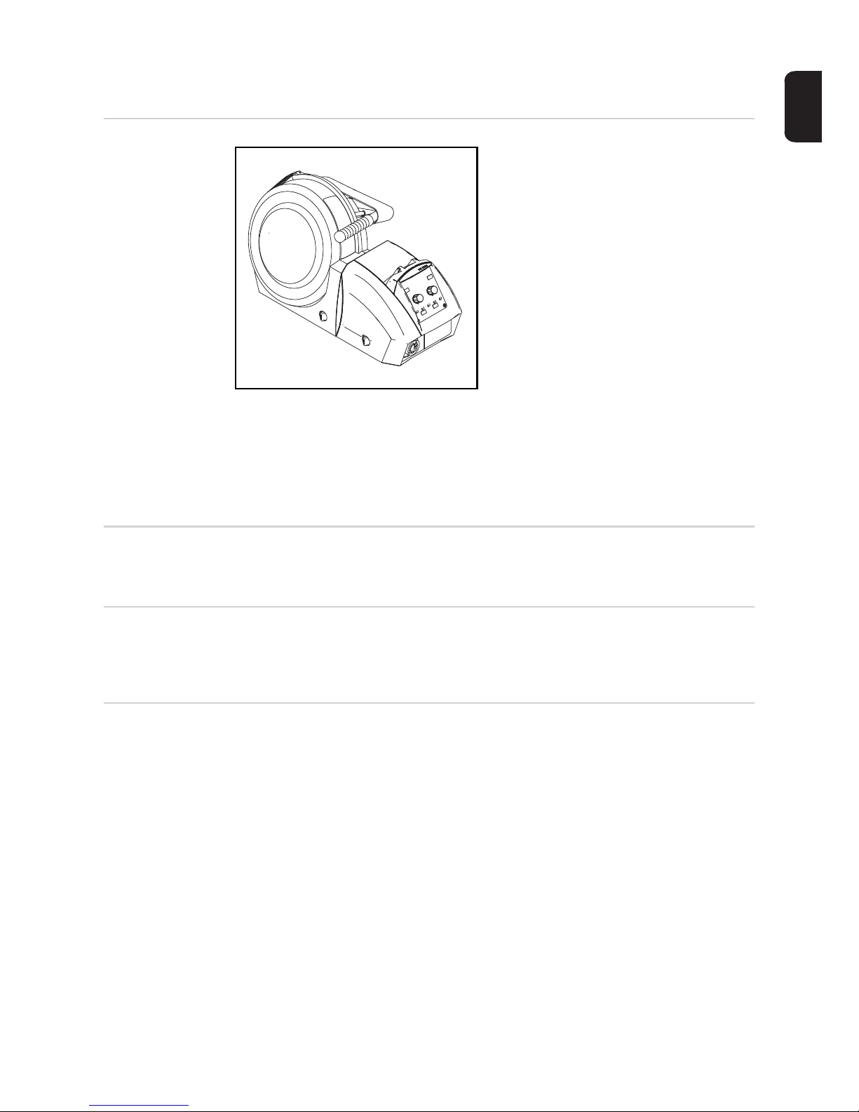
The standard version from the VR 5000 series has a cover for wirespools with a maximum diameter of 300 mm (11.81 in.).
Also available is the noSpool variant without an integrated wirespool holder. The
noSpool variant is particularly suitable for
robot and automated applications with an
external wire feeder.
The standard 4-roller drive has good wirefeeding properties. The wire-feed units from
the VR 5000 series are also suitable for
long hosepacks.
Due to their compact design, the VR 5000 wire-feed units can be used in many different
ways.
The device has a "Power limitation" safety feature. This means that the power source can
be operated at the power limit without compromising process safety. For more information,
see the "Welding mode" section.
Requirements The VR 5000 wire-feed units can be operated with the TransSteel 3500 / 5000 power
sources.
Application area The wire-feed units from the VR 5000 series are suitable for all shielding gas welding work
for steel applications and can be used with any of the standard shielding gases provided
for this purpose.
Warning notices
on the device
The wire-feed unit has safety symbols on the rating plate. The safety symbols must not be
removed or painted over. The symbols warn against operating the equipment incorrectly,
as this may result in serious injury and damage.
Page 22

22
Welding is dangerous. The following
basic requirements must be met:
- Welders must be sufficiently quali-
fied
- Suitable protective equipment
- Keep all persons not involved in
the welding process at a safe distance
Do not use the functions described here
until you have thoroughly read and understood the following documents:
- these operating instructions
- all the operating instructions for the
system components, especially
the safety rules
1.0-25 m/min
360A/100% 450A/60% 500A/40%
I
2
4.0 A
I
11
U11
24 V
U
12 I12 2.0 A24 V
IP 23
IEC 60 974-5/-10 Cl.A
A-4600 Wels
www.fronius.com
Model No.
Ser. No.
Part No.
40,0006,3035
Page 23
23
EN
Description of
Warning Notices
on the Device
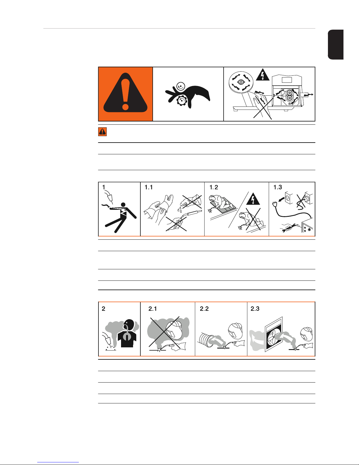
On certain device versions, warning notices are attached to the device.
The arrangement of the symbols may vary.
Warning! Watch Out!
There are possible hazards as shown by the symbols.
A Drive rolls can injure fingers.
B Welding wire and drive parts are at welding voltage during operation
Keep hands and metal objects away.
1. Electric shock can kill.
1.1 Wear dry insulating gloves. Do not touch electrode with bare hand. Do not wear
wet or damaged gloves.
1.2 Protect yourself from electric shock by insulating yourself from work and ground.
1.3 Disconnect input plug or power before working on machine
2. Breathing welding fumes can be hazardous to your health.
2.1 Keep your head out of the fumes.
2.2 Use forced ventilation or local exhaust to remove the fumes.
2.3 Use ventilating fan to remove fumes.
AB
Page 24

24
3 Welding sparks can cause explosion or fire.
3.1 Keep flammables away from welding. Don’t weld near flammables.
3.2 Welding sparks can cause fires.Have a fire extinguisher nearby and have a watchperson ready to use it.
3.3 Do not weld on drums or any closed containers.
4. Arc rays can burn eyes and injure skin.
4.1 Wear hat and safety glasses. Use ear protection and button shirt collar. Use welding helmet with correct shade of filter. Wear complete body protection.
5. Become trained and read the instructions before working on the machine or welding.
6. Do not remove or paint over (cover) the label.
* identifying number to order label from manufacturer
xx,xxxx,xxxx *
Page 25

Control elements and connections
Page 26

Page 27

27
EN
Description of the control panels
General information
The functions on the control panels are all arranged in a very logical way. The various welding parameters needed for welding are easy to select, by pressing the appropriate button,
and can easily be
- altered using buttons or the adjusting dial
- displayed on the digital display during welding
Thanks to the synergic function, whenever one parameter is altered, the appropriate
changes are automatically made to all the other welding parameters.
NOTE!
As a result of software updates, you may find that your device has certain functions
that are not described in these operating instructions, or vice versa.
Certain illustrations may also differ slightly from the actual controls on your device. However, these controls function in exactly the same way.
IMPORTANT! Welding parameters that must be entered on a wire-feed unit control panel
cannot be changed on the power source. Welding parameters can only be changed on the
wire-feed unit.
Safety
WARNING!
Operating the equipment incorrectly can cause serious injury and damage.
► Do not use the functions described until you have thoroughly read and understood
these operating instructions
► Do not use the functions described until you have thoroughly read and understood all
the operating instructions for the system components, especially the safety rules
Page 28
28
Manual control panel
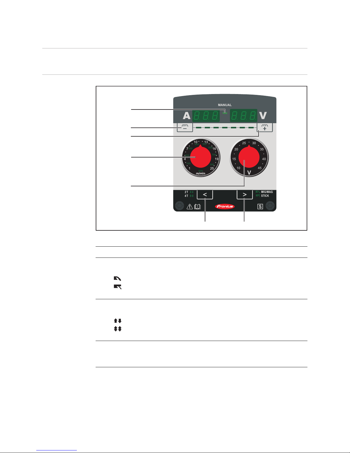
General The control panel allows straightforward manual setting of the welding parameters.
Manual control
panel
No. Function
(1) "Process" button
*)
for selecting the welding process
MIG/MAG welding
STICK manual metal arc welding
for selecting welding parameters in the Setup menu
(2) "Mode" button
for selecting the operating mode
2-step mode
4-step mode
for selecting welding parameters in the Setup menu
(3) Welding voltage adjuster
for selecting the welding voltage in V
The welding voltage is directly related to the arc length.
(4) Wire feed speed adjuster
for selecting the wire feed speed in m/min or ipm.
If the welding voltage (3) remains constant, the welding current increases as the
wire feed speed (4) increases
(6)
(5)
(5)
(4)
(3)
(2) (1)
Page 29

29
EN
(5) "Dynamic" buttons
for influencing the short-circuiting dynamic at the moment of droplet transfer
- ... harder, more stable arc
+ ... soft, low-spatter arc
(6) HOLD indicator
Every time you finish a welding operation, the actual values for welding current and
welding voltage are stored, and the HOLD indicator lights up.
Adjustment aid
for Manual control panel
For selected material/shielding gas combinations, the wire-feed unit includes adjustment
aids in the form of films that can be easily attached to and removed from the Manual control
panel. The adjustment aids have additional scales that correspond to the sheet thickness
used. If both the adjusters are set to the current value for the sheet thickness, this will produce a good basic setting for the respective material / shielding gas combination.
(1) Adjustment aid applies with the specified material / shielding gas combina-
tion
e.g.:
- Steel = Material
- Ø 1.0 mm = Wire diameter
- 100 % CO2 = Shielding gas
*) In conjunction with the VRD option, the currently selected welding process indica-
tor is simultaneously an additional indicator:
- The indicator is permanently lit: the Voltage Reduction Device (VRD) is active
and is limiting the output power to less than 35 V.
- The indicator starts to flash as soon as a welding action starts in which the output voltage can exceed 35 V.
Page 30

30
(2) Scales for sheet thickness
in mm
The two adjusters must be set to the appropriate value for the sheet thickness be-
ing used in order to obtain the basic setting according to the adjustment aid.
(3) Dynamic
Recommended dynamics settings are specified for three ranges of sheet thickness.
Keylock A keylock can be selected to prevent the settings from being inadvertently changed on the
control panel. As long as the keylock is active
- no settings can be made on the control panel
- only parameter settings can be retrieved
Activate/deactivate the keylock as follows:
Keylock activated:
The message "CLO | SEd" appears on the displays.
Keylock deactivated:
The message "OP | En" appears on the displays.
Service parameters
Various service parameters can be retrieved by pressing the "Dynamic" buttons at the
same time.
Opening the display
The first parameter ("Firmware version") is displayed, e.g. "1.00 | 4.21"
Selecting parameters
Available parameters
Press and hold the "Mode" button
Press the "Dynamic" button (right)
Release the "Mode" and "Dynamic" buttons
1
2
3
Press and hold the "Dynamic-" button
Press the "Dynamic+" button
Release the "Dynamic" buttons
Press the "Mode" and "Process" buttons to select the desired setup parameter
1
2
3
1
Page 31

31
EN
Explanation
Example:
1.00 | 4.21
Firmware version
Example:
2 | 491
Welding program configuration
Example:
r 2 | 290
Number of the currently selected welding program
Example:
iFd | 0.0
Motor current for wire drive in A
The value changes as soon as the motor is running.
654 | 32.1
= 65,432.1 hours
= 65,432 hours 6 mins
Indicates the actual arc time since using for the first time
Note: The arc time indicator is not suitable as a basis for calculating hiring fees, warranty services, etc.
2nd 2nd menu level for service engineers
Page 32
32
Synergic control panel
General The power source uses the Synergic control panel and certain general items of data such
as sheet thickness, filler metal, wire diameter and shielding gas to calculate the best welding parameters. As a result, stored knowledge is available at all times. All the parameters
can be adjusted manually. The Synergic control panel also allows parameters to be set
manually.
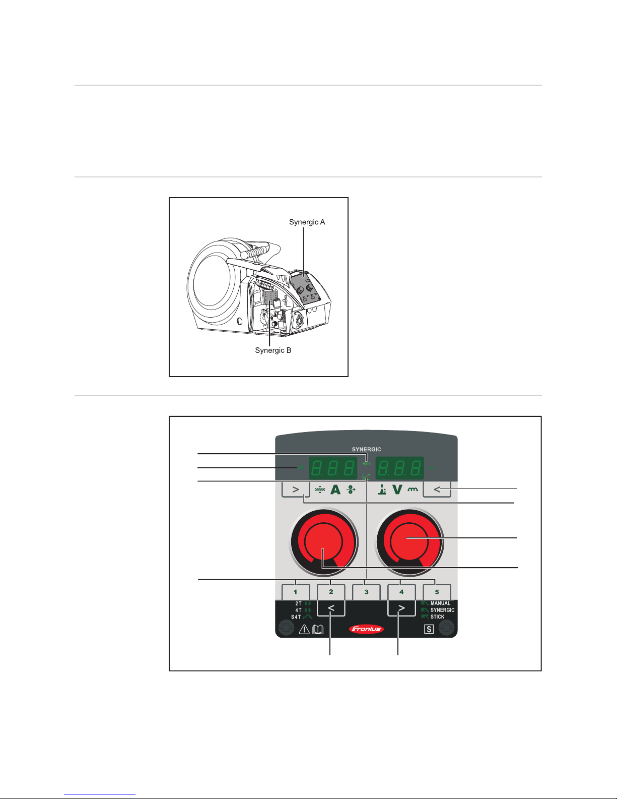
Control panel
splitting
The Synergic control panel is split.
Synergic A control panel
(9)
(8)
(7)
(4)
(6) (5)
(3)
(2)
(1)
(10)
Page 33
33
EN
No. Function
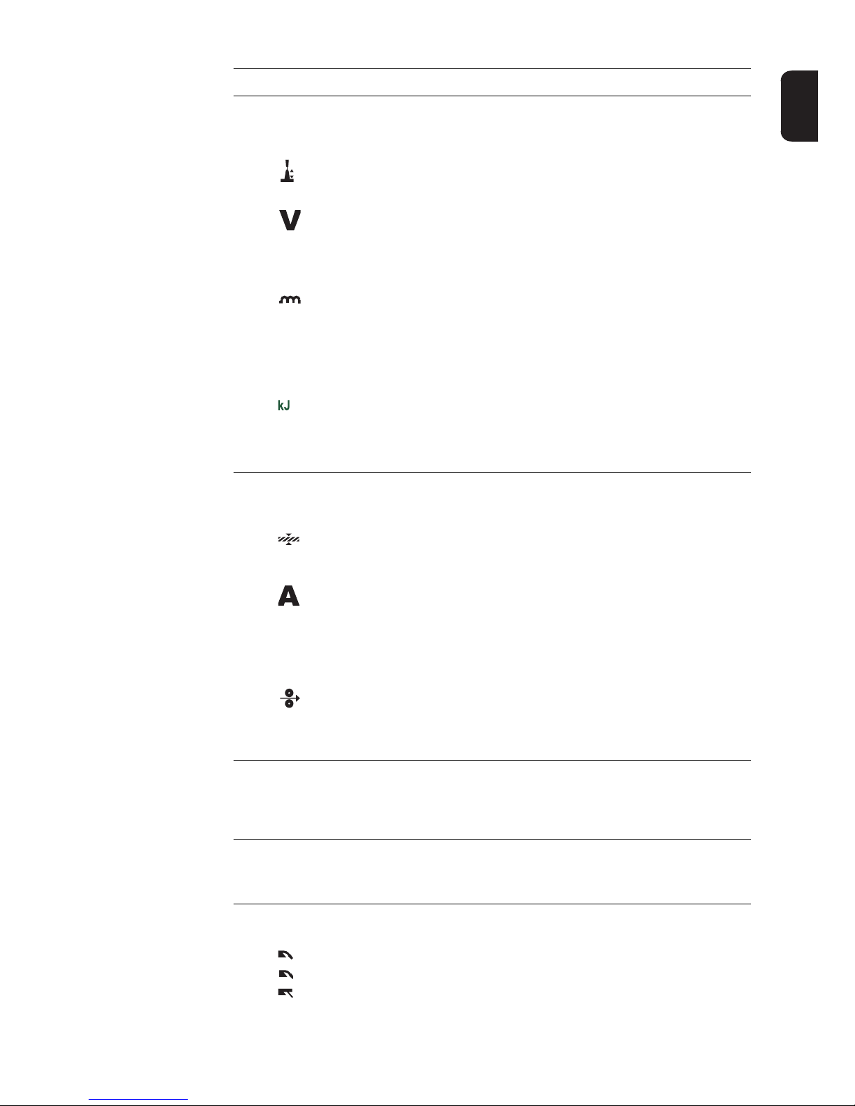
(1) "Parameter selection" button (right)
a) for selecting the following welding parameters
Arc length correction
for correcting the arc length
Welding voltage in V
*)
Before the start of welding, the device automatically displays a standard value
based on the programmed parameters. During welding, the actual value is
displayed.
Arc-force dynamic
for influencing the short-circuiting dynamic at the moment of droplet transfer
- ... harder, more stable arc
0 ... neutral arc
+ ... soft, low-spatter arc
Real Energy Input
for displaying the energy applied during the welding operation.
**)
b) for changing parameters in the Setup menu
(2) "Parameter selection" button (left)
a) for selecting the following welding parameters
Sheet thickness
Sheet thickness in mm or in.
Welding current
*)
Welding current in A
Before the start of welding, the device automatically displays a standard value
based on the programmed parameters. During welding, the actual value is
displayed.
Wire feed speed
*)
Wire feed speed in m/min or ipm.
b) for changing parameters in the Setup menu
(3) Adjusting dial (right)
for changing the arc length correction, welding voltage and arc-force dynamic parameters
for changing welding parameters in the Setup menu
(4) Adjusting dial (left)
for changing the sheet thickness, welding current and wire feed speed parameters
for selecting welding parameters in the Setup menu
(5) "Process" button
***)
for selecting the welding process
MANUAL - MIG/MAG standard manual welding
SYNERGIC - MIG/MAG standard synergic welding
STICK - manual metal arc welding
Page 34

34
(6) "Mode" button
for selecting the operating mode
2 T - 2-step mode
4 T - 4-step mode
S 4 T - Special 4-step mode
(7) "Save" buttons (Easy Job)
for saving up to 5 operating points
(8) Intermediate arc indicator
Between the dip transfer arc and the spray arc, a spatter-prone "intermediate arc"
occurs. The intermediate arc indicator lights up to draw attention to this critical area.
(9) HOLD indicator
Every time you finish a welding operation, the actual values for welding current and
welding voltage are stored, and the HOLD indicator lights up.
(10) SF - spot / stitch welding indicator
lights up if a value has been entered for the spot / stitch welding time Setup parameter (SPt) (spot or stitch welding operating mode is enabled)
Synergic B control panel overview
Three versions of the Synergic B control panel are available, as explained below:
- Steel
- Yard
- Steel USA
*) If one of these parameters is selected in the MIG/MAG standard synergic welding
process, then the synergic function ensures that all other parameters, including the
welding voltage parameter, are adjusted automatically.
**) The Real Energy Input display must be activated in level 2 of the Setup menu –
EnE parameter. The value continuously rises during welding in line with the permanently increasing energy yield. The final value at the end of welding remains stored
until welding starts again or the power source is switched back on - the "HOLD"
indicator lights up.
***) In conjunction with the VRD option, the currently selected welding process indica-
tor is simultaneously an additional indicator:
- The indicator is permanently lit: the Voltage Reduction Device (VRD) is active
and is limiting the output power to less than 35 V.
- The indicator starts to flash as soon as a welding action starts in which the output voltage can exceed 35 V.
Page 35
35
EN
Synergic B control panel
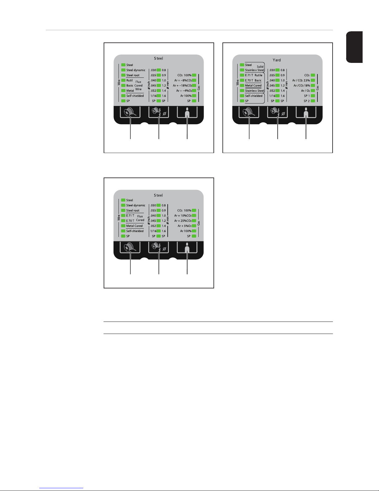
No. Function
(1) "Material" button
for selecting the filler metal to be used. Welding parameter SP is reserved for filler
metals.
When a material is selected, the LED behind the relevant filler metal lights up.
(1) (2) (3) (1) (2) (3)
Synergic B - Steel control panel Synergic B - Yard control panel
(1) (2) (3)
Synergic B - Steel USA control panel
Page 36
36
(2) "Wire diameter" button
For selecting the wire diameter to be used. Welding parameter SP is reserved for
additional wire diameters.
When a wire diameter is selected, the LED behind the relevant wire diameter lights
up.
(3) "Shielding gas" button
For selecting the shielding gas to be used. Welding parameter SP is reserved for
additional shielding gases.
When a shielding gas is selected, the LED behind the relevant shielding gas lights
up.
Keylock A keylock can be selected to prevent the settings from being inadvertently changed on the
control panel. As long as the keylock is active
- no settings can be made on the control panel
- only parameter settings can be retrieved
- any assigned "Save" button can be retrieved provided that an assigned "Save" button
was selected when the keylock was enabled
Activate/deactivate the keylock as follows:
Keylock activated:
The message "CLO | SEd" appears on the displays.
Keylock deactivated:
The message "OP | En" appears on the displays.
Service parameters
Various service parameters can be retrieved by pressing the "Parameter selection" buttons
at the same time.
Opening the display
The first parameter ("Firmware version") is displayed, e.g. "1.00 | 4.21"
Selecting parameters
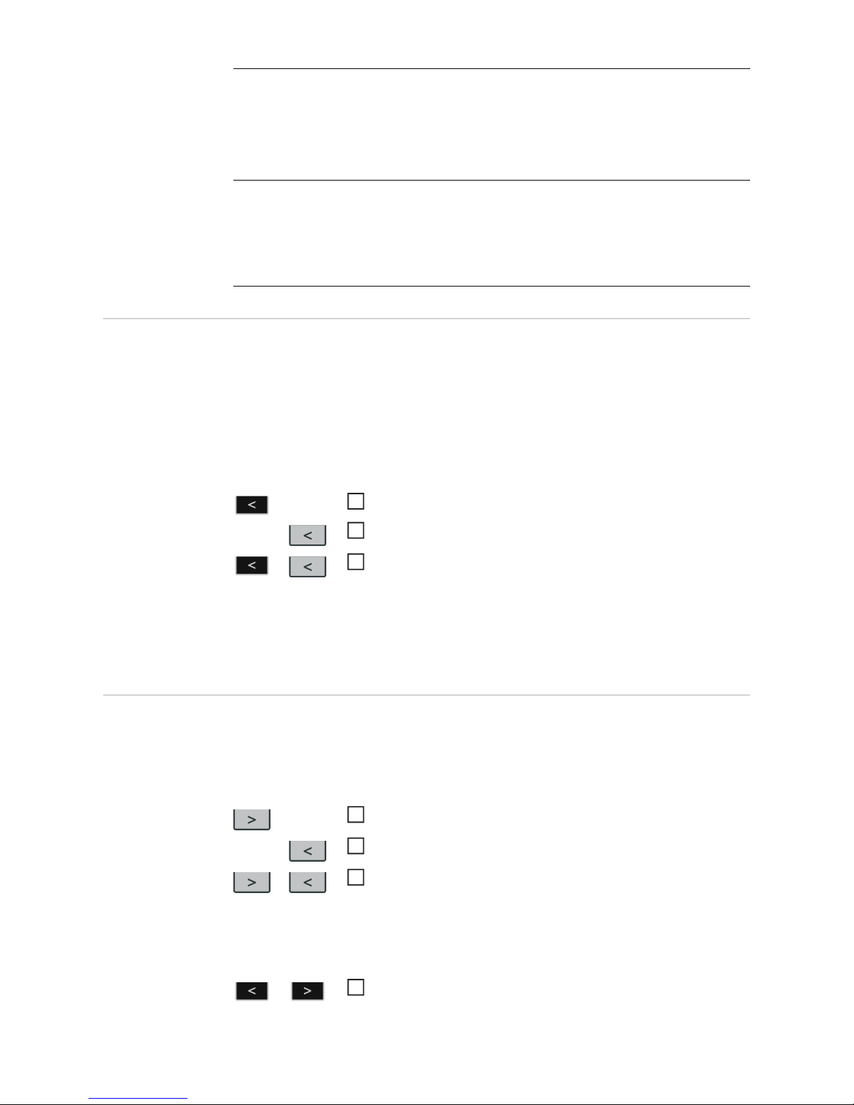
Press and hold the "Mode" button
Press the "Parameter selection" button (right)
Release the "Mode" and "Parameter Selection" buttons
1
2
3
Press and hold the "Parameter selection" button (left)
Press the "Parameter selection" button (right)
Release the "Parameter selection" buttons
Select the required setup parameter using the "Mode" and "Process" buttons or the left-hand adjusting dial
1
2
3
1
Page 37

37
EN
Available parameters
Explanation
Example:
1.00 | 4.21
Firmware version
Example:
2 | 491
Welding program configuration
Example:
r 2 | 290
Number of the currently selected welding program
Example:
iFd | 0.0
Motor current for wire drive in A
The value changes as soon as the motor is running.
654 | 32.1
= 65,432.1 hours
= 65,432 hours 6 mins
Indicates the actual arc time since using for the first time
Note: The arc time indicator is not suitable as a basis for calculating hiring fees, warranty services, etc.
2nd 2nd menu level for service engineers
Page 38
38
Connections and mechanical components
Overview of connections for the
welding torch
An overview of the connections available for the welding torch can be found in the spare
parts list in the Appendix.
Front of wire-feed
unit
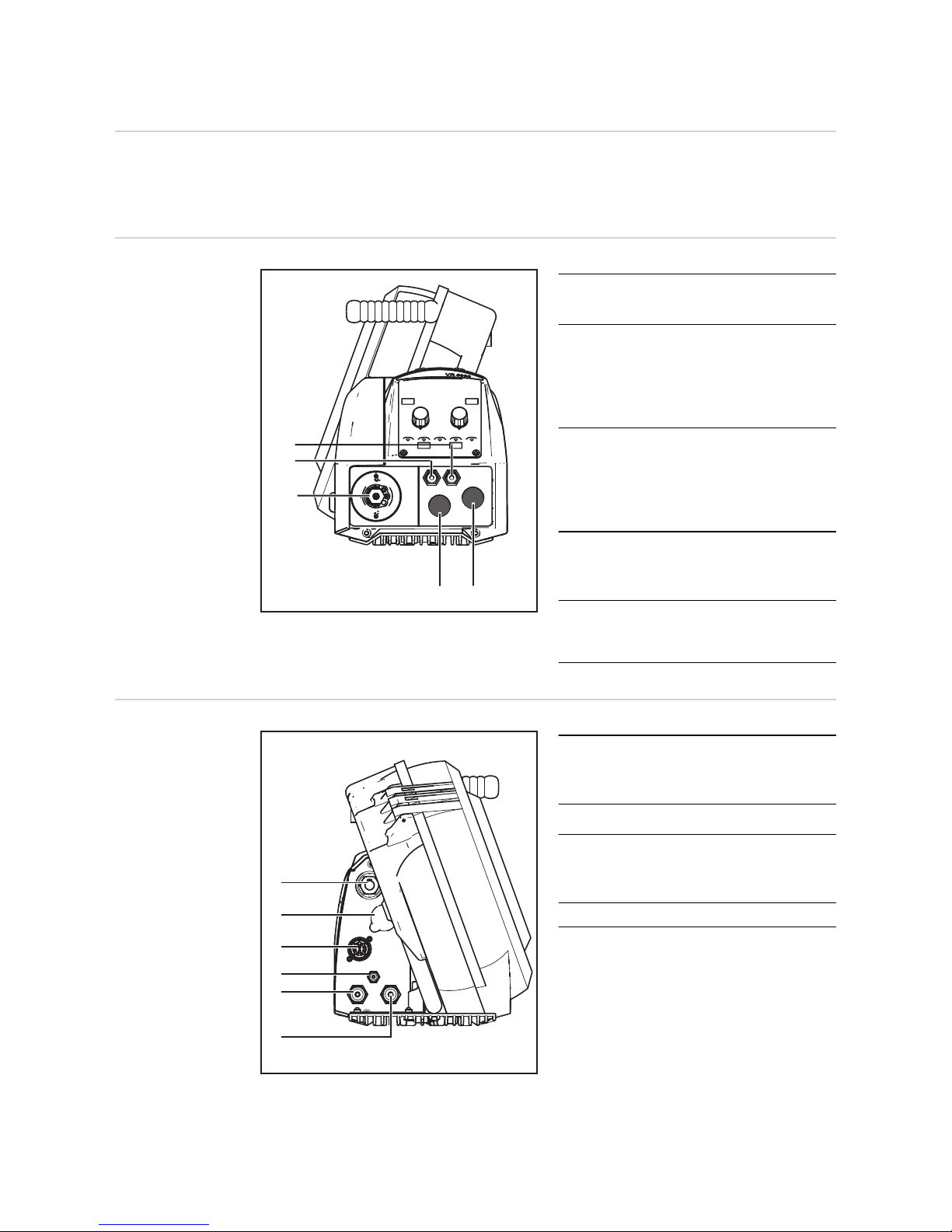
(1) Welding torch connection
for connecting the welding torch
(2) Coolant flow connection (blue) -
option
when the optional water connection
is installed, otherwise blanking cover
(3) Coolant return connection (red) -
option
when the optional water connection
is installed, otherwise blanking cover
(4) Position
for option (+) current socket with
bayonet latch
(5) Position
for LocalNet connection socket option
Rear of wirefeeder
(1) (+) current connection with bayo-
net latch
for interconnecting hosepack
(2) Blanking cover
(3) Enhanced LocalNet connection
for enhanced LocalNet with lines for
motor supply and motor control
(4) Shielding gas connection
(4)
(5)
(1)
(2)
(3)
(1)
(2)
(3)
(4)
(5)
(6)
Page 39
39
EN
(5) Coolant return connection (red) - option
when the optional water connection is installed, otherwise blanking cover
(6) Coolant flow connection (blue) - option
when the optional water connection is installed, otherwise blanking cover
Wire-feed unit
side
No. Function
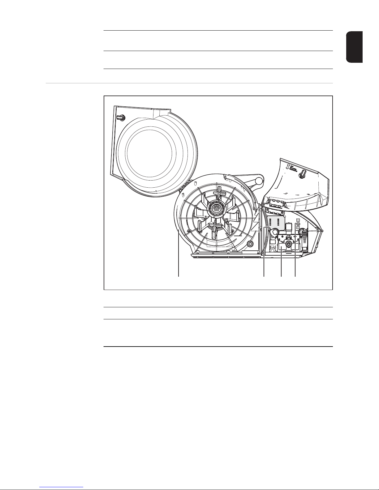
(1) Holder for braked wirespool
for holding standard wirespools with a max. diameter of 300 mm (11.81 in) and
max. weight of 19 kg (41.89 lbs.)
(2) Synergic control panel section B
in conjunction with the Synergic control panel
(1) (2) (3) (4)
Page 40
40
(3) 4-roller drive
(4) Optional Wire threading / Gas test button
Push button downwards:
for threading the wire electrode into the welding torch hosepack with no accompa-
nying flow of gas or current. While the button is being held down, the wire-feed unit
runs at wire threading speed.
Push button upwards:
to set the required quantity of gas at the pressure regulator.
- Tap button once: shielding gas flows out
- Tap button again: shielding gas flow stops
If the "Gas test" button is not tapped again, the shielding gas flow will stop after 30
s.
Wire-feed unit underside
No. Function
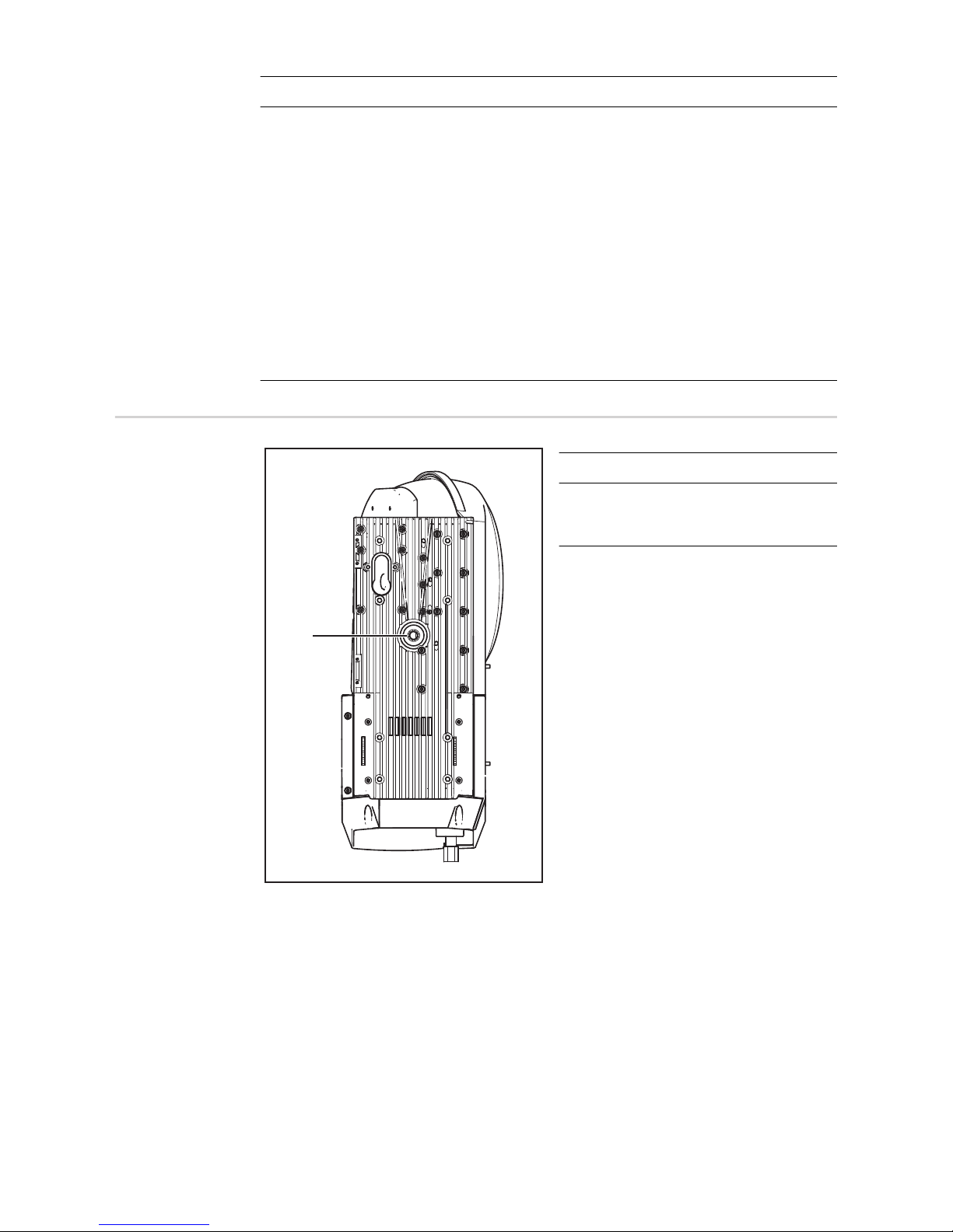
(1) Socket for swivel pin
for placing the wire-feed unit on the
swivel pin in the swivel pin holder
(1)
Page 41

Installation and commissioning
Page 42

Page 43
43
EN
Before commissioning
Safety
WARNING!
Operating the equipment incorrectly can cause serious injury and damage.
Do not use the functions described until you have thoroughly read and understood the following documents:
► these operating instructions
► all the operating instructions for the system components, especially the safety rules
WARNING!
An electric shock can be fatal.
If the power source is connected to the mains electricity supply during installation, there is
a high risk of very serious injury and damage. Before carrying out any work on the device
make sure that:
► the power source mains switch is in the "O" position
► the power source is unplugged from the mains
Intended purpose The device is intended exclusively for wire feeding in MIG/MAG welding.
Utilisation for any other purpose, or in any other manner, shall be deemed to be not in accordance with the intended purpose.
The manufacturer shall not be held liable for any damages arising from such usage.
Utilisation in accordance with the "intended purpose" also comprises
- following all the information in the operating instructions
- carrying out all the specified inspection and servicing work
Setup regulations
WARNING!
If one of these devices falls or topples over, it could cause serious or even fatal injury.
Place devices, upright consoles and trolleys on a solid, level surface in such a way that
they remain stable. If a swivel pin holder is being used, make sure that the wire-feed unit
is seated securely on the swivel pin.
The VR 5000 standard version with an integrated wirespool holder is tested to IP23 protection, meaning:
- protection against penetration by solid foreign bodies with diameters exceeding 12.5
mm (0.49 in.)
- protection against direct sprays of water at any angle up to 60° from the vertical
The VR 5000 standard version with an integrated wirespool holder can be set up and operated outdoors in line with IP23 protection. Avoid direct wetting (e.g. from rain).
The VR 5000 noSpool without an integrated wirespool holder is tested to IP20 protection,
meaning:
- protection against penetration by solid foreign bodies with diameters exceeding 12.5
mm (0.49 in.)
- no protection against water
Page 44

44
The VR 5000 noSpool without an integrated wirespool holder may only be set up and operated in closed areas.
Page 45
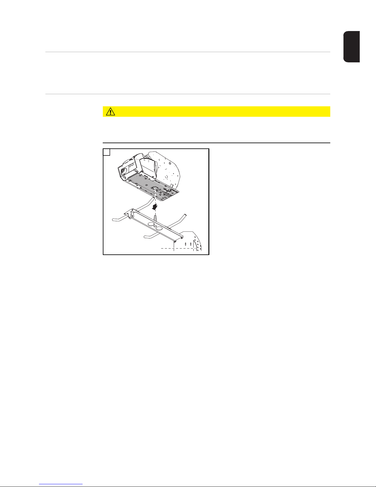
45
EN
Placing wire-feed unit on power source
General information
The wire-feed units can be placed on the power source if a swivel pin holder is available,
e.g.:
- VR 5000 swivel pin holder, for use with the PickUp 5000 trolley
Placing wire-feed
unit on power
source
CAUTION!
Danger from falling wire-feed unit.
Make sure that the wire-feed unit is located securely on the swivel pin and that the devices,
upright consoles and trolleys are stable.
1
1
1
Page 46
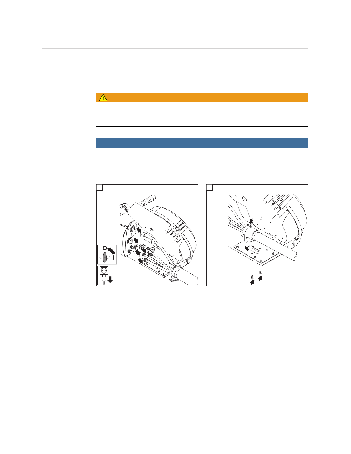
46
Connecting wire-feed unit to power source
General information
The wire-feed unit is connected to the power source using the interconnecting hosepack.
Connecting wirefeed unit to power
source
WARNING!
Fitting the equipment incorrectly can cause serious injury and damage.
Do not carry out the steps described here until you have read and completely understood
all the operating instructions.
NOTE!
When connecting the interconnecting hosepack, check that
► all connections are connected properly
► all cables, leads and hosepacks are undamaged and correctly insulated
1 2
IMPORTANT! To prevent wear and tear, form a loop towards the inside when connecting
the cables. A strain-relief device is not provided in the case of 1.2 m (3 ft. 11.24 in.) interconnecting hosepacks.
1
2
7
4
5
6
3
1
2
1
3
4
2
Page 47
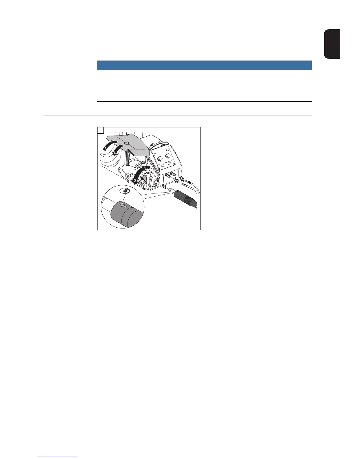
47
EN
Connecting the welding torch
Safety
NOTE!
When connecting the welding torch, check that
► all connections are connected properly
► all cables, leads and hosepacks are undamaged and correctly insulated.
Connecting MIG/
MAG manual
welding torches
1
* when the optional water connection and
the water-cooled welding torch are fitted
1
Page 48
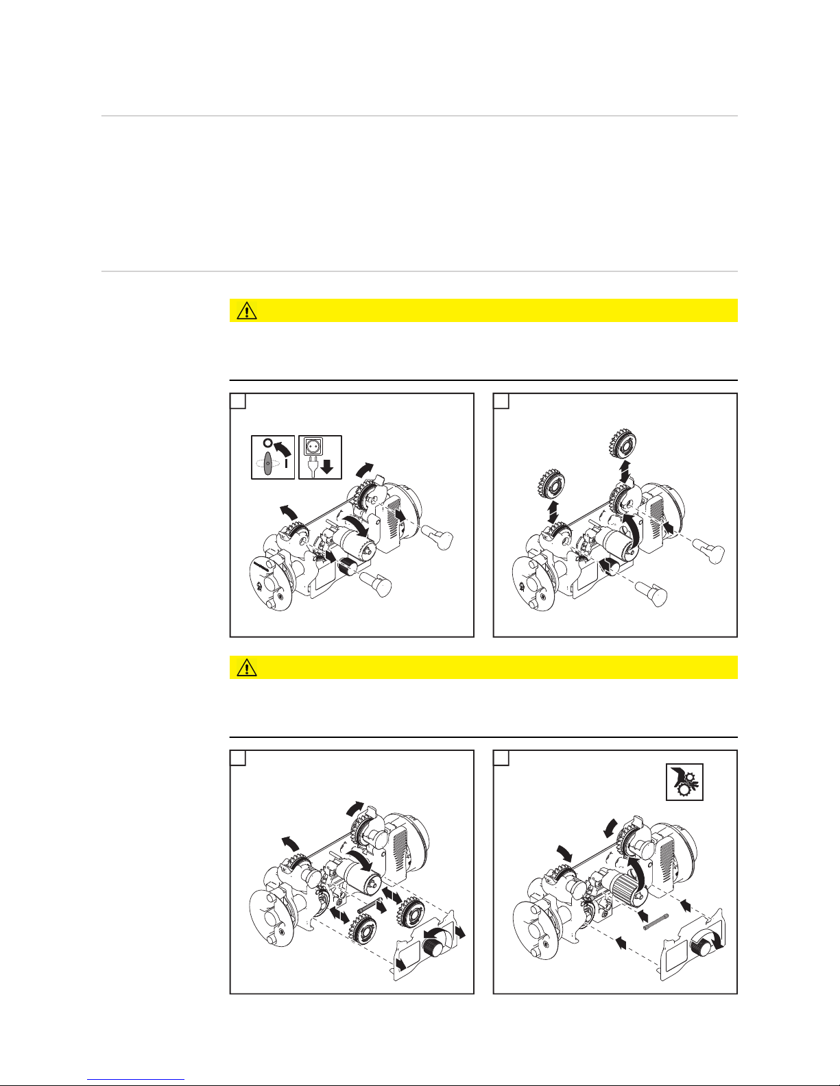
48
Inserting/replacing feed rollers
General In order to achieve optimum wire electrode feed, the feed rollers must be suitable for the
diameter and alloy of the wire being welded.
IMPORTANT! Only use feed rollers that match the wire electrode.
An overview of the feed rollers available and their possible areas of use can be found in
the spare parts lists.
Inserting/replacing feed rollers
CAUTION!
Risk of injury if the feed roller holders fly upwards.
► When unlocking the clamping lever, keep fingers away from the area to the left and
right of the lever.
1 2
CAUTION!
Risk of crushing by exposed feed rollers.
► Always fit the protective cover of the 4-roller drive after inserting or changing a feed roll-
er.
1 2
2
1
4
4
5
6
3
1
6
3
31
2
4
5
7
2
3
8
6
7
9
3
1
2
2
5
4
4
3
4
5
5
6
1
2
3
4
Page 49
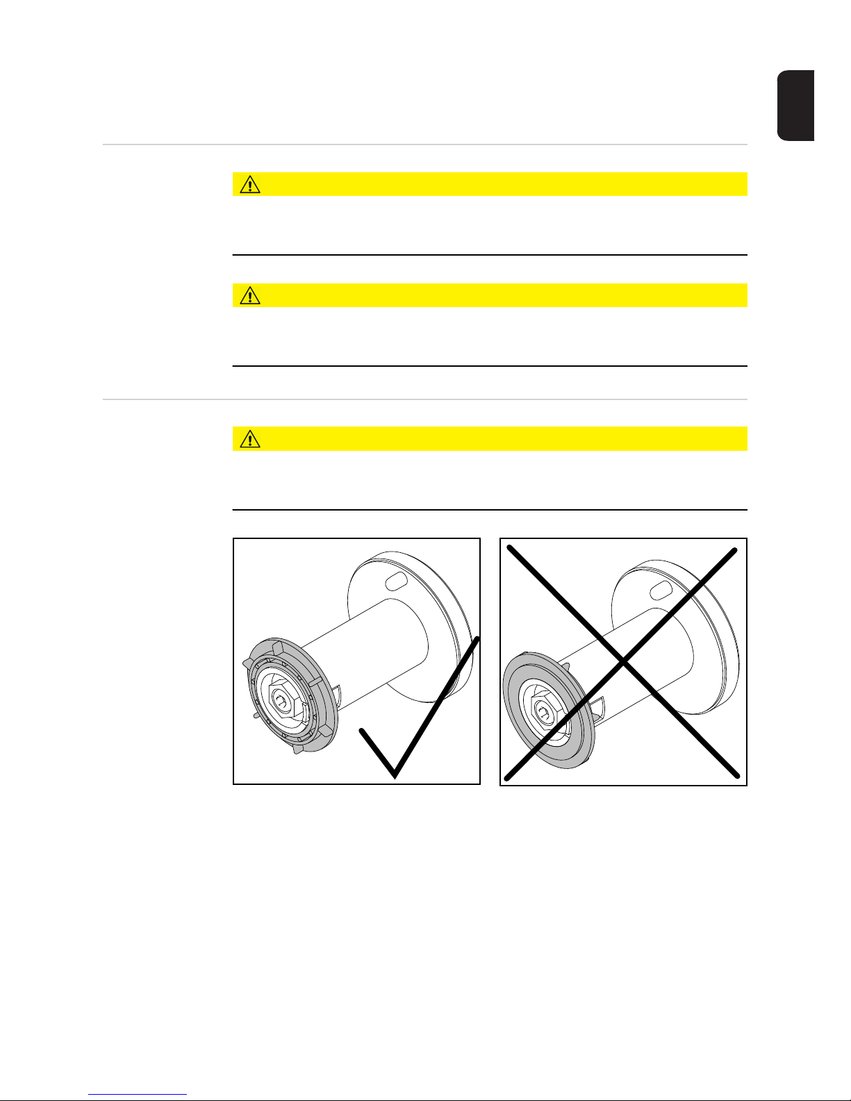
49
EN
Inserting the wirespool, inserting the basket-type
spool
Safety
CAUTION!
Risk of injury from springiness of spooled wire electrode.
When inserting the wirespool/basket-type spool, hold the end of the wire electrode firmly
to avoid injuries caused by the wire electrode springing back.
CAUTION!
Risk of injury from falling wirespool / basket-type spool.
Make sure that the wirespool or basket-type spool with adapter is fitted securely to the wirespool holder.
Inserting the wirespool
CAUTION!
Risk of injury and material damage if the wirespool topples over because the locking
ring has been placed the wrong way round.
Always place the locking ring as shown in the diagram on the left.
Page 50
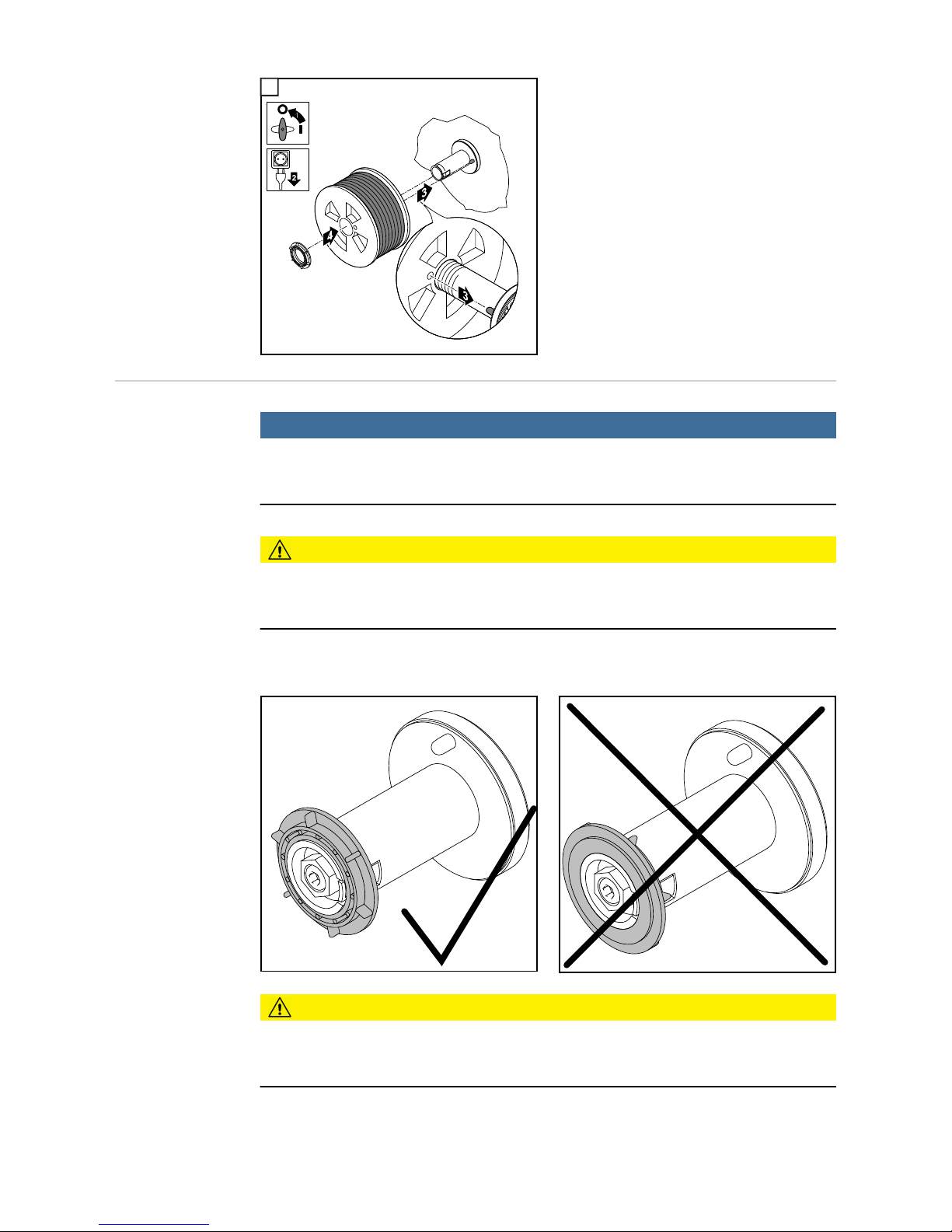
50
1
Inserting the basket-type spool
NOTE!
When working with basket-type spools, only use the basket-type spool adapter included in the scope of supply.
CAUTION!
Risk of injury and material damage if the basket-type spool topples over because the
locking ring has been placed the wrong way round.
Always place the locking ring as shown in the diagram on the left.
CAUTION!
Risk of injury and material damage from falling basket-type spool.
Place the basket-type spool on the adapter provided in such a way that the bars on the
spool are inside the adapter guideways.
1
Page 51
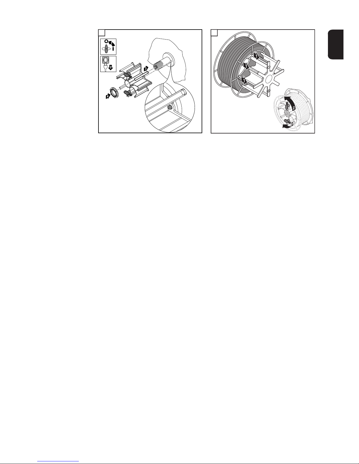
51
EN
1 2
1
2
Page 52
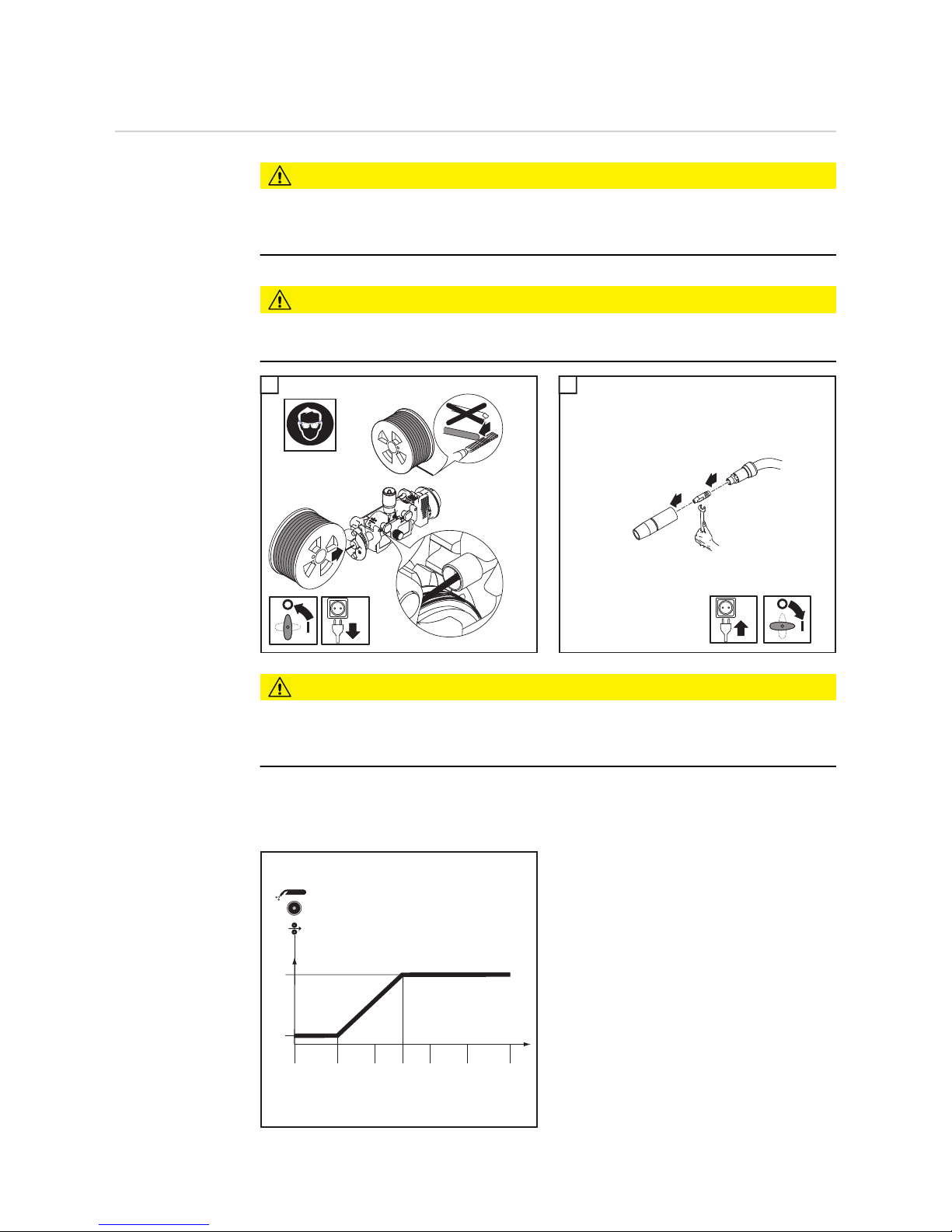
52
Feeding in the wire electrode
Feeding in the
wire electrode
CAUTION!
Risk of injury from springiness of spooled wire electrode.
When inserting the wire electrode into the 4-roller drive, hold the end of the wire electrode
firmly to avoid injuries caused by the wire springing back.
CAUTION!
Risk of damage to the welding torch from sharp end of wire electrode.
Deburr the end of the wire electrode well before feeding in.
1 2
CAUTION!
Risk of injury from wire electrode emerging at speed.
When pressing the Feeder inching button or the torch trigger, keep the welding torch away
from your face and body, and wear suitable protective goggles.
IMPORTANT! To facilitate the exact positioning of the wire electrode, the following sequences are possible when the Feeder inching button is pressed and held down.
- Hold the button for up to one second
... the wire feed speed stays at 1 m/min
or 39.37 ipm for the first second.
- Hold the button for up to 2.5 seconds
... after one second has elapsed, the
wire feed speed increases at a uniform
rate over the next 1.5 seconds.
- Hold the button for more than 2.5 se-
conds ... after 2.5 seconds, the wire is
fed at a constant rate equal to the wire
feed speed set for the Fdi welding parameter.
2
1
4
3
1
4
1
2
3
2
Fdi
1
23
4
5
2,5
1
t (s)
(m/min, ipm)
Page 53
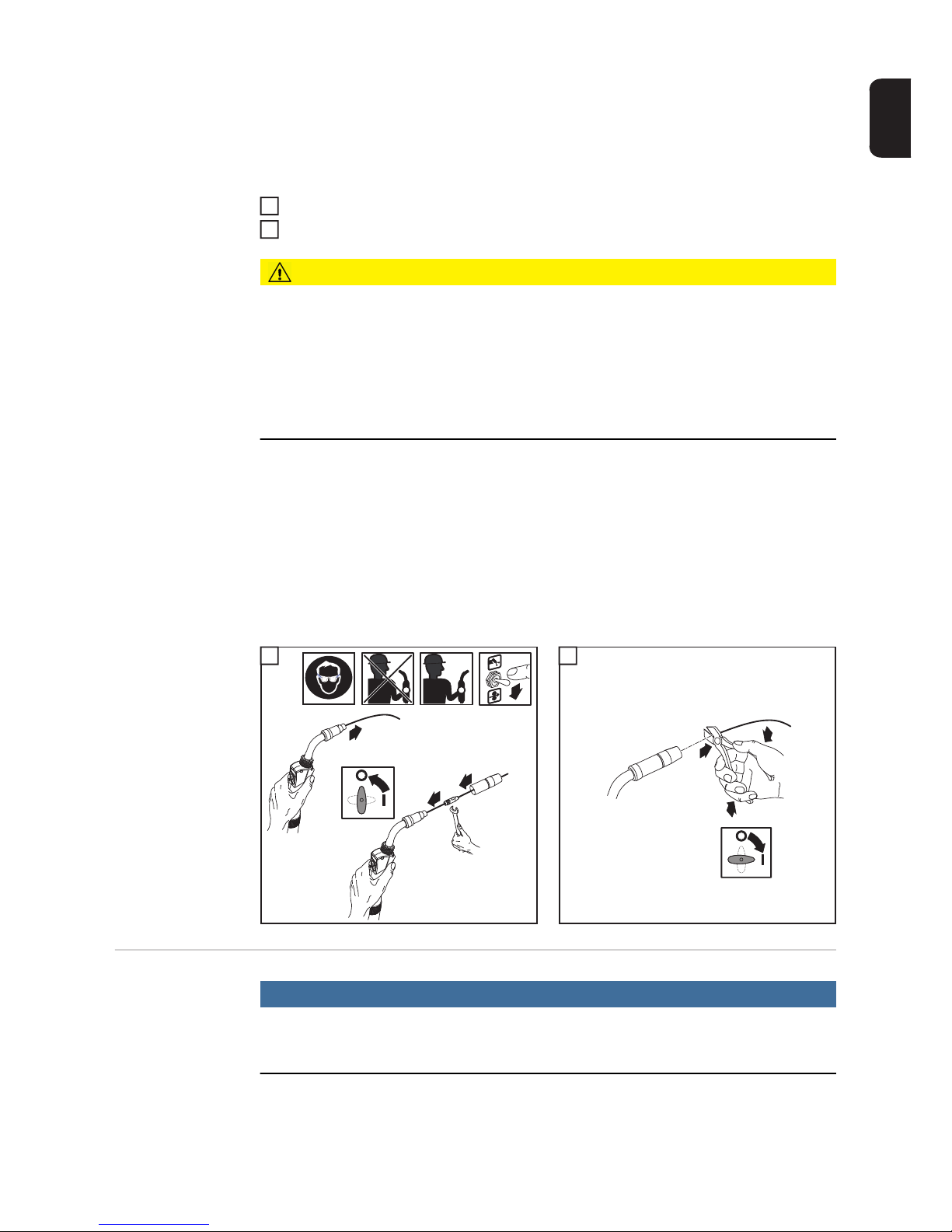
53
EN
If the Feeder inching button is released and pressed again before one second has elapsed,
the sequence starts again from the beginning. This makes it possible to continuously position the wire at a low wire feed speed of 1 m/min or 39.37 ipm where necessary.
If there is no Feeder inching/Gas test button, the torch trigger can be used in the same
way. Before using the torch trigger for wire threading, proceed as follows:
Press the Mode button to select 2-step mode
Set the "Ito" parameter to "Off" in the set-up menu
CAUTION!
Risk of injury and damage from electric shock and from the wire electrode emerging
at speed from the torch.
When pressing the torch trigger:
► keep the welding torch away from your face and body
► wear suitable protective goggles
► do not point the welding torch at people
► make sure that the wire electrode does not touch any conductive or earthed parts, such
as the housing, etc.
IMPORTANT! If the torch trigger is pressed instead of the Feeder inching/Gas test button, the welding wire runs at the feeder creep speed (depending on the welding program)
for the first 3 seconds. After these 3 seconds, wirefeeding is briefly interrupted.
The welding system detects that the welding process should not start, but that the wire is
to be threaded. At the same time, the gas solenoid valve closes, and the welding voltage
on the wire electrode is switched off.
If the torch trigger is held down, wirefeeding restarts immediately without shielding gas and
welding voltage, and the process continues as described above.
1 2
Setting the contact pressure
NOTE!
Set the contact pressure in such a way that the wire electrode is not deformed but
nevertheless ensures proper wirefeeding.
1
2
2
4
5
3
1
3
1
1
2
3
4
Page 54
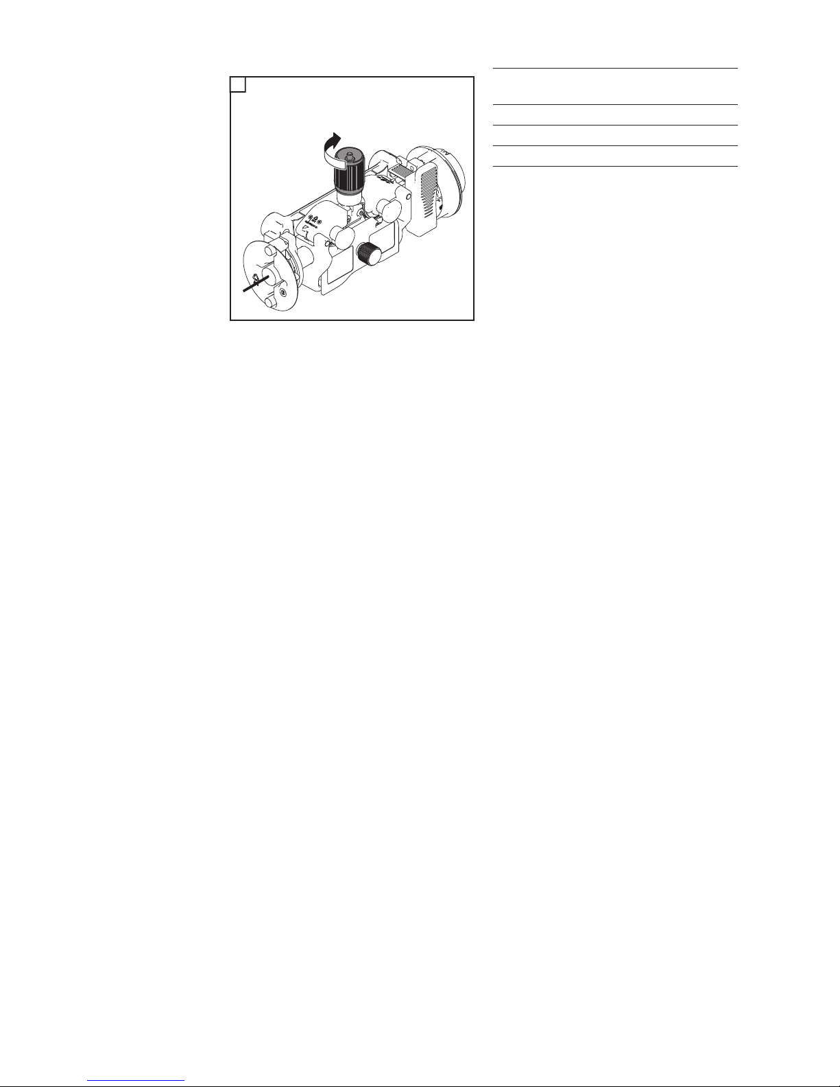
54
1
Contact pressure
standard values
U-groove rollers
Steel 4 - 5
CrNi 4 - 5
Tubular cored electrodes 2 - 3
1
1
Page 55
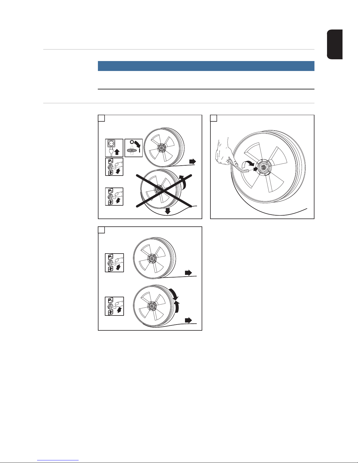
55
EN
Adjust the brake
General
NOTE!
After releasing the torch trigger the wirespool must stop unreeling.
If it continues unreeling, readjust the brake.
Adjusting the
brake
1 2
3
1
4
STOP
6
7
1
2
3
5
1
2
1
2
2
4
STOP
OK
1
3
3
Page 56
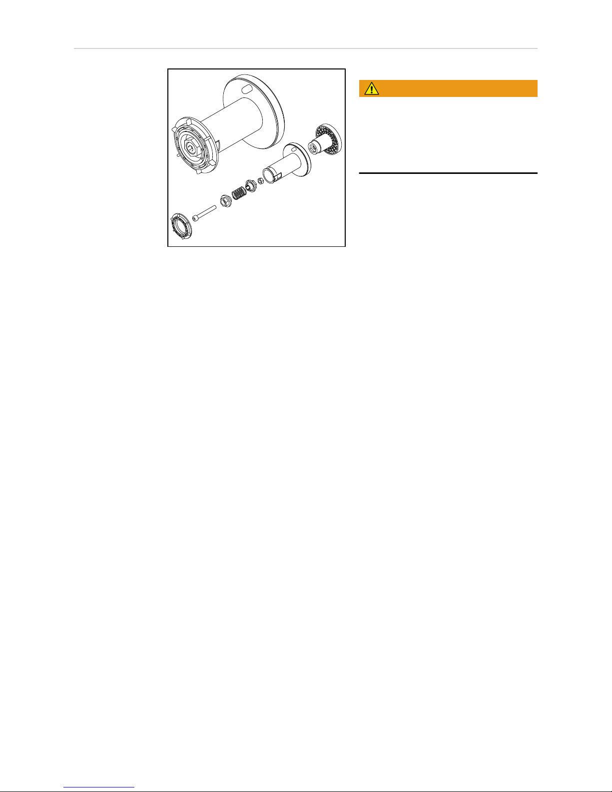
56
Design of the
brake
WARNING!
Fitting the equipment incorrectly can
cause serious injury and damage.
► Do not dismantle the brake.
► Maintenance and servicing of brakes is
to be carried out by trained, qualified
personnel only.
The brake is only available as a complete
unit.
This illustration is for information purposes
only.
Page 57

57
EN
Start-up
General information
WARNING!
Operating the equipment incorrectly can cause serious injury and damage.
Do not use the functions described until you have thoroughly read and understood the following documents:
► these operating instructions
► all the operating instructions for the system components, especially the safety rules
The wire-feed unit is commissioned by pressing the torch trigger (for manual applications)
or by means of a welding start-up signal (for automatic applications).
Requirements When commissioning the wire-feed unit, the following requirements must be met:
- Wire-feed unit connected to the power source using the interconnecting hosepack
- Welding torch connected to the wire-feed unit
- Feed rollers inserted into the wire-feed unit
- Wirespool or basket-type spool and adapter inserted in the wire-feed unit
- Wire electrode fed in
- Feed roller contact pressure set
- Brake adjusted
- All covers closed, all side panels in place, all protection devices intact and in their
proper place
Page 58

58
Page 59

Welding
Page 60

Page 61

61
EN
Power limitation
Safety function "Power limitation" is a safety function for MIG/MAG welding. This means that the power
source can be operated at the power limit whilst maintaining process safety.
Wire feed speed is a determining parameter for welding power. If it is too high, the arc gets
smaller and smaller and may be extinguished. In order to prevent this, the welding power
is lowered.
For the selected "MIG/MAG standard synergic welding" process, the symbol for the
"Wire feed speed" parameter flashes as soon as the safety function trips. The flashing continues until the next welding start-up, or until the next parameter change.
If the "Wire feed speed" parameter is selected, the reduced value for wire feed
speed is displayed.
Page 62
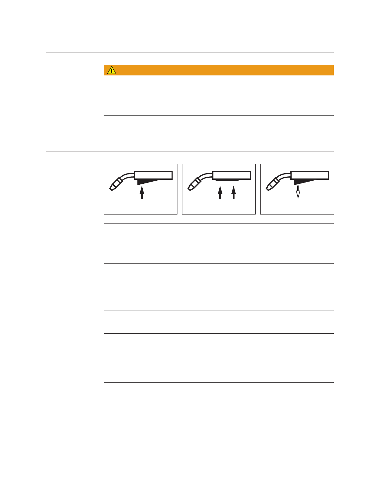
62
MIG/MAG modes
General
WARNING!
Operating the equipment incorrectly can cause serious injury and damage.
Do not use the functions described until you have thoroughly read and understood the following documents:
► these operating instructions
► all the operating instructions for the system components, especially the safety rules
For details of the meaning, settings, setting range and units of the available welding parameters (e.g. gas pre-flow time), please refer to the "Set-up parameters" section.
Symbols and
their explanations
Press the torch trigger Hold the torch trigger Release the torch trigger
GPr
Gas pre-flow time
I-S
Starting current
can be increased or decreased depending on the application
SL
Slope: the starting current is continuously lowered as far as the welding current and the
welding current as far as the final current
I
Welding-current phase: uniform thermal input into the base material, whose temperature
is raised by the advancing heat
I-E
Final current
for filling the end-crater.
GPo
Gas post-flow time
SPt
Spot welding time / stitch welding time
SPb
Stitch pause time
Page 63
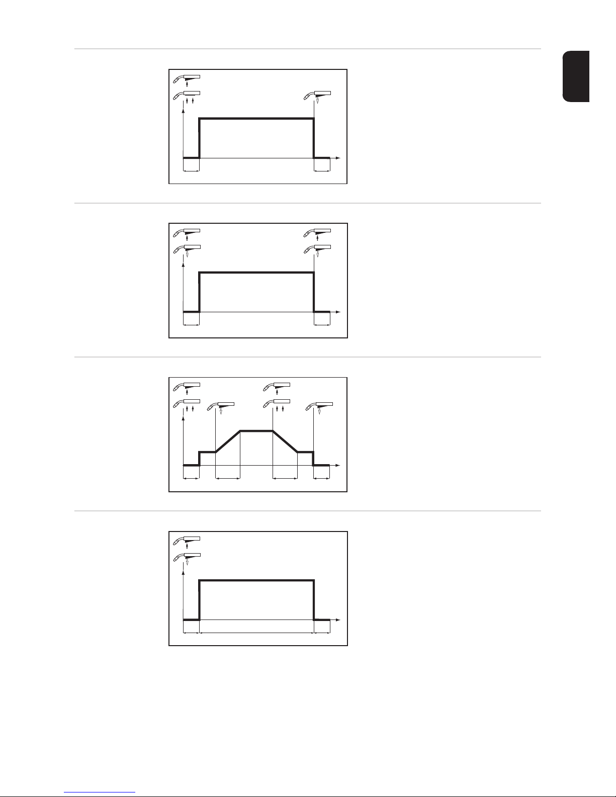
63
EN
2-step mode "2-step mode" is suitable for
- Tacking work
- Short weld seams
4-step mode
"4-step mode" is suitable for longer weld
seams.
Special 4-step
mode
Special 4-step mode allows the starting and
final current to be configured in addition to
the advantages of 4-step mode.
Spot welding
The "Spot welding" mode is suitable for
welded joints on overlapped sheets.
I
GPr
GPo
t
I
+
I
GPr
GPo
t
I
+
+
+ +
I
GPr
I-S I-E
SL SL
GPo
t
I
I
GPr
GPo
SPt
t
I
+
Page 64
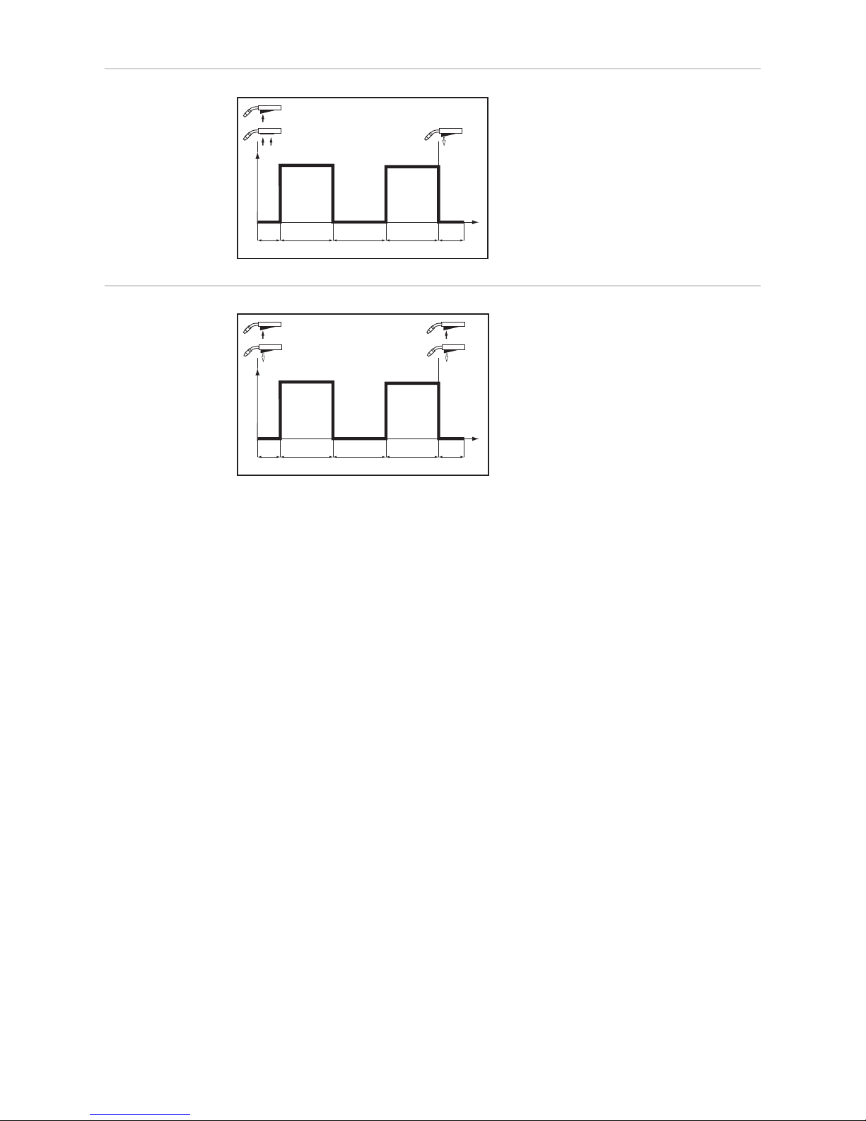
64
2-step stitch
welding
The "2-step stitch welding" mode is suitable
for welding short weld seams on thin
sheets, to prevent the weld seams from
dropping through the base material.
4-step stitch
welding
The "4-step stitch welding" mode is suitable
for welding longer weld seams on thin
sheets, to prevent the weld seams from
dropping through the base material.
I
GPr SPt SPtSPb
GPo
t
I
+
+ +
I
GPr SPt SPtSPb
GPo
t
I
Page 65
65
EN
MIG/MAG welding
Safety
WARNING!
Operating the equipment incorrectly can cause serious injury and damage.
Do not use the functions described until you have thoroughly read and understood the following documents:
► these operating instructions
► all the operating instructions for the system components, especially the safety rules
WARNING!
An electric shock can be fatal.
If the power source is connected to the mains electricity supply during installation, there is
a high risk of very serious injury and damage. Before carrying out any work on the device
make sure that:
► the power source mains switch is in the "O" position
► the power source is unplugged from the mains
General tasks before MIG/MAG
welding
Only where cooling units and a water-cooled welding torch are used:
Connect the water hoses of the welding torch to the correct plug-type connectors on
the wire-feed unit
Plug in the mains plug
Move the mains switch to the "I" position:
- all the indicators on the control panel light up briefly
- where applicable, the cooling unit starts to run
IMPORTANT! Follow the safety rules and note operating conditions in the cooling unit operating instructions.
Overview MIG/MAG welding is composed of the following sections:
- MIG/MAG standard synergic welding
- MIG/MAG standard manual welding
1
2
3
Page 66

66
MIG/MAG standard synergic welding
General The MIG/MAG standard synergic welding process is only available in combination with the
Synergic control panel.
MIG/MAG standard synergic
welding
On Synergic B control panel:
Press the Material button to select the filler metal to be used.
Assignment of the SP position depends on the welding database used for the power
source.
Press the Wire diameter button to select the diameter of the wire electrode to be used.
Assignment of the SP position depends on the welding database used for the power
source.
Press the Shielding gas button to select the shielding gas to be used.
Assignment of the SP position depends on the welding database used for the power
source.
On Synergic A control panel:
Press the Process button to select the desired welding process:
MIG/MAG standard synergic welding
Press the Mode button to select the desired MIG/MAG mode:
2-step mode
4-step mode
Special 4-step mode
IMPORTANT! Under certain circumstances, welding parameters that have been set
on a control panel of a system component (TR 2000 and TR 3000 remote control units
or robot interface) cannot be changed on the control panel of the wire-feed unit.
Press the Parameter selection buttons to select the welding parameters to be used to
specify the welding power:
Sheet thickness
Welding current
Wire feed speed
Welding voltage
Use the appropriate adjusting dial to set the relevant welding parameters.
The welding parameter values are shown in the digital display located above them.
All welding parameter set values remain stored until the next time they are changed. This
applies even if the power source is switched off and on again in the meantime.
1
2
3
4
5
6
7
Page 67
67
EN
To display the actual welding current during welding:
- Press the Parameter selection button to select the welding current parameter
- The actual welding current is shown on the digital display during welding.
Open the gas cylinder valve
Set the shielding gas flow rate:
If there is a Feeder inching/Gas test button:
- Press the Feeder inching/Gas test button upwards
- Turn the adjusting screw on the underside of the pressure regulator until the pres-
sure gauge shows the required gas flow rate
- Press the Feeder inching/Gas test button upwards again
If there is no Feeder inching/Gas test button:
- Press the Mode button to select 2-step mode
- Set the "Ito" parameter to "Off" in the set-up menu
- Disengage the feed rollers
CAUTION!
Risk of injury and damage from electric shock and from the wire electrode emerging
at speed from the torch.
When pressing the torch trigger:
► keep the welding torch away from your face and body
► wear suitable protective goggles
► do not point the welding torch at people
► make sure that the wire electrode does not touch any conductive or earthed parts, such
as the housing, etc.
- press and hold the torch trigger
- turn the adjusting screw on the underside of the pressure regulator until the pres-
sure gauge shows the required shielding gas flow rate
- release the torch trigger
- engage the feed rollers
CAUTION!
Risk of injury and damage from electric shock and from the wire electrode emerging
at speed from the torch.
When pressing the torch trigger:
► keep the welding torch away from your face and body
► wear suitable protective goggles
► do not point the welding torch at people
► make sure that the wire electrode does not touch any conductive or earthed parts, such
as the housing, etc.
Press the torch trigger and start welding
Corrections during welding
To obtain the best possible welding results, the arc length correction and dynamic welding
parameters will sometimes need to be corrected.
Press the "Parameter selection" buttons to select the parameters you wish to correct.
Use the adjusting dials to set the selected welding parameters to the required values.
Welding parameter values are shown in the indicators located above them.
8
9
10
1
2
Page 68
68
MIG/MAG standard manual welding
General The MIG/MAG standard manual welding process is a MIG/MAG welding process with no
synergic function.
Changing one parameter does not result in any automatic adjustments to the other parameters. All of the variable parameters must therefore be adjusted individually, as dictated by
the welding process in question.
Available parameters
The following parameters are available in MIG/MAG manual welding:
Wire feed speed
1 m/min (39.37 ipm) - maximum wire feed speed, e.g. 25 m/min (984.25 ipm)
Welding voltage
TSt 3500: 15.5 - 31.5 V
TSt 5000: 14.5 - 39 V
Dynamic
... for influencing the short-circuiting dynamic at the moment of particle transfer
Welding current
Only for displaying the actual value
MIG/MAG standard manual welding - manual
control panel
Press the Process button to select the desired welding process:
MIG/MAG welding
Press the Mode button to select the desired MIG/MAG mode:
2-step mode
4-step mode
IMPORTANT! Under certain circumstances, welding parameters that have been set on a
control panel of a system component (TR 2000 and TR 3000 remote control units or robot
interface) cannot be changed on the control panel of the wire-feed unit.
Use the wire feed speed adjuster to set the required value for the wire feed speed
Use the welding voltage adjuster to set the required value for the welding voltage
Open the gas cylinder valve
Set the shielding gas flow rate:
If there is a Feeder inching/Gas test button:
- Press the Feeder inching/Gas test button upwards
- Turn the adjusting screw on the underside of the pressure regulator until the pres-
sure gauge shows the required gas flow rate
- Press the Feeder inching/Gas test button upwards again
If there is no Feeder inching/Gas test button:
- Press the Mode button to select 4-step mode
- Set the "Ito" parameter to "Off" in the set-up menu
- Disengage the feed rollers
1
2
3
4
5
6
Page 69
69
EN
CAUTION!
Risk of injury and damage from electric shock and from the wire electrode emerging
at speed from the torch.
When pressing the torch trigger:
► keep the welding torch away from your face and body
► wear suitable protective goggles
► do not point the welding torch at people
► make sure that the wire electrode does not touch any conductive or earthed parts, such
as the housing, etc.
- press the torch trigger briefly
- turn the adjusting screw on the underside of the pressure regulator until the pres-
sure gauge shows the required shielding gas flow rate
- press the torch trigger again briefly
- engage the feed rollers
CAUTION!
Risk of injury and damage from electric shock and from the wire electrode emerging
at speed from the torch.
When pressing the torch trigger:
► keep the welding torch away from your face and body
► wear suitable protective goggles
► do not point the welding torch at people
► make sure that the wire electrode does not touch any conductive or earthed parts, such
as the housing, etc.
Press the torch trigger and start welding
Adjustments
while welding manual control
panel
To obtain the best possible welding results, the arc-force dynamic parameter will sometimes need to be adjusted.
Set the required arc-force dynamic using the Dynamic buttons.
The value of the welding parameter is indicated by the LEDs located between the buttons.
MIG/MAG standard manual welding - Synergic A
control panel
Press the Process button to select the desired welding process:
MIG/MAG standard manual welding
Press the Mode button to select the desired MIG/MAG mode:
2-step mode
4-step mode
In MIG/MAG standard manual welding, special 4-step mode corresponds to conventional
4-step mode.
IMPORTANT! Under certain circumstances, welding parameters that have been set on a
control panel of a system component (TR 2000, TR 3000, robot interface) cannot be
changed on the control panel of the wire-feed unit.
Press the Parameter selection button to select the wirefeed speed parameter
Use the adjusting dial to set the desired value for the wire feed speed
7
1
1
2
3
4
Page 70
70
Press the Parameter selection button to select the welding voltage parameter
Use the adjusting dial to set the desired value for the welding voltage
The welding parameter values are shown in the digital display located above them.
All welding parameter set values that have been set using the adjusting dial or buttons on
the welding torch remain stored until the next time they are changed. This applies even if
the power source is switched off and on again in the meantime.
To display the actual welding current during welding:
- Press the Parameter selection button to select the welding current parameter
- The actual welding current is shown on the digital display during welding.
Open the gas cylinder valve
Set the shielding gas flow rate:
If there is a Feeder inching/Gas test button:
- Press the Feeder inching/Gas test button upwards
- Turn the adjusting screw on the underside of the pressure regulator until the pres-
sure gauge shows the required gas flow rate
- Press the Feeder inching/Gas test button upwards again
If there is no Feeder inching/Gas test button:
- Press the Mode button to select 4-step mode
- Set the "Ito" parameter to "Off" in the set-up menu
- Disengage the feed rollers
CAUTION!
Risk of injury and damage from electric shock and from the wire electrode emerging
at speed from the torch.
When pressing the torch trigger:
► keep the welding torch away from your face and body
► wear suitable protective goggles
► do not point the welding torch at people
► make sure that the wire electrode does not touch any conductive or earthed parts, such
as the housing, etc.
►
- press the torch trigger briefly
- turn the adjusting screw on the underside of the pressure regulator until the pres-
sure gauge shows the required shielding gas flow rate
- press the torch trigger again briefly
- engage the feed rollers
CAUTION!
Risk of injury and damage from electric shock and from the wire electrode emerging
at speed from the torch.
When pressing the torch trigger:
► keep the welding torch away from your face and body
► wear suitable protective goggles
► do not point the welding torch at people
► make sure that the wire electrode does not touch any conductive or earthed parts, such
as the housing, etc.
Press the torch trigger and start welding
5
6
7
8
9
Page 71

71
EN
Adjustments
while welding Synergic A control panel
To obtain the best possible welding results, the arc-force dynamic parameter will sometimes need to be adjusted.
Press the "Parameter selection" button to select the arc-force dynamic parameter
Use the adjusting dial to set the desired arc-force dynamic value
The welding parameter value is shown in the digital display located above it.
1
2
Page 72
72
MMA welding
Safety
WARNING!
Operating the equipment incorrectly can cause serious injury and damage.
Do not use the functions described until you have thoroughly read and understood the following documents:
► these operating instructions
► all the operating instructions for the system components, especially the safety rules
WARNING!
An electric shock can be fatal.
If the machine is plugged into the mains electricity supply during installation, there is a high
risk of very serious injury and damage. Do not carry out any work on the device unless
► the mains switch is in the "O" position,
► the device is unplugged from the mains.
Preparations Move the mains switch to the - O - position
Unplug the device from the mains
Remove the MIG/MAG welding torch
IMPORTANT!
Check the rod electrode packaging to determine whether the rod electrodes are for
(+) or (-) welding.
Plug the grounding (earthing) cable into the (-) or (+) current socket (depending upon
which type of electrode is to be used) and latch it by turning it clockwise
With the other end of the earthing (grounding) cable, establish a connection to the
workpiece
Plug the bayonet current plug of the electrode holder cable into the free current socket
with the opposite polarity, according to the type of electrode, and twist it clockwise to
latch it in place
Plug in the mains plug
MMA welding manual control
panel
CAUTION!
Risk of injury and damage from electric shock.
As soon as the mains switch is in the "I" position, the rod electrode in the electrode holder
is LIVE. Make sure that the rod electrode does not touch any persons or electrically conducting or earthed parts (e.g. the housing etc.)
Move the mains switch to the "I" position: all the indicators on the control panel light
up briefly
Press the "Process" button to select the MMA welding process:
The welding voltage is connected to the welding socket with a 3-second time lag.
1
2
3
4
5
6
7
1
2
Page 73
73
EN
If the MMA welding process is selected, any cooling unit present is automatically deactivated. It is not possible to switch it on.
IMPORTANT! Welding parameters that have been set on a control panel for a system
component (TR 2000 and TR 3000) may not be changed on the control panel of the
wire-feed unit under certain circumstances.
Use the wire speed adjuster to set the desired amperage.
The amperage value in A is shown in the digital display located above it.
Start welding
Adjustments
while welding manual control
panel
To obtain the best possible welding results, the arc-force dynamic parameter will sometimes need to be adjusted.
Set the required arc-force dynamic using the Dynamic buttons.
The value of the welding parameter is indicated by the LEDs located between the buttons.
MMA welding Synergic A control panel
CAUTION!
Risk of injury and damage from electric shock.
As soon as the mains switch is in the "I" position, the rod electrode in the electrode holder
is LIVE. Make sure that the rod electrode does not touch any persons or electrically conducting or earthed parts (e.g. the housing etc.)
Move the mains switch to the "I" position: all the indicators on the control panel light
up briefly
Press the "Process" button to select the MMA welding process:
The welding voltage is connected to the welding socket with a 3-second time lag.
If the MMA welding process is selected, any cooling unit present is automatically deactivated. It is not possible to switch it on.
IMPORTANT! Welding parameters that have been set on a control panel for a system
component (TR 2000 and TR 3000) may not be changed on the control panel of the
wire-feed unit under certain circumstances.
Press the "Parameter selection" button to select the amperage parameter.
Use the adjusting dial to set the desired amperage.
The amperage value is shown in the left-hand digital display.
All welding parameter set values that have been set using the adjusting dial remain
stored until the next time they are changed. This applies even if the power source is
switched on and off again in the meantime.
Start welding
To display the actual welding current during welding:
- Press the "Parameter selection" button to select the welding current parameter
- The actual welding current is shown in the digital display during welding.
3
4
1
1
2
3
4
5
Page 74
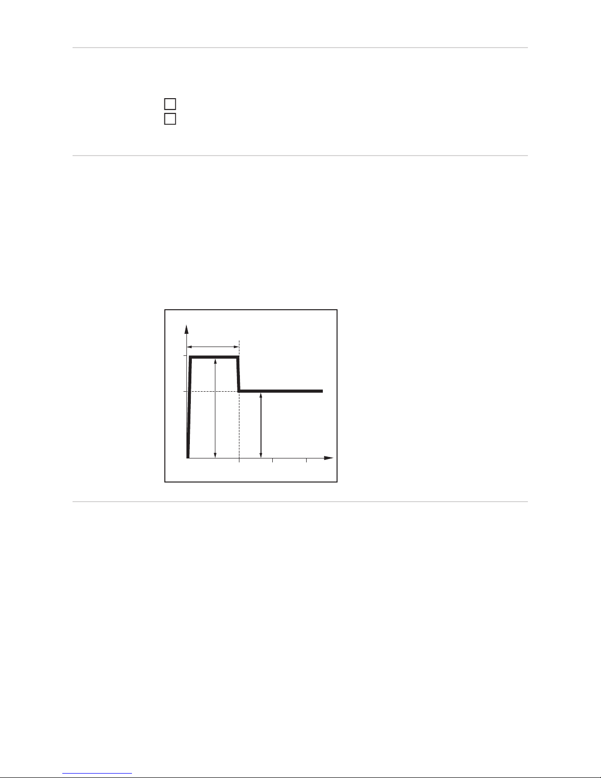
74
Corrections during welding
To obtain the best possible welding results, the arc-force dynamic parameter will sometimes need to be adjusted.
Press the "Parameter selection" button to select the arc-force dynamic parameter
Use the adjusting dial to set the desired arc-force dynamic value
The welding parameter value is shown in the digital display located above it.
HotStart function To obtain optimum welding results, it will sometimes be necessary to adjust the HotStart
function.
Advantages
- Improved ignition, even when using electrodes with poor ignition properties
- Better fusion of the base material during the start-up phase, meaning fewer cold-shut
defects
- Largely prevents slag inclusions
For details on setting the available welding parameters, please refer to "Setup parameters", "Setup menu - level 2".
Legend
Hti: Hot-current time,
0 - 2 s, factory setting: 0.5 s
HCU: HotStart-current,
100 - 200 %, factory setting 150 %
IH: Main current = set welding current
Function
During the specified hot-current time (Hti),
the welding current is increased to a certain
value. This value (HCU) is higher than the
selected welding current (IH).
Anti-stick function
As the arc becomes shorter, the welding voltage may drop so far that the rod electrode will
tend to "stick". This may also cause "burn-out" of the rod electrode.
Electrode burn-out is prevented by activating the anti-stick function. If the rod electrode begins to stick, the power source immediately switches the welding current off. After the rod
electrode has been detached from the workpiece, the welding operation can be continued
without difficulty.
The anti-stick (Ast) function can be activated and deactivated in the Setup parameters in
"Setup menu: level 2".
1
2
200
300
I (A)
Hti
HCU > I
H
t (s)
I
H
HCU
0,5 1 1,5
Page 75
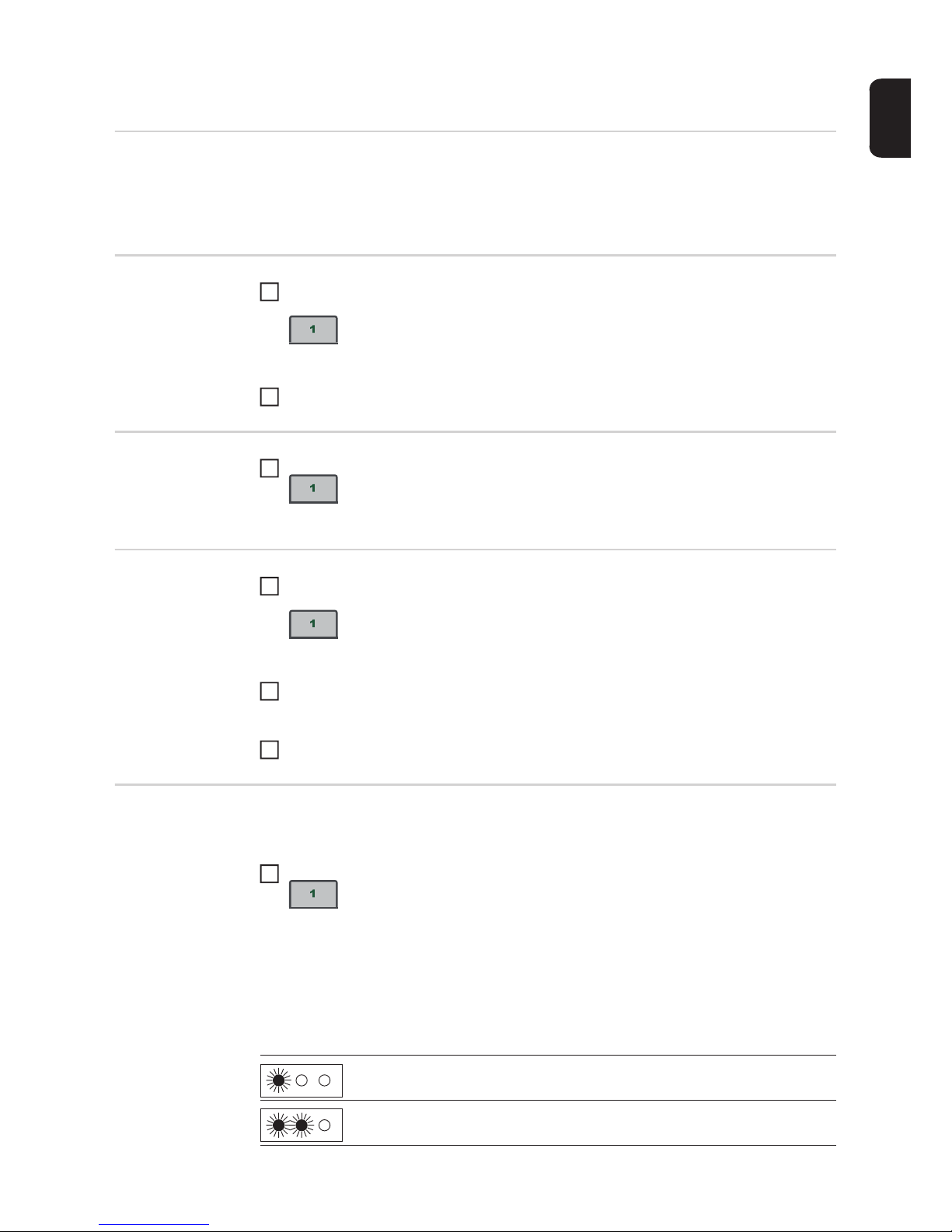
75
EN
Saving and retrieving operating points
General The "Save" buttons allow up to 5 operating points to be saved. Every operating point
matches the settings on the control panel.
IMPORTANT! Setup parameters are not saved at this time.
Saving operating
points
Press and hold one of the "Save" buttons to save the current settings on the control
panel, e.g.:
- The left indicator displays "Pro"
- After a short time, the left indicator switches to the original value
Release the "Save" button
Retrieving operating points
To retrieve saved settings, press the corresponding "Save" button briefly, e.g.:
- The control panel will show the saved settings
Deleting operating points
Press and hold the relevant "Save" button to delete the memory content of that "Save"
button, e.g.:
- The left indicator displays "Pro"
- After a short time, the left indicator switches to the original value
Keep the "Save" button held down
- The left display shows "CLr".
- After a while, both displays show "---"
Release the "Save" button
Retrieving operating points on the
Up/Down welding
torch
One of the "Save" buttons on the control panel must be pressed to retrieve the saved settings using the Up/Down welding torch.
Press one of the "Save" buttons on the control panel, e.g.:
- The control panel will show the saved settings
The "Save" buttons can now be selected using the buttons on the Up/Down welding torch.
Vacant "Save" buttons are skipped.
In addition to the "Save" button number lighting up, a number is displayed directly on the
Up/Down welding torch:
1
2
1
1
2
3
Number 1
Number 2
1
Page 76

76
Number 3
Number 4
Number 5
Page 77

Setup settings
Page 78

Page 79
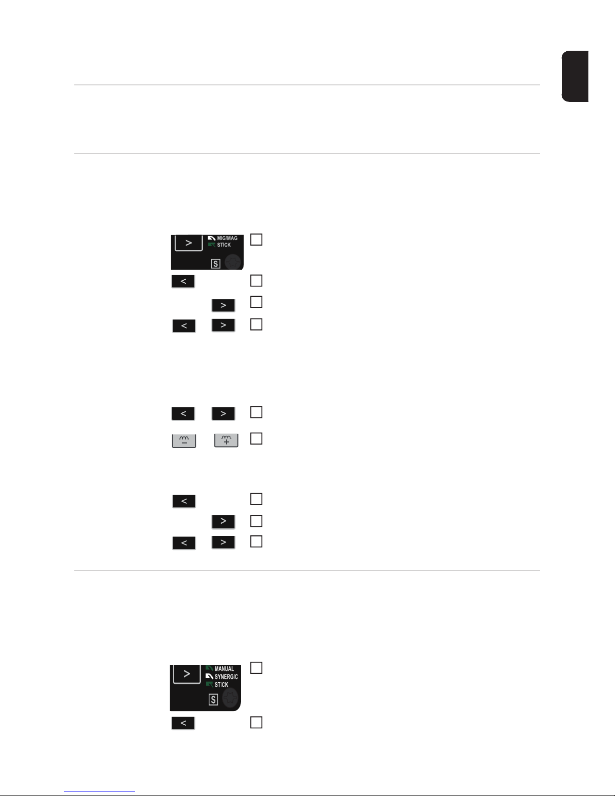
79
EN
Setup menu
General remarks The Setup menu provides simple access to expert knowledge in the power source and to
additional functions. The Setup menu can be used to make simple adjustments of the parameters to suit the various job settings.
Setup menu manual control
panel
Setting the setup parameters is described here with reference to the "MIG/MAG welding"
process. The procedure for changing other setup parameters is identical.
Accessing the setup menu
The control panel is now in the setup menu for the "MIG/MAG welding" process - the last
setup parameter that was selected is displayed.
Changing welding parameters
Exiting the setup menu
Setup menu Synergic A control panel
Setting the setup parameters is described here with reference to the "MIG/MAG standard
synergic welding" process. The procedure for changing other setup parameters is identical.
Accessing the setup menu
Use the "Process" button to select the "MIG/MAG welding" process
Press the "Mode" button
Press the "Process" button
Release the "Mode" and "Process" buttons
Use the "Mode" and "Process" buttons to select the required setup parameter
Use the "Dynamic" buttons to change the value of the setup parameter
Press and hold the "Mode" button
Press the "Process" button
Release the "Mode" and "Process" buttons
1
2
3
4
5
6
7
8
9
Use the "Process" button to select the "MIG/MAG standard synergic welding" process
Press and hold the "Mode" button
1
2
Page 80
80
The control panel is now in the setup menu for the "MIG/MAG standard synergic welding"
process - the last setup parameter that was selected is displayed.
Changing welding parameters
Exiting the setup menu
Press the "Process" button
Release the "Mode" and "Process" buttons
Use the "Mode" and "Process" buttons or the left-hand adjusting
dial to select the required setup parameter
3
4
5
Use the "Parameter selection" buttons or the right-hand adjusting
dial to change the value of the setup parameter
6
Press and hold the "Mode" button
Press the "Process" button
Release the "Mode" and "Process" buttons
7
8
9
Page 81

81
EN
Setup parameters
for MIG/MAG
standard manual
welding
"Min." and "max." are used for setting ranges that differ according to power source, wirefeed unit, welding program, etc.
GPr Gas pre-flow time
Unit: s
Setting range: 0 - 9.9
Factory setting: 0.5
GPo Gas post-flow time
Unit: s
Setting range: 0 - 9.9
Factory setting: 0.5
Fdi Feeder inching (speed)
Unit: m/min (ipm.)
Setting range: 1 - max. (39.37 - max.)
Factory setting: 10 (393.7)
SL Slope (special 4-step mode only)
Unit: s
Setting range: 0 - 9.9
Factory setting: 0.1
I-S I (current) - Starting - Starting current (special 4-step mode only)
Unit: % (of welding current)
Setting range: 0 - 200
Factory setting: 100
I-E I (current) - End: Final current (special 4-step mode only)
Unit: % (of welding current)
Setting range: 0 - 200
Factory setting: 50
t-S t (time) - Starting - Starting current duration (special 4-step mode only)
Unit: s
Setting range: OFF, 0.1 - 9.9
Factory setting: OFF
t-S t (time) - End: Final current duration (special 4-step mode only)
Unit: s
Setting range: OFF, 0.1 - 9.9
Factory setting: OFF
bbc burn-back time correction
Unit: ms
Setting range: 0 - 20
Factory setting: 0
IGC Ignition current
Unit: A
Setting range: 100 - 650
Factory setting: 500
Ito Ignition time-out function - Length of wire that is fed before the safety cut-out
is triggered
Unit: mm (in.)
Setting range: Off, 5 - 100 (Off, 0.2 - 3.94)
Page 82

82
Factory setting: Off
NOTE!
The "Ignition time-out" function (ito) is a safety function.
The length of wire that is fed before the safety cut-out trips may differ from the preset wire
length, particularly when the wire is being fed at fast wire feed speeds.
The "Ignition time-out" function (ito) is explained in the "Special functions and options" section.
SPt Spot time - spot / stitch welding time
Unit: s
Setting range: OFF, 0.1 - 5
Factory setting: OFF
SPb Spot break - stitch pause time
Unit: s
Setting range: OFF, 0.1 - 10 (in 0.1 s increments)
Factory setting: OFF
FAC Factory - Reset power source to factory setting
Press and hold down the "Dynamic" (manual control panel) or "Parameter selection" (Synergic A control panel) button for 2 seconds to restore the factory settings.
When "PrG" is shown on the digital display, the power source has been reset.
IMPORTANT! When the power source is reset, all the personal settings in the Setup menu are lost. Operating points that were saved using the "Save" buttons are
retained when the power source is reset. The functions in the second level of the
Setup menu (2nd) are also not deleted. Exception: Ignition time-out function parameter (ito).
2nd Second level of the Setup menu (see "Setup menu - level 2")
Page 83
83
EN
Setup parameters
for MIG/MAG
standard synergic welding
"Min." and "max." are used for setting ranges that differ according to power source, wirefeed unit, welding program, etc.
GPr Gas pre-flow time
Unit: s
Setting range: 0 - 9.9
Factory setting: 0.1
GPo Gas post-flow time
Unit: s
Setting range: 0 - 9.9
Factory setting: 0.1
SL Slope
Unit: s
Setting range: 0 - 9.9
Factory setting: 0.1
I-S I (current) - Starting current
Unit: % (of welding current)
Setting range: 0 - 200
Factory setting: 100
I-E I (current) - End: Final current
Unit: % (of welding current)
Setting range: 0 - 200
Factory setting: 50
Fdi Feeder inching (speed)
Unit: m/min (ipm.)
Setting range: 1 - max. (39.37 - max.)
Factory setting: 10 (393.7)
bbc burn back time correction -
Burn back effect due to wire withdrawal at the end of welding
Unit: s
Setting range: Aut, 0 - 0.3
Factory setting: Aut
Ito Ignition time-out function - Length of wire that is fed before the safety cut-out
is triggered
Unit: mm (in.)
Setting range: Off, 5 - 100 (Off, 0.2 - 3.94)
Factory setting: Off
NOTE!
The "Ignition time-out" function (ito) is a safety function.
The length of wire that is fed before the safety cut-out trips may differ from the preset wire
length, particularly when the wire is being fed at fast wire feed speeds.
Page 84

84
The "Ignition time-out" function (ito) is explained in the "Special functions and options" section.
SPt Spot time - spot / stitch welding time
Unit: s
Setting range: OFF, 0.1 - 5
Factory setting: OFF
SPb Spot break - stitch pause time
Unit: s
Setting range: OFF, 0.1 - 10 (in 0.1 s increments)
Factory setting: OFF
FAC Factory - Reset power source to factory setting
Press and hold down the "Dynamic" (manual control panel) or "Parameter selection" (Synergic A control panel) button for 2 seconds to restore the factory settings.
When "PrG" is shown on the digital display, the power source has been reset.
IMPORTANT! When the power source is reset, all the personal settings in the Setup menu are lost. When the power source is reset, operating points that were
saved using the "Save" buttons are not deleted, but are retained in the memory.
The functions in the second level of the Setup menu (2nd) are also not deleted. Exception: Ignition time-out function parameter (ito).
2nd Second level of the Setup menu (see "Setup menu - level 2")
Setup parameters
for MMA welding
IMPORTANT! If you reset the power source using the FAC factory setup parameter, the
hot-current time (Hti) and HotStart current (HCU) setup parameters are also reset.
HCU HotStart current
Unit: %
Setting range: 100 - 200
Factory setting: 150
Hti Hot-current time
Unit: s
Setting range: 0 - 2.0
Factory setting: 0.5
Ast Anti-Stick
Unit: Setting range: On, Off
Factory setting: Off
FAC Factory - Reset power source to factory setting
Press and hold down the "Dynamic" (manual control panel) or "Parameter selection" (Synergic A control panel) button for 2 seconds to restore the factory settings.
When "PrG" is shown on the digital display, the power source has been reset.
IMPORTANT! When the power source is reset, all personal settings are lost.
When the power source is reset, operating points that were saved using the "Save"
buttons are not deleted, but are retained in the memory. The functions in the second level of the Setup menu (2nd) are also not deleted. Exception: Ignition timeout function parameter (ito).
2nd Second level of the Setup menu (see "Setup menu - level 2")
Page 85

85
EN
Welding parameters for "Special
4-step mode" in
the Mode setup
menu
I-S I (current) - Starting: Starting current
Unit: % (of welding current)
Setting range: 0 - 200
Factory setting: 100
SL Slope: 0 - 9.9 s
Unit: s
Setting range: 0 - 9.9
Factory setting: 0
I-E I (current) - End: Final current
Unit: % of welding current
Setting range: 0 - 200
Factory setting: 50
Page 86
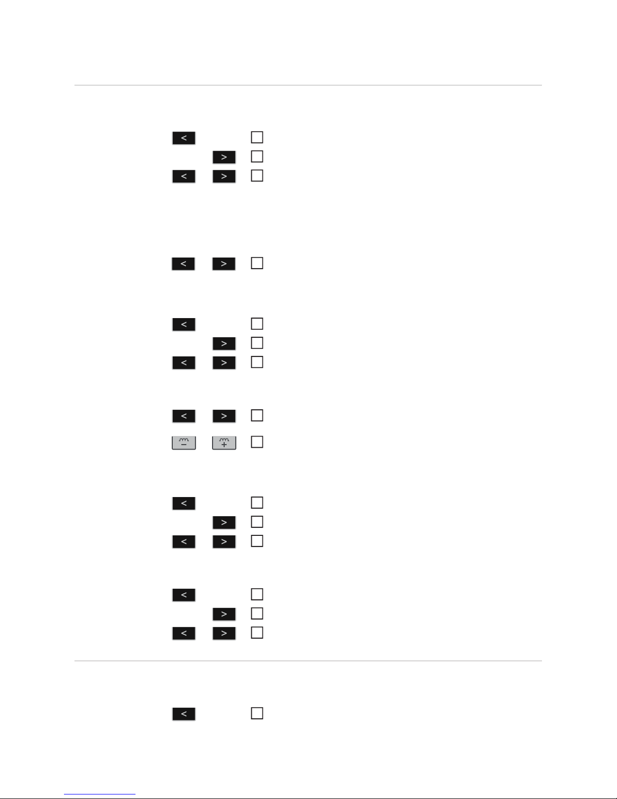
86
Setup menu - Level 2
Level 2 setup
menu - manual
control panel
Accessing the setup menu
The control panel is now in the setup menu - the last setup parameter that was selected is
displayed.
Selecting the "2nd" parameter
Accessing the Level 2 setup menu
Changing welding parameters
Exiting the Level 2 setup menu
Exiting the setup menu
Level 2 setup
menu - Synergic
control panel
Accessing the setup menu
Press and hold the "Mode" button
Press the "Process" button
Release the "Mode" and "Process" buttons
Use the "Mode" and "Process" buttons to select the "2nd" setup
parameter
Press and hold the "Mode" button
Press the "Process" button
Release the "Mode" and "Process" buttons
Use the "Mode" and "Process" buttons to select the required setup parameter
Use the "Dynamic" buttons to change the value of the setup parameter
Press and hold the "Mode" button
Press the "Process" button
Release the "Mode" and "Process" buttons
Press and hold the "Mode" button
Press the "Process" button
Release the "Mode" and "Process" buttons
1
2
3
4
5
6
7
8
9
10
11
12
13
14
15
Press and hold the "Mode" button
1
Page 87
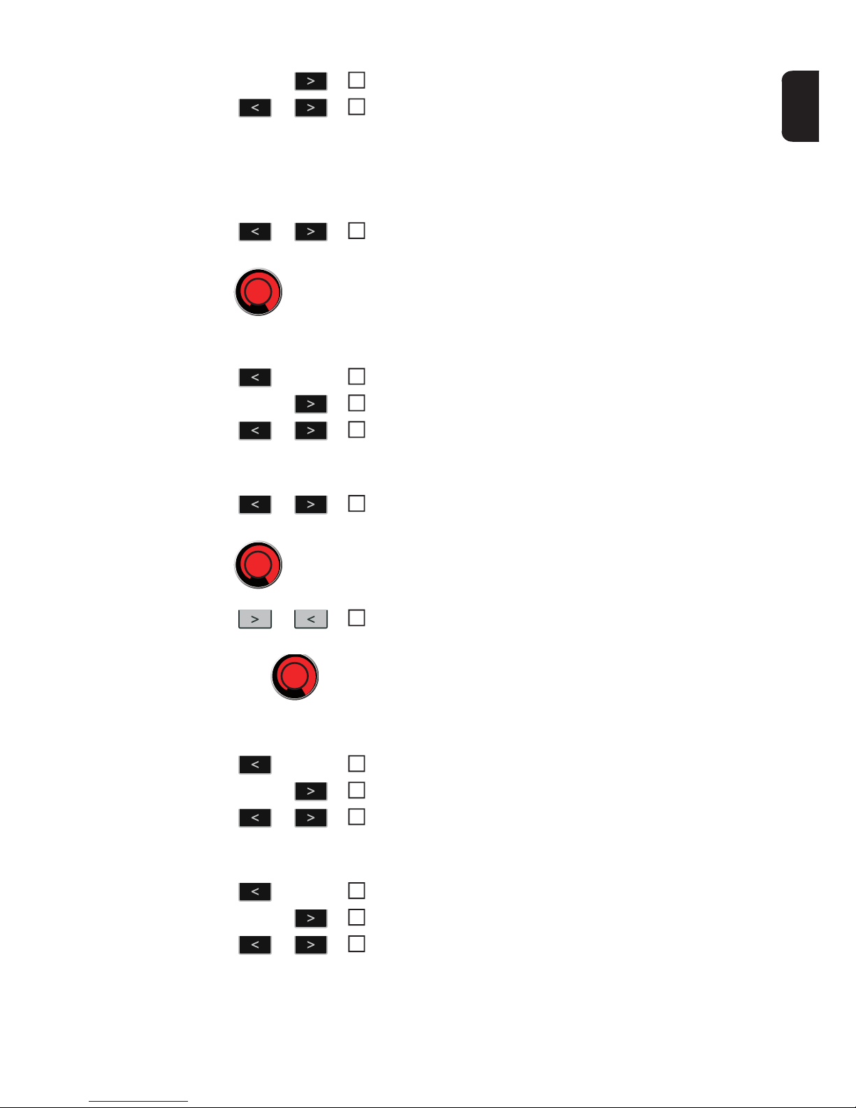
87
EN
The control panel is now in the setup menu - the last setup parameter that was selected is
displayed.
Selecting the "2nd" parameter
Accessing the Level 2 setup menu
Changing welding parameters
Exiting the Level 2 setup menu
Exiting the setup menu
Press the "Process" button
Release the "Mode" and "Process" buttons
Use the "Mode" and "Process" buttons or the left-hand adjusting
dial to select the "2nd" setup parameter
2
3
4
Press and hold the "Mode" button
Press the "Process" button
Release the "Mode" and "Process" buttons
Use the "Mode" and "Process" buttons or the left-hand adjusting
dial to select the required setup parameter
5
6
7
8
Use the "Parameter selection" buttons or the right-hand adjusting
dial to change the value of the setup parameter
9
Press and hold the "Mode" button
Press the "Process" button
Release the "Mode" and "Process" buttons
Press and hold the "Mode" button
Press the "Process" button
Release the "Mode" and "Process" buttons
10
11
12
13
14
15
Page 88

88
Welding parameters for MIG/MAG
welding in the
Setup menu level
2
C-C Cooling unit control
Unit: Setting range: Aut, On, Off
Factory setting: Aut
Aut: The cooling unit cuts out after a 2-minute welding off-time.
IMPORTANT! If the coolant temperature and flow monitoring options have been
installed in the cooling unit, the cooling unit cuts out as soon as the return-flow
temperature drops below 50°C, but at the earliest after a 2-minute welding offtime.
On: The cooling unit is permanently ON
Off: The cooling unit is permanently OFF
IMPORTANT! If the FAC welding parameter is used, the C-C parameter is not
restored to the factory setting. If the MMA welding process is selected, the cooling unit is always switched off, even if the switch is in the "On" position.
C-t Cooling time - time from when flow monitoring is triggered until the "no | H2O"
service code is output. For example, if there are air bubbles in the cooling system, the cooling unit will not cut out until the end of this pre-set time.
Unit: s
Setting range: 5 - 25
Factory setting: 10
IMPORTANT! Every time the power source is switched on, the cooling unit carries out a test run for 180 seconds.
SEt Setting - country-specific setting (Standard/USA) ... Std / US
Unit: Setting range: Std, US (Standard/USA)
Factory setting:
Standard version: Std (measurements: cm/mm)
USA version: US (measurements: inches)
r r (resistance) - welding circuit resistance (in mOhm)
see "Measuring welding circuit resistance r"
L L (inductivity) - welding circuit inductivity (in microhenry)
see "Displaying welding circuit inductivity L"
EnE Real Energy Input – electrical energy of the arc relative to the welding speed
Unit: kJ
Setting range: ON / OFF
Factory setting: OFF
Since the full range of values (1 kJ - 99999 kJ) cannot be displayed on the threedigit display, the following display format has been selected:
Value in kJ / indication on display:
1 to 999 / 1 to 999
1000 to 9999 / 1.00 to 9.99 (without "ones" digit, e.g. 5270 kJ -> 5.27)
10000 to 99999 / 10.0 to 99.9
(without "ones" and "tens" digits, e.g. 23580 kJ -> 23.6)
Page 89

89
EN
Parameters for
manual metal arc
(MMA) welding in
the Setup menu
level 2
PFS Permanent Feeder Speed - wire feed speed is permanently displayed
Unit: mm (in.)
Setting range: ON / OFF
Factory setting: OFF
If the setting is "ON", the wire feed speed (m/min) is permanently displayed on
the manual control panel instead of the welding current (A). In this case the hold
value for the welding current (A) is deactivated.
ALC Arc Length Correction - correction of the arc length via the welding voltage
Setting range: ON / OFF
Factory setting: OFF
The arc length depends on the welding voltage. The welding voltage can be adjusted to suit individual needs in Synergic operation.
If the ALC parameter is set to "OFF", the welding voltage cannot be adjusted.
The welding voltage is automatically determined by the selected welding current
or wire speed. If the arc length correction is adjusted, the voltage changes, but
the welding current and wire speed remain the same. When setting the arc length
correction using the adjusting dial, the left display is used for the correction value
of the arc length. The welding voltage value on the right display changes simultaneously. Afterwards the left display shows the original value, e.g. welding current.
r r (resistance) - welding circuit resistance (in mOhm)
see "Measuring welding circuit resistance r"
L L (inductivity) - welding circuit inductivity (in microhenry)
see "Displaying welding circuit inductivity L"
Page 90
90
Measuring welding circuit resistance r
General Measuring the welding circuit resistance r makes it possible to have a constant welding re-
sult at all times, even with hosepacks of different lengths. The welding voltage at the arc is
then always precisely regulated, regardless of the length and cross-sectional area of the
hosepack. The use of arc length correction is no longer required.
The calculated welding circuit resistance is shown on the display.
r = welding circuit resistance in milliohm (mOhm)
If the welding circuit resistance r has been measured correctly, the set welding voltage will
correspond exactly to the welding voltage at the arc. If you manually measure the voltage
on the output jacks of the power source, this voltage will be higher than the welding voltage
at the arc - that is, higher by the same amount as the voltage drop of the hosepack.
NOTE!
The welding circuit resistance r depends on the hosepack used:
► If the length or cross-sectional area of the hosepack has changed, measure the weld-
ing circuit resistance r again
► Measure the welding circuit resistance for every welding process separately with the
appropriate welding power-leads
Measure the
welding circuit resistance r
NOTE!
In order to obtain good welding results, it is essential to measure the welding circuit
resistance correctly.
Make sure that the contact between the earthing clamp and the workpiece is on a cleaned
workpiece surface.
Establish a grounding (earthing) connection to the workpiece
Accessing the Level 2 (2nd) Setup menu
Select parameter "r"
Remove the gas nozzle from the welding torch
Screw on the contact tip
NOTE!
Make sure that the contact between the contact tip and the workpiece is on a cleaned
workpiece surface.
Place the contact tip flush against the workpiece surface
Press the torch trigger briefly
- The welding circuit resistance is calculated. "run" is shown on the display during
the measurement
The measurement is finished when the welding circuit resistance is shown on the display
in mOhm ( for example, 11.4).
Fit the gas nozzle back onto the welding torch
1
2
3
4
5
6
7
8
Page 91
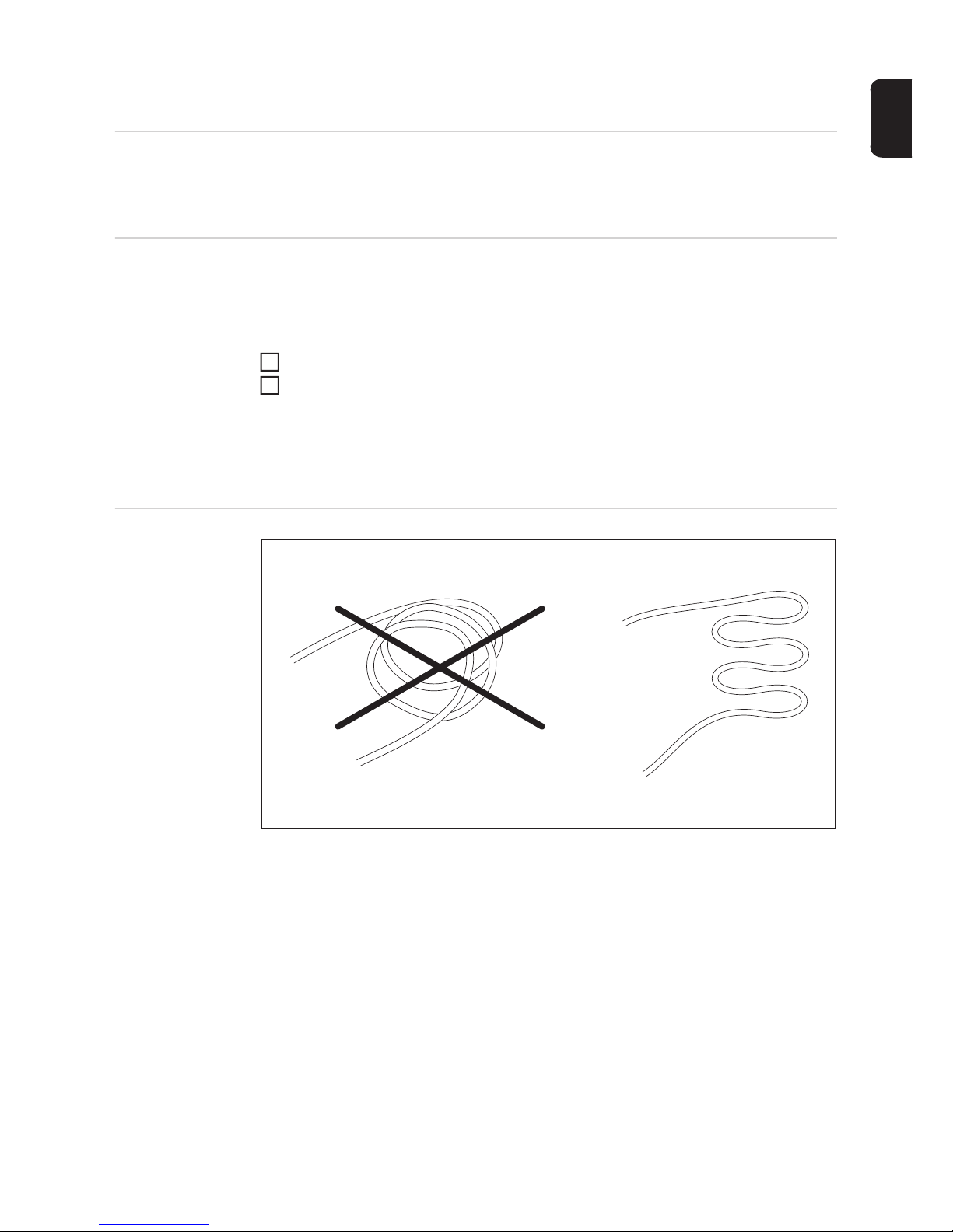
91
EN
Displaying welding circuit inductivity L
General Laying of the hosepacks has a significant effect on welding circuit inductivity and therefore
affects the welding process. It is important to lay the hosepacks correctly in order to obtain
the best possible welding result.
Displaying welding circuit inductivity L
The setup parameter "L" is used to display the most recently calculated welding circuit inductivity. The welding circuit inductivity is calibrated at the same time as the welding circuit
resistance r is calculated. Detailed information can be found in the "Measuring welding circuit resistance r" section.
Access the setup menu level 2 (2nd)
Select parameter “L”
The most recently calculated welding circuit inductivity L is shown on the right-hand digital
display.
L ... Welding circuit inductivity (in microhenry)
Laying the hosepacks correctly
1
2
Page 92

92
Page 93

Troubleshooting and maintenance
Page 94

Page 95
95
EN
Troubleshooting
General The devices are equipped with an intelligent safety system. This means that to a large ex-
tent it has been possible to dispense with melting-type fuses. Melting-type fuses therefore
no longer need to be replaced. After a possible malfunction has been remedied, the device
is ready for use again.
Safety
WARNING!
Work that is carried out incorrectly can cause serious injury or damage.
The following activities must only be carried out by trained and qualified personnel. Read
the safety rules in the wire-feed unit operating instructions.
WARNING!
An electric shock can be fatal.
Before opening the unit
► Turn the mains switch to the "O" position
► Unplug the device from the mains
► Put up an easy-to-understand warning sign to stop anybody inadvertently switching it
back on again
► Using a suitable measuring device, check to make sure that electrically charged com-
ponents (e.g. capacitors) have discharged
CAUTION!
Inadequate PE conductor connections can cause serious injury and damage.
The housing screws provide a suitable PE conductor connection for earthing (grounding)
the housing and must NOT be replaced by any other screws which do not provide a reliable
PE conductor connection.
Fault diagnosis Make a note of the serial number and configuration of the device and contact our After-
Sales Service team with a detailed description of the error, if
- errors occur that are not listed below
- the troubleshooting measures listed are unsuccessful
Power source has no function
Mains switch is on, but indicators are not lit up
Cause: There is a break in the mains lead; the mains plug is not plugged in
Remedy: Check the mains lead, ensure that the mains plug is plugged in
Cause: Mains socket or mains plug faulty
Remedy: Replace faulty parts
Cause: Mains fuse protection
Remedy: Change the mains fuse protection
Page 96

96
Nothing happens when the torch trigger is pressed
Power source mains switch is ON and indicators are lit up
Cause: Only for welding torches with an external control plug: The control plug is not
plugged in
Remedy: Plug in the control plug
Cause: Welding torch or welding torch control line is faulty
Remedy: Replace welding torch
Nothing happens when the torch trigger is pressed
Power source mains switch is on, power source ON indication is lit up on the power source,
indications on wire-feed unit are not lit up
Cause: The interconnecting hosepack is faulty or not connected properly
Remedy: Check interconnecting hosepack
No welding current
Mains switch is on, one of the overtemperature service codes "to" is displayed. Detailed
information on the service codes "to0" to "to6" can be found in the section "Displayed service codes".
Cause: Overload
Remedy: Take the duty cycle into account
Cause: Thermostatic safety cut-out has tripped
Remedy: Wait until the power source automatically comes back on after the end of the
cooling phase
Cause: Limited supply of cooling air
Remedy: Remove air filter on the rear of the housing from the side and clean. Ensure
that the cooling air ducts are accessible.
Cause: The fan in the power source is faulty
Remedy: Contact After-Sales Service
No welding current
Mains switch is ON and indicators are lit up
Cause: Grounding (earthing) connection is incorrect
Remedy: Check the grounding (earthing) connection for correct polarity
Cause: There is a break in the power cable in the welding torch
Remedy: Replace the welding torch
Page 97

97
EN
No protective gas shield
All other functions are OK
Cause: Gas cylinder is empty
Remedy: Change the gas cylinder
Cause: The gas pressure regulator is faulty
Remedy: Replace the gas pressure regulator
Cause: Gas hose is not fitted or is damaged
Remedy: Fit or change the gas hose
Cause: Welding torch is faulty
Remedy: Change the welding torch
Cause: Gas solenoid valve is faulty
Remedy: Contact After-Sales Service
Irregular wire feed speed
Cause: Braking force has been set too high
Remedy: Loosen the brake
Cause: Hole in the contact tip is too narrow
Remedy: Use a suitable contact tip
Cause: Faulty inner liner in welding torch
Remedy: Check the inner liner for kinks, dirt, etc. and replace if necessary
Cause: The feed rollers are not suitable for the wire electrode being used
Remedy: Use suitable feed rollers
Cause: Feed rollers have the wrong contact pressure
Remedy: Optimise the contact pressure
Wirefeed problems
when using long hosepacks
Cause: Incorrect arrangement of hosepack
Remedy: Arrange the hosepack in as straight a line as possible, avoid tight bends
Welding torch becomes very hot
Cause: The specification of the welding torch is inadequate
Remedy: Observe the duty cycle and loading limits
Cause: Only on water-cooled systems: Inadequate coolant flow
Remedy: Check coolant level, coolant flow, for coolant contamination, etc. For further
information refer to the cooling unit operating instructions.
Page 98

98
Poor weld properties
Cause: Incorrect welding parameters
Remedy: Check the settings
Cause: Poor ground earth connection
Remedy: Ensure good contact to workpiece
Cause: Inadequate or no protective gas shield
Remedy: Check the pressure regulator, gas hose, gas solenoid valve, torch gas con-
nection, etc.
Cause: Welding torch is leaking
Remedy: Change the welding torch
Cause: Wrong contact tip, or contact tip is worn out
Remedy: Replace the contact tip
Cause: Wrong wire alloy or wrong wire diameter
Remedy: Check the wire electrode that has been inserted
Cause: Wrong wire alloy or wrong wire diameter
Remedy: Check weldability of the base material
Cause: The shielding gas is not suitable for this wire alloy
Remedy: Use the correct shielding gas
Displayed service
codes
If an error message that is not described here appears on the displays, proceed as follows
to resolve the problem:
Turn the power source mains switch to the "O" position
Wait 10 seconds
Move the mains switch to the I position
If the error occurs again despite several attempts to eliminate it, or if the troubleshooting
measures listed here are unsuccessful.
Make a note of the error message displayed
Note down the configuration of the power source
Contact our After-Sales Service team with a detailed description of the error
ESr | 20
Cause: The selected cooling unit is not compatible with the power source
Remedy: Connect compatible cooling unit
-----
Cause: An invalid welding process was called up on the robot interface (no. 37) or an
empty flag was selected (no. 32)
Remedy: Call up a valid welding process or select assigned "Save" button
1
2
3
1
2
3
Page 99

99
EN
ELn | 8
Cause: The connected wire-feed unit is not supported
Remedy: Connect supported wire-feed unit
ELn | 12
Cause: Different control panels for selecting materials are in the system
Remedy: Connect similar control panels to select materials
ELn | 13
Cause: Invalid change of welding process during welding
Remedy: During welding do not carry out any illegal change of the welding process, re-
set error message by pressing any button
ELn | 14
Cause: More than only one robot interface is connected
Remedy: Only one robot interface may be connected, check the system configuration
ELn | 15
Cause: More than only one remote control unit is connected
Remedy: Only one remote control unit may be connected, check the system configura-
tion
Err | IP
Cause: The control unit of the power source has detected a primary overvoltage
Remedy: Check mains voltage, if the service code still remains, switch off the power
source, wait for 10 seconds and then switch the power source on again, if the
error keeps recurring, contact After-Sales Service
Err | PE
Cause: The earth current watchdog has triggered the safety cut-out of the power
source.
Remedy: Switch off the power source
Place the power source on an insulating surface
Connect the grounding (earthing) cable to a section of the workpiece that is
closer to the arc
Wait for 10 seconds and then switch the power source on again
If you have tried this several times and the error keeps recurring, contact After-Sales Service
Err | Ur
Cause: If the VRD option is available, the open circuit voltage limit of 35 V has been
exceeded.
Remedy: Switch off power source
Wait for 10 seconds and then switch the power source on again
no | UrL
Cause: The VRD option has tripped too early.
Remedy: Check whether all welding power-leads and control lines are connected.
Switch off the power source
Wait 10 seconds and switch the power source back on again
If the error occurs again - contact After Sales Service.
Page 100

100
E-Stop
Cause: "External stop" has tripped
Remedy: Remedy the event that triggered the external stop
-St | oP-
Cause: At the robot interface the flag was not deleted by the robot
Remedy: Delete the signal robot ready at the robot interface
PHA | SE
Cause: Phase failure
Remedy: Check the mains fuse, the mains lead and the mains plug
PHA | SE1
Cause: The power source is operated in single-phase mode.
Remedy: -
PHA | SE3
Cause: The power source is operated in 3-phase mode
Remedy: -
Err | 51
Cause: Mains undervoltage: The mains voltage has fallen below the tolerance range
Remedy: Check the mains voltage, if the error keeps recurring, contact the After-Sales
Service
Err | 52
Cause: Mains overvoltage: The mains voltage has risen above the tolerance range
Remedy: Check the mains voltage, if the error keeps recurring, contact the After-Sales
Service
EFd 5
Cause: Incorrect wire-feed unit connected
Remedy: Connect correct wire-feed unit
EFd 8
Cause: Overtemperature on the wire-feed unit
Remedy: Allow wire-feed unit to cool down
EFd | 81, EFd | 83
Cause: Fault in the wire feed system (overcurrent in wire-feed unit drive)
Remedy: Arrange the hosepack in as straight a line as possible; check that there are
no kinks or dirt in the inner liner; check the contact pressure on the 4 roller
drive
Cause: Wire-feed unit motor is sticking or defective
Remedy: Check the wire-feed unit motor or contact After-Sales Service
to0 | xxx
Note: xxx stands for a temperature value
Cause: Overtemperature in the primary circuit of the power source
Remedy: Allow power source to cool down, check air filter and clean if necessary,
check that fan is on
 Loading...