

Page 1
Fronius prints on elemental chlorine free paper (ECF) sourced from certified sustainable forests (FSC).
/ Perfect Charging / Perfect Welding / Solar Energy
VR 1500-M
Operating Instructions
EN
Wire-feed unit
[
42,0426,0008,EN 001-05022020
Page 2

2
Page 3
Dear reader,
Introduction Thank you for the trust you have placed in our company and congratulations on buying this
high-quality Fronius product. These instructions will help you familiarise yourself with the
product. Reading the instructions carefully will enable you to learn about the many different
features it has to offer. This will allow you to make full use of its advantages.
Please also note the safety rules to ensure greater safety when using the product. Careful
handling of the product will repay you with years of safe and reliable operation. These are
essential prerequisites for excellent results.
EN
Explanation of
safety notices
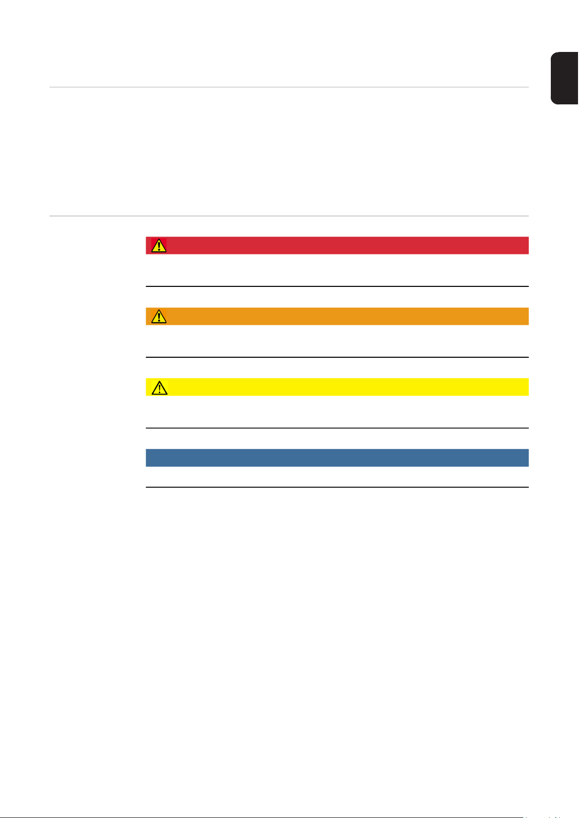
DANGER!
Indicates immediate danger.
► If not avoided, death or serious injury will result.
WARNING!
Indicates a potentially hazardous situation.
► If not avoided, death or serious injury may result.
CAUTION!
Indicates a situation where damage or injury could occur.
► If not avoided, minor injury and/or damage to property may result.
NOTE!
Indicates a risk of flawed results and possible damage to the equipment.
3
Page 4

4
Page 5

Contents
Safety rules ................................................................................................................................................ 7
General ................................................................................................................................................. 7
Proper use ............................................................................................................................................ 7
Environmental conditions...................................................................................................................... 7
Obligations of the operator.................................................................................................................... 8
Obligations of personnel ....................................................................................................................... 8
Mains connection .................................................................................................................................. 8
Protecting yourself and others .............................................................................................................. 8
Danger from toxic gases and vapours .................................................................................................. 9
Danger from flying sparks ..................................................................................................................... 10
Risks from mains current and welding current...................................................................................... 10
Meandering welding currents................................................................................................................ 11
EMC Device Classifications .................................................................................................................. 11
EMC measures ..................................................................................................................................... 11
EMF measures...................................................................................................................................... 12
Specific hazards.................................................................................................................................... 12
Requirement for the shielding gas ........................................................................................................ 13
Danger from shielding gas cylinders..................................................................................................... 13
Danger from escaping shielding gas..................................................................................................... 14
Safety measures at the installation location and during transport ........................................................ 14
Safety measures in normal operation ................................................................................................... 15
Commissioning, maintenance and repair.............................................................................................. 15
Safety inspection................................................................................................................................... 16
Disposal ................................................................................................................................................ 16
Safety symbols...................................................................................................................................... 16
Data protection...................................................................................................................................... 16
Copyright............................................................................................................................................... 16
General ...................................................................................................................................................... 17
Device concept ..................................................................................................................................... 17
Preconditions for use ............................................................................................................................ 17
Applications........................................................................................................................................... 17
Scope of delivery .................................................................................................................................. 18
Additional requirements ........................................................................................................................ 19
Warning notices on the device................................................................................................................... 20
General ................................................................................................................................................. 20
Controller .............................................................................................................................................. 20
Drive plate............................................................................................................................................. 21
Options....................................................................................................................................................... 22
Wire feeder hose .................................................................................................................................. 22
Lockable pressure lever for drive plate ................................................................................................. 22
Wire end plug kit ................................................................................................................................... 22
Wire coil intake robot, cover for wire coil intake robot........................................................................... 22
Wire end sensors .................................................................................................................................. 22
Controls, connections and mechanical components.................................................................................. 23
General ................................................................................................................................................. 23
Controller .............................................................................................................................................. 23
Drive plate............................................................................................................................................. 24
Assembly - overview .................................................................................................................................. 25
Safety.................................................................................................................................................... 25
Assembly: Overview ............................................................................................................................. 25
Attaching the VR 1500 M to the robot........................................................................................................ 26
Preparation ........................................................................................................................................... 26
Attaching the VR 1500 M to the robot................................................................................................... 26
Attaching the welding torch to the drive plate ....................................................................................... 28
Attaching the welding torch to the drive plate ....................................................................................... 29
Attaching the controller to the power source......................................................................................... 29
Calibrating the drive plate and controller ................................................................................................... 30
General ................................................................................................................................................. 30
Calibrating the drive plate and controller .............................................................................................. 30
Inserting/replacing feed rollers................................................................................................................... 32
EN
5
Page 6

General remarks ................................................................................................................................... 32
USA wirefeeders ................................................................................................................................... 32
inserting/replacing feed rollers .............................................................................................................. 32
Feeding in the wire electrode..................................................................................................................... 33
Insulated routing of wire electrode to wire-feed unit ............................................................................. 33
Feeding in the wire electrode................................................................................................................ 33
Set the contact pressure ....................................................................................................................... 35
Care, maintenance and disposal ............................................................................................................... 36
General remarks ................................................................................................................................... 36
Every start-up........................................................................................................................................ 36
Every 6 months ..................................................................................................................................... 36
Disposal ................................................................................................................................................ 36
Troubleshooting ......................................................................................................................................... 37
"Wire end" error message..................................................................................................................... 37
"Wire end" special function ................................................................................................................... 37
Troubleshooting .................................................................................................................................... 37
Error reset ............................................................................................................................................. 37
Technical data............................................................................................................................................ 38
VR 1500-M............................................................................................................................................ 38
6
Page 7

Safety rules
General The device is manufactured using state-of-the-art technology and according to recognised
safety standards. If used incorrectly or misused, however, it can cause:
- injury or death to the operator or a third party,
- damage to the device and other material assets belonging to the operating company,
- inefficient operation of the device.
All persons involved in commissioning, operating, maintaining and servicing the device
must:
- be suitably qualified,
- have sufficient knowledge of welding and
- read and follow these operating instructions carefully.
The operating instructions must always be at hand wherever the device is being used. In
addition to the operating instructions, attention must also be paid to any generally applicable and local regulations regarding accident prevention and environmental protection.
All safety and danger notices on the device
- must be in a legible state,
- must not be damaged,
- must not be removed,
- must not be covered, pasted or painted over.
EN
For the location of the safety and danger notices on the device, refer to the section headed
"General" in the operating instructions for the device.
Before switching on the device, rectify any faults that could compromise safety.
This is for your personal safety!
Proper use The device is to be used exclusively for its intended purpose.
The device is intended solely for the welding processes specified on the rating plate.
Any use above and beyond this purpose is deemed improper. The manufacturer shall not
be held liable for any damage arising from such usage.
Proper use includes:
- carefully reading and following all the instructions given in the operating instructions
- studying and obeying all safety and danger notices carefully
- performing all stipulated inspection and maintenance work.
Never use the device for the following purposes:
- Thawing out pipes
- Charging batteries
- Starting engines
The device is designed for use in industry and the workshop. The manufacturer accepts
no responsibility for any damage caused through use in a domestic setting.
Environmental
conditions
The manufacturer likewise accepts no liability for inadequate or incorrect results.
Operation or storage of the device outside the stipulated area will be deemed as not in accordance with the intended purpose. The manufacturer shall not be held liable for any damage arising from such usage.
7
Page 8

Ambient temperature range:
- during operation: -10 °C to + 40 °C (14 °F to 104 °F)
- during transport and storage: -20 °C to +55 °C (-4 °F to 131 °F)
Relative humidity:
- up to 50% at 40 °C (104 °F)
- up to 90% at 20 °C (68 °F)
The surrounding air must be free from dust, acids, corrosive gases or substances, etc.
Can be used at altitudes of up to 2000 m (6561 ft. 8.16 in.)
Obligations of the
operator
The operator must only allow persons to work with the device who:
- are familiar with the fundamental instructions regarding safety at work and accident
prevention and have been instructed in how to use the device
- have read and understood these operating instructions, especially the section "safety
rules", and have confirmed as much with their signatures
- are trained to produce the required results.
Checks must be carried out at regular intervals to ensure that operators are working in a
safety-conscious manner.
Obligations of
personnel
Before using the device, all persons instructed to do so undertake:
- to observe the basic instructions regarding safety at work and accident prevention
- to read these operating instructions, especially the "Safety rules" section and sign to
confirm that they have understood them and will follow them.
Before leaving the workplace, ensure that people or property cannot come to any harm in
your absence.
Mains connection Devices with a higher rating may affect the energy quality of the mains due to their current
consumption.
Protecting yourself and others
This may affect a number device types in terms of:
- Connection restrictions
- Criteria with regard to the maximum permissible mains impedance
- Criteria with regard to the minimum short-circuit power requirement
*)
at the interface with the public grid
*)
*)
see "Technical data"
In this case, the plant operator or the person using the device should check whether the
device may be connected, where appropriate by discussing the matter with the power supply company.
IMPORTANT! Ensure that the mains connection is earthed properly
Anyone working with the device exposes themselves to numerous risks, e.g.
- flying sparks and hot pieces of metal
- Arc radiation, which can damage eyes and skin
- Hazardous electromagnetic fields, which can endanger the lives of those using cardiac pacemakers
- Risk of electrocution from mains current and welding current
- Greater noise pollution
- Harmful welding fumes and gases
8
Page 9

Suitable protective clothing must be worn when working with the device. The protective
clothing must have the following properties:
- Flame-resistant
- Insulating and dry
- Covers the whole body, is undamaged and in good condition
- Safety helmet
- Trousers with no turn-ups
Protective clothing refers to a variety of different items. Operators should:
- Protect eyes and face from UV rays, heat and sparks using a protective visor and regulation filter
- Wear regulation protective goggles with side protection behind the protective visor
- Wear stout footwear that provides insulation even in wet conditions
- Protect the hands with suitable gloves (electrically insulated and providing protection
against heat)
- Wear ear protection to reduce the harmful effects of noise and to prevent injury
Keep all persons, especially children, out of the working area while any devices are in operation or welding is in progress. If, however, there are people in the vicinity:
- Make them aware of all the dangers (risk of dazzling by the arc, injury from flying
sparks, harmful welding fumes, noise, possible risks from mains current and welding
current, etc.)
- Provide suitable protective equipment
- Alternatively, erect suitable safety screens/curtains.
EN
Danger from toxic
gases and vapours
The fumes produced during welding contain harmful gases and vapours.
Welding fumes contain substances that cause cancer, as stated in Monograph 118 of the
International Agency for Research on Cancer.
Use at-source extraction and a room extraction system.
If necessary, use a welding torch with an integrated extraction device.
Keep your face away from welding fumes and gases.
Fumes and hazardous gases
- must not be breathed in
- must be extracted from the working area using appropriate methods.
Ensure an adequate supply of fresh air. Ensure that there is a ventilation rate of at least
20 m³ per hour at all times.
Otherwise, a welding helmet with an air supply must be worn.
If there is any doubt about whether the extraction capacity is sufficient, the measured toxic
emission values should be compared with the permissible limit values.
The following components are responsible, amongst other things, for the degree of toxicity
of welding fumes:
- Metals used for the workpiece
- Electrodes
- Coatings
- Cleaners, degreasers, etc.
- Welding process used
The relevant material safety data sheets and manufacturer's specifications for the listed
components should therefore be studied carefully.
Recommendations for trade fair scenarios, risk management measures and for identifying
working conditions can be found on the European Welding Association website under
Health & Safety (https://european-welding.org).
9
Page 10

Flammable vapours (e.g. solvent fumes) should be kept away from the arc's radiation area.
Close the shielding gas cylinder valve or main gas supply if no welding is taking place.
Danger from flying sparks
Risks from mains
current and welding current
Flying sparks may cause fires or explosions.
Never weld close to flammable materials.
Flammable materials must be at least 11 metres (36 ft. 1.07 in.) away from the arc, or al-
ternatively covered with an approved cover.
A suitable, tested fire extinguisher must be available and ready for use.
Sparks and pieces of hot metal may also get into adjacent areas through small gaps or
openings. Take appropriate precautions to prevent any danger of injury or fire.
Welding must not be performed in areas that are subject to fire or explosion or near sealed
tanks, vessels or pipes unless these have been prepared in accordance with the relevant
national and international standards.
Do not carry out welding on containers that are being or have been used to store gases,
propellants, mineral oils or similar products. Residues pose an explosive hazard.
An electric shock is potentially life threatening and can be fatal.
Do not touch live parts either inside or outside the device.
During MIG/MAG welding and TIG welding, the welding wire, the wirespool, the feed rollers
and all pieces of metal that are in contact with the welding wire are live.
Always set the wirefeeder up on a sufficiently insulated surface or use a suitable, insulated
wirefeeder holder.
Make sure that you and others are protected with an adequately insulated, dry temporary
backing or cover for the earth or ground potential. This temporary backing or cover must
extend over the entire area between the body and the earth or ground potential.
All cables and leads must be secured, undamaged, insulated and adequately dimensioned. Replace loose connections and scorched, damaged or inadequately dimensioned
cables and leads immediately.
Use the handle to ensure the power connections are tight before every use.
In the case of power cables with a bayonet connector, rotate the power cable around the
longitudinal axis by at least 180° and pre-load.
Do not wrap cables or leads around the body or parts of the body.
The electrode (rod electrode, tungsten electrode, welding wire, etc.) must
- never be immersed in liquid for cooling
- Never touch the electrode when the power source is switched on.
Double the open circuit voltage of a power source can occur between the welding electrodes of two power sources. Touching the potentials of both electrodes at the same time
may be fatal under certain circumstances.
Arrange for the mains cable to be checked regularly by a qualified electrician to ensure the
ground conductor is functioning properly.
10
The device must only be operated on a mains supply with a ground conductor and a socket
with a ground conductor contact.
Page 11

Operating the device on a grid without a ground conductor and in a socket without a ground
conductor contact will be deemed gross negligence. The manufacturer shall not be held
liable for any damage arising from such usage.
If necessary, provide an adequate earth connection for the workpiece.
Switch off unused devices.
Wear a safety harness if working at height.
Before working on the device, switch it off and pull out the mains plug.
Attach a clearly legible and easy-to-understand warning sign to the device to prevent any-
one from plugging the mains plug back in and switching it on again.
After opening the device:
- Discharge all live components
- Ensure that all components in the device are de-energised
If work on live parts is required, appoint a second person to switch off the main switch at
the right moment.
EN
Meandering welding currents
EMC Device Classifications
If the following instructions are ignored, meandering welding currents can develop with the
following consequences:
- Fire hazard
- Overheating of parts connected to the workpiece
- Irreparable damage to ground conductors
- Damage to device and other electrical equipment
Ensure that the workpiece is held securely by the workpiece clamp.
Attach the workpiece clamp as close as possible to the area that is to be welded.
If the floor is electrically conductive, the device must be set up with sufficient insulating ma-
terial to insulate it from the floor.
If distribution boards, twin-head mounts, etc., are being used, note the following: The elec-
trode of the welding torch / electrode holder that is not used is also live. Make sure that the
welding torch / electrode holder that is not used is kept sufficiently insulated.
In the case of automated MIG/MAG applications, ensure that only an insulated wire electrode is routed from the welding wire drum, large wirefeeder spool or wirespool to the wirefeed unit.
Devices in emission class A:
- Are only designed for use in industrial settings
- Can cause line-bound and radiated interference in other areas
Devices in emission class B:
- Satisfy the emissions criteria for residential and industrial areas. This is also true for
residential areas in which the energy is supplied from the public low-voltage mains.
EMC device classification as per the rating plate or technical data.
EMC measures In certain cases, even though a device complies with the standard limit values for emis-
sions, it may affect the application area for which it was designed (e.g. when there is sensitive equipment at the same location, or if the site where the device is installed is close to
11
Page 12

either radio or television receivers).
If this is the case, then the operator is obliged to take appropriate action to rectify the situation.
Check and evaluate the immunity to interference of nearby devices according to national
and international regulations. Examples of equipment that may be susceptible to interference from the device include:
- Safety devices
- Power, signal and data transfer lines
- IT and telecommunications devices
- Measuring and calibrating devices
Supporting measures for avoidance of EMC problems:
1. Mains supply
- If electromagnetic interference arises despite correct mains connection, addition-
al measures are necessary (e.g. use a suitable line filter).
2. Welding power leads
- must be kept as short as possible
- must run close together (to avoid EMF problems)
- must be kept well apart from other leads
3. Equipotential bonding
4. Earthing of the workpiece
- If necessary, establish an earth connection using suitable capacitors.
5. Shielding, if necessary
- Shield off other nearby devices
- Shield off entire welding installation
EMF measures Electromagnetic fields may pose as yet unknown risks to health:
- effects on the health of others in the vicinity, e.g. wearers of pacemakers and hearing
aids
- wearers of pacemakers must seek advice from their doctor before approaching the device or any welding that is in progress
- for safety reasons, keep distances between the welding cables and the welder's head/
torso as large as possible
- do not carry welding cables and hosepacks over the shoulders or wind them around
any part of the body
Specific hazards Keep hands, hair, clothing and tools away from moving parts. For example:
- Fans
- Cogs
- Rollers
- Shafts
- Wirespools and welding wires
Do not reach into the rotating cogs of the wire drive or into rotating drive components.
Covers and side panels may only be opened/removed while maintenance or repair work is
being carried out.
During operation
- Ensure that all covers are closed and all side panels are fitted properly.
- Keep all covers and side panels closed.
12
The welding wire emerging from the welding torch poses a high risk of injury (piercing of
the hand, injuries to the face and eyes, etc.).
Therefore always keep the welding torch away from the body (devices with wire-feed unit)
and wear suitable protective goggles.
Page 13

Never touch the workpiece during or after welding - risk of burns.
Slag can jump off cooling workpieces. The specified protective equipment must therefore
also be worn when reworking workpieces, and steps must be taken to ensure that other
people are also adequately protected.
Welding torches and other parts with a high operating temperature must be allowed to cool
down before handling.
Special provisions apply in areas at risk of fire or explosion - observe relevant
national and international regulations.
Power sources for work in areas with increased electric risk (e.g. near boilers) must carry
the "Safety" sign. However, the power source must not be located in such areas.
Risk of scalding from escaping coolant. Switch off cooling unit before disconnecting coolant flow or return lines.
Observe the information on the coolant safety data sheet when handling coolant. The coolant safety data sheet may be obtained from your service centre or downloaded from the
manufacturer's website.
Use only suitable load-carrying equipment supplied by the manufacturer when transporting
devices by crane.
- Hook chains and/or ropes onto all suspension points provided on the load-carrying
equipment.
- Chains and ropes must be at the smallest angle possible to the vertical.
- Remove gas cylinder and wire-feed unit (MIG/MAG and TIG devices).
EN
Requirement for
the shielding gas
If the wire-feed unit is attached to a crane holder during welding, always use a suitable,
insulated wirefeeder hoisting attachment (MIG/MAG and TIG devices).
If the device has a carrying strap or handle, this is intended solely for carrying by hand. The
carrying strap is not to be used if transporting with a crane, counterbalanced lift truck or
other mechanical hoist.
All lifting accessories (straps, handles, chains, etc.) used in connection with the device or
its components must be tested regularly (e.g. for mechanical damage, corrosion or changes caused by other environmental factors).
The testing interval and scope of testing must comply with applicable national standards
and directives as a minimum.
Odourless and colourless shielding gas may escape unnoticed if an adapter is used for the
shielding gas connection. Prior to assembly, seal the device-side thread of the adapter for
the shielding gas connection using suitable Teflon tape.
Especially with ring lines, contaminated shielding gas can cause damage to equipment and
reduce welding quality.
Meet the following requirements regarding shielding gas quality:
- Solid particle size < 40 µm
- Pressure condensation point < -20 °C
- Max. oil content < 25 mg/m³
Danger from
shielding gas cylinders
Use filters if necessary.
Shielding gas cylinders contain gas under pressure and can explode if damaged. As the
shielding gas cylinders are part of the welding equipment, they must be handled with the
greatest of care.
13
Page 14

Protect shielding gas cylinders containing compressed gas from excessive heat, mechanical impact, slag, naked flames, sparks and arcs.
Mount the shielding gas cylinders vertically and secure according to instructions to prevent
them falling over.
Keep the shielding gas cylinders well away from any welding or other electrical circuits.
Never hang a welding torch on a shielding gas cylinder.
Never touch a shielding gas cylinder with an electrode.
Risk of explosion - never attempt to weld a pressurised shielding gas cylinder.
Only use shielding gas cylinders suitable for the application in hand, along with the correct
and appropriate accessories (regulator, hoses and fittings). Only use shielding gas cylinders and accessories that are in good condition.
Turn your face to one side when opening the valve of a shielding gas cylinder.
Close the shielding gas cylinder valve if no welding is taking place.
If the shielding gas cylinder is not connected, leave the valve cap in place on the cylinder.
The manufacturer's instructions must be observed as well as applicable national and inter-
national regulations for shielding gas cylinders and accessories.
Danger from escaping shielding
gas
Safety measures
at the installation
location and during transport
Risk of suffocation from the uncontrolled escape of shielding gas
Shielding gas is colourless and odourless and, in the event of a leak, can displace the ox-
ygen in the ambient air.
- Ensure an adequate supply of fresh air with a ventilation rate of at least 20 m³/hour.
- Observe safety and maintenance instructions on the shielding gas cylinder or the main
gas supply.
- Close the shielding gas cylinder valve or main gas supply if no welding is taking place.
- Check the shielding gas cylinder or main gas supply for uncontrolled gas leakage before every start-up.
A device toppling over could easily kill someone. Place the device on a solid, level surface
such that it remains stable
- The maximum permissible tilt angle is 10°.
Special regulations apply in rooms at risk of fire or explosion
- Observe relevant national and international regulations.
Use internal directives and checks to ensure that the workplace environment is always
clean and clearly laid out.
Only set up and operate the device in accordance with the degree of protection shown on
the rating plate.
14
When setting up the device, ensure there is an all-round clearance of 0.5 m (1 ft. 7.69 in.)
to ensure that cooling air can flow in and out freely.
When transporting the device, observe the relevant national and local guidelines and accident prevention regulations. This applies especially to guidelines regarding the risks arising during transport.
Do not lift or transport operational devices. Switch off devices before transport or lifting.
Page 15

Before transporting the device, allow coolant to drain completely and detach the following
components:
- Wirefeeder
- Wirespool
- Shielding gas cylinder
After transporting the device, the device must be visually inspected for damage before
commissioning. Any damage must be repaired by trained service technicians before commissioning the device.
EN
Safety measures
in normal operation
Only operate the device when all safety devices are fully functional. If the safety devices
are not fully functional, there is a risk of
- injury or death to the operator or a third party
- damage to the device and other material assets belonging to the operator
- inefficient operation of the device
Any safety devices that are not functioning properly must be repaired before switching on
the device.
Never bypass or disable safety devices.
Before switching on the device, ensure that no one is likely to be endangered.
Check the device at least once a week for obvious damage and proper functioning of safety
devices.
Always fasten the shielding gas cylinder securely and remove it beforehand if the device
is to be transported by crane.
Only the manufacturer's original coolant is suitable for use with our devices due to its properties (electrical conductibility, anti-freeze agent, material compatibility, flammability, etc.).
Only use suitable original coolant from the manufacturer.
Do not mix the manufacturer's original coolant with other coolants.
Only connect the manufacturer's system components to the cooling circuit.
Commissioning,
maintenance and
repair
The manufacturer accepts no liability for damage resulting from use of other system components or a different coolant. In addition, all warranty claims will be forfeited.
Cooling Liquid FCL 10/20 does not ignite. The ethanol-based coolant can ignite under certain conditions. Transport the coolant only in its original, sealed containers and keep well
away from any sources of ignition.
Used coolant must be disposed of properly in accordance with the relevant national and
international regulations. The coolant safety data sheet may be obtained from your service
centre or downloaded from the manufacturer's website.
Check the coolant level before starting to weld, while the system is still cool.
It is impossible to guarantee that bought-in parts are designed and manufactured to meet
the demands made of them, or that they satisfy safety requirements.
- Use only original spare and wearing parts (also applies to standard parts).
- Do not carry out any modifications, alterations, etc. to the device without the manufacturer's consent.
- Components that are not in perfect condition must be replaced immediately.
- When ordering, please give the exact designation and part number as shown in the
spare parts list, as well as the serial number of your device.
15
Page 16

The housing screws provide the ground conductor connection for earthing the housing
parts.
Only use original housing screws in the correct number and tightened to the specified
torque.
Safety inspection The manufacturer recommends that a safety inspection of the device is performed at least
once every 12 months.
The manufacturer recommends that the power source be calibrated during the same 12month period.
A safety inspection should be carried out by a qualified electrician
- after any changes are made
- after any additional parts are installed, or after any conversions
- after repair, care and maintenance has been carried out
- at least every twelve months.
For safety inspections, follow the appropriate national and international standards and directives.
Further details on safety inspection and calibration can be obtained from your service centre. They will provide you on request with any documents you may require.
Disposal Do not dispose of this device with normal domestic waste! To comply with the European
Directive on Waste Electrical and Electronic Equipment and its implementation as national
law, electrical equipment that has reached the end of its life must be collected separately
and returned to an approved recycling facility. Any device that you no longer require must
either be returned to your dealer or given to one of the approved collection and recycling
facilities in your area. Ignoring this European Directive may have potentially adverse affects on the environment and your health!
Safety symbols Devices with the CE mark satisfy the essential requirements of the low-voltage and elec-
tromagnetic compatibility directives (e.g. relevant product standards of the EN 60 974 series).
Fronius International GmbH hereby declares that the device is compliant with Directive
2014/53/EU. The full text on the EU Declaration of Conformity can be found at the following
address: http://www.fronius.com
Devices marked with the CSA test mark satisfy the requirements of the relevant standards
for Canada and the USA.
Data protection The user is responsible for the safekeeping of any changes made to the factory settings.
The manufacturer accepts no liability for any deleted personal settings.
Copyright Copyright of these operating instructions remains with the manufacturer.
The text and illustrations are all technically correct at the time of printing. We reserve the
right to make changes. The contents of the operating instructions shall not provide the basis for any claims whatsoever on the part of the purchaser. If you have any suggestions for
improvement, or can point out any mistakes that you have found in the instructions, we will
be most grateful for your comments.
16
Page 17

General
EN
Device concept
Preconditions for
use
The VR 1500-M robot wirefeed ist specially
designed for use with the EA 1400 N and
EA 1900 N robots. The drive plate and controller need to be fitted separately; the controller needs to be earthed separately.
VR 1500 M with robot
Power sources
- TransSynergic 4000 / 5000
- TransPuls Synergic 3200 / 4000 / 5000
Welding torches
- gas-cooled robot welding torch: Robacta MTG 2500 and Robacta MTG 4000 F
Firmware-Version (of power source):
Official UST V 2.89.1
Applications Any MIG/MAG application in automated operations
17
Page 18

Scope of delivery
Lieferumfang VR 1500-M
(1) 1 x controller mounting bracket
(2) 1 x drive cover
(3) 1 x drive plate with feeder rolls 1.0 mm / trapezoid groove
(4) 1 x drive plate bracket
(5) 1 x insulation plate
(6) 1 x Controller
(7) 4 x hexagonal socket head screw M6 x 16 + washer
(8) 2 x hexagonal socket head screw M6 x 25 + washer
(9) 4 x screws Extrude-Tite M5 x 10
18
Page 19

Additional re-
quirements
EN
Interconnecting cable assembly controller + accessories
(1) 1 x interconnecting cable assembly controller
article number 4,047,425 (length 2,5 m) ... for EA 1400 N
article number 4,047,435 (length 2,7 m) ... for EA 1900 N
(2) 2 x strain relief
(3) 6 x screw Extrude-Tite M5 x 16
You additionally require a standard interconnecting cable assembly to connect the system
to the power supply.
19
Page 20

Warning notices on the device
PPLQ
General Do not remove or paint over safety labels and warnings attached to the device. The sym-
bols warn operators of improper useage and can help prevent serious injury and material
damage.
Controller Safety symbols and warning notices affixed to the device must not be removed or painted
over. The symbols warn against operating the equipment incorrectly, as this may result in
serious injury and damage.
Warning label on controller
Welding can be dangerous. Ensure that the following basic requirements have
been fulfilled:
- staff must be qualified for welding task
- staff must wear protective clothing and mask
- keep bystanders well away 0,5-22 m/min
Do not use the described functions until you have familiarized yourself with,
and completely understand the following documents:
- this Operating Manua
- any operating manuals for system components, especially safety instruc-
tions
20
Page 21

Drive plate
EN
Warning label on drive plate
Welding is dangerous. The following basic requirements must be met to ensure the equipment is used properly:
- welders must be sufficiently qualified
- use appropriate protective equipment
- all persons not involved in the welding process must be kept at a safe dis-
tance
CAUTION! Motor and gearbox become hot under normal operation
Only mount insulated
21
Page 22

Options
Wire feeder hose To protect the filler wire from the wire holder to the VR 1500; available in various lengths.
The wire feeder hose also guarantees constant wire feed.
Lockable pressure lever for
drive plate
Wire end plug kit For attaching the optional wire end plug (power source switch off at wire end)
Wire coil intake
robot, cover for
wire coil intake
robot
Wire end sensors - Wire end sensor VR 1500 (with coil cover)
For attaching a lockable pressure lever. Prevents accidental adjustment of the pressure lever
For attaching a wire coil holder / wire coil holder with cover robot side
- Wire end sensor VR 1500 (for Marathon Pack without control wire)
22
Page 23

Controls, connections and mechanical components
(2)(1)
(3)
(4)
(5)
General The location of the controls, connectors, and mechanical components described in the fol-
lowing section can vary depending on customer requirements.
WARNING!
Improper use can cause serious injury and/or material damage.
Do not use the described functions until you have read and understood the following documentation:
► this Operating Manual
► any and all Operating Manuals for the system components, especially the safety guide-
lines
Controller
(6)
(7)
EN
Front View Rear View
(1) Gas check key
used to set the required gasflow at the pressure reducer. Press the key and hold
down to allow gas to escape.
(2) Inching key
use to inch the wire electrode into the torch cable assembly with the system in a
gasless, zero-current state.
(3) Cover (unused)
(4) Connector Robacta robot welding torch (14 pin)
(5) Cover (unused)
(6) Connector LocalNet
standard 10 pin socket for system extensions (e.g. remote control, etc.)
(7) Connector LocalNet - interconnecting cable assembly (10 pin)
(8)
(9)
(8) Connector drive plate - 17 pin female centronics conector
(9) Cover (unused)
23
Page 24

Drive plate
(5)
(4)
(2)
(1)
(3)
(6)
(7)
Detail X
X
Drive plate
(1) Welding torch connector
for attaching welding torch
(2) Connector welding potential
(3) 4-roll drive
(4) Wire feed tube
(5) Shielding gas connector
(6) Controller conntector - 17-pin female Amphenol connector
(7) Connector welding torch CAT
lead
24
Drive plate bottom
Page 25

Assembly - overview
EN
Safety
Assembly: Overview
WARNING!
An electric shock can be fatal.
Attaching the device to the mains during the installation setps can cause serious injury and
material damage.
► Only carry out work on the device if the mains switch of the power source is in the "O"
position.
► Only carry out work on the machine when it has been disconnected from the mains
supply.
(7)
(6)
(2)
(3)
(1)
Assembly: Overview
1 Power source (e.g. TPS 5000)
2 Interconnecting cable assembly - Power source
3 2 x strain relief
Assembly position can be chosen to suit application
4 Robot
(5)
(4)
5 Interconnecting cable assembly - Controller
6 Controller with bracket
Assembly position dictated by robot
7 Drive plate with bracket
Assembly position dictated by robot
25
Page 26

Attaching the VR 1500 M to the robot
(1)
(2)
1
1
Preparation
Remove screws from side panel (4 x)
The side panel screws are required later when attaching the VR 1500-M to
the EA 1400 N robot.
(1) Side panel screws
(2) Robot side panel
Remove screws
Attaching the VR
1500 M to the robot
Attach the controller bracket
CAUTION!
Danger of injury due to falling parts.
Work that is carried out incorrectly may result in serious injury or damage to property.
► Check the seating of the screw connec-
tions between the controller bracket
and the robot.
Hold the robot side panel in the required position, and attach the controller
bracket to the robot:
- use the side panel screws for the EA
1400 N robot
- use 4 hexagonal socekt head screws
M6 x 16 for the EA 1900 N robot
Choose an assembly position as required
for the robot.
26
Page 27

CAUTION!
(1) (2)
2
3
4
Danger of injury due to devices falling.
Work that is carried out incorrectly may result in serious injury or damage to property.
► Check the seating of the screw connec-
tions between the controller and the
controller bracket.
Insert the controller into the controller
bracket so that the „Gas check“ (1) and
„Inching in“ (2) keys are pointing upwards.
Attach the controller to the controller
bracket using 4 Extrude-Tite M5 x 10
screws.
Steuergerät montieren
WARNING!
An electric shock can be fatal.
Work that is carried out incorrectly may result in serious injury or damage to property.
► Mounting the drive plate to the robot only together with the insulating plate included in
the wire feeders scope of delivery.
EN
Attaching the drive plate
IMPORTANT! To allow the drive plate to be
set up at a later stage, do not tighten the
screws that attach the drive plate to the robot.
Use two hexagonal socket head
screws M6 x 25 to attach the drive plate and bracket to the robot: Choose an
assembly position as required for the
robot
27
Page 28

Attaching the
1
2
3
(3)
(4) (5)(2)(1)
4
5
6
(7)
(9)
(8)
(6)
7
8
9
welding torch to
the drive plate
Attach the strain relief (1) for the interconnecting cable assembly controller
to the controller bracket (2) using Extrude- Tite M5 x 16 screws.
Use a screwdriver to open up the hose
holder (3) on the controller bracket
Insert the corrugated hose (4), close
the hose holder (3).
Attach the strain relief, insert the corrugated hose
Use a screwdriver to open up the hose
holder (4) on the drive plate
Insert corrugated hose (5), close hose
holder
Attach cable assembly components:
- power cable to connector welding po-
tential (3)
- control cable (gray) to the controller
connector (1)
- shielding gas hose to the shielding
gas connector (2)
Inching in the corrugated hose drive plate side
Attaching the controller
Attach „LocalNet“ cable (6) to LocalNet
(7) connector
Attach control cable (8) to drive plate
connector (9)
Use cable ties to fasten cable
28
Page 29

Attaching the
(1)
1
2
3
4
3
(1)
(2)
4
5
welding torch to
the drive plate
CAUTION!
Danger of injury due to falling parts.
Work that is carried out incorrectly may result in serious injury or damage to property.
► Check the seating of the screw connections between the drive plate and the robot.
Inch welding torch cable assembly into
robot arm. Attach Crashbox RobactaM and welding torch to robot arm
Lay out the welding torch cable assembly in as straight a line as possible.
Line up the drive plate with the welding
torch cable assembly
Attach the drive plate to the robot
Attach the welding torch to the welding
torch connector (1) on the drive plate
Attaching the welding torch
Attach the CAT line from the welding torch to the CAT line welding torch connector (not
5
shown
EN
Attaching the
controller to the
power source
Attach the strain relief in the roboter welding cell (2 x): choose assembly position to
1
suit application
IMPORTANT! The distance between the two strain relief brackets should not exceed 550
mm.
Attach the interconnecting cable assembly for the controller to the robot-side strain re-
2
lief
Following the instructions in your power source operating guide, attach the intercon-
necting cable assembly for the power source to the power source
Attach the interconnecting cable assembly for the power source to the
strain relief (2) power source side
Attach the interconnecting cable assembly for the power source to the interconnecting cable assembly for the
controller (1).
Attach interconnecting cable assembly for controller to
strain relief
29
Page 30

Calibrating the drive plate and controller
2
General IMPORTANT! Calibrate the drive plate and controller:
- before commissioning
- each time you replace the drive plate
- after every wire feeder software update
Failure to calibrate the drive plate and the controller will lead the power source to select the
factory defaults. This may lead to unsatisfactory welding results. Calibrating the drive plate
and controller.
Calibrating the
drive plate and
controller
Attach the power source mains lead to the mains
1
Set the mains switch on the power source to position „I“
Select function „PPU“ in the second level of the power source menu, as described in
3
the power source operating manual
The right-hand display on the power source shows „---“
Press the inching in key
4
The left-hand display on the power source shows „St1“
Decouple the drive plate - the wire feeder drive must be unstressed
5
30
CAUTION!
Danger of injury due to rotating gears and drive components.
Operating the equipment incorrectly can cause serious injury and damage.
► Do not touch rotating gears or rotating components of the drive plate.
Press the inching in key
6
The wire feeder drive is calibrated in unstressed state. During calibration the righthand
display on the power source shows „run“
The PushPull unit calibration process is finished when the displays show the values „PPU“
and „---“.
Page 31

Press the „Store“ button on the power source twice (to quit the Setup menu)
8
7
Engage the drive plate
EN
31
Page 32

Inserting/replacing feed rollers
4
4
5
2
1
6
6
2
1
2
3
1
2
General remarks In order to achieve optimum wire electrode feed, the feed rollers must be suitable for the
diameter and alloy of the wire being welded.
IMPORTANT! Only use feed rollers that match the wire electrode.
An overview of the feed rollers available and their possible areas of use can be found in
the spare parts lists.
USA wirefeeders In the USA, all wirefeeders are delivered without feed rollers. After inserting the wirespool,
the feed rollers must be inserted into the wirefeeder.
inserting/replacing feed rollers
1 2
1
3
3
1
2
5
4
3
32
Page 33

Feeding in the wire electrode
4
4
1
2
2
EN
Insulated routing
of wire electrode
to wire-feed unit
Feeding in the
wire electrode
WARNING!
Risk of serious injury and property damage or an inferior weld as a result of earth
contact or short-circuit of a non-insulated wire electrode.
In the case of automated applications, ensure that only an insulated wire electrode is routed from the welding wire drum, large wirefeeder spool or wirespool to the wirefeeder (e.g.
by using a wirefeeding hose).
An earth contact or short-circuit can be caused by:
- an uninsulated, exposed length of wire electrode coming into contact with an electri-
cally conductive object during welding
- missing insulation between the wire electrode and the earthed enclosure of a robot cell
- chafed wirefeeding hoses, exposing the wire electrode
Using wirefeeding hoses ensures that the wire electrode remains insulated as it is transported towards the wirefeeder. To prevent chafing, do not route the wirefeeding hoses over
sharp edges. Use hose holders or hose protectors as necessary. Coupling pieces and
hoods for welding wire drums also ensure safe transport of the wire electrode.
CAUTION!
Risk of injury due to elasticity of spooled wire electrode.
It can cause injuries.
► When inching in the wire electrode into the 4-roll drive, hold the end of the wire elec-
trode firmly to avoid injury from wire electrode lash back.
CAUTION!
Danger from sharp end of wire electrode.
This can result in damage to the welding torch.
► Deburr the end of the welding wire thoroughly before feeding in.
1 2
1
1
2
33
Page 34

3 4
2
2
3
3
1
4
1
2
4
5
3
6
3
2
1
4
3
CAUTION!
Danger from wire electrode emerging unexpectedly as it is being threaded.
It can cause injuries.
► Wear suitable protective goggles
► Keep the tip of the welding torch away from your face and body
► Do not point the tip of the welding torch at people
► Make sure that the wire electrode does not touch any conductive or earthed parts (e.g.,
housing)
1 2
5
2
1
1
3
34
Page 35

Set the contact
1
1
1
pressure
1
EN
NOTE!
Set the contact pressure in such a way
that the wire electrode is not deformed
but nevertheless ensures proper wirefeeding.
Contact pressure standard values
Semi-cylindrical
rolls
Trapeze rolls Plastic rollers
Aluminium 1.5 - 3.5 - 4.5
Steel 3 - 4 1.5 CrNi 3 - 4 1.5 -
35
Page 36

Care, maintenance and disposal
General remarks Under normal operating conditions, the wire-feed unit requires only a minimum of care and
maintenance. However, some important points must be noted to ensure that the welding
system remains in a usable condition for many years.
WARNING!
An electric shock can be fatal.
Before opening the device:
► Move the mains switch to the O position
► Unplug the device from the mains
► Put up an easy-to-understand warning sign to stop anybody inadvertently switching it
back on again
► Using a suitable measuring instrument, check to make sure that electrically charged
components (e.g. capacitors) have been discharged
Every start-up - Check welding torch, interconnecting hosepack and grounding (earthing) connection
for signs of damage
- Check feed rollers and inner liners for signs of damage
- Check contact pressure of feed rollers and adjust if necessary
- Check that all screw connections between the robot, wirefeeder mount and wire-feed
unit are secure
Every 6 months - Dismantle device side panels and clean inside of device with dry, reduced com-
pressed air
NOTE!
Risk of damage to electronic components.
Do not bring the air nozzle too close to electronic components.
Disposal Dispose of in accordance with the applicable national and local regulations.
36
Page 37

Troubleshooting
EN
"Wire end" error
message
"Wire end" special function
Troubleshooting
The "wire end" error message is used for the following errors on VR 1500 series systems:
- wire end
- overheating of power electronics
- motor current too high
Two options can be preset on the power source for the "wire end" error message:
(1) complete welding ... e.g. for short weld seams
(2) stop welding immediately ... e.g. for long weld seams, flux core wire applications,
high-performance welding (risk of motor power module overload if these welding
processes are not stopped)
Err | 056 (on the power source)
Wire end
Cause: The wire end check option has detected the end of the welding wire.
Remedy: Insert new wirespool and thread in the welding wire, acknowledge the error
on the power source
Cause: Additional fan filter is contaminated - air supply for the additional fan is no
longer sufficient to cool the power electronics - the power electronics temperature switch has tripped
Remedy: Clean filter or replace, acknowledge the error on the power source
Error reset
Cause: Ambient temperature too high
Remedy: Reduce ambient temperature, if necessary position and operate the welding
system at a cooler location; acknowledge the error on the power source
Cause: Motor current too high e.g. due to wire threading problems or an inadequately
dimensioned wirefeeder
Remedy: Check wire threading conditions, rectify faults, acknowledge error on the pow-
er source
Press the "Setup/Store" button on the power source to acknowledge an error message. Setup/Store button on the power source
Setup/Store button on the power source
37
Page 38

Technical data
VR 1500-M
Supply voltage 55 V DC
Rated current 4 A
Wire diameter 0,8 - 1,6 mm
0.03 - 0.06 in.
Wire speed 0,5 - 22 m/min
19.69 - 866.14 ipm.
Torque 4 Nm
Protection controller IP 21
Protection drive plate IP 20
Dimensions I x w x h Controller
Controller mounting bracket
Gewicht Controller
Controller mounting bracket
Drive plate, incl. mounting
bracket
Drive 4 roll feeder
Maximum shielding gas pressure 7 bar
320 x 200 x 65 mm
16.60 x 7.78 x 2.56 in.
318 x 210 x 166 mm
12.52 x 8.27 x 6.54 in.
1,7 kg
3.75 Ibs.
1,8 kg
3.97 lbs.
5,0 kg
11.02 lbs.
101 psi.
38
Page 39

EN
39
Page 40

FRONIUS INTERNATIONAL GMBH
Froniusstraße 1, A-4643 Pettenbach, Austria
E-Mail: sales@fronius.com
www.fronius.com
Under www.fronius.com/contact you will find the addresses
of all Fronius Sales & Service Partners and locations
 Loading...