

Page 1

/ Perfect Charging / Perfect Welding / Solar Energy
Virtual Welding
Umbau Robotics Sensor
Relocating the robotics sensor
Installationsanleitung
DEEN
Training
Installations instructions
Training
42,0410,0433 001-18062018
Page 2

2
Page 3
Allgemeines
DE
Sicherheit
Allgemeines Zur Visualisierung von Roboter-Anwendungen kann der Helm-Sensor ausgebaut und mit-
tels Klemme z.B. am Roboter-Teachpanel angebracht werden.
Lieferumfang
WARNUNG! Ein elektrischer Schlag kann tödlich sein. Vor Öffnen des Gerätes
- Netzschalter in Stellung - O - schalten
- Gerät vom Netz trennen
- ein verständliches Warnschild gegen Wiedereinschalten anbringen
- mit Hilfe eines geeigneten Messgerätes sicherstellen, dass elektrisch geladene Bauteile (z.B. Kondensatoren) entladen sind
WARNUNG! Fehlerhaft durchgeführte Arbeiten können schwerwiegende Personen- und Sachschäden verursachen. Nachfolgend beschriebene Tätigkeiten dürfen nur von geschultem Fachpersonal durchgeführt werden! Beachten Sie das
Kapitel „Sicherheitsvorschriften“ in der Bedienungsanleitung der Stromquelle und
der Systemkomponenten.
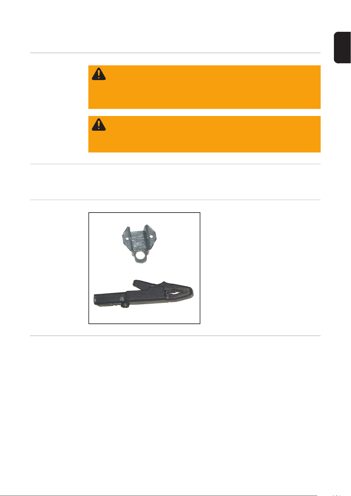
(1) Sensor-Halterung
(2) Klemme
Erforderliches
Werkzeug
(1)
(2)
- Schlitz-Schraubendreher
- Gabelschlüssel
Ohne Abbildung:
- diese Installationsanleitung
3
Page 4

Robotics Sensor umbauen
Sensor aus
Schweißhelm
ausbauen
Sensor auf Klemme montieren
2 Kunststoff-Schrauben und 2 Kunst-
1
stoff-Muttern mittels Schlitz-Schraubendreher und Gabelschlüssel
entfernen
Kunststoff-Schrauben und -Muttern
werden noch für weitere Arbeitsschritte
benötigt.
1
Sensor entnehmen
2
1
2
Klemme gemäß Abbildung in die Sen-
1
sor-Halterung einlegen
1
90°
1
Sensor gemäß Abbildung in die Sen-
2
sor-Halterung einsetzen
Sensor mit 2 Kunststoff-Schrauben
3
und 2 Kunststoff-Muttern fixieren
3
2
3
4
Page 5

General
Safety
General In order to visualise robot applications, the helmet sensor can be removed and attached
elsewhere, such as to the robot teach panel, using a clamp.
Scope of supply
WARNING! An electric shock can be fatal. Before opening the device
- Turn the mains switch to the "O" position
- Unplug the machine from the mains
- Put up an easy-to-understand warning sign to stop anybody inadvertently
switching it back on again
- Using a suitable measuring instrument, check to make sure that electrically
charged components (e.g. capacitors) have discharged
WARNING! Work that is carried out incorrectly can cause serious injury and damage. The following activities must only be carried out by trained and qualified personnel. Read the "Safety rules" chapter in the power source and system
components operating instructions.
(1) Sensor holder
(2) Clamp
EN
(2)
Tools required - Slotted screwdriver
- Flat spanner
(1)
Not illustrated:
- These Installation Instructions
5
Page 6
Relocating the robotics sensor
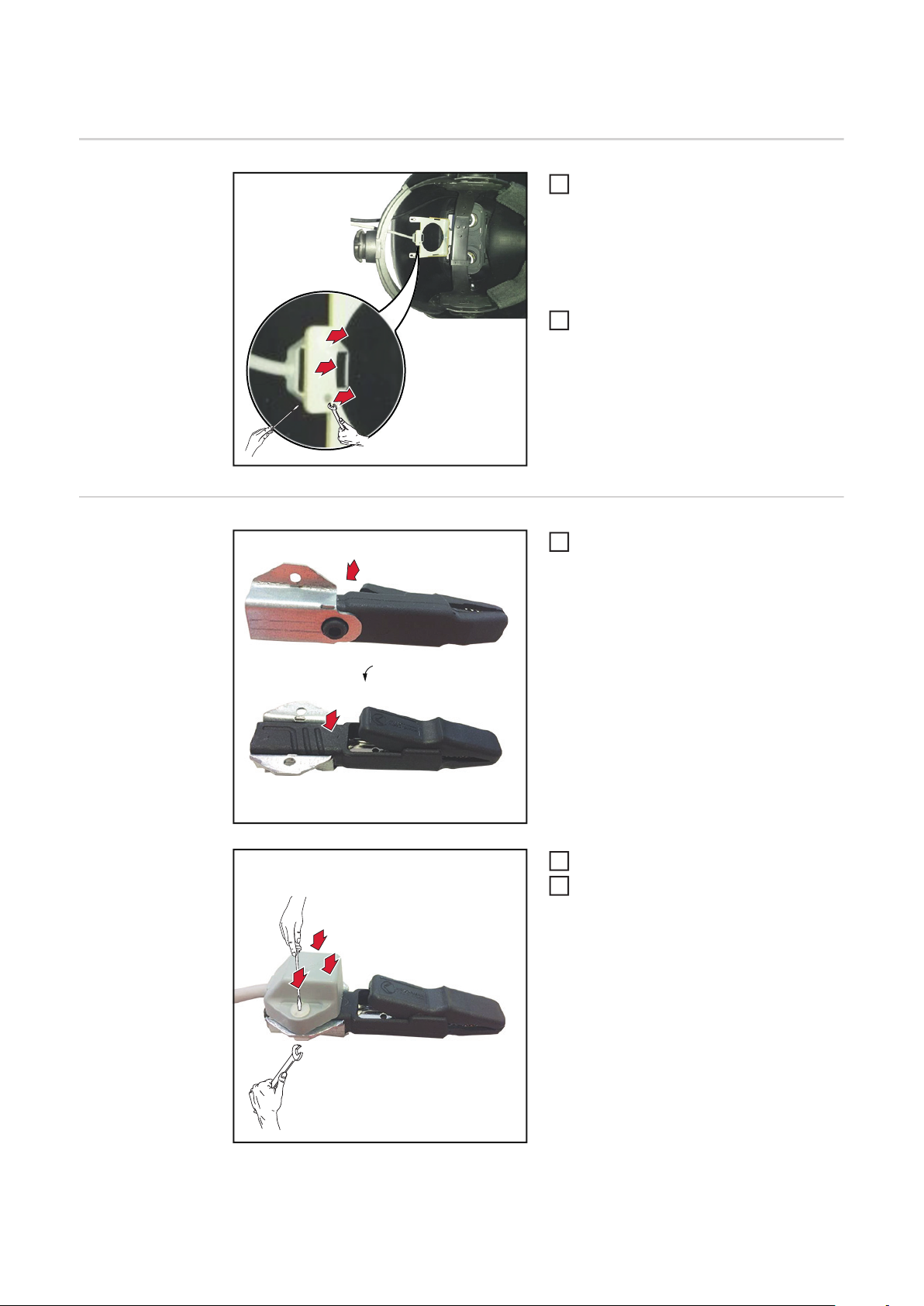
Removing the
sensor from the
welding helmet
Fitting the sensor
to the clamp
Remove the 2 plastic screws and 2 pla-
1
stic nuts using the slotted screwdriver
and the flat spanner
Retain the plastic screws and nuts for
later use.
Remove the sensor
1
2
1
2
Place clamp into the sensor holder as
1
shown
1
90°
1
Fit the sensor into the holder as shown
2
Fix sensor in place with 2 plastic
3
screws and 2 plastic nuts
3
2
3
6
Page 7

EN
7
Page 8

FRONIUS INTERNATIONAL GMBH
Froniusplatz 1, A-4600 Wels, Austria
Tel: +43 (0)7242 241-0, Fax: +43 (0)7242 241-3940
E-Mail: sales@fronius.com
www.fronius.com
www.fronius.com/addresses
Under http://www.fronius.com/addresses you will find all addresses
of our Sales & service partners and Locations
 Loading...