


Fronius prints on elemental chlorine free paper (ECF) sourced from certified sustainable forests (FSC).
/ Perfect Charging / Perfect Welding / Solar Energy
Virtual Welding 2.0
Operating Instructions
EN
Virtual welding system
[
42,0426,0089,EN 012-10072020

2

Contents
Safety rules ................................................................................................................................................ 7
Explanation of safety notices ................................................................................................................ 7
General ................................................................................................................................................. 7
Environmental conditions...................................................................................................................... 7
Obligations of the operator.................................................................................................................... 8
Obligations of personnel ....................................................................................................................... 8
Mains connection .................................................................................................................................. 8
Dangers from mains current ................................................................................................................. 8
EMC device classifications ................................................................................................................... 9
Specific hazards.................................................................................................................................... 10
Safety measures at the installation location and during transport ........................................................ 10
Safety measures in normal operation ................................................................................................... 11
Commissioning, maintenance and repair.............................................................................................. 11
Safety symbols...................................................................................................................................... 11
Data protection...................................................................................................................................... 11
Copyright............................................................................................................................................... 12
Disposal ................................................................................................................................................ 12
General information 13
General ...................................................................................................................................................... 15
Device concept ..................................................................................................................................... 15
Intended use ......................................................................................................................................... 15
Warning notices on the device.............................................................................................................. 16
Software and product updates.............................................................................................................. 17
Scope of delivery and optional function packages..................................................................................... 18
Scope of supply .................................................................................................................................... 18
Function packages................................................................................................................................ 19
EN
Controls, connections and mechanical components 21
Touchscreen and sensor ........................................................................................................................... 23
Touchscreen and sensor ...................................................................................................................... 23
Control elements and connections............................................................................................................. 24
Connection sockets on the StandUp Terminal...................................................................................... 24
Controls and connection sockets on the MobileCase........................................................................... 25
Location of the ventilation openings........................................................................................................... 27
Ventilation openings on the StandUp Terminal..................................................................................... 27
Ventilation openings on the MobileCase............................................................................................... 27
Installation 29
Before installation and commissioning....................................................................................................... 31
Safety.................................................................................................................................................... 31
Setup regulations .................................................................................................................................. 31
Installing the StandUp Terminal................................................................................................................. 33
Safety.................................................................................................................................................... 33
Screwing the mounting brackets to the StandUp Terminal................................................................... 33
Assembling the StandUp Terminal and tightening the screws.............................................................. 35
Waiting time until the power connection is established......................................................................... 38
Installing the MobileCase........................................................................................................................... 39
Safety.................................................................................................................................................... 39
Setting up the MobileCase, fitting the tool table.................................................................................... 39
Waiting time until the power connection is established......................................................................... 40
Fitting and connecting the system components......................................................................................... 41
Fitting and connecting the tool and other system components............................................................. 41
Switching on, getting started...................................................................................................................... 44
Connecting the mains cable and switching on the device .................................................................... 44
Getting started ...................................................................................................................................... 44
3

Start-up 45
Training concept and commissioning sequence ........................................................................................ 47
Training concept ................................................................................................................................... 47
Commissioning sequence..................................................................................................................... 47
First step of commissioning: creating a curriculum .................................................................................... 48
General ................................................................................................................................................. 48
Configuring a USB flash drive............................................................................................................... 48
Creating a knowledge check (test)........................................................................................................ 49
Saving content to the USB flash drive .................................................................................................. 50
Importing content .................................................................................................................................. 51
Merging content into a curriculum......................................................................................................... 55
Second step of commissioning: creating a course..................................................................................... 63
Uses of a course ................................................................................................................................... 63
Creating a course.................................................................................................................................. 63
Third step of commissioning: assigning courses ....................................................................................... 66
Assigning courses to the Virtual Welding system ................................................................................. 66
Assigning courses to multiple terminals................................................................................................ 67
Fourth step of commissioning: activating course mode, preparing the system for users .......................... 68
Activating course mode......................................................................................................................... 68
Preparing the system for users ............................................................................................................. 68
Ghost 69
Explanation and configuration options ....................................................................................................... 71
Explanation ........................................................................................................................................... 71
Creating a variable Ghost ..................................................................................................................... 71
Available modes on the Virtual Welding system 75
Course mode ............................................................................................................................................. 77
Explanation ........................................................................................................................................... 77
Activating course mode......................................................................................................................... 77
Profile.................................................................................................................................................... 78
Description of rankings lists, exporting course data.............................................................................. 80
Open mode ................................................................................................................................................ 82
Explanation ........................................................................................................................................... 82
Enabling open mode ............................................................................................................................. 82
Showroom mode........................................................................................................................................ 83
Explanation ........................................................................................................................................... 83
Enabling showroom mode .................................................................................................................... 83
Calibration 85
System calibration...................................................................................................................................... 87
Function ................................................................................................................................................ 87
Performing system calibration............................................................................................................... 87
Room calibration ........................................................................................................................................ 89
Function ................................................................................................................................................ 89
Performing room calibration.................................................................................................................. 89
Component calibration ............................................................................................................................... 91
Function ................................................................................................................................................ 91
Performing component calibration ........................................................................................................ 91
Changing the camera settings ................................................................................................................... 93
Function ................................................................................................................................................ 93
Changing the camera settings .............................................................................................................. 93
Additional settings 95
Licence management................................................................................................................................. 97
Function ................................................................................................................................................ 97
Opening licence management (Licensemanager) ................................................................................ 97
Installing a licence................................................................................................................................. 97
4

Changing the robot manufacturer .............................................................................................................. 98
Description ............................................................................................................................................ 98
Quiz............................................................................................................................................................ 99
Function ................................................................................................................................................ 99
Enabling/disabling or importing/exporting quizzes................................................................................ 99
Exporting a quiz .................................................................................................................................... 99
Creating a quiz...................................................................................................................................... 100
Importing a quiz .................................................................................................................................... 102
Setup menu 105
Permissions and opening the Setup menu ................................................................................................ 107
Different permissions ............................................................................................................................ 107
Access the Setup menu ........................................................................................................................ 107
Network menu item .................................................................................................................................... 108
Description ............................................................................................................................................ 108
Creating a cluster network .................................................................................................................... 108
Other settings menu item........................................................................................................................... 111
Viewing the licence list.......................................................................................................................... 111
Creating a backup (exporting data)....................................................................................................... 112
Management code ................................................................................................................................ 113
Language settings................................................................................................................................. 114
Importing data (only available to administrators) .................................................................................. 116
Viewing/changing country profiles (only available to administrators).................................................... 117
Restoring factory settings (only available to administrators)................................................................. 118
Performing sensor registration (only available to administrators) ......................................................... 119
Technical settings menu item .................................................................................................................... 122
Setting the time and date (only available to administrators) ................................................................. 122
Showing the NSB number..................................................................................................................... 122
Test screen (only available to administrators) ...................................................................................... 123
Setting the model .................................................................................................................................. 124
Enabling ScanDisk (only available to administrators) ........................................................................... 124
Performing touchscreen test (only available to administrators) ............................................................ 125
Adjusting the volume (only available to administrators)........................................................................ 126
EN
Troubleshooting, maintenance and disposal 129
Troubleshooting ......................................................................................................................................... 131
General ................................................................................................................................................. 131
Safety.................................................................................................................................................... 131
Troubleshooting .................................................................................................................................... 131
Maintenance and disposal ......................................................................................................................... 134
General ................................................................................................................................................. 134
Safety.................................................................................................................................................... 134
Maintenance at every start-up .............................................................................................................. 134
Disposal ................................................................................................................................................ 134
Update 135
Updating the software ................................................................................................................................ 137
Preparing for the update ....................................................................................................................... 137
Updating the software ........................................................................................................................... 146
Technical data 149
Technical data............................................................................................................................................ 151
Special voltages.................................................................................................................................... 151
StandUp Terminal, MobileCase ............................................................................................................ 151
Standards.............................................................................................................................................. 151
5

6

Safety rules
EN
Explanation of
safety notices
DANGER!
Indicates immediate danger.
► If not avoided, death or serious injury will result.
WARNING!
Indicates a potentially hazardous situation.
► If not avoided, death or serious injury may result.
CAUTION!
Indicates a situation where damage or injury could occur.
► If not avoided, minor injury and/or damage to property may result.
NOTE!
Indicates a risk of flawed results and possible damage to the equipment.
General The device has been manufactured in line with the state of the art and according to recog-
nised safety standards. If used incorrectly or misused, however, it can cause:
- Serious or fatal injury to the operator or third parties
- Damage to the device and other material assets belonging to the operating company
- Inefficient operation of the device
All persons involved in commissioning, operating, maintaining and servicing the device
must:
- Be suitably qualified
- Have fully read, understood and precisely followed these Operating Instructions
The Operating Instructions must always be at hand wherever the device is being used. In
addition to the Operating Instructions, all applicable local rules and regulations regarding
accident prevention and environmental protection must also be followed.
All safety and danger notices on the device:
- Must be kept in a legible state
- Must not be damaged/marked
- Must not be removed
- Must not be covered, pasted, or painted over
For the location of the safety and danger notices on the device, refer to the "General" chapter of the device Operating Instructions.
Before switching on the device, rectify any faults that could compromise safety.
This is for your personal safety!
Environmental
conditions
Operation or storage of the device outside the stipulated area will be deemed as not in accordance with the intended purpose. The manufacturer shall not be held liable for any damage arising from such usage.
7

The device must only be installed and operated inside dry and enclosed premises.
Ambient temperature range:
- during operation: - 10 °C to + 35 °C (14 °F to 95 °F)
- during transport and storage: - 25 °C to + 55 °C (-13 °F to 131 °F)
Relative humidity:
- up to 50 % at 35 °C (95 °F)
- up to 90 % at 20 °C (68 °F)
The surrounding air must be free from dust, acids, corrosive gases or substances, etc.
Can be used at altitudes of up to 2000 m (6500 ft)
Obligations of the
operator
Obligations of
personnel
The operator undertakes:
- To read and understand these Operating Instructions.
- To hand the key of the device only to persons who are familiar with the product
The operator must only allow persons to work with the device who:
- Are familiar with the fundamental instructions regarding safety at work and accident
prevention and have been instructed in how to use the device
- Have read and understood these Operating Instructions and have confirmed as much
with their signatures
- Are trained to produce the required results (live work or training)
Checks must be carried out at regular intervals to ensure that personnel are working in a
safety-conscious manner.
Before using the device, all persons instructed to do so undertake:
- To observe the basic instructions regarding safety at work and accident prevention
- To have read and understood these Operating Instructions
Before leaving the workplace, ensure that people or property cannot come to any harm in
your absence.
Mains connection The mains voltage and frequency must conform to the data on the rating plate.
The Virtual Welding system must be connected to a properly installed, fused and earthed
mains socket.
If the device is shipped without a standard domestic cable, fit and use a mains plug and
cable in accordance with local standards.
An electric shock is potentially life threatening and can be fatal. The mains plug must be
fitted and connected by trained personnel only.
Route the mains cable so as to avoid any risk of injury to persons (e.g. tripping) or damage
to the mains cable.
Dangers from
mains current
8
An electric shock is potentially life threatening and can be fatal.
Do not touch live parts either inside or outside the device.

All cables and leads must be secured, undamaged, insulated and adequately dimensioned. Loose connectors, scorched, damaged or inadequately dimensioned cables and
leads must be replaced immediately.
Do not wrap cables or leads around the body or parts of the body.
Arrange for the mains cable to be checked regularly by a qualified electrician to ensure the
ground conductor is functioning properly.
The device must only be operated on a mains supply with a ground conductor and a socket
with a ground conductor contact.
If the device is operated on a grid without a ground conductor and in a socket without a
ground conductor contact, this will be deemed gross negligence. The manufacturer shall
not be held liable for any damage arising from such usage.
Switch off unused devices.
Wear a safety harness if working at height.
Before working on the device, switch it off and pull out the mains plug.
EN
EMC device classifications
Attach a clearly legible and easy-to-understand warning sign to the device to prevent anyone from plugging the mains plug back in and switching it on again.
After opening the device:
- Discharge all components that store an electrical charge
- Ensure that all components in the device are de-energised.
If work on live parts is required, appoint a second person to switch off the main switch at
the right moment.
Repairs (e.g. opening of the device) must only be carried out by suitably trained and qualified personnel. In the event of a fault, disconnect the mains plug immediately and have
repairs carried out by trained and qualified personnel.
- The device must be disconnected from the power supply before carrying out repairs
- Use only original spare parts
- Switch off before removing the mains plug
Virtual Welding is an emission class A device.
Devices with emission class A
- Are only designed for use in an industrial setting
- Can cause conducted and emitted interference in other areas.
In certain cases, even though a device complies with the standard limit values for emissions, it may affect the application area for which it was designed (e.g. when there is sensitive equipment at the same location, or if the site where the device is installed is close to
either radio or television receivers).
If this is the case, then the operator is obliged to take appropriate action to rectify the situation.
9

Check for possible problems, and check and evaluate neighbouring devices' resistance to
interference according to national and international requirements. For example:
- Safety devices
- Network, signal and data transfer lines
- IT and telecommunications devices
- Measuring and calibrating devices
Supporting measures for avoidance of EMC problems:
a) Mains supply
- Use only with the power cable supplied
- If electromagnetic interference arises despite the correct mains connection, addi-
tional measures are necessary (e.g. use of a suitable line filter)
b) No changes to the device
- Changes made to the device without prior consent from the manufacturer may re-
sult in loss of type approval
c) If the device appears to be interfering with the reception of radio or TV signals or the
operation of other equipment:
- Turn the device on and off to confirm that it is a source of interference
- If this identifies the device as a source of interference, remedy the fault by the in-
terference suppression measures listed below
d) Interference suppression measures
- Shield other devices nearby
- Set up the device well away from the affected receiver
- Turn the device away from the affected receiver
- Turn the antenna of the affected receiver in a different direction
- Connect the device to a different AC socket so that the device and the affected
receiver use different circuits.
- Only connect the device to a socket that is earthed. Removing the earth can am-
plify high-frequency emissions and cause an electric shock with fatal consequences. Do not use an AC adapter or extension cable
- If the measures described above do not resolve the problem, contact the manu-
facturer or a qualified radio and TV technician
Specific hazards Special provisions apply in areas at risk of fire or explosion
- observe relevant national and international regulations.
Always keep ventilation openings clear. For more details on the position of the ventilation
openings, see section Location of the ventilation openings from page 27.
The ambient temperature must not exceed 35 °C (95 °F).
The device must not be moved using a crane.
If the StandUp Terminal is set up incorrectly it could topple over, leading to injury and material damage. The StandUp Terminal must only be set up by trained personnel on a firm,
horizontal surface and secured to the wall and the floor using the brackets provided.
For more details on installing the StandUp Terminal, see section Installing the StandUp
Terminal from page 33.
Safety measures
at the installation
location and during transport
When transporting the device, ensure that the relevant national and local guidelines and
accident prevention regulations are observed. This applies especially to guidelines regarding the risks arising during transport.
Transport the device only in the original packaging. The original packaging is available
from the manufacturer.
10

Do not lift or transport operational devices. Switch off devices before transport or lifting.
Safety measures
in normal operation
Use internal directives and checks to ensure that the workplace environment is always
clean, organised and tidy.
After transport, before installation and commissioning, it is essential to visually inspect the
device for damage. Have a trained service technician repair any damage before installation
and commissioning.
Only operate the device when all safety devices are fully functional. If the safety devices
are not fully functional, there is a risk of:
- Serious or fatal injury to the operator or third parties
- Damage to the device and other material assets belonging to the operating company
- Inefficient operation of the device
Any safety devices that are not functioning properly must be repaired before switching on
the device.
Never bypass or disable safety devices.
Before switching on the device, ensure that no one is likely to be endangered.
Check the device at least once a week for obvious damage and proper functioning of safety
devices.
EN
Commissioning,
maintenance and
repair
Safety symbols Devices with the CE mark satisfy the essential requirements of the low-voltage and elec-
It is impossible to guarantee that bought-in parts are designed and manufactured to meet
the demands made of them, or that they satisfy safety requirements.
- Use only original spare and wearing parts (also applies to standard parts).
- Do not carry out any modifications, alterations, etc. to the device without the manufacturer's consent.
- Components that are not in perfect condition must be replaced immediately.
- When ordering, please give the exact designation and part number as shown in the
spare parts list, as well as the serial number of your device.
The housing screws provide the ground conductor connection for earthing the housing
parts.
Only use original housing screws in the correct number and tightened to the specified
torque.
tromagnetic compatibility directives (e.g. relevant product standards of the EN 60 974 series).
Fronius International GmbH hereby declares that the device is compliant with Directive
2014/53/EU. The full text on the EU Declaration of Conformity can be found at the following
address: http://www.fronius.com
Devices marked with the CSA test mark satisfy the requirements of the relevant standards
for Canada and the USA.
Data protection The user is responsible for the safekeeping of any changes made to the factory settings.
The manufacturer accepts no liability for any deleted personal settings.
11

Copyright Copyright of these operating instructions remains with the manufacturer.
The text and illustrations are all technically correct at the time of printing. We reserve the
right to make changes. The contents of the operating instructions shall not provide the basis for any claims whatsoever on the part of the purchaser. If you have any suggestions for
improvement, or can point out any mistakes that you have found in the instructions, we will
be most grateful for your comments.
Disposal Do not dispose of this device with normal domestic waste! To comply with the European
Directive on Waste Electrical and Electronic Equipment and its implementation as national
law, electrical equipment that has reached the end of its life must be collected separately
and returned to an approved recycling facility. Any device that you no longer require must
either be returned to your dealer or given to one of the approved collection and recycling
facilities in your area. Ignoring this European Directive may have potentially adverse affects on the environment and your health!
12

General information


General
EN
Device concept
Virtual Welding is used to teach welding in
a realistic environment. The following benefits are provided by Virtual Welding:
- Very low cost of training No consumables are required (wire electrodes, welding gas, etc.)
- The trainees are not exposed to the
hazards of welding (heat, welding fumes, welding spatter, noise, etc.)
- The learning progress of the trainees is
documented and can be compared
with each other
- The learning content can be adapted to
suit your needs
- Many different tasks can be simulated
with the help of the different welding
torches and workpieces
- etc.
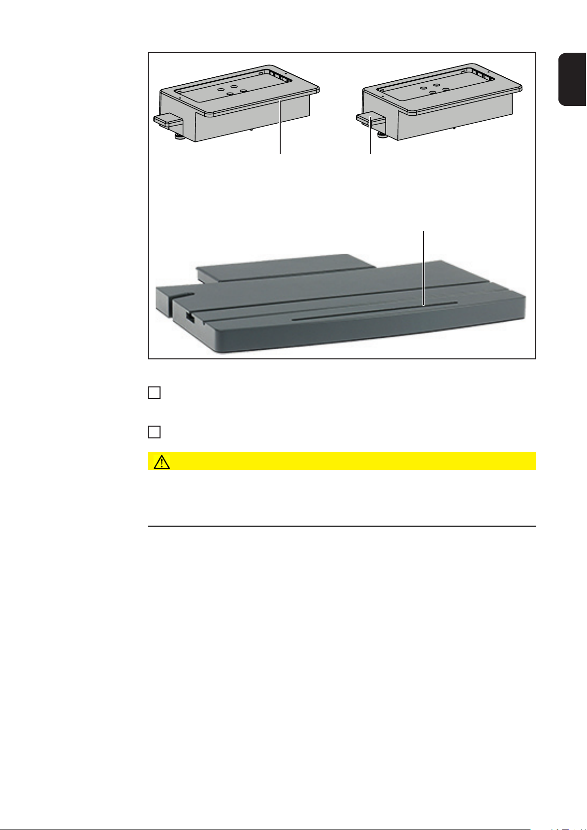
Virtual Welding is available as a StandUp
Terminal for stationary applications and as
a MobileCase for portable use.
StandUp Terminal
MobileCase
Intended use The device is to be used exclusively for its intended purpose.
15

The device is intended for welding simulation only with the software and hardware supplied
by the manufacturer.
Any use above and beyond this purpose is deemed improper.
The manufacturer shall not be held liable for any damage arising from such usage.
Intended use also means:
- Fully reading and understanding all the instructions given in the Operating Instructions
- Fully reading and understanding all warning notices on the device
- Performing all stipulated inspection and servicing work
- Establishing the mains connection according to the specifications on the rating plate
- Setting up in a dry and enclosed environment
The device must never be:
- Modified without authorisation
- Handled improperly
- Operated with software other than that supplied by the manufacturer
- Operated, maintained or repaired without observing the Operating Instructions
The device is designed for use in a dry and enclosed environment. The manufacturer is not
liable for any damage caused by use in a different environment.
The manufacturer accepts no liability for inadequate or incorrect training results.
Warning notices
on the device
Warning notices and safety symbols are affixed to the StandUp Terminal and MobileCase.
These warning notices and safety symbols must not be removed or painted over. They
warn against incorrect operation, as this may result in serious injury and damage.
16

Incorrect operation or poorly executed work can cause serious injury or damage. The device may only be installed, repaired and maintained by trained and qualified personnel. The
following documents must be completely read and understood:
- These Operating Instructions
- All the Operating Instructions for the system components, especially the safety rules
Do not dispose of used devices with domestic waste. Dispose of them according to the safety rules.
EN
Software and
product updates
Due to software updates, you may find that your device has certain functions that are not
described in these Operating Instructions or vice versa. Certain illustrations may also differ
slightly from the actual controls on your device, but these controls function in exactly the
same way.
17

Scope of delivery and optional function packages
Scope of supply In addition to the StandUp Terminal or MobileCase, the following system components are
supplied:
Work table
Workpiece holder Single-V butt weld layer 1 (square butt weld) workpie-
ce
Fillet weld workpiece
18
Single-V butt weld layer 2 and 3 (square butt weld)
workpiece

EN
Function packages
Pipe workpiece
2 NFC keys
Supplied with the StandUp Terminal, but not shown:
- 3D glasses
- 4 keys
- 4 screws M8x80 mm with washers, for screwing together the upper and lower parts
- Mounting bracket including 4 screws M8x16 mm and washers
- This document
- Mains cable (for connecting to a power socket)
- Cable for 3D glasses
- Network cable
Supplied with the MobileCase, but not shown:
- 3D glasses
- 2 keys
- This document
- Mains cable (for connecting to a power socket)
- Cable for 3D glasses
- Network cable
The function packages are not included with the Virtual Welding system. At least one of the
following function packages must be ordered with the Virtual Welding system.
MIG/MAG function package TIG function package
Robotics function package
19

Rod electrode function package
20

Controls, connections and mechani-
cal components


Touchscreen and sensor
(2)
(1)
(2)
Touchscreen and
sensor
EN
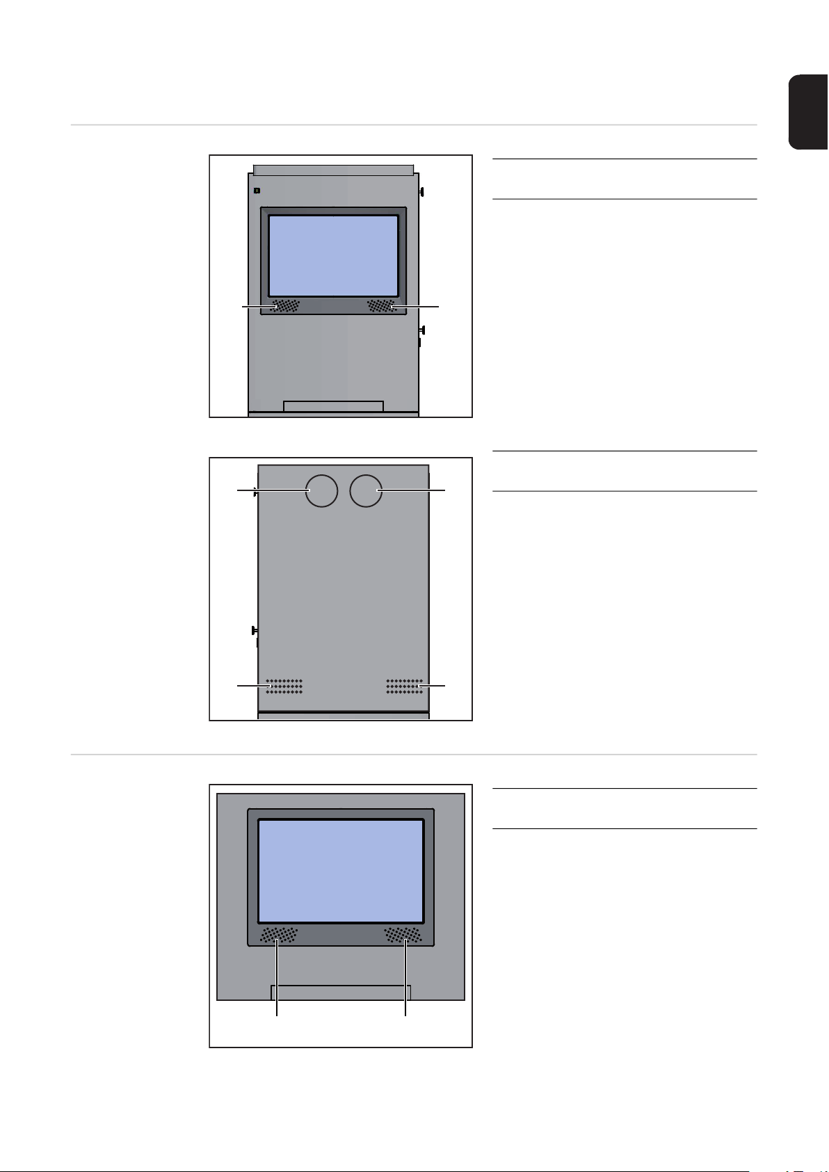
Touchscreen and sensor on the StandUp Terminal
The touchscreen (1) allows intuitive operation by means of virtual buttons.
The sensor (2), in conjunction with the supplied NFC keys, performs the following functions:
- Touch sensor with the NFC key once =
Open terminal management in order to create curricula, for example - see section
First step of commissioning: creating a curriculum from page 48
- Touch the sensor with the NFC key twice =
Open the Setup menu - for more details, see section Permissions and opening the
Setup menu from page 107
Sensor on MobileCase
23

Control elements and connections
(1) (2) (3) (4)
Connection sockets on the StandUp Terminal
(1) Connection for the workpiece
(2) Connection for robotics clip or
(3) Connection 1 for welding torch
(4) Connection 2 for welding torch
holder
for connecting the sensor cable of
the workpiece holder
filler material
for connecting the sensor cable of
the robotics clip;
for connecting the sensor cable of
the filler material (TIG)
for connecting the sensor cable of
the welding torch;
for connecting the sensor cable of
the electrode holder
for connecting the control cable of
the welding torch;
for connecting the control cable of
the electrode holder
Front of the StandUp Terminal
24

(5) LAN connection socket
(5) (6) (7) (8)
(9)
(10)
(11)
(4) (5)(3)(2)(1)
(7) (6)(8)(9)
for connecting a LAN network cable
(6) 3D glasses connection socket
for connecting the data cable of the
3D glasses
(7) USB port
for connecting the power cable of
the 3D glasses
(8) Connection for external display
provided
for connecting an external monitor
or projector
(After connecting the monitor/projector, restart the Virtual Welding
system)
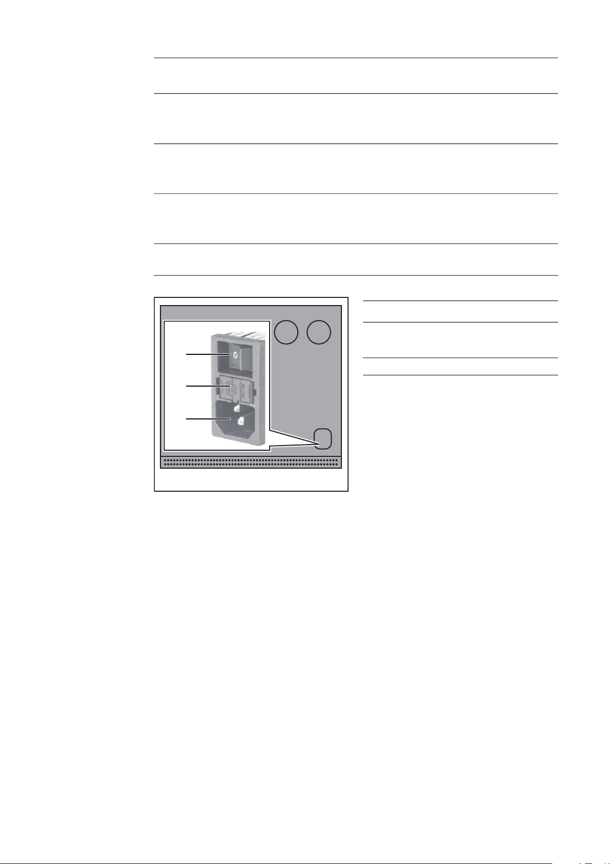
(9) Mains switch
(10) Fuse
2 x 3.15 A slow-blow
(11) Mains connection
EN
Controls and connection sockets
on the MobileCase
Rear of StandUp Terminal
The controls and connection sockets illustrated below are located on the right side panel
of the MobileCase.
(1) Connection for external display
provided
for connecting an external monitor
or projector
(After connecting the monitor/projector, restart the Virtual Welding
system)
(2) Sensor
See section Touchscreen and
sensor on page 23
(3) 3D glasses connection socket
for connecting the data cable of the
3D glasses
(4) USB port
for connecting the power cable of
the 3D glasses
25
(5) LAN connection socket
(9)
(10)
(11)
for connecting a LAN network cable
(6) Connection 1 for welding torch
for connecting the control cable of the welding torch;
for connecting the control cable of the electrode holder
(7) Connection 2 for welding torch
for connecting the sensor cable of the welding torch;
for connecting the sensor cable of the electrode holder
(8) Connection for robotics clip or filler material
for connecting the sensor cable of the robotics clip;
for connecting the sensor cable of the filler material (TIG)
(9) Connection for the workpiece holder
for connecting the sensor cable of the workpiece holder
(10) Mains switch
(11) Fuse
2 x 3.15 A slow-blow
Rear of MobileCase
(12) Mains connection
26
Location of the ventilation openings
(1)
(1)
(1)
(1)
(1)
(1)
(1)(1)
Ventilation openings on the StandUp Terminal
(1) Ventilation openings at the front
(2) Ventilation openings at the rear
EN
of the device
of the device
Ventilation openings on the MobileCase
(1) Ventilation openings at the front
of the device
27

(2) Ventilation openings at the rear
(2)
(2)
(2)
of the device
28

Installation

Before installation and commissioning
EN
Safety
Setup regulations
WARNING!
Danger due to incorrect operation and incorrectly performed work.
This can result in serious injury and damage to property.
► All the work and functions described in this document must only be carried out by
trained and qualified personnel in accordance with the applicable national and international standards.
► Read and understand this document.
► Read and understand all the Operating Instructions for the system components, espe-
cially the safety rules.
WARNING!
Danger from StandUp Terminal falling or toppling over.
This can result in serious injury and damage to property.
► Bolt StandUp Terminal securely to the ground and to a wall.
► The screws for fastening to the ground/wall are not included in the scope of supply of
the device. The installer is responsible for selecting the right type of screws or bolts.
► For more details on installing the StandUp Terminal, see section Installing the Stan-
dUp Terminal from page 33.
WARNING!
Danger due to unacceptable environmental conditions.
This can result in serious injury and damage to property.
► Observe the following requirements for all Virtual Welding systems.
Before installation, ensure that the following conditions are met:
- Dry and enclosed location
- Firm, level and supportive surface
- Unobstructed access to the device
- Device has no transport damage and is in fault-free condition
Do not set up the device close to life-saving facilities, such as:
- Emergency exits
- Fire extinguishers
- First-aid cabinets
Do not place the device near heat sources, such as:
- Radiators
- Air-conditioning units
- Sun terraces
- Strong sunlight
Protect the device from severe environmental impact, such as:
- Smoke and dirt
- Rain and moisture
- Strong magnetism or radio waves
- Cold
31

Ensure that the permissible environmental conditions are maintained at all times. For more
details on environmental conditions, see section Environmental conditions on page 7.
Special provisions apply in areas at risk of fire or explosion - observe relevant national and
international regulations.
NOTE!
Risk of frequency interference.
This can lead to malfunctions.
► Keep metallic objects away from the device.
► Ensure a minimum distance of 4 m (157.48 inches) between multiple Virtual Welding
devices.
32

Installing the StandUp Terminal
1
EN
Safety
Screwing the
mounting brackets to the StandUp Terminal
WARNING!
Danger from electric current.
This can result in serious injury or death.
► Before beginning work, switch off the device and disconnect from the mains supply.
► Secure the device against it being switched back on again.
WARNING!
Danger due to improper installation.
This can result in serious injury and damage to property.
► Observe the instructions in the section Setup regulations from page 31.
(1)(1)(1) (1)
Top of StandUp Terminal
Screw the supplied mounting brackets to the top of the StandUp Terminal (1) as
shown below, but do not yet tighten the screws
- Use four M8x16 mm screws and washers
- Do not tighten the four screws until the StandUp Terminal is in its final installation
position and the mounting brackets have been pushed against the wall
33

Top of StandUp Terminal, side view
(2)(3)(3)(3) (3) (2)
(2) = Mounting bracket
(3) = Screws with washers
34

Assembling the
(2)
(1)
(4)
(2)
(3) (3)(3) (3)
(4)
1
2
3
4
5
6
(5)(6) (6)(5)
(5)
(6)
(7)
(6)
(7)
(5)
9
StandUp Terminal
and tightening
the screws
Place the bottom part in its final installation position
- Make sure that the mounting bra-
ckets (2) extend to the wall
Place the upper part on the lower part
Screw the two parts together using the
four socket screws (1) M8x80 mm supplied
Screw the StandUp Terminal to the
wall at the mounting brackets (2)
- Fixings for securing the terminal to
the wall are not included in the
scope of supply. The installer is
responsible for selecting the right
fixings.
Tighten the four screws M8x16 mm (3)
of the mounting brackets
Screw the StandUp Terminal to the
ground through the holes (4)
- Fixings for securing the terminal to
the ground are not included in the
scope of supply. The installer is
responsible for selecting the right
fixings.
EN
Loosen the screws (5) while holding one of the brackets (6)
7
Guide the brackets (6) down until the screws (5) can be screwed through the holes (7)
8
Tighten the screws (5)
35

Tool table, standard mounting:
(9)
(8)
10
Slide the tool table (8) fully into the
opening (9)
Tool table, overhead mounting:
NOTE!
To aid clarity, the mounting brackets for wall mounting have been removed in the
following images. However, the StandUp Terminal must always be screwed to the
wall with the mounting brackets.
► For more details on the mounting brackets, see section Screwing the mounting brac-
kets to the StandUp Terminal from page 33.
36

(10)(11)
Top of StandUp Terminal
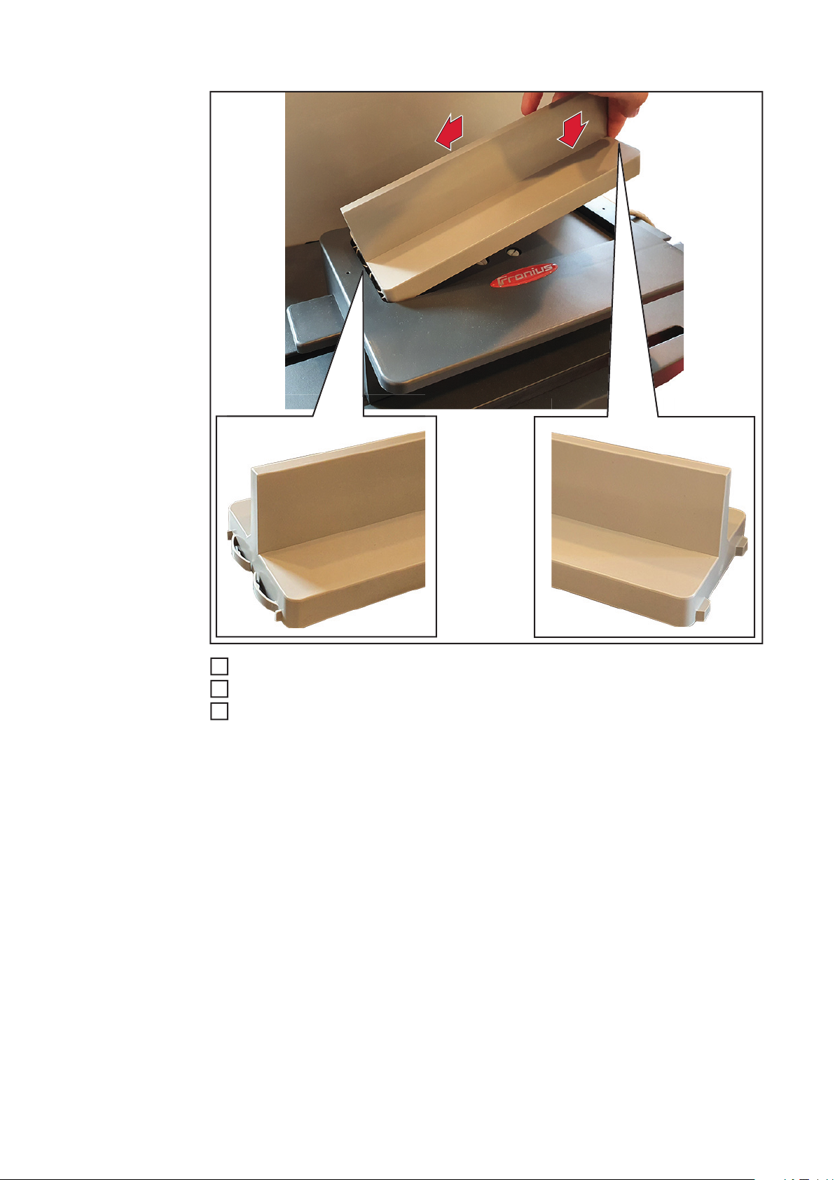
Lock the tool table in the holders (10) and (11) as shown below
5
EN
(11)
Top of StandUp Terminal with tool table fitted
(10) = Holder
(11) = Holder
(12) = Tool table
(12) (10)
CAUTION!
Danger from falling tool table.
This can result in injury and damage to property.
► Always make sure the tool table is locked in the holders (10) and (11) as shown above.
37

Waiting time until
the power connection is established
CAUTION!
Risk of poor acclimatisation of components by connecting the device to the mains
too early.
This can result in damage to the device
► Do not connect the device to the mains and switch it on until at least four hours after
the installation has been completed.
38

Installing the MobileCase
1
2
EN
Safety
Setting up the
MobileCase, fitting the tool table
WARNING!
Danger from electric current.
This can result in serious injury or death.
► Before beginning work, switch off the device and disconnect from the mains supply.
► Secure the device against it being switched back on again.
WARNING!
Danger due to improper installation.
This can result in serious injury and damage to property.
► Observe the instructions in the section Setup regulations from page 31.
Take the MobileCase and the tool table
out of the transport case
Place the MobileCase in the desired
position
39

(2)(1)
3
Slide the tool table (2) fully into the opening (1)
Refer to the Installation Instructions of the relevant installation kit for the overhead
4
mounting of the tool table
CAUTION!
Risk of poor acclimatisation of components by connecting the device to the mains
too early.
This can result in damage to the device
► Do not connect the device to the mains and switch it on until at least four hours after
the installation has been completed.
Waiting time until
the power connection is established
CAUTION!
Risk of poor acclimatisation of components by connecting the device to the mains
too early.
This can result in damage to the device
► Do not connect the device to the mains and switch it on until at least four hours after
the installation has been completed.
40

Fitting and connecting the system components
1
Fitting and connecting the tool
and other system
components
(2) (2)
(1)
EN
(2)
(2)
NOTE!
The workpiece holder (1) is shown in the standard mounting position. The workpiece holder (1) can be fitted in other positions on the tool table. These are displayed
at the end of this section.
Place the workpiece holder (1) on the tool table
- Make sure that the workpiece holder is locked in the guides (2)
Connect the workpiece holder sensor cable to the Virtual Welding system
2
(2) (2)
41
1
5
2
Insert the desired workpiece into the workpiece holder as shown above
3
Connect the 3D glasses to the Virtual Welding system
4
Connect the welding torch/electrode holder to the Virtual Welding system
For more information on the connection sockets
- on the StandUp Terminal, see section Connection sockets on the StandUp Termi-
nal from page 24
- on the MobileCase, see section Controls and connection sockets on the Mobi-
leCase from page 25
Alternative mounting positions of the workpiece holder:
42
EN
1
(3)
Alternative mounting positions of workpiece holder 1:
Insert the overhang (3) into the slot (4) on the tool table
Alternative mounting positions of workpiece holder 2:
Insert the overhang (5) into the slot (4) on the tool table
1
(5)
(4)
CAUTION!
Danger from falling workpiece holder.
This can result in injury and damage to property.
► The two alternative mounting positions must not be used for overhead exercises.
► For overhead exercises, only use the standard mounting position.
43

Switching on, getting started
(1)
(2)
1
2
3
2
5
Connecting the
mains cable and
switching on the
device
WARNING!
Danger from electric current.
This can result in serious injury or death.
► Use only the supplied mains cable to connect to the mains.
► Only plug the mains cable into a correctly earthed socket.
CAUTION!
Risk of poor acclimatisation of components by connecting the device to the mains
too early.
This can result in damage to the device
► Do not connect the device to the mains and switch it on until at least four hours after
the installation has been completed.
Plug the mains cable into the connection socket (1)
Plug the mains cable into a power socket
Set the mains switch (2) to the "I" position
Getting started Confirm the displayed licence agreement
44
1
Set time and date
- Follow the instructions on the touchscreen
Perform sensor registration
3
- Follow the instructions on the touchscreen
- Create at least one NFC key for administrators
Choose model/camera position:
4
- Follow the instructions on the touchscreen
Perform room calibration:
- See section Room calibration from page 89
Performing system calibration:
6
- See section Performing system calibration from page 87
The Virtual Welding system is now fully functional.

Start-up


Training concept and commissioning sequence
Training concept - The curriculum is used as the basis for all Virtual Welding learning content
- A curriculum is divided into individual chapters
- The chapters contain all relevant content for the trainees. This content includes:
- Theory: Explanation of welding processes, introductions, etc.
- Knowledge check: Tests to verify the knowledge acquired, etc.
- Training: Practical welding tasks, etc.
- WPS (Welding Procedure Specification): welding procedure specification
- Individual courses can be compiled for the desired group of trainees from the curricu-
lum
- If there are multiple Virtual Welding systems in a network, the courses can be as-
signed to different Virtual Welding systems, such as:
- Course A is assigned to the systems used for basic training
- Course B is assigned to the systems used for advanced training
EN
Commissioning
sequence
1. Create a curriculum and chapters
– This step is only necessary if no Fronius licences have been purchased with the
Virtual Welding system
– If Fronius licences have been purchased with the system, several curricula are
pre-installed on the system
2. Create individual courses from the curriculum
3. Assign the courses to the desired Virtual Welding systems (only necessary if multiple
Virtual Welding systems are in use)
4. Enable course mode (must be performed separately on each Virtual Welding system)
and prepare Virtual Welding systems for users
The above steps are described in detail in the following sections.
The following sections describe the MIG/MAG welding process. The procedure is the same
for the all other welding processes.
47

First step of commissioning: creating a curriculum
2
3
General - A curriculum needs to be created only if no Fronius licences have been purchased with
the Virtual Welding system.
- If you purchased Fronius licences with the system, this section can be skipped and
you can start with creating courses. For details, see section Creating a course from
page 63
- Even if you purchased Fronius licences with the system, you may still create your
own curricula. However, this is not necessary.
Configuring a
USB flash drive
Connect a USB flash drive to the USB port of the Virtual Welding system
1
Touch the NFC key on the Virtual Welding system sensor to open terminal management
- For the sensor location, see section Touchscreen and sensor on page 23
(2)
(1)
Select button (1)
Select tab (2)
4
(3)
48

Select button (3) to configure the USB flash drive
2
(1)
(2)
(1)
(3)
(4)
(5)
(6)
(7)
4
5
EN
Creating a knowledge check (test)
- The knowledge check is part of the course mode and is used to check whether the
learned theory content has been understood.
- It is recommended to include in the knowledge check only questions that can be answered through the theoretical content provided.
Disconnect the USB flash drive from the Virtual Welding system and plug it into a PC
1
Open the USB flash drive on the PC
Open "QuizEditor.exe"
3
Select button (1)
Fill in text boxes (2) - (6) for the first question of the knowledge check
5
Select button (7) to add another question
6
- Repeat these steps as many times as you like
NOTE!
It is recommended that the knowledge check be given a practical and unique file
name when saving, since this file name can be transferred to the Virtual Welding
system when later imported (this means that you do not have to re-enter the name
of the knowledge check on the Virtual Welding system).
49

(8)
Saving content to
the USB flash
drive
Select button (8) and save the knowledge check in the "knowledgecheck" folder on the
7
USB flash drive
- Saving is only possible once all the fields in theQuizEditor have been completed
If desired, a quiz can also be created. For details, see section Quiz from page 99.
NOTE!
It is recommended that the learning content and the WPS be given a practical and
unique file name when saving, since this file name can be transferred to the Virtual
Welding system when later imported (this means that you do not have to re-enter the
name of the learning content and the WPS on the Virtual Welding system).
50
Copy all desired learning content to the "theory" folder
1
(1)
(2)
(3)
3
1
- Use PDF only
Copy customer-specific WPS to the "wps" folder
2
- WPS from Fronius are already installed on the system
- The knowledge check created in the previous step is already in the "knowledgecheck"
folder
- the "quiz" folder already contains a Quiz, if this has been created
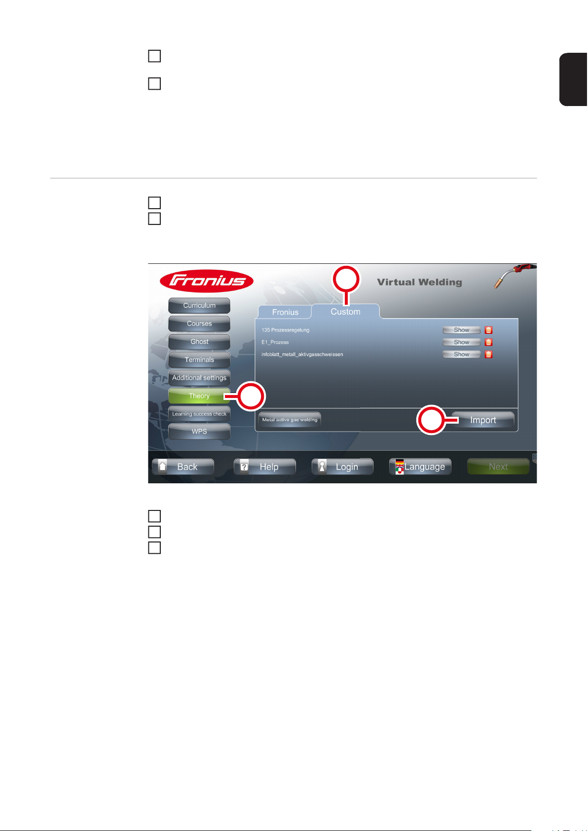
Importing content Connect the USB flash drive to the USB port of the Virtual Welding system
Touch the NFC key on the Virtual Welding system sensor to open terminal manage-
2
ment
- For the sensor location, see section Touchscreen and sensor on page 23
EN
Import theory content:
Select button (1)
Select tab (2)
4
Select button (3)
5
51

(4)
6
(6)
(7)
(8)
10
Import theory content:
Select the desired file, for example (4)
Select button (5)
7
(5)
52
Import theory content:
Make sure the correct welding process is selected (6)
8
Select checkbox (7) to use the original file name
9
Select button (8) to import the file

(10)
13
14
EN
(9)
Import a knowledge check:
Select button (9)
11
Select tab (10)
12
Select button (11)
(12)
(11)
(13)
Import a knowledge check:
Select the desired file, for example (12)
Select button (13)
15
53

(15)
17
(17)
(18)
(19)
21
(16)
Import a knowledge check:
Make sure that the correct welding process is selected (14)
16
Select checkbox (15) to use the original file name
Select button (16) to import the file
18
(14)
54
Import a WPS:
Select button (17)
19
Select tab (18)
20
Select button (19)

(20)
23
25
Import a WPS:
Select the desired file, for example (20)
22
Select button (21)
EN
(21)
(23)
(22)
(24)
Import a WPS:
Make sure that the correct welding process is selected (22)
24
Select checkbox (23) to use the original file name
Select button (24) to import the file
26
Plug the USB flash drive into the system
27
- The USB flash drive can be used to store curricula (backup copy), for example
Merging content
into a curriculum
- In the following section, the previously imported content is merged to form a curriculum.
55

- The curriculum can be divided into individual chapters as desired
(3)
- It is recommended that each chapter builds on previously learned knowledge. For
example, a chapter with easy welding tasks and related content, a chapter with
medium welding tasks and related contents, and so forth.
- Individual courses for users can be created from the curriculum. For details, see section Creating a course from page 63.
(1)
(2)
Select button (1)
1
Select button (2)
2
Create the first chapter for the new curriculum:
56
Select button (3)
3

(4)
(11)
7
(5)
Select which content types are to be inserted into the chapter (4)
4
- Depending on your needs, you can select individual content types or all content
types
Select button (5)
5
- In the next steps, the individual contents are inserted into the chapter
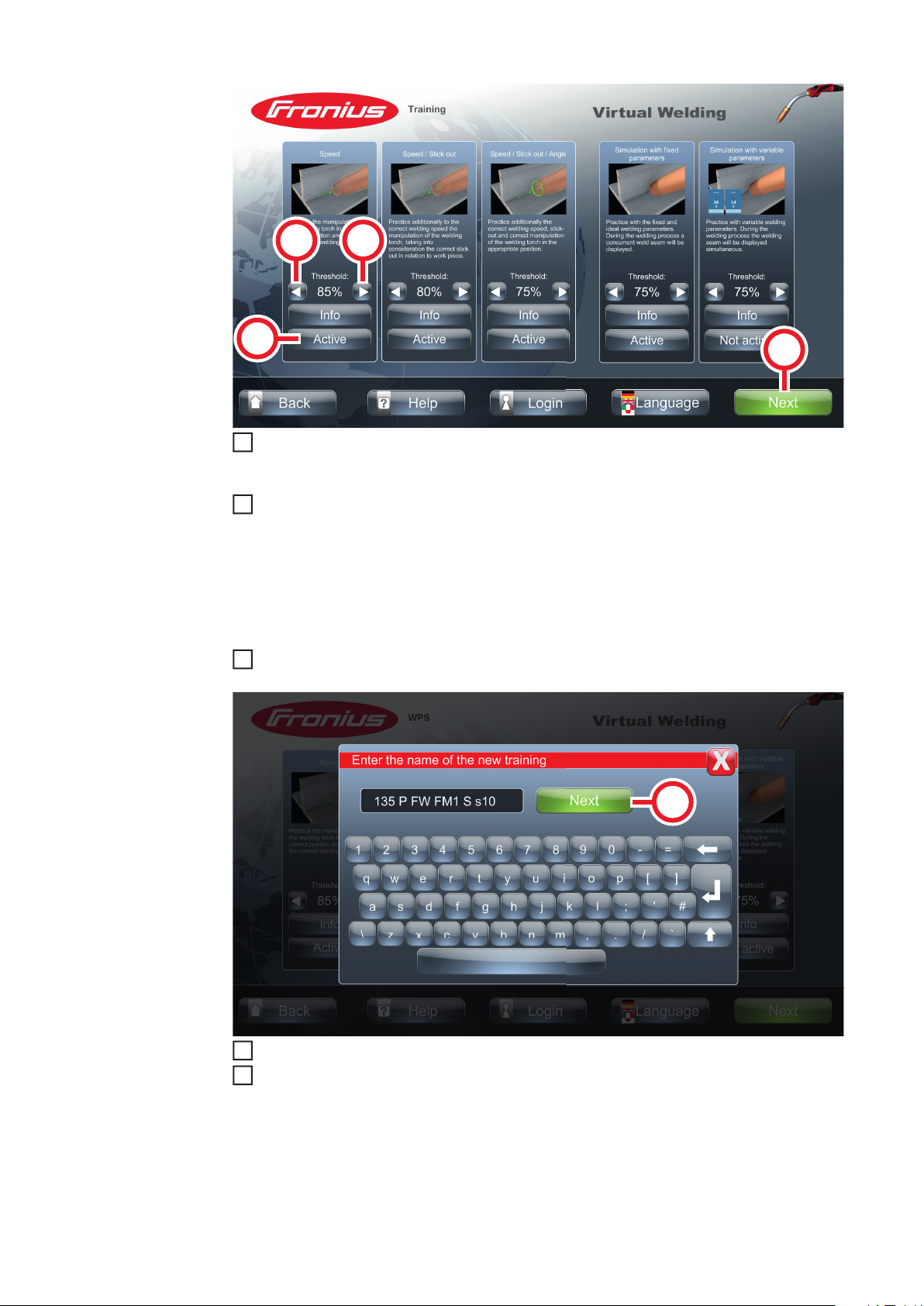
Add training content to the first chapter:
(Only possible if this content type was selected when the chapter was created)
EN
Use the arrow keys to make the desired settings
6
Select button (11)
57
(13)
10
11
(13)
(12)
Enable/disable the required tasks using the buttons (12)
8
- If a task is enabled, it can be disabled again when the course is created
- If a task is disabled, it will not be possible to later enable the task in this curriculum
Use the arrow keys (13) to select the extent of the permissible deviation (Ghost) (for
9
more details on the Ghost see section Ghost from page 69)
- The acceptable deviation can be set in a range of 60-90%
- 60% = Execution of the task may deviate by a maximum of 30% from the
Ghost to be evaluated positively
- 90% = Task must be executed exactly as specified by Ghost to be evaluated
positively
- The acceptable deviations can be edited again when the course is created
Select button (14)
(14)
(15)
Give this training content a name
Select button (15)
12
Add a WPS to the first chapter:
(Only possible if this content type was selected when the chapter was created)
58

(17)
(6)
(7)
16
(16)
Make sure the correct welding process is selected
13
- If necessary, select button (16) to change the welding process
Select button (17) to insert the desired WPS into the chapter
14
Add theory content to the first chapter:
(Only possible if this content type was selected when creating the chapter)
EN
Make sure the correct welding process is selected
15
- If necessary, select button (6) to change the welding process
Select button (7) to insert the desired theory content into the chapter
- Each chapter can contain only one piece of theory content
Add a knowledge check to the first chapter:
(Only possible if this content type was selected when creating the chapter)
59

(7)
(10)
(8)
(8)
(9)
(9)
20
(6)
Make sure the correct welding process is selected
17
- If necessary, select button (6) to change the welding process
Select button (7) to insert the desired knowledge check into the chapter
18
- Each chapter can contain only one knowledge check
60
Select the percentage of questions that need to be answered correctly in order for the
19
knowledge check to be passed (8)
- A value of 80% or more is recommended
- The settings can be adjusted again when the course is created
Set how much time will be allowed to answer a question (9)
- About 30 seconds per question is recommended
Select button (10)
21
Give the chapter a name:
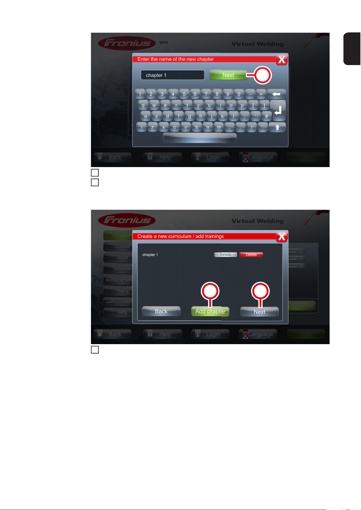
Give this chapter a name
(19)(20)
22
Select button (18)
23
Complete the curriculum:
EN
(18)
Select button (19) to complete and create the curriculum
24
- If you wish, a new chapter can also be added to the curriculum at this point. In this
case, select the button (20) and repeat the previous steps
61
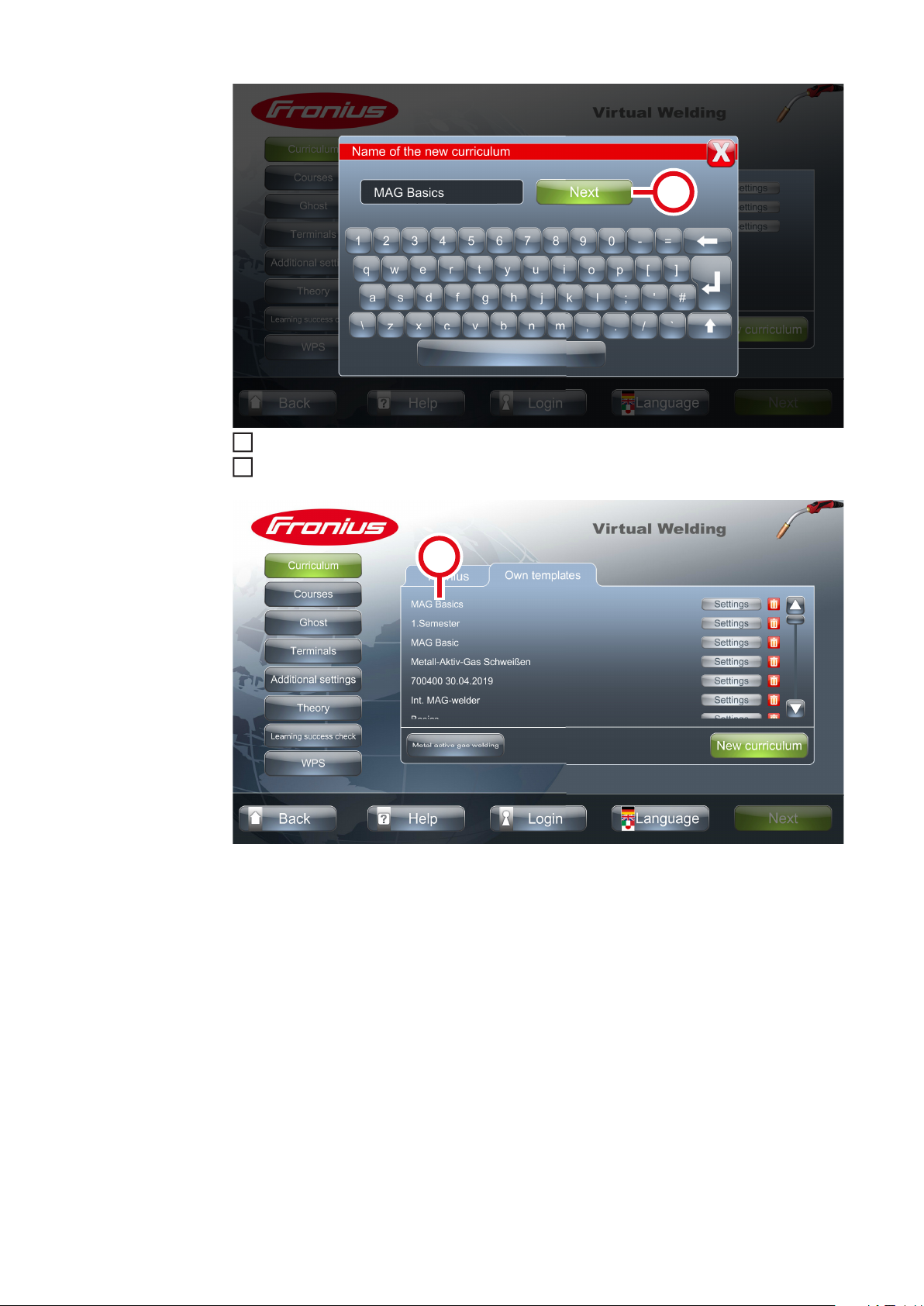
Give the curriculum a name
25
Select button (21)
26
(21)
(22)
62
- The new curriculum is displayed in the overview (22)
Second step of commissioning: creating a course
3
Uses of a course - Individual courses can be compiled for the desired group of trainees from the curricu-
lum
- If there are multiple Virtual Welding systems in a network, the courses can be as-
signed to different Virtual Welding systems, such as:
- Course A is assigned to the systems used for basic training
- Course B is assigned to the systems used for advanced training
EN
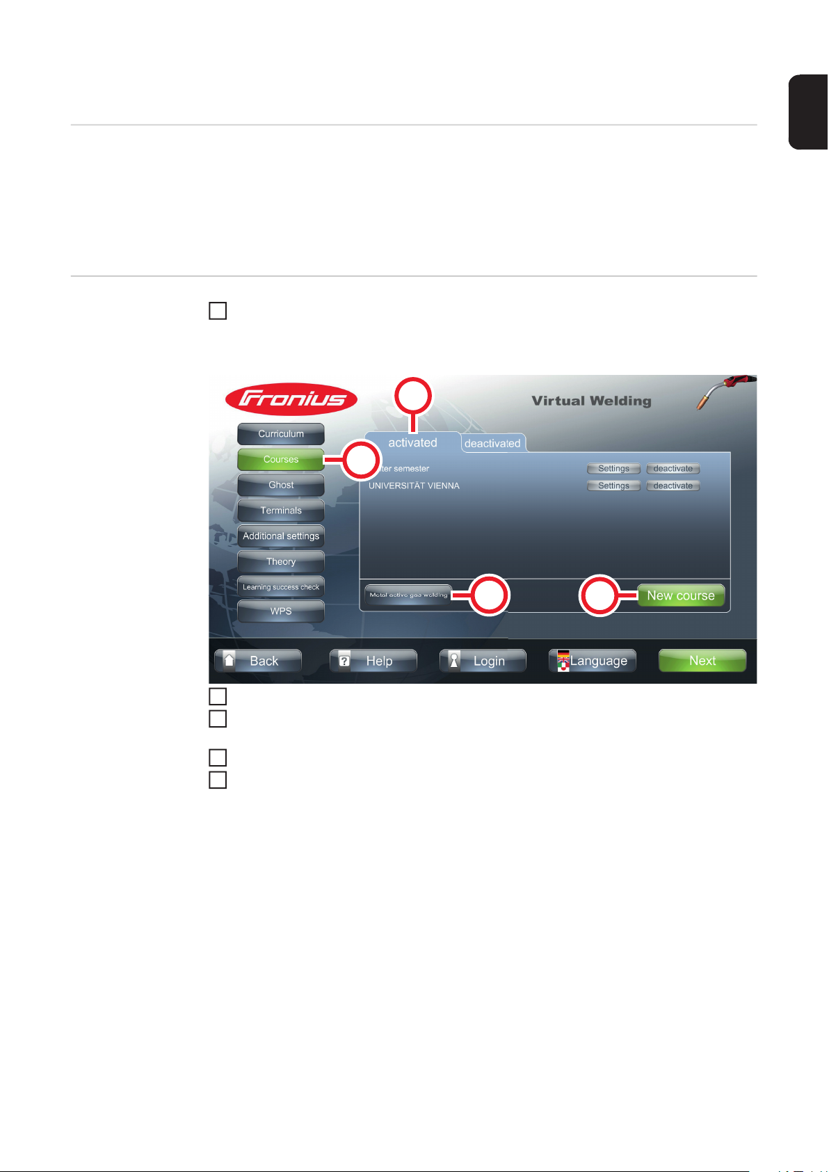
Creating a course Touch the NFC key on the Virtual Welding system sensor to open terminal manage-
1
ment
- For the sensor location, see section Touchscreen and sensor on page 23
(3)
(1)
(2)
Select button (1)
2
Make sure the correct welding process is selected
- If necessary, select button (2) to change the welding process
Select tab (3)
4
Select button (4)
5
(4)
63

(7) (8)
7
8
(9)
(6)
Make sure the correct welding process is selected
6
- If necessary, select button (6) to change the welding process
Select a curriculum to use as the basis for the course. For example (9)
- Fronius curricula are displayed on tab (7)
- Self-created curricula are displayed on tab (8)
(10)
(12)
Select the content you want to add to the course (10)
- Using the Settings button (11):
- Tasks in the curriculum can be disabled
- Acceptable deviations of the tasks can be set
- Acceptable deviations and time limits for the knowledge check can be set
Select button (12)
9
(11)
64
(13)
11
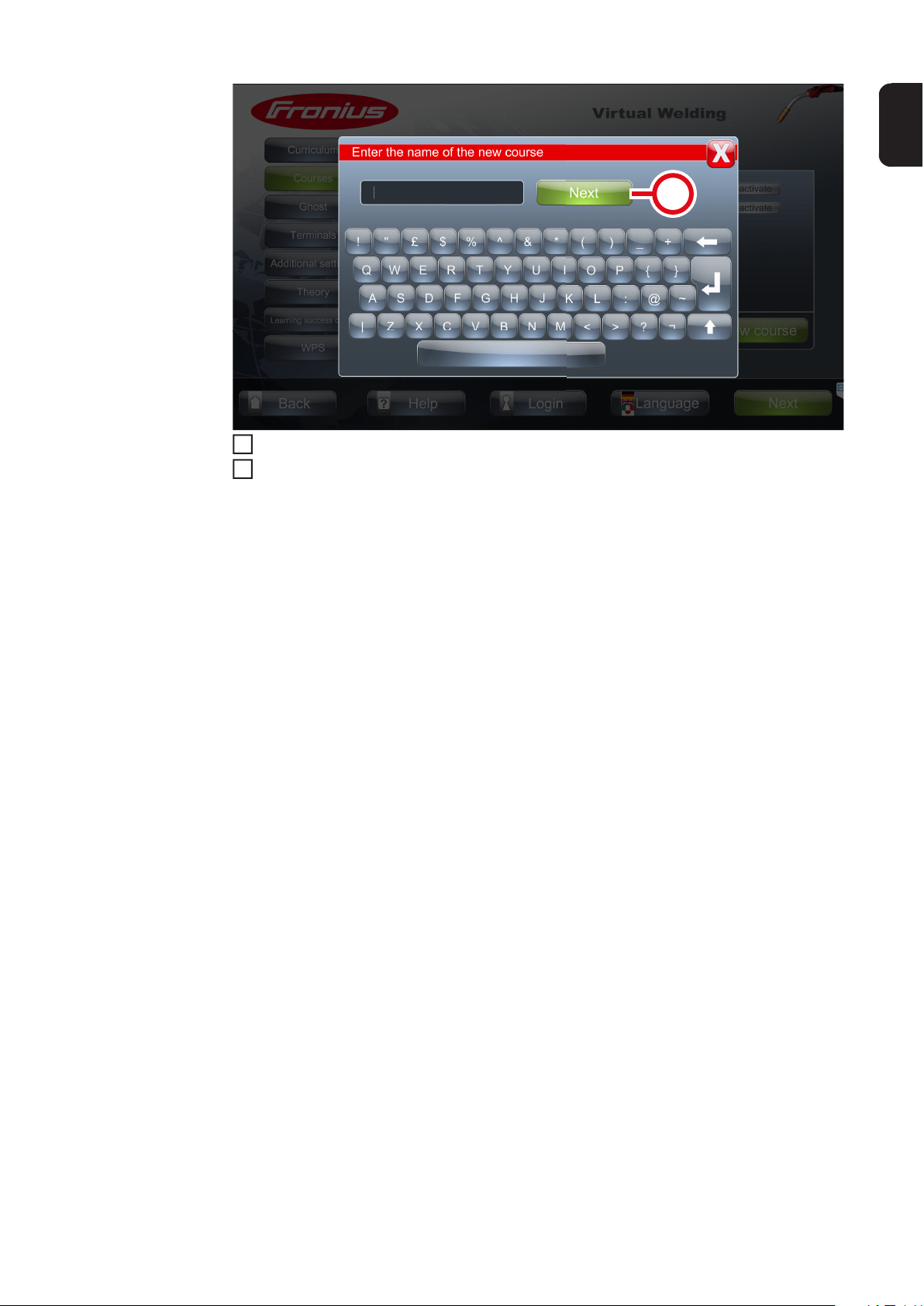
Give the course a name
10
Select button (13)
- The new course is now shown in the course overview
After creating all the courses you want, it is recommended that you back up your data. For
more details on this, see section Creating a backup (exporting data) from page 112.
EN
65

Third step of commissioning: assigning courses
1
2
(4)
(5)
5
Assigning courses to the Virtual
Welding system
Touch the NFC key on the Virtual Welding system sensor to open terminal management
- For the sensor location, see section Touchscreen and sensor on page 23
(1)
(2) (3)
Select button (1)
- Available terminals are displayed (2)
- If there is only one terminal on the network, the serial number is displayed as the
terminal name
Select button (3)
3
Make sure the correct welding process is selected
4
- If necessary, select button (4) to change the welding process
Select the course to be available on the previously selected terminal
- For example (5)
66

(6)
Select button (6)
6
- The course has been assigned to the terminal
EN
Assigning courses to multiple terminals
- If multiple Virtual Welding systems are being used, it is possible to combine them into
groups (cluster networking)
- See section Creating a cluster network from page 108 for a description of how to
create groups
- Courses are assigned to groups as described in the section above
67
Fourth step of commissioning: activating course
2
5
2
mode, preparing the system for users
Activating course
mode
Touch the NFC key on the Virtual Welding system sensor to open terminal manage-
1
ment
- For the sensor location, see section Touchscreen and sensor on page 23
(2)
(3)
(1)
(4)
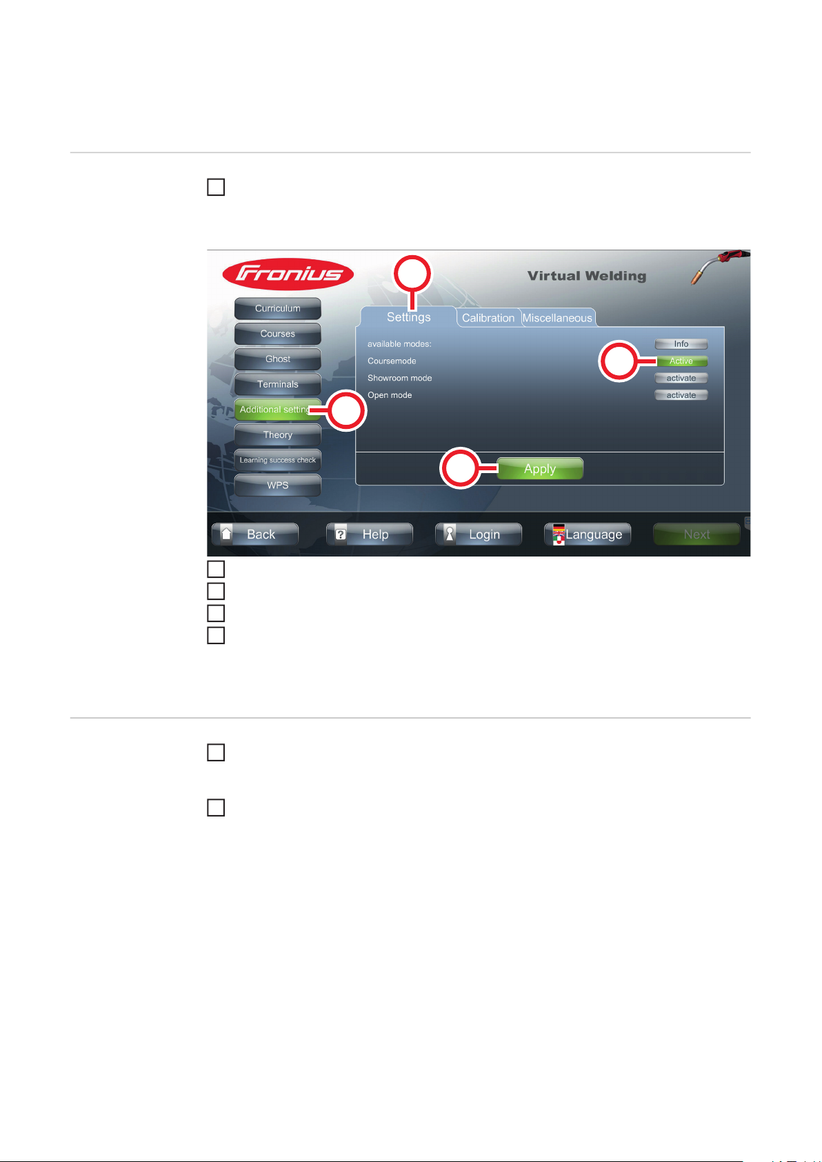
Select button (1)
Select tab (2)
3
Select button (3) to activate course mode
4
Select button (4) to save the entries
- The system is now fully set up
- Refer to the following section for the necessary settings to allow users to begin
the exercises
Preparing the
system for users
68
Create a profile
1
- Either each user creates their own profile, or
- The trainer creates the profiles for all users
User logs on to the system (performed by the users themselves)
- The practical exercises can now be started (read through theory content, com-
plete knowledge checks, complete welding tasks)

Ghost

Explanation and configuration options
2
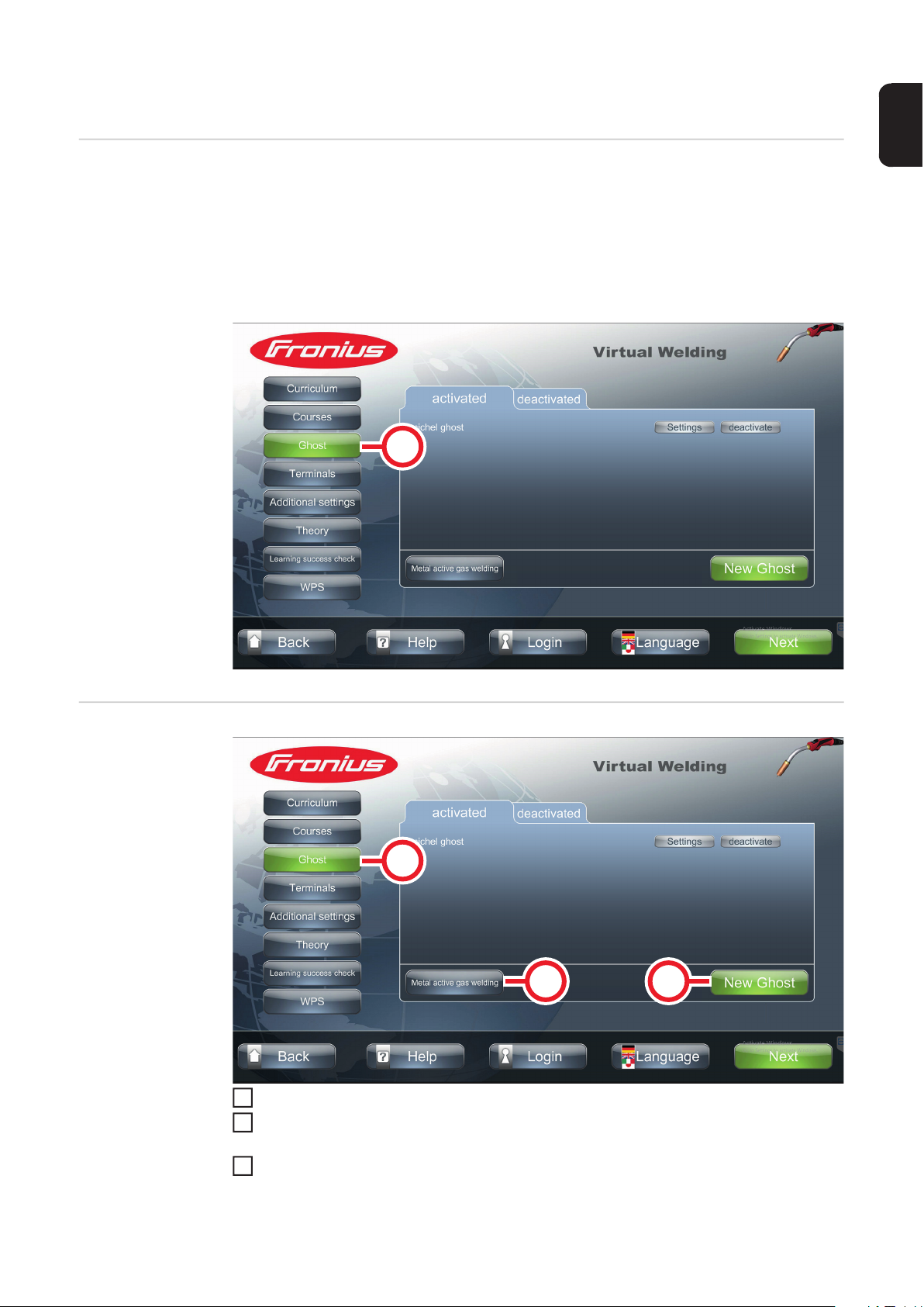
Explanation - The Ghost is a virtual welding torch that is displayed during the welding tasks
- The Ghost shows the ideal movement when welding
- A Ghost is saved for all welding tasks as standard (default Ghost)
- The New Ghost button (1) allows you to create what is known as a variable Ghost
- A variableGhost can be created in addition to the default Ghost and adapted to your
own requirements
- A variable Ghost can be created for all welding processes
(1)
EN
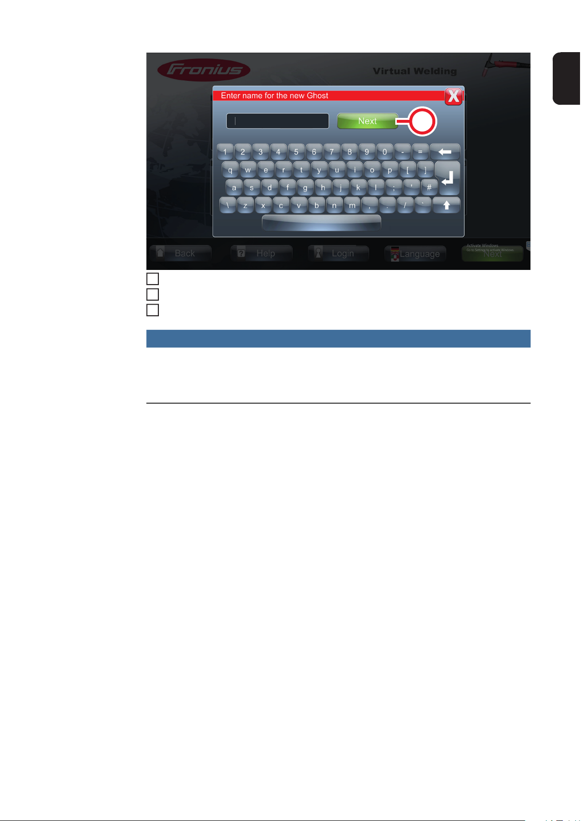
Creating a variable Ghost
(1)
(2)
Select button (1)
1
Make sure the correct welding process is selected
- If necessary, select button (2) to change the welding process
Select button (3)
3
(3)
71

Use the arrow keys to make the desired settings
5
6
4
Select button (4)
(4)
(5)
Select button (5)
72
(6)
9
Enter a name for the variable Ghost
7
Select button (6)
8
Follow the instructions on the touchscreen
NOTE!
With Virtual Welding Robotics, a distinction is made between Polygon and Cycles
when creating a Ghost:
► Polygon: Enables a completely free path to be traced (inscription, etc.)
► Cycles: Equivalent to conventional welding
EN
73

74

Available modes on the Virtual Weld-
ing system

Course mode
2
5
Explanation In course mode, courses with varying degrees of difficulty can easily be configured or
adapted to individual requirements. The courses and the curricula on which they are based
are easy to access. The results can be compared with the help of ranking lists, so that it is
possible to address the precise needs of the trainee welder.
The course mode is used for training:
- Different courses can be assigned to individual terminals
- The results of each user can be compared in ranking lists
- For more details, see section Description of rankings lists, exporting course
data from page 80
- For more details on creating users, see section Profile from page 78
In course mode, the following functions are available:
- Training (practical welding tasks)
- Theory (learning content)
- Knowledge check (testing the knowledge learned)
- Rankings list - for more details, see Description of rankings lists, exporting course
data from page 80
- Profile - for more details, see Profile from page 78
EN
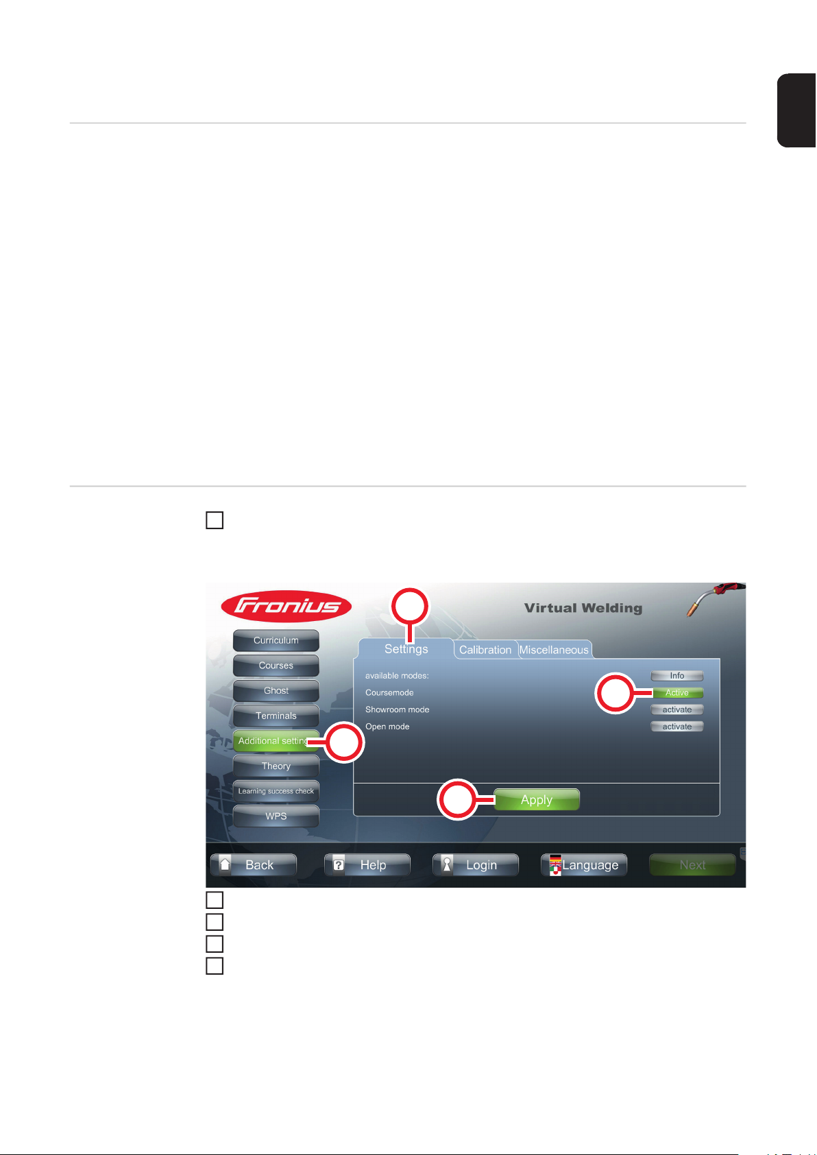
Activating course
mode
Touch the NFC key on the Virtual Welding system sensor to open terminal manage-
1
ment
- For the sensor location, see section Touchscreen and sensor on page 23
(2)
(3)
(1)
(4)
Select button (1)
Select tab (2)
3
Select button (3) to activate course mode
4
Select button (4) to save the entries
- The system is now fully set up
- Refer to the following section for the necessary settings to allow users to begin
the exercises
77
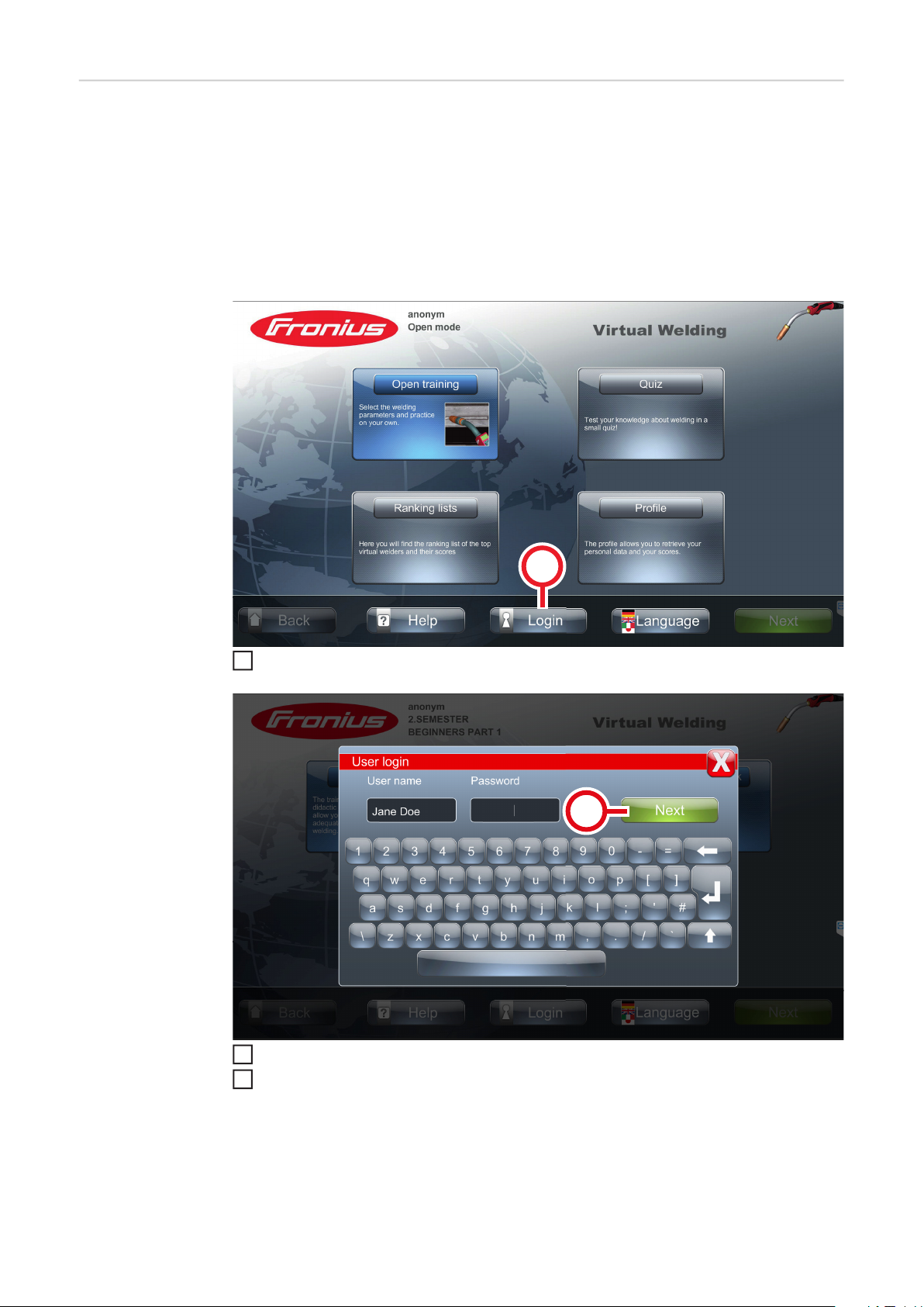
Profile To use the course mode properly, a profile must be created for each user. It is therefore
(1)
3
recommended to create a profile for each user.
A profile allows you to:
- Save data for each user (trainee)
- Follow-up on the latest welding results of each user
- Get an overview of each user via the latest ranking lists
Create a profile:
Select button (1)
1
Enter the name and password
2
Select button (2)
(2)
78
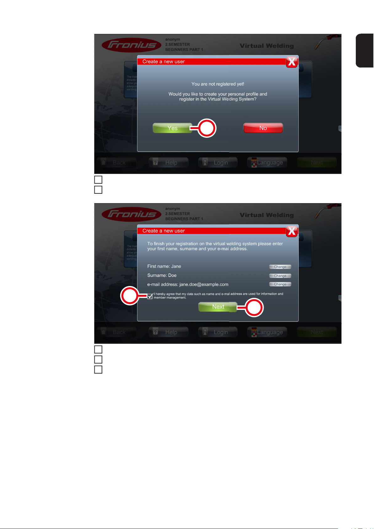
Select button (3)
7
4
Enter required data
5
EN
(3)
(4)
(5)
Read and understand the text next to the checkbox (4) and select the checkbox (4)
6
Select button (5)
Confirm the message displayed
8
79

(6)
Once the settings have been completed, the profile of the respective user can be opened
using button (6)
Description of
rankings lists, exporting course
data
- Each course has its own ranking list
- The ranking lists allow a user's welding results to compared with the welding results
of the other participants (allVirtual Welding systems in the network and their users are
visible in the ranking lists)
- For a user to be listed in the ranking lists, a profile must be created for each user and
the user must be logged in when completing the tasks
- See Profile from page 78
- Ranking lists can be exported with the respective courses
- The export data is only used for viewing/further processing on a PC and cannot
be imported again
- No course content is exported, only course data (students, score, etc.)
To export a course:
Connect a USB flash drive to the USB port of the Virtual Welding system
1
Touch the NFC key on the Virtual Welding system sensor to open terminal manage-
2
ment
- For the sensor location, see section Touchscreen and sensor on page 23
80

(2)
5
(5)
7
EN
(1)
(4)
(3)
Select button (1)
3
Select tab (2)
4
Make sure the correct welding process is selected
- If necessary, select button (3) to change the welding process
Select button (4) next to the desired course
6
Select button (5)
- The course data is stored on the USB flash drive
81
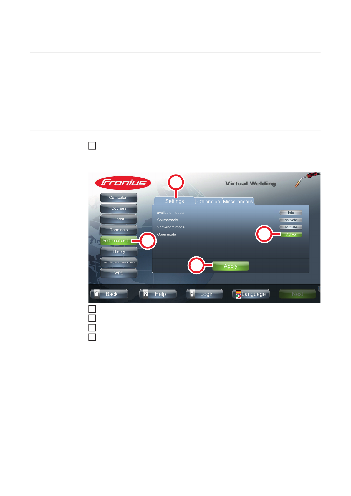
Open mode
3
Explanation - Open mode is used to demonstrate the Virtual Welding system
- All the available welding parameters and exercises can be selected without any training plan
- Scores will not be saved
In open mode, the following functions are available:
- Free training (practical welding tasks)
- Quiz - for more details, see section Quiz from page 99
Enabling open
mode
Touch the NFC key on the Virtual Welding system sensor to open terminal manage-
1
ment
- For the sensor location, see section Touchscreen and sensor on page 23
(2)
(3)
(1)
(4)
Select button (1)
2
Select tab (2)
Select button (3) to enable open mode
4
Select button (4) to save the entries
5
82

Showroom mode
3
Explanation - Showroom mode has the fewest features of any mode, making it ideal for user-free
operation, such as in entrance halls
- Only open training can be selected in showroom mode
EN
Enabling showroom mode
Touch the NFC key on the Virtual Welding system sensor to open terminal manage-
1
ment
- For the sensor location, see section Touchscreen and sensor on page 23
(2)
(3)
(1)
(4)
Select button (1)
2
Select tab (2)
Select button (3) to enable showroom mode
4
Select button (4) to save the entries
5
83

84

Calibration

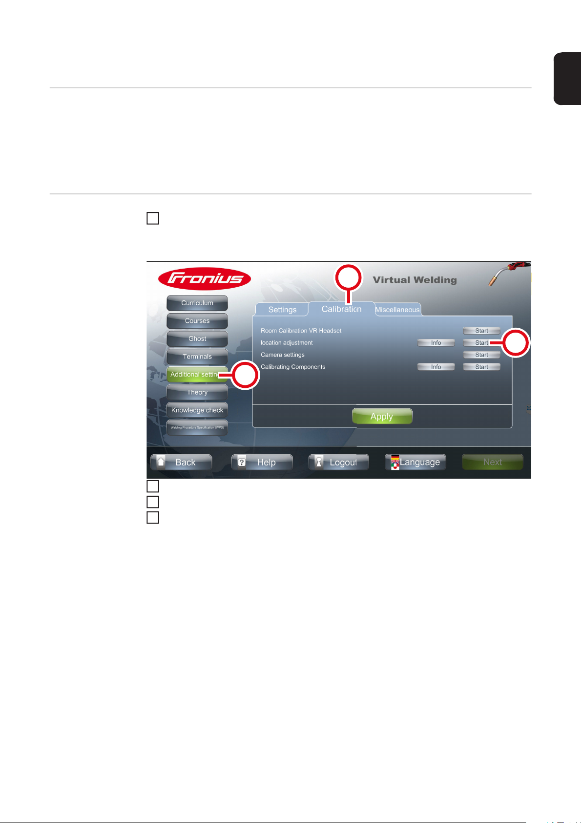
System calibration
(1)
(3)
(2)
3
Function - The system calibration is the calibration of the magnetic sensors in the individual sys-
tem components (workpiece, welding torch, etc.)
- The system calibration compares the positions of the individual components to each
other
- The system calibration must always be carried out when starting for the first time and
when the Virtual Welding system is moved to a different location
EN
Performing system calibration
Touch the NFC key on the Virtual Welding system sensor to open terminal manage-
1
ment
- For the sensor location, see section Touchscreen and sensor on page 23
Select button (1)
2
Select tab (2)
Select button (3)
4
87
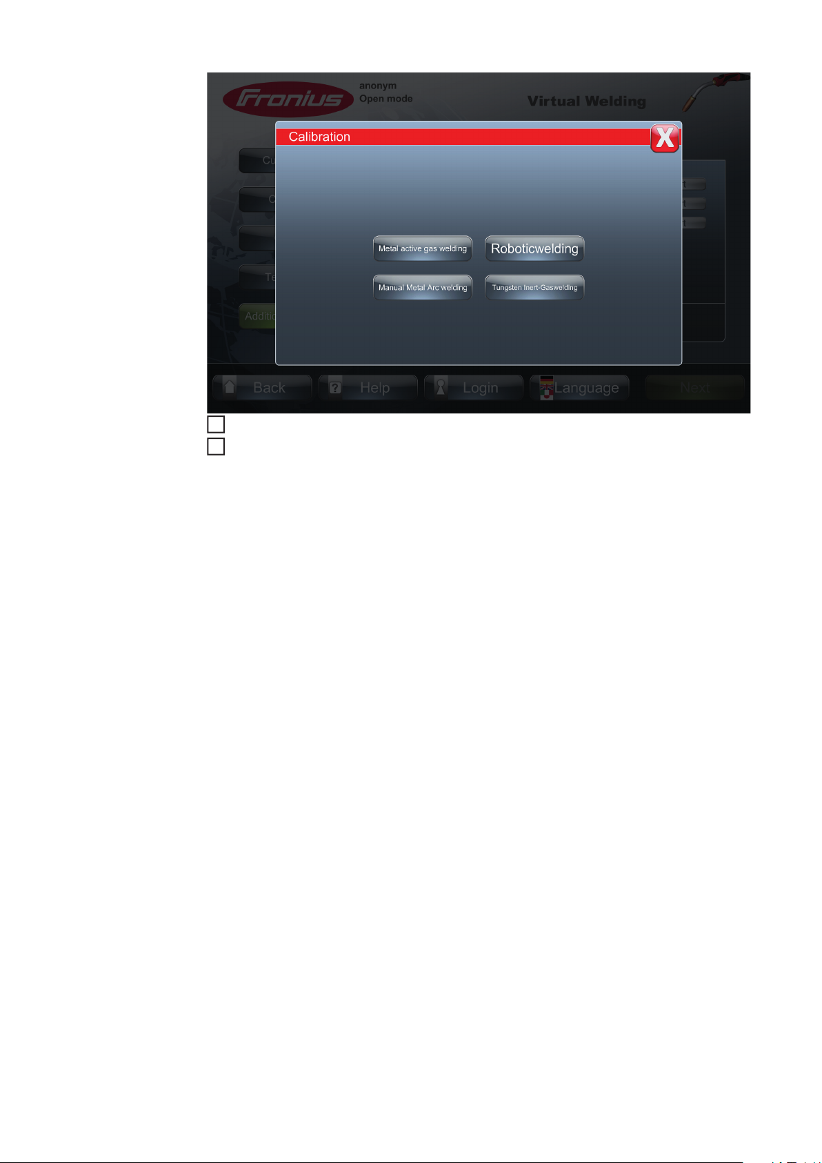
Select the welding process whose system components are to be calibrated
6
5
Follow the instructions on the touchscreen
88

Room calibration
(1) (1)
1
2
Function - Room calibration calibrates the cameras in the 3D glasses (optical calibration)
- The room calibration ensures that the 3D glasses function properly
- The room calibration must always be carried out when starting for the first time and
when the Virtual Welding system is moved to a different location
EN
Performing room
calibration
NOTE!
Risk from optical sources of interference.
These can affect the quality of the calibration.
► During calibration, shield the unit as much as possible from sunlight, spotlights and the
like.
Make sure that the cameras (1) of the
3D glasses are clean and not covered
(by hair, caps, hands, etc.)
Front view of 3D glasses
Touch the NFC key on the Virtual Welding system sensor to open terminal management
- For the sensor location, see section Touchscreen and sensor on page 23
(3)
(4)
(2)
89

Select button (2)
5
3
Select tab (3)
4
Select button (4)
Follow the instructions on the touchscreen / in the glasses
6
90

Component calibration
2
5
Function - The component calibration compares the data of the system calibration (= calibration
of magnetic sensors) and the room calibration (= calibration of the cameras of the 3D
glasses)
- Component calibration is started automatically before each training session
EN
Performing component calibration
Touch the NFC key on the Virtual Welding system sensor to open terminal manage-
1
ment
- For the sensor location, see section Touchscreen and sensor on page 23
(2)
(1)
(3)
Select button (1)
Select tab (2)
3
Select button (3)
4
Select the welding process whose system components are to be calibrated
91

Follow the instructions on the touchscreen
6
92
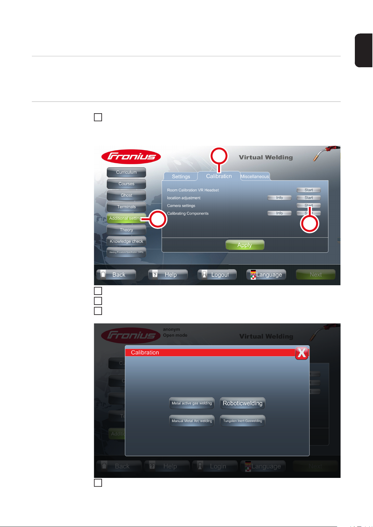
Changing the camera settings
2
5
Function - The camera setting is used to adjust the zoom factor
- Depending on your preferences, this setting can be used to move the displayed image
closer or farther away
EN
Changing the
camera settings
Touch the NFC key on the Virtual Welding system sensor to open terminal manage-
1
ment
- For the sensor location, see section Touchscreen and sensor on page 23
(2)
Select button (1)
Select tab (2)
3
Select button (3)
4
(1)
(3)
Select the desired welding process
93

Follow the on-screen instructions
6
94

Additional settings


Licence management
341
4
Function System-relevant information, such as the following, are shown in the Licensemanager ar-
ea:
- Hardware dongle serial number
- Installed licences
- etc.
Additional Virtual Welding licences, such as licences to enable additional welding processes, can also be installed here.
EN
Opening licence
management (Licensemanager)
Touch the NFC key on the Virtual Welding system sensor to open terminal manage-
1
ment
- For the sensor location, see section Touchscreen and sensor on page 23
(2)
(3)
(1)
Select button (1)
2
Select tab (2)
Select button (3)
- Licence information is displayed
Installing a licence
Once a new licence has been purchased, it will be sent to the customer by the specialist
dealer.
Save the new licence to a USB flash drive
Connect the USB flash drive to the USB port of the Virtual Welding system
2
Open Licensemanager (see previous section)
3
Confirm the message displayed
- This will install and activate the new licence
97

Changing the robot manufacturer
1
4
5
Description The robot manufacturer can be set with a corresponding licence. This shows the arm of the
respective robot manufacturer during robotic welding.
Touch the NFC key on the Virtual Welding system sensor to open terminal management
- For the sensor location, see section Touchscreen and sensor on page 23
(2)
(1)
(3)
Select button (1)
2
Select tab (2)
3
Select button (3)
Select the desired robot manufacturer
98

Quiz
3
2
Function - The quiz is a playful knowledge check, the results are not saved
- The quiz is only available in open mode
- For more details on open mode, see section 82 on page 82
- The system is supplied with a 70-question quiz as standard
EN
Enabling/disabling or importing/exporting
quizzes
Touch the NFC key on the Virtual Welding system sensor to open terminal manage-
1
ment
- For the sensor location, see section Touchscreen and sensor on page 23
(2)
(3)
(4)
(1)
(5)
Select button (1)
2
Select tab (2)
Select button (3) - (5)
4
- Select button (3) to enable/disable the quiz function
- Select button (4) to enable another quiz
- Select button (5) to import or export a quiz
Exporting a quiz Connect a USB flash drive to the USB port of the Virtual Welding system
1
Touch the NFC key on the Virtual Welding system sensor to open terminal management
- For the sensor location, see section Touchscreen and sensor on page 23
99

(2)
5
7
2
Select button (1)
3
Select tab (2)
4
Select button (3)
(1)
(3)
(4)
(5)
(6)
Select tab (4)
6
Select button (5) to export the pre-installed quiz
Select button (6) to export individual/own segments
8
Creating a quiz Connect a USB flash drive configured for Virtual Welding to a PC
100
1
- For instructions on how to configure a USB flash drive, see section Configuring
a USB flash drive from page 48
Open the USB flash drive on the PC
Open "QuizEditor.exe"
3
 Loading...