

Page 1

Fronius prints on elemental chlorine free paper (ECF) sourced from certified sustainable forests (FSC).
/ Perfect Charging / Perfect Welding / Solar Energy
Print LPT 20
LPT 20 board
Installationsanleitung
DEENFR
Diverses
Installations instructions
Miscellaneous
Instructions d'installation
Divers
42,0410,0794 002-16042020
Page 2

2
Page 3
Installation
211
DE
Sicherheit
WARNUNG!
Gefahr durch Fehlbedienung und fehlerhaft durchgeführte Arbeiten.
Schwerwiegende Personen- und Sachschäden können die Folgen sein.
► Alle in diesem Dokument beschriebenen Arbeiten und Funktionen dürfen nur von ge-
schultem Fachpersonal ausgeführt werden, wenn folgende Dokumente vollständig ge-
lesen und verstanden wurden:
► dieses Dokument
► sämtliche Dokumente der Systemkomponenten, insbesondere Sicherheitsvorschriften
WARNUNG!
Gefahr durch einen elektrischen Schlag.
Ein elektrischer Schlag kann tödlich sein. Vor Beginn der Arbeiten:
► Netzschalter der Stromquelle in Stellung - O - schalten
► Stromquelle vom Netz trennen
► sicherstellen, dass die Stromquelle bis zum Abschluss aller Arbeiten vom Netz ge-
trennt bleibt
► Nach dem Öffnen des Gerätes mit Hilfe eines geeigneten Messgerätes sicherstellen,
dass elektrisch geladene Bauteile (z.B. Kondensatoren) entladen sind.
WARNUNG!
Schutzbeschaltung ausbauen
Gefahr durch unzureichende Schutzleiter-Verbindung.
Schwerwiegende Personen- und Sachschäden können die Folgen sein.
► Die Gehäuse-Schrauben stellen eine geeignete Schutzleiter-Verbindung für die Er-
dung des Gehäuses dar.
► Die Gehäuse-Schrauben dürfen keinesfalls durch andere Schrauben ohne zuverlässi-
ge Schutzleiter-Verbindung ersetzt werden.
VORSICHT!
Verletzungsgefahr durch heiße Systemkomponenten.
Schwere Verbrühungen können die Folge sein
► Vor Beginn der Arbeiten alle heißen Systemkomponenten auf Zimmertemperatur (+25
°C, +77 °F) abkühlen lassen, beispielsweise: Kühlmittel,wassergekühlte Systemkom-
ponenten, Antriebsmotor des Drahtvorschubes.
Gehäusemantel abmontieren
1
Am Sekundärgleichrichter Schrauben (1) für Schutzbeschaltung lösen (2) (Abb.1)
Schutzbeschaltung einbauen
Print LTP 20 ausbauen
Schutzbeschaltung (2) mittels Schrauben (1) montieren (Abb.1)
Am Frontprint RTP 2F (5), Flachbandstecker abstecken (6) (Abb.2)
3
Page 4

2-polige Molexstecker (7) abstecken (Abb.3)
4
5
8
1
2
3
1
4
5
9
2
2
2
Am Primärgleichrichter abstecken (Abb.4)
3
– Kabel Drehstrom (weiß) (8)
– Kabel Gleichstrom (+) (rot) (9)
– Kabel Gleichstrom (-) (blau) (10)
Am Netzschalter die Netzkabel (11) abmontieren (Abb.4)
Am Print LTP 20 Schrauben (12) und Linsenkopfschraube (13), für Leistungstransis-
toren, lösen (Abb.5)
Befestigungsschraube (14) lösen (Abb.5)
6
Den Kabelbinder (27) an Trafoleitungen (15) und (16) durchtrennen (Abb.5)
7
Trafoleitung (16) aus Stromsensor (17) ausfädeln (Abb.6)
Print LTP 20 abnehmen
9
Leistungstransistoren ausbauen
Leistungstransistoren einbauen
EPROM ausbauen
Schrauben (18) lösen (Abb.7)
Leistungstransistoren (19) abnehmen
2
Kühlkörper mittels Kontaktspray und nicht faserndem Tuch reinigen
1
An der Unterseite der Leistungstransistoren
– Wärmeleitpaste dünn und gleichmäßig auftragen
Leistungstransistoren (19) seitenrichtig auf den Kühlkörper aufsetzen
– WICHTIG! Beim Aufsetzen der Leistungstransistoren (19) darauf achten, daß die
U-förmigen Ausnehmungen (30) gemäß Abb.7 ausgerichtet sind.
Bedienpanel abmontieren
Am Frontprint RTP 2F (5) Molexstecker (20) abstecken (Abb.8)
2
An den Drehknöpfen (21) und (22) Abdeckungen abnehmen (Abb.9)
3
Befestigungsmuttern (23) für die Drehknöpfe (21) und (22) lösen
– mittels Steckschlüssel (SW10)
Drehknöpfe (21) und (22) abnehmen
Rändelmuttern (24) lösen (Abb.10)
6
– mittels Rändelmutternschlüssel bzw. Spitzzange
Vier Kunststoffdistanzen (25) lösen (Abb.8)
7
Frontprint RTP 2F abnehmen
8
EPROM (28) vorsichtig aus dem Sockel heben (Abb.11)
EPROM einbauen Kontakte im EPROM-Sockel reinigen
Spritzwasserschutz einbauen
4
1
EPROM (28) vorsichtig in den Sockel einsetzen (Abb.11)
Frontprint RTP 2F auf die Distanzen am Bedienpanel aufsetzen
3
Den Spritzwasserschutz (26) auf die Distanzen am Bedienpanel aufsetzen (Abb.12)
1
Vier Kunststoffdistanzen (25) festschrauben (Abb.8)
Page 5

Rändelmuttern nur leicht festschrauben, die Potentiometer können sonst beschädigt
6
7
4
5
6
8
11
14
3
werden. (Abb.10)
– mittels Rändelmutternschlüssel bzw. Spitzzange
Filzringe aufsetzen
4
Drehknöpfe (21) und (22) positionsrichtig aufsetzen (Abb.9)
5
Befestigungsmuttern (23) mittels Steckschlüssel (SW 10) festschrauben
Abdeckungen für Drehknöpfe aufsetzen
Am Frontprint RTP 2F Molexstecker (20) anstecken (Abb.8)
8
Bedienpanel von außen in das Gehäuse einsetzen und montieren
9
DE
Print LPT 20 einbauen
Print LTP 20 auf die Leistungstransistoren (19) und die Messingdistanz (31) aufsetzen
1
(Abb.7)
– darauf achten, daß das Kabel Thermofühler (29) oberhalb des Prints LTP 20 ver-
läuft (Abb.13).
Trafoleitungen (15) und (16) einfädeln (Abb.6)
2
Trafoleitung (16) durch Stromsensor (17) führen (Abb.6)
3
Befestigungsschraube (14), für Print LTP 20, lose andrehen (Abb.5)
– Die Schrauben zwar fest anschrauben, maximal aber mit ca. 2 Nm. Bei stärkerem
Anzugsmoment können die Leistungstransistoren beschädigt werden
Trafoleitung (15) befestigen
– mittels Schraube (12) (Abb.5)
Übrige Befestigungsschrauben (12) festschrauben
Beim Einsetzen der Klemme für Schraube (13) (Abb.5)
7
– Klemme linksseitig in die Vertiefung einsetzen
– Trafoleitung (16) rechtsseitig einschieben
Beilagscheibe und Fächerscheibe aufsetzen
Schraube (13) festschrauben
9
Befestigungsschraube (14) festschrauben (Abb.5)
10
Am Netzschalter die Netzkabel (11) montieren (Abb.4)
Am Primärgleichrichter anstecken (Abb.4)
12
– 3-phasiges Kabel Drehstrom (weiß) (8)
– Kabel Gleichstrom (+) (rot) (9)
– Kabel Gleichstrom (-) (blau) (10)
2-polige Molexstecker (7) anstecken (Abb.3)
13
Am Frontprint RTP 2F (5) Flachbandstecker (6) anstecken (Abb.2)
Kabel mit Kabelbindern befestigen
15
Gehäusemantel montieren
16
5
Page 6

Übersicht
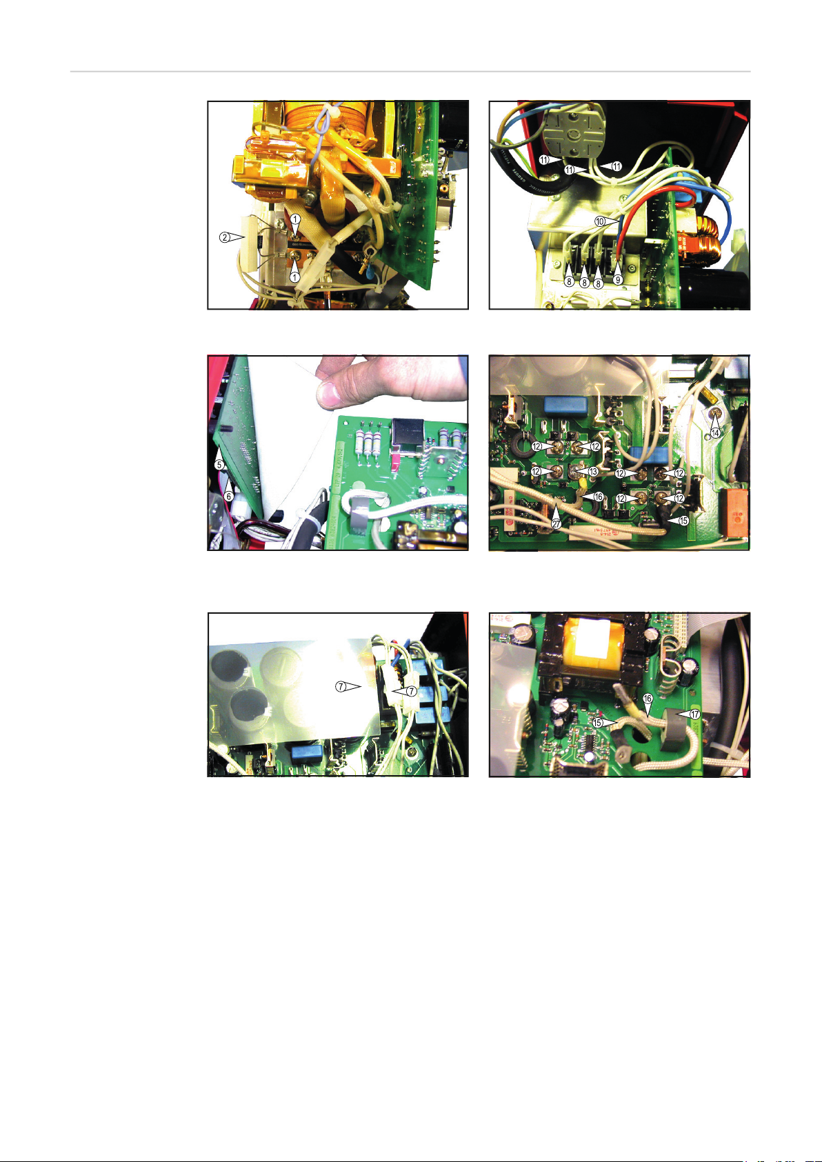
Abb.1 Schutzbeschaltungen ausbauen Abb.4 Kabel am Primärgleichrichter abstecken
Abb.2 Flachbandstecker am Frontprint RTP 2F abstecken
Abb.3 Molexstecker abstecken
Abb.5 Print LTP 20 demontieren
Abb.6 Trafoleitungen ausfädeln
6
Page 7

$
EE5¦QGHOPXWWHUQO¸VHQ $EE(3520DEQHKPHQ
$
DE
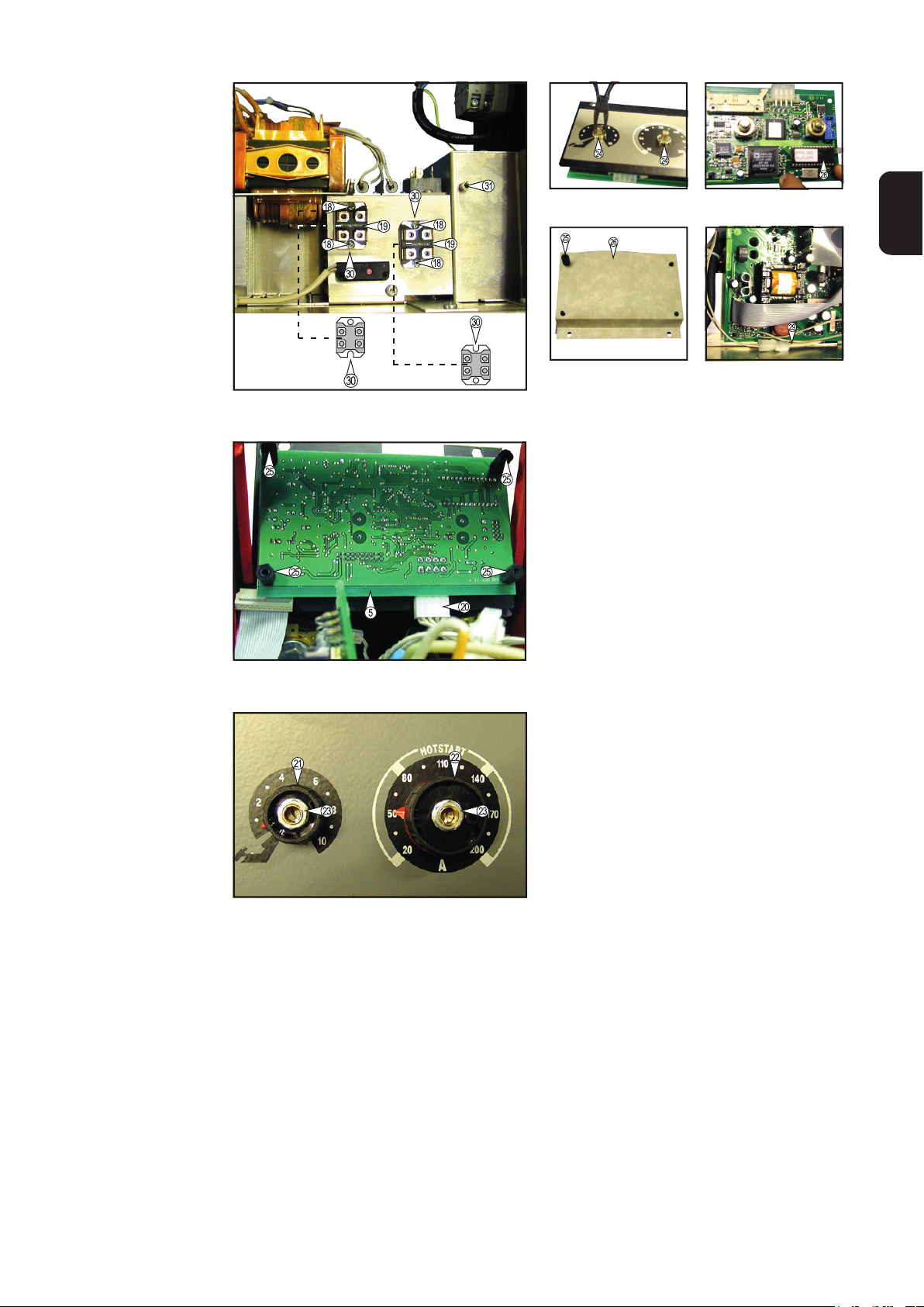
Abb.7 Leistungstransistoren demontieren
Abb.8 Frontprint RTP 2F demontieren
EE6SULW]ZDVVHUVFKXW]
EHIHVWLJHQ
$EE.DEHO7KHUPRI¾KOHU
Abb.9 Drehknöpfe demontieren
7
Page 8

8
Page 9
Installation
2
1
Safety
WARNING!
Danger due to incorrect operation and incorrectly performed work.
This can result in serious injury and damage to property.
► All functions described in this document may only be carried out by trained and quali-
fied personnel after they have fully read and understood the following documents:
► this document
► all documents relating to the system components, especially the safety rules
WARNING!
Risk of electric shock.
An electric shock can be fatal. Before starting work:
► turn the power source mains switch to the "O" position
► disconnect the power source from the mains
► ensure that the power source remains disconnected from the mains until all work has
been completed
► After opening the device, use a suitable measuring instrument to check that electrically
charged components (e.g. capacitors) have been discharged.
WARNING!
EN
Remove the suppressor circuit
Danger from inadequate ground conductor connection.
This can result in serious injury and damage to property.
► The housing screws provide a suitable ground conductor connection for earthing the
housing.
► The housing screws must never be replaced with different screws unless a reliable
ground conductor connection is established.
CAUTION!
Risk of injury from hot system components..
This can result in severe scalds.
► Before starting work, allow all hot system components to cool down to room tempera-
ture (+25°C, +77°F). For example: coolant, water-cooled system components, wire-
feed unit drive motor.
Dismount the housing
1
On the secondary rectifier, loosen the screws (1) for the suppressor circuit (2) (Fig.1)
Fit the suppressor circuit
Remove the LTP
20 printed-circuit
board
Mount the suppressor circuit (2) using the screws (1) (Fig.1)
1
Unplug the ribbon-cable plug (6) from the front board RTP 2F (5) (Fig.2)
Unplug the 2-pole Molex plugs (7) (Fig.3)
2
9
Page 10

Unplug the following from the primary rectifier (Fig.4)
5
6
9
2
3
1
4
5
9
2
2
3
– 3-phase current cable (white) (8)
– DC cable (+) (red) (9)
– DC cable (-) (blue) (10)
Dismount the mains cable (11) from the mains switch (Fig.4)
4
On the LTP 20 p.-c. board, loosen the screws (12) and the cheese-head screw (13),
for power transistors (Fig.5)
Loosen the fixing screw (14) (Fig.5)
Cut through the cable binders (27) around transformer leads (15) and (16) (Fig.5)
7
Unthread the transformer lead (16) from the current sensor (17) (Fig.6)
8
Detach the LTP 20 board
Remove the power transistors
Fit the power
transistors
Remove the
EPROM
Loosen the screws (18) (Fig.7)
1
Detach the power transistors (19)
Clean the heat sink with contact spray and a non-linting cloth
1
Apply the thermolube compound in a uniformly thin layer to the bottoms of the power
2
transistors
Place the power transistors (19) onto the heat sink, the right way round
– IMPORTANT! When placing the power transistors (19) onto the heat sink, make
sure that the U-shaped recesses (30) are aligned as shown in Fig.7.
Dismount the control panel
Unplug the Molex plug (20) from the front board RTP 2F (5) (Fig.8)
2
Remove the covers from dials (21) and (22) (Fig.9)
3
Loosen the fixing nuts (23) for dials (21) and (22)
– for this, use a socket spanner (width across = 10)
Detach dials (21) and (22)
Loosen the knurled nuts (24) (Fig.10)
6
– for this, use a knurled-nut spanner or a pair of pointed pliers
Undo the four plastic spacers (25) (Fig.8)
7
Detach the front board RTP 2F
8
Carefully lift the EPROM (28) out of its base (Fig.11)
Fit the EPROM Clean the contacts in the EPROM base
Fit the splas
guard
10
1
Carefully insert the EPROM (28) into the base (Fig.11)
Place the front board RTP 2F onto the spacers on the control panel
3
Place the splash guard (26) onto the spacers on the control panel (Fig.12)
1
Screw down the four plastic spacers tightly (25) (Fig.8)
Only tighten the knurled nuts (24) gently, otherwise you may damage the potentiom-
3
eters (Fig.10)
– for this, use a knurled-nut spanner or a pair of pointed pliers
Page 11

Place felt rings in position
6
9
4
5
678
11
14
4
Replace dials (21) and (22), in the correct positions (Fig.9)
5
Tighten the fixing nuts (23) with a socket spanner (width across = 10)
Replace the covers for the dials
7
Plug the Molex plug (20) onto the front board RTP 2F (Fig.8)
8
Insert the control panel into the housing from the outside, and mount
EN
Fit the LPT 20
printed-circuit
board
Placing the LTP 20 board onto the power transistors (19) and the brass spacer (31)
1
(Fig.7), make sure that:
– the temperature-sensor cable (29) is routed above the LTP 20 board (Fig.13).
Thread in transformer leads (15) and (16) (Fig.6)
2
Route the transformer lead (16) through the current sensor (17) (Fig.6)
3
Gently turn the fixing screw (14) for the LTP 20 board until it is finger tight only (Fig.5)
– The screws should not be tightened to more than approx. 2 Nm. If greater tight-
ening torque than this is applied, the power transistors may be damaged
Fasten the transformer lead (15)
– with screw (12) (Fig.5)
Tighten the other fixing screws (12)
When inserting the terminal for screw (13) (Fig.5)
– insert the terminal into the left of the recess
– insert the transformer lead (16) into the right of the recess
Put on a washer and serrated-lock washer
Tighten screw (13)
9
Tighten the fixing screw (14) (Fig.5)
10
Mount the mains cable (11) to the mains switch (Fig.4)
Plug the following onto the primary rectifier (Fig.4)
12
– 3-phase current cable (white) (8)
– DC cable(+) (red) (9)
– DC cable(-) (blue) (10)
Plug on the 2-pole Molex plugs (7) (Fig.3)
13
Plug the ribbon-cable plug (6) onto the front board RTP 2F (5) (Fig.2)
Fasten the cables with cable binders
15
Re-mount the housing
16
11
Page 12
Overview
Fig.1 Remove the suppressor circuit Fig.4 Unplug the cables from the primary rectifier
Fig.2 Unplug the ribbon-cable plug from the front
board RTP 2F
Fig.3 Unplug the Molex plugs
Fig.5 Dismount the p.-c. board LTP 20
Fig.6 Unthread the transformer leads
12
Page 13
)LJ/RRVHQWKHNQXUOHG
QXWV
)LJ'HWDFKWKH(3520
EN
Fig.7 Dismount the power transistors
Fig.8 Dismount the front board RTP 2F
)LJ$WWDFKVSODVKJXDUG )LJ7HPSHUDWXUHVHQVRU
FDEOH
Fig.9 Dismount the dials
13
Page 14

14
Page 15
Installation
2
Sécurité
AVERTISSEMENT !
Danger en cas d'erreur de manipulation et d'erreur en cours d'opération.
Cela peut entraîner des dommages corporels et matériels graves.
► Tous les travaux et fonctions décrits dans ce document doivent être effectués par du
personnel spécialisé, uniquement après avoir lu et compris l'intégralité des documents
suivants :
► die présent document
► tous les documents relatifs aux composants du système, en particulier les consignes
de sécurité
AVERTISSEMENT !
Danger en cas de décharge électrique.
Une décharge électrique peut être mortelle. Avant de débuter les travaux :
► Commuter l’interrupteur du secteur de la source de courant sur - O ► Débrancher la prise secteur de la source de courant
► S'assurer que la source de courant demeure débranchée du secteur jusqu'à la fin des
travaux
► Après avoir ouvert l'appareil, s'assurer, à l'aide d'un appareil de mesure approprié, que
les composants à charge électrique (condensateurs par ex.) sont déchargés.
FR
Démonter la protection contre les
surtensions
AVERTISSEMENT !
Danger en cas de connexion insuffisante du conducteur de terre.
Cela peut entraîner des dommages corporels et matériels graves.
► Les vis du boîtier constituent une connexion de conducteur de terre appropriée pour la
mise à la terre du corps de l'appareil.
► Les vis du carter ne doivent en aucun cas être remplacées par d'autres vis qui n'offri-
raient pas ce type de connexion fiable au conducteur de terre.
ATTENTION !
Risque de blessure dû aux composants du système très chauds.
Cela peut entraîner de graves brûlures.
► Avant le début des travaux, laisser refroidir l'ensemble des composants du système
jusqu'à température ambiante (+25 °C, +77 °F), par exemple : le réfrigérant, les com-
posants du système refroidis par eau, le moteur d'entraînement du dévidoir.
Démonter le boîtier
1
Dévisser les vis de la protection contre les surtensions (1) du redresseur secondaire
(2) (fig. 1)
Monter la protection contre les
surtensions
Fixer la protection contre les surtensions (2) avec des vis (1) (fig. 1)
1
15
Page 16

Démonter le Print
3
6
9
2
1
3
8
1
LTP 20
Débrancher le ruban connecteur (6) du Frontprint RTP 2F (5) (fig. 2)
1
Débrancher les connecteurs Molex bipolaires (7) (fig. 3)
2
Débrancher du redresseur primaire (fig. 4)
– Câble courant triphasé (blanc) (8)
– Câble courant continu (+) (rouge) (9)
– Câble courant continu (-) (bleu) (10)
Démonter le câble réseau de l’interrupteur principal (11) (fig. 4)
4
Dévisser les vis (12) et la vis à tête cylindrique (13) des transistors de puissance sur
5
le Print LTP 20 (fig. 5)
Dévisser la vis de fixation (14) (fig. 5)
Retirer l’attache-câbles (27) des fils du transformateur (15) et (16) (fig. 5)
7
Sortir le fil du transformateur (16) du capteur de courant (17) (fig. 6)
8
Print LTP 20 abnehmen
Démonter les
transistors de
puissance
Monter les transistors de puissance
Démonter
l‘EPROM
Dévisser les vis (18) (fig. 7)
1
Retirer les transistors de puissance (19)
Nettoyer le radiateur avec un spray pour contacts et un chiffon qui ne pluche pas
Sur la face inférieure des transistors de puissance
2
– appliquer une fine couche régulière de pâte conductrice de chaleur
Placer les transistors de puissance (19) sur le radiateur en les tournant du bon côté
3
– IMPORTANT! Lorsque vous placez les transistors de puissance (19), faitesatten-
tion à ce que les cavités en U (30) soient dirigées comme représentésur la figure
7.
Démonter le panneau de commande
1
Débrancher le connecteur Molex (20) du Frontprint RTP 2F (5) (fig. 8)
2
Enlever les capuchons des boutons (21) et (22) (fig. 9)
Dévisser les écrous de fixation (23) des boutons (21) et (22)
4
– avec une clé à douille (ouverture 10)
Enlever les boutons (21) et (22)
5
Dévisser les écrous moletés (24) (fig. 10)
6
– avec une clé à écrou moleté ou une pince pointue
Dévisser quatre écarteurs en plastique (25) (fig. 8)
7
Retirer le Frontprint RTP 2F
Soulever l’EPROM (28) de son socle avec précaution (fig. 11)
9
Monter l‘EPROM Nettoyer les contacts dans le socle de l’EPROM
Placer l’EPROM (28) dans le socle avec précaution (fig. 11)
2
Placer le Frontprint RTP 2F sur les écarteurs du panneau de commande
3
16
Page 17

Monter la protec-
3
4
7
4
5
6
8
11
14
tion contre les
projections d‘eau
Placer la protection contre les projections d’eau (26) sur les distances du panneau de
1
commande (fig. 12)
Visser les quatre écarteurs en plastique (25) (fig. 8)
2
Serrer légèrement les écrous moletés (24) (fig.10), vous risquez sinon d’endommager
les potentiomètres.
– avec une clé à écrou moleté ou une pince pointue
Placer les rondelles de feutre
Placer les boutons (21) et (22) en les positionnant bien (fig. 9)
5
Visser les écrous de fixation (23) avec une clé à douille (ouverture 10)
6
Placer les bouchons sur les boutons
Brancher le connecteur Molex (20) du Frontprint RTP 2F (fig. 8)
8
Placer et fixer le panneau de commande dans le boîtier de l’extérieur
9
FR
Monter le Print
LPT 20
Placer le Print LTP 20 sur les transistors de puissance (19) et l’écarteur en laiton (31)
1
(fig. 7), faites attention à ce que
– le câble du capteur thermique (29) passe au-dessus du Print LTP 20 (fig. 13).
Insérer les fils du transformateur (15) et (16) (fig. 6)
2
Introduire le fil du transformateur (16) dans le capteur de courant (17) (fig. 6)
3
Tourner légèrement la vis de fixation (14) du Print LTP 20 sans serrer (fig. 5)
– Bien visser les vis (12), mais sans dépasser environ 2 Nm. Si le couple de serrage
est plus élevé, cela peut endommager les transistors de puissance
Fixer le fil du transformateur (15)
– avec la vis (12) (fig. 5)
Fixer les vis de fixation (12) qui restent
Pour placer la pince de la vis (13) (fig. 5)
7
– placer la pince à gauche de la cavité
– insérer le fil du transformateur (16) à droite
Placer une rondelle plate et une rondelle à dents
Serrer la vis (13)
9
Serrer la vis de fixation (14) (fig. 5)
10
Monter le câble réseau sur l’interrupteur principal (11) (fig. 4)
Brancher sur le redresseur primaire (fig. 4)
12
– Câble courant triphasé (blanc) (8)
– Câble courant continu (+) (rouge) (9)
– Câble courant continu (-) (bleu) (10)
Brancher les connecteurs Molex bipolaires (7) (fig.3)
13
Brancher le ruban connecteur (6) du Frontprint RTP 2F (5) (fig. 2)
Fixer les câbles avec des attaches-câbles
15
Monter le boîtier
16
17
Page 18

Aperçu des photos
Fig.1 Démonter les protections contre les surtensions Fig. 4 Débrancher le câble du redresseur primaire
Fig. 2 Débrancher le ruban connecteur du Frontprint
RTP 2F
Fig. 3 Débrancher le connecteur Molex
Fig.5 Démonter le Print LTP 20
Fig. 6 Enlever les fils du transformateur
18
Page 19

)LJ'«YLVVHUOHV«FURXV
PROHW«V
)LJ'HWDFKWKH(3520
FR
Fig.7 Démonter les transistors de puissance
Fig. 8 Démonter le Frontprint RTP 2F
)LJ$WWDFKVSODVKJXDUG )LJ&¤EOHFDSWHXU
WKHUPLTXH
Fig. 9 Démonter les boutons
19
Page 20

FRONIUS INTERNATIONAL GMBH
Froniusstraße 1, A-4643 Pettenbach, Austria
E-Mail: sales@fronius.com
www.fronius.com
Under www.fronius.com/contact you will find the addresses
of all Fronius Sales & Service Partners and locations
 Loading...