


ENA Engineering Recommendation G99/NI
This form should be used by the Manufacturer to demonstrate and declare compliance with the
requirements of EREC G99/NI. The form can be used in a variety of ways as detailed below:
1. To obtain Fully Type Tested status
The Manufacturer can use this form to obtain Fully Type Tested status for a Power
Generating Module by registering this completed form with the Energy Networks Association
(ENA) Type Test Verification Report Register.
2. To obtain Type Tested status for a product
This form can be used by the Manufacturer to obtain Type Tested status for a product which is
used in a Power Generating Module by registering this form with the relevant parts completed
with the Energy Networks Association (ENA) Type Test Verification Report Register.
3. One-off Installation
This form can be used by the Manufacturer or Installer to confirm that the Power Generating
Module has been tested to satisfy all or part of the requirements of this EREC G99/NI. This
form shall be submitted to the DNO as part of the application.
A combination of (2) and (3) can be used as required, together with Form A2-4 where
compliance of the Interface Protection is to be demonstrated on site.
Note:
Within this Form A2-3 the term Power Park Module will be used but its meaning can be
interpreted within Form A2-3 to mean Power Park Module, Generating Unit or Inverter as
appropriate for the context. However, note that compliance shall be demonstrated at the Power
Park Module level.
If the Power Generating Module is Fully Type Tested and registered with the Energy
Networks Association (ENA) Type Test Verification Report Register, the Installation Document
(Form A3-1 or A3-2) should include the Manufacturer’s reference number (the Product ID), and
this form does not need to be submitted.
Where the Power Generating Module is not registered with the ENA Type Test Verification
Report Register or is not Fully Type Tested this form (all or in parts as applicable) needs to be
completed and provided to the DNO, to confirm that the Power Generating Module has been
tested to satisfy all or part of the requirements of this EREC G99/NI.
Manufacturer´s reference number
Tauro Eco 50-3-D
PGM technology
IGBT power modules, transformerless
Manufacturer name
Fronius International GmbH
Adress
Guenter Fronius Str.1
4600 Wels-Thalheim, Austria
Tel
+43-7242-241-0
Fax
+43-7242-241-224
E:mail
pv@fronius.com
Web site
www.fronius.com
Issue 1 2019
R&D - TESTING TR30591 page 1 of 12
FORM A2-3 Compliance Verification Report for Type A Inverter
Connected Power Generating Modules
@BCL@200ACF9E.doc Backup:Tauro Eco General
ENA Engineering Recommendation G99/NI
Registered Capacity
50 kW
Manufacturer compliance declaration. - I certify that all products supplied by the company with the above
Type Tested Manufacturer’s reference number will be manufactured and tested to ensure that they
perform as stated in this document, prior to shipment to site and that no site Modifications are required
to ensure that the product meets all the requirements of EREC G99/NI.
Signed
On behalf of
Fronius International GmbH
Note that testing can be done by the Manufacturer of an individual component or by an external test
house.
Where parts of the testing are carried out by persons or organisations other than the Manufacturer then
that person or organisation shall keep copies of all test records and results supplied to them to verify that
the testing has been carried out by people with sufficient technical competency to carry out the tests.
Issue 1 2019
R&D - TESTING TR30591 page 2 of 12
@BCL@200ACF9E.doc Backup:Tauro Eco General
ENA Engineering Recommendation G99/NI
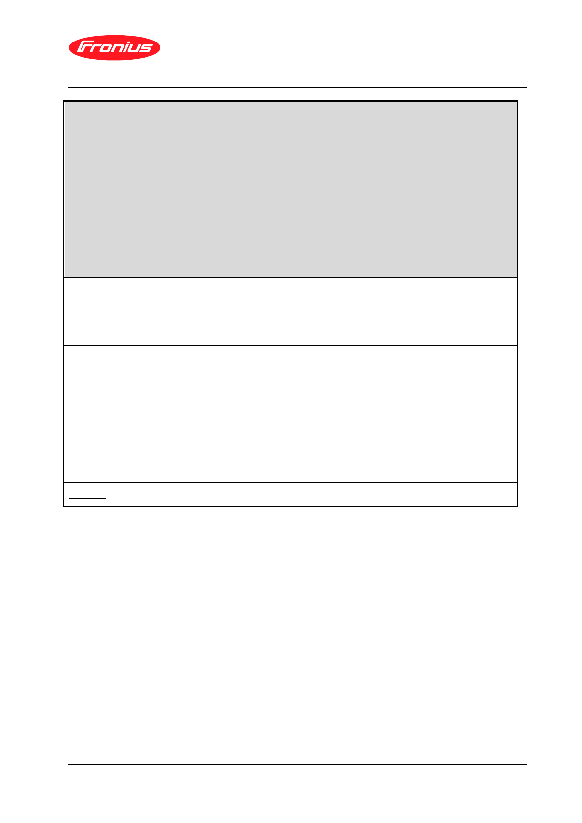
1. Operating Range: Tests should be carried with the Power Generating Module operating at
Registered Capacity and connected to a suitable test supply or grid simulation set. The power
supplied by the primary source shall be kept stable within ± 5 % of the apparent power value set for
the entire duration of each test sequence.
Frequency, voltage and Active Power measurements at the output terminals of the Power
Generating Module shall be recorded every second. The tests will verify that the Power Generating
Module can operate within the required ranges for the specified period of time.
The Interface Protection shall be disabled during the tests.
In case of a PV Power Park Module the PV primary source may be replaced by a DC source.
In case of a full converter Power Park Module (eg wind) the primary source and the prime mover
Inverter/rectifier may be replaced by a DC source.
Test 1
Voltage = 85% of nominal (195.5 V),
Frequency = 47.5 Hz,
Power Factor = 1,
Period of test 90 minutes
Always connected
Test 2
Voltage = 110% of nominal (253 V).,
Frequency = 51.5 Hz,
Power Factor = 1,
Period of test 90 minutes
Always connected
Test 3
Voltage = 110% of nominal (253 V),
Frequency = 52.0 Hz,
Power Factor = 1,
Period of test 15 minutes
Always connected
Remark: During the tests 1, 2 and 3 the unit does not disconnect, tests have been passed.
Issue 1 2019
R&D - TESTING TR30591 page 3 of 12
@BCL@200ACF9E.doc Backup:Tauro Eco General
ENA Engineering Recommendation G99/NI
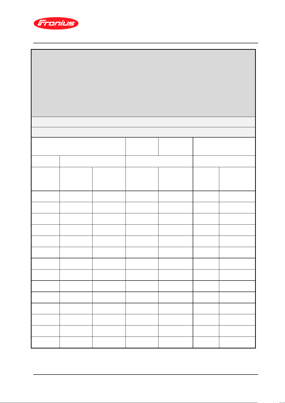
2. Power Quality – Harmonics:
For Power Generating Modules of Registered Capacity of less than 75 A per phase (ie 50 kW) the
test requirements are specified in Annex A.7.1.5. These tests should be carried out as specified in BS
EN 61000-3-12. The results need to comply with the limits of Table 2 of BS EN 61000-3-12 for single
phase equipment and Table 3 of BS EN 610000-3-12 for three phase equipment.
Power Generating Modules with emissions close to the limits laid down in BS EN 61000-3-12 may
require the installation of a transformer between 2 and 4 times the rating of the Power Generating
Module in order to accept the connection to a Distribution Network.
For Power Generating Modules of Registered Capacity of greater than 75 A per phase (ie 50 kW)
the installation shall be designed in accordance with EREC G5.
Power Generating Module tested to BS EN 61000-3-12
Phase 1
Power Generating Module rating per
phase (rpp)
16.6
kVA
Harmonic % = Measured
Value (A) x 23/rating per
phase (kVA)
Harmonic
At 45-55% of Registered
Capacity
100% of Registered
Capacity
Limit in BS EN 61000-3-12
Measured
Value MV in
Amps
%
Measured
Value MV in
Amps
%
1 Phase
3 phase
2
0.074
0.051
0.107
0.075
8%
8%
3
0.237
0.166
0.276
0.192
21.6%
Not stated
4
0.134
0.093
0.120
0.084
4%
4%
5
0.071
0.049
0.100
0.069
10.7%
10.7%
6
0.069
0.048
0.060
0.042
2.67%
2.67%
7
0.173
0.120
0.169
0.118
7.2%
7.2%
8
0.081
0.057
0.084
0.058
2%
2%
9
0.082
0.057
0.064
0.045
3.8%
Not stated
10
0.022
0.015
0.051
0.035
1.6%
1.6%
11
0.248
0.173
0.341
0.238
3.1%
3.1%
12
0.009
0.006
0.013
0.009
1.33%
1.33%
13
0.324
0.226
0.379
0.264
2%
2%
THD20
0.47
0.59
23%
13%
PWHD21
1.38
1.94
23%
22%
Issue 1 2019
R&D - TESTING TR30591 page 4 of 12
20
THD = Total Harmonic Distortion
21
PWHD = Partial Weighted Harmonic Distortion
@BCL@200ACF9E.doc Backup:Tauro Eco General
 Loading...