

Page 1

Fronius prints on elemental chlorine free paper (ECF) sourced from certified sustainable forests (FSC).
/ Perfect Charging / Perfect Welding / Solar Energy
TU Podium
TU Podium
Installationsanleitung
DE
Systemerweiterung
Installation instructions
System extension
EN-US
42,0410,1593 011-19072021
Page 2

Page 3

Inhaltsverzeichnis
Vor der Montage beachten 4
Allgemeines 4
Lieferumfang 4
Montagehinweis 4
Sicherheit 4
Montage 6
Standkonsole am Boden festschrauben 6
Zwei Standkonsolen miteinander verschrauben 6
Montagepositionen der Stromquellen 8
Systemkomponenten auf Standkonsole schrauben 9
Verbindungs-Schlauchpaket konfigurieren 11
Option Radbremse 12
Sicherheit 12
Lieferumfang 12
Radbremse montieren 12
Radbremse auf zwei miteinander verbundene Standkonsolen montieren 13
Option OPT/TU Drehzapfen-Aufnahme Podium 14
OPT/TU Drehzapfen-Aufnahme Podium montieren 14
DE
3
Page 4

Vor der Montage beachten
TPSi, TSt
Allgemeines TU Podium wird nachfolgend immer als Standkonsole bezeichnet.
Lieferumfang
Montagehinweis
Sicherheit
HINWEIS!
Auf der Standkonsole kann nicht montiert werden:
- eine Gasflaschen-Halterung
- OPT/TU Drehzapfen-Aufnahme
Als Ersatz für die OPT/TU Drehzapfen-Aufnahme kann die OPT/TU Drehzapfen-Aufnahme Podium auf der Stromquelle montiert werden.
WARNUNG!
Gefahr durch Fehlbedienung und fehlerhaft durchgeführte Arbeiten.
Schwerwiegende Personen- und Sachschäden können die Folge sein.
Alle in diesem Dokument beschriebenen Arbeiten und Funktionen dürfen nur von
▶
geschultem Fachpersonal ausgeführt werden.
Dieses Dokument lesen und verstehen.
▶
Sämtliche Bedienungsanleitungen der Systemkomponenten, insbesondere Sicher-
▶
heitsvorschriften lesen und verstehen.
WARNUNG!
4
Gefahr durch umstürzende Geräte.
Schwerwiegende Personen- und Sachschäden können die Folge sein.
Die Standkonsole darf nur bis zu einem Neigungswinkel von 10° verwendet werden.
▶
Weist der Untergrund einen Neigungswinkel größer als 10° auf, darf die Standkonsole nicht verwendet werden.
Vor Beginn der Montagearbeiten alle Geräte von der Standkonsole entfernen.
▶
Page 5

WARNUNG!
940 mm
(37.01 inch)
Gefahr durch elektrischen Strom.
Schwere Verletzungen oder Tod können die Folge sein.
Vor Beginn der Arbeiten alle beteiligten Geräte und Komponenten ausschalten und
▶
vom Stromnetz trennen.
Alle beteiligten Geräte und Komponenten gegen Wiedereinschalten sichern.
▶
Maximale Systemhöhe:
WARNUNG!
Gefahr durch umstürzende Geräte.
Schwerwiegende Personen- und
Sachschäden können die Folge sein.
Ab einer Systemhöhe von 940 mm
▶
(37.01 inch) die Standkonsole dauerhaft am Boden festschrauben.
DE
Beim Transport der Standkonsole beachten:
WARNUNG!
Gefahr durch umstürzende Geräte.
Schwerwiegende Personen- und Sachschäden können die Folge sein.
Die Standkonsole nur von der Längsseite auf die Staplergabel aufnehmen.
▶
Maximal 2 miteinander verschraubte Standkonsolen mit dem Stapler transportieren.
▶
5
Page 6

Montage
Standkonsole am
Boden festschrauben
WARNUNG!
Gefahr durch umstürzende Geräte.
Schwerwiegende Personen- und Sachschäden können die Folge sein.
Das Befestigungsmaterial zum Festschrauben der Standkonsole ist nicht im Liefer-
▶
umfang der Standkonsole enthalten. Der Monteur ist für die Auswahl des richtigen
Befestigungsmaterials selbst verantwortlich.
1
Zwei Standkonsolen miteinander verschrauben
Bohrlöcher markieren
2
Standkonsole 16 Mal am Untergrund festschrauben
Standkonsolen nur wie in der nachfolgenden Grafik links dargestellt miteinander verschrauben.
6
Page 7

Standkonsolen mit dem mitgelieferten Befestigungsmaterial wie folgt miteinander verschrauben:
1
DE
7
Page 8

Montagepositio-
(1)
(2)
(3)
(1)
(1)
(2)
(3)
(1)
(2)
(3)(3)
(3)(3)
(2)
(1) (2)(2)
(1)
nen der Stromquellen
(1) TPS/i, TSt
(2) TPS, TT/MW, Acerios
(3) TPS/i - Rackmontage
8
Page 9

Systemkomponenten auf Standkonsole schrauben
WARNUNG!
Gefahr von umstürzenden Geräten durch zu hohen Schwerpunkt.
Schwerwiegende Personen- und Sachschäden können die Folge sein.
Die schwersten Systemkomponenten ganz unten auf der Standkonsole positionieren
▶
und festschrauben
Beispielsweise bei Verwendung einer ToolBox und eines Autotrafos: den Autotrafo
▶
als erstes Gerät auf der Standkonsole montieren, die ToolBox am Autotrafo montieren. Darüber Kühlgerät und Stromquelle montieren.
1
DE
Schrauben aus dem Lieferumfang der Standkonsole verwenden
2
Schrauben aus dem Lieferumfang der Standkonsole verwenden
9
Page 10

3
Schrauben aus dem Lieferumfang des Kühlgerätes verwenden
10
Page 11

Verbindungs-
940 mm
(37.01 inch)
200 mm (7.87 inch)
Schlauchpaket
konfigurieren
Bei Systemen mit einer Höhe von mehr als
740 mm / 29.19 inch (beispielsweise LSCStromquellen mit einem Kühlgerät = Systemhöhe von 940 mm / 37.01 inch) die
Zugentlastung vom VerbindungsSchlauchpaket wie nachfolgen dargestellt
nach hinten verschieben.
DE
1
3
2
11
Page 12

Option Radbremse
940 mm
(37.01 inch)
(1)
(2)
(3)
(4)
(5)
Sicherheit
Lieferumfang
WARNUNG!
Gefahr durch umstürzende Geräte.
Schwerwiegende Personen- und
Sachschäden können die Folge sein.
Ab einer Systemhöhe von 940 mm
▶
(37.01 inch) darf die Option Radbremse nicht verwendet werden.
Ab einer Systemhöhe von 940 mm
▶
(37.01 inch) die Standkonsole dauerhaft am Boden festschrauben.
(1) 2 Lenkrollen
(2) 2 Bockrollen
(3) 16 Sechskant-Schrauben M 8 x 16
mm
(4) 16 Beilagscheiben A 8
(5) 16 Tensilock-Sechskant-Muttern M
8
Radbremse montieren
Artikelnummer der Option Radbremse =
4,100,340
1
12
Page 13

Radbremse auf
zwei miteinander
verbundene
Standkonsolen
montieren
1
DE
13
Page 14
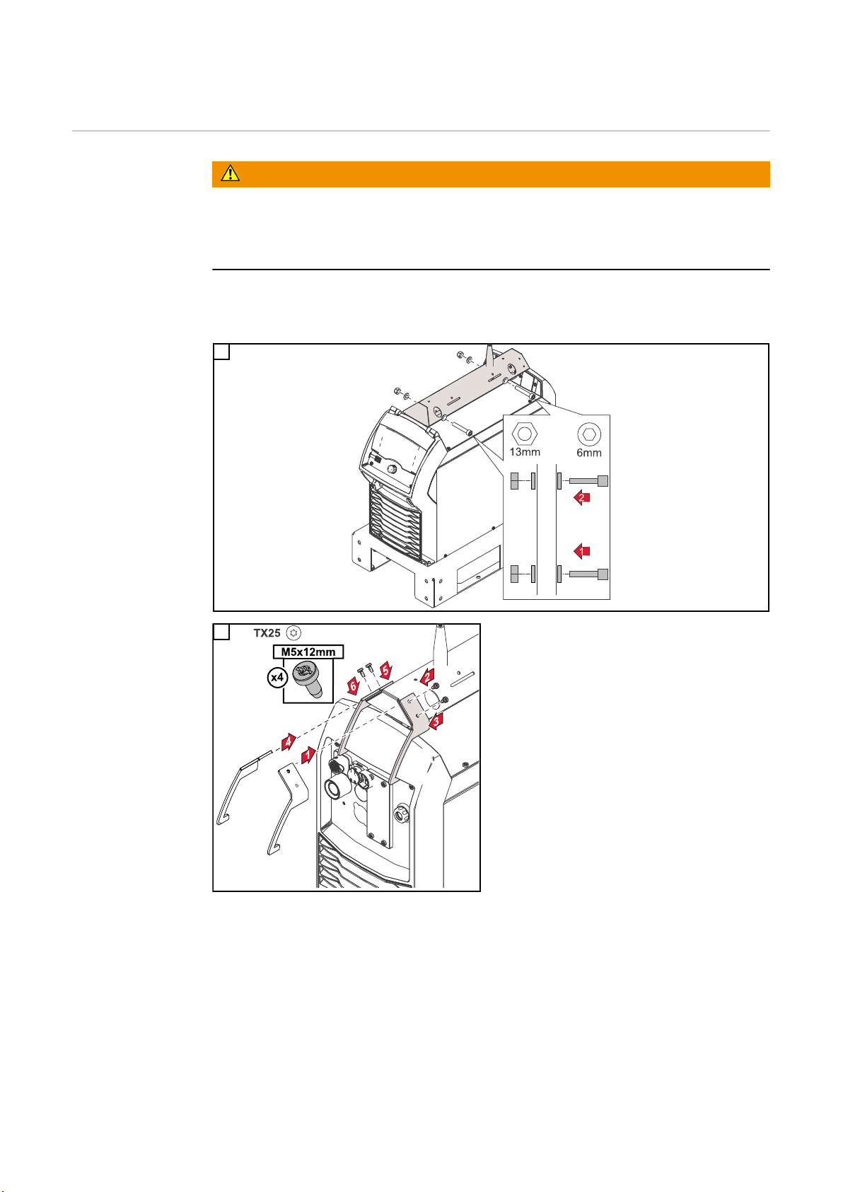
Option OPT/TU Drehzapfen-Aufnahme Podium
OPT/TU Drehzapfen-Aufnahme
Podium montieren
WARNUNG!
Gefahr durch umstürzende Geräte.
Schwerwiegende Personen- und Sachschäden können die Folge sein.
Vor der Montage von OPT/TU Drehzapfen-Aufnahme Podium, die Standkonsole
▶
dauerhaft am Boden festschrauben.
Alle notwendigen Schrauben, Scheiben und Muttern dem Lieferumfang der OPT/TU
Drehzapfen-Aufnahme Podium entnehmen.
1
2
14
Page 15

Table of contents
Observe before installation 16
General 16
Scope of supply 16
Assembly note 16
Safety 16
Installation 18
Screw the upright console to the floor 18
Screw two upright consoles together 18
Mounting positions of the power sources 20
Screw the system components onto the upright console 21
Configuring the interconnecting hosepack 23
Optional wheel brake 24
Safety 24
Scope of supply 24
Mounting the wheel brake 24
Mount wheel brake on two interconnected upright consoles 25
OPT/TU swivel pin holder podium option 26
Mounting the OPT/TU swivel pin holder podium 26
EN-US
15
Page 16

Observe before installation
TPSi, TSt
General TU Podium is always referred to as the upright console in the following.
Scope of supply
Assembly note
Safety
NOTE!
The following cannot be mounted on the upright console:
- Gas cylinder holder
- OPT/TU swivel pin holder
As a replacement for the OPT/TU swivel pin holder, the OPT/TU swivel pin holder
podium can be mounted on the power source.
WARNING!
Danger from incorrect operation and work that is not carried out properly.
This can result in severe personal injury and damage to property.
All the work and functions described in this document must only be carried out by
▶
trained and qualified personnel.
Read and understand this document.
▶
Read and understand all the Operating Instructions for the system components,
▶
especially the safety rules.
WARNING!
16
Danger from falling devices.
This can result in severe personal injury and damage to property.
The upright console may only be used up to a tilt angle of 10°. If the subsurface has
▶
a tilt angle greater than 10°, the upright console must not be used.
Before starting installation work, remove all devices from the upright console.
▶
Page 17

WARNING!
940 mm
(37.01 inch)
Danger from electrical current.
This may result in serious injuries or death.
Before starting work, switch off all the devices and components involved and discon-
▶
nect them from the grid.
Secure all devices and components involved so they cannot be switched back on.
▶
Maximum system height:
WARNING!
Danger from falling devices.
This can result in severe personal injury
and damage to property.
From a system height of 940 mm
▶
(37.01 inches), bolt the upright console permanently to the floor.
EN-US
Observe the following when transporting the upright console:
WARNING!
Danger from falling devices.
This can result in severe personal injury and damage to property.
Only pick up the upright console from the long side on the forklift fork.
▶
Only use the forklift to transport a maximum of 2 upright consoles bolted together.
▶
17
Page 18

Installation
Screw the upright
console to the
floor
WARNING!
Danger from falling devices.
This can result in severe personal injury and damage to property.
The mounting materials for screwing the upright console in place are not included in
▶
the scope of supply for the upright console. The installer is responsible for selecting
the proper mounting materials.
1
Screw two
upright consoles
together
Mark drill holes
2
Screw the upright console to the subsurface with 16 screws
Screw the upright consoles only as shown in the following diagram on the left.
18
Page 19

Screw the upright consoles together with the supplied mounting materials as follows:
1
EN-US
19
Page 20

Mounting positi-
(1)
(2)
(3)
(1)
(1)
(2)
(3)
(1)
(2)
(3)(3)
(3)(3)
(2)
(1) (2)(2)
(1)
ons of the power
sources
(1) TPS/i, TransSteel
(2) TPS, TT/MW, Acerios
(3) TPS/i rack mounting
20
Page 21

Screw the system
components onto
the upright console
WARNING!
Danger of equipment falling over due to high center of gravity.
This can result in severe personal injury and damage to property.
Position the heaviest system components at the very bottom of the upright console
▶
and screw them in place
For example, when using a ToolBox and an auto-transformer: mount the auto-trans-
▶
former as the first device on the upright console, mount the ToolBox on the autotransformer. Mount the cooling unit and power source above it.
1
EN-US
Use screws from the scope of supply of the upright console
2
Use screws from the scope of supply of the upright console
21
Page 22

3
Use screws from the scope of supply of the cooling unit
22
Page 23

Configuring the
940 mm
(37.01 inch)
200 mm (7.87 inch)
interconnecting
hosepack
For systems taller than 740 mm / 29.19
inches (for example, LSC power sources
with a cooling unit = system height of 940
mm / 37.01 inches), move the strain-relief
device of the interconnecting hosepack
backwards as shown below.
EN-US
1
3
2
23
Page 24

Optional wheel brake
940 mm
(37.01 inch)
(1)
(2)
(3)
(4)
(5)
Safety
Scope of supply
WARNING!
Danger from falling devices.
This can result in severe personal injury
and damage to property.
From a system height of 940 mm
▶
(37.01 inches), the wheel brake option
must not be used.
From a system height of 940 mm
▶
(37.01 inches), bolt the upright console permanently to the floor.
(1) 2 swivel casters
(2) 2 fixed casters
(3) 16 hexagon bolts M 8 x 16 mm
(4) 16 washers A 8
(5) 16 Tensilock hexagonal nuts M 8
Mounting the
wheel brake
Item number of optional wheel brake =
4,100,340
1
24
Page 25

Mount wheel
brake on two
interconnected
upright consoles
1
EN-US
25
Page 26

OPT/TU swivel pin holder podium option
Mounting the
OPT/TU swivel
pin holder
podium
WARNING!
Danger from falling devices.
This can result in severe personal injury and damage to property.
Before mounting the OPT/TU swivel pin holder podium, bolt the upright console per-
▶
manently to the floor.
All necessary screws, washers, and nuts are included in the scope of supply of the
OPT/TU swivel pin holder podium.
1
2
26
Page 27

EN-US
27
Page 28

FRONIUS INTERNATIONAL GMBH
Froniusstraße 1
A-4643 Pettenbach
AUSTRIA
contact@fronius.com
www.fronius.com
Under www.fronius.com/contact you will find the addresses
of all Fronius Sales & Service Partners and locations
 Loading...