


Fronius prints on elemental chlorine free paper (ECF) sourced from certified sustainable forests (FSC).
/ Perfect Charging / Perfect Welding / Solar Energy
TTW 4500 / 5500 PAP
Operating instructions
EN
TIG robot welding torch
Instrukcja obsługi
PL
Palnik spawalniczy dla robota TIG
操作说明书
ZH
WIG 机器人焊炬
42,0410,1949 014-27082021


Contents
General 4
Device concept 4
Application areas 4
Scope of supply 4
TTW 4500 PAP options 5
TTW 5500 PAP options 5
Fitting the welding torch 6
Safety 6
Fitting the TTW 4500 6
Fitting the TTW 5500 7
Fitting the narrow-gap gas nozzle (option) 7
Troubleshooting 9
Safety 9
Troubleshooting 9
Care, maintenance and disposal 10
Safety 10
General 10
At every start-up 10
Monthly 10
Disposal 10
Technical data 11
TTW 4500, TTW 5500 11
EN
3

General
(1) (2) (3) (4) (5) (6) (7)
(8)
Device concept
TTW 4500 / 5500 PAP device concept
Application areas The robot welding torches are used in, e.g.:
- Pipeline and equipment construction
- Container construction
- Applications requiring the highest quality standards
- Applications using special materials (e.g. titanium, nickel-based alloys)
- The automobile and the automotive component supply industries
The TTW 4500 and TTW 5500 watercooled TIG robot welding torches are used
for TIG welding.
The welding torches have a Fronius F++
connection as standard. Various adapters
are available to enable the torches to be
operated with any standard TIG welding
machine. Each torch can be equipped with
a pushed wire-feed unit and a drag gas
nozzle. The hosepack can also be used
for certain plasma torches.
Scope of supply
TTW 4500 PAP scope of supply
(1) Ceramic protective gas nozzle
(2) Gas lens
(3) TTW torch body
(4) Clamping sleeve 3.2 mm
(5) Tungsten electrode 3.2 mm
(6) Torch cap, medium
4

(7) Hosepack with integrated wire-feed hose
(1) (3) (5) (6) (7) (8) (9)
(2)
(4)
(8) Adjusting gauge
TTW 5500 PAP scope of supply
(1) Ceramic protective gas nozzle
(2) Gas lens
(3) Gas shroud
(4) Insulating ring
(5) TTW torch body
(6) Tungsten electrode 4.8 mm
(7) Clamping sleeve 4.8 mm
(8) Torch cap, short (TTW 5500)
(9) Hosepack with integrated wire-feed hose
EN
TTW 4500 PAP
options
TTW 5500 PAP
options
- Cold wire feeder (push system): Robacta Plasma / TIG KD
- Clamping sleeve (see spare parts list)
- Gas nozzle M 18 x 1.5
- Adapter for Fronius Z central connector
- Drag gas nozzle 50 / 100 mm
- Clamp holder
- Torch caps
- Cold wire feeder (push system): Robacta KD Plasma / TIG PAP
- Clamping sleeve 3.2 / 4 / 6.4 mm
- Drag gas nozzle 50 / 100 mm
- Gas nozzle 3/4
- Clamp holder
- Torch caps
- Adapter for Fronius Z central connector
5

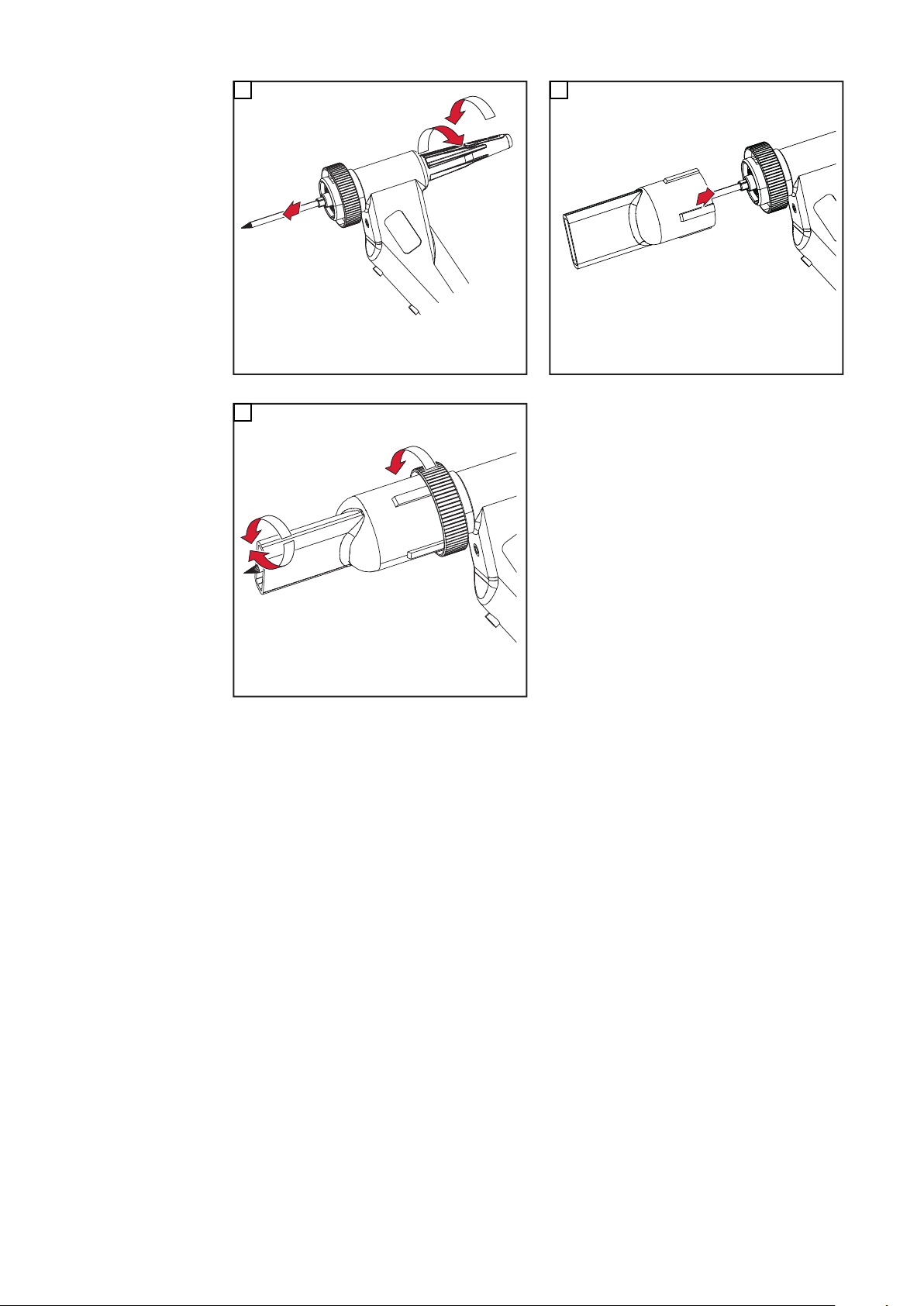
Fitting the welding torch
1
2
1
2
1
3
2
4
Safety
Fitting the TTW
4500
WARNING!
Danger due to work that has been carried out incorrectly.
This can result in severe personal injury and damage to property.
All connections must be made by trained and qualified personnel in compliance with
▶
the relevant safety regulations.
Note the safety rules in the operating instructions.
▶
WARNING!
Danger from electric current.
An electric shock can be fatal.
Before carrying out any work on the welding torch:
▶
Turn the power source mains switch to the "O" position
▶
Unplug the power source from the mains
▶
Put up an easy-to-understand warning sign to stop anybody inadvertently switching
▶
it back on again
1
2
3 4
6

Fitting the TTW
2
3
1
㪉
2
1
1
2
1
2
3
4
5
5
1
*
2
*
5500
1
3 4
2
EN
Fitting the narrow-gap gas
nozzle (option)
You will also need the following items to fit the narrow-gap gas nozzle:
- Insulation ring D 35.5 mm - 42,0100,0010
- Gas shield M18 x 1.5 mm - 42,0001,6781
- Narrow-gap gas nozzle - 42,0300,3210
1
2
* Screw on as far as it will go
7

2
1
3
~ 15 mm
3
1
**
1
2
5
4
** Push on as far as it will go
8

Troubleshooting
EN
Safety
Troubleshooting
WARNING!
Danger from electric current.
An electric shock can be fatal.
Before carrying out any work on the welding torch:
▶
Turn the power source mains switch to the "O" position
▶
Unplug the power source from the mains
▶
Put up an easy-to-understand warning sign to stop anybody inadvertently switching
▶
it back on again
Arc not igniting
Cause:
Remedy:
Cause:
Remedy:
Insufficient shielding gas cover
Cause:
Remedy:
Tungsten electrode dirty
Clean tungsten electrode
Tungsten electrode positioned incorrectly
Position tungsten electrode correctly
No gas lens in welding torch
Fit gas lens
HF is conducted to robot
Cause:
Remedy:
HF does not ignite on workpiece
Cause:
Remedy:
Electrically-conductive robot flange fitted
Fit plastic robot flange
No pilot arc
Fit pilot arc and connect pilot arc adapter
9

Care, maintenance and disposal
Safety
Danger from electric current.
An electric shock can be fatal.
▶
▶
▶
▶
General Regular preventive maintenance of the welding torch is essential for problem-free opera-
tion. The welding torch is subjected to high temperatures. It therefore requires more frequent maintenance than other components in the welding system.
At every start-up - Check welding torch, hosepack and power connections for signs of damage
- Check gas and water connections for leaks
- Check that the cooling unit is working properly, monitor the water return level in the
- Check that the wearing parts are in perfect condition, clean wearing parts before fit-
WARNING!
Before carrying out any work on the welding torch:
Turn the power source mains switch to the "O" position
Unplug the power source from the mains
Put up an easy-to-understand warning sign to stop anybody inadvertently switching
it back on again
coolant container, vent the cooling unit if necessary
ting them
Monthly - If applicable, check the filter in the cooling circuit for contamination
- Check that coolant is pure; if there are any impurities, replace the coolant and rinse
the welding torch thoroughly several times by letting coolant flow into it and back out
again
- Dismantle the welding torch and check for deposits/contamination
Disposal Dispose of in accordance with the applicable national and local regulations.
10

Technical data
EN
TTW 4500, TTW
5500
TTW 4500 TTW 5500
Voltage measurement (V-Peak) 141 V 141 V
Shielding gas Argon EN 439
Cooling system Liquid cooling
Coolant Original Fronius coolant
Cooling power 800 W *) 1000 W *)
Max. coolant pressure 5.5 bar
79.74 psi.
Min. coolant pressure 3.0 bar
43.5 psi.
Minimum coolant flow rate 1.0 l/min 1.0 l/min
DC welding current at 10
min / 40° C (104° F)
AC welding current at 10
min / 40° C (104° F)
*) Lowest cooling power according to standard IEC 60974-2
The product conforms to the requirements of standard IEC 60974-7
100% duty cycle (D.C.)
60% D.C.
100% D.C.
60% D.C.
350 A
450 A
250 A
320 A
5.5 bar
79.74 psi.
3.0 bar
43.5 psi.
430 A
550 A
300 A
400 A
11

12

Spis treści
Informacje ogólne 14
Koncepcja urządzenia 14
Obszary zastosowań 14
Zakres dostawy 14
Opcje TTW 4500 PAP 15
Opcje TTW 5500 PAP 15
Montaż palnika spawalniczego 16
Bezpieczeństwo 16
Montaż TTW 4500 16
Montaż TTW 5500 17
Montaż opcjonalnej wąskoszczelinowej dyszy gazowej 17
Lokalizacja i usuwanie usterek 19
Bezpieczeństwo 19
Lokalizacja i usuwanie usterek 19
Czyszczenie, konserwacja i utylizacja 20
Bezpieczeństwo 20
Informacje ogólne 20
Podczas każdego uruchamiania 20
Co miesiąc 20
Utylizacja 20
Dane techniczne 21
TTW 4500, TTW 5500 21
PL
13

Informacje ogólne
(1) (2) (3) (4) (5) (6) (7)
(8)
Koncepcja
urządzenia
Obszary
zastosowań
Chłodzone wodą palniki spawalnicze TIG
do aplikacji zrobotyzowanych TTW 4500
i TTW 5500 służą do spawania TIG.
Palniki spawalnicze są seryjnie
wyposażone w przyłącze Fronius F++.
W celu umożliwienia eksploatacji z typowymi, dostępnymi na rynku źródłami prądu
spawalniczego TIG, do dyspozycji są
odpowiednie adaptery. Każdy palnik
spawalniczy może być wyposażony
w przesunięty KD i dyszę osłony gazowej
wleczonej. Wiązkę uchwytu można
stosować także do określonych plazmowych palników spawalniczych.
Koncepcja urządzenia TTW 4500 / 5500 PAP
Palniki spawalnicze do aplikacji zrobotyzowanych są wykorzystywane, przykładowo,
w następujących zastosowaniach:
- podczas konstruowania rurociągów i agregatów;
- podczas budowy zbiorników;
- w przypadku konieczności spełnienia najwyższych wymogów jakościowych;
- w przypadku tworzyw specjalnych (np. tytan, stopy na bazie niklu);
- przemysł samochodowy.
Zakres dostawy
Zakres dostawy TTW 4500 PAP
(1) Ceramiczna dysza gazu ochronnego
(2) Soczewka gazowa
(3) Korpus palnika TTW
(4) Tuleja mocująca 3,2 mm
(5) Elektroda wolframowa 3,2 mm
(6) Średnia nasadka palnika
14

(7) Wiązka uchwytu ze zintegrowanym przewodem podającym drut
(1) (3) (5) (6) (7) (8) (9)
(2)
(4)
(8) Sprawdzian nastawczy
Zakres dostawy TTW 5500 PAP
(1) Ceramiczna dysza gazu ochronnego
(2) Soczewka gazowa
(3) Pierścień płaszcza gazowego
(4) Pierścień izolacyjny
(5) Korpus palnika TTW
(6) Elektroda wolframowa 4,8 mm
(7) Tuleja mocująca 4,8 mm
(8) Krótka nasadka palnika (TTW 5500)
(9) Wiązka uchwytu ze zintegrowanym przewodem podającym drut
PL
Opcje TTW 4500
PAP
Opcje TTW 5500
PAP
- Doprowadzanie zimnego drutu (system Push): Robacta Plasma / TIG KD
- Tuleja mocująca (patrz lista części zamiennych)
- Dysza gazowa M 18 x 1,5
- Adapter do złącza centralnego Fronius Z
- Dysza osłony gazowej wleczonej 50 / 100 mm
- Uchwyt obejmy mocującej
- Nasadki palnika
- Doprowadzanie zimnego drutu (system Push): Robacta KD Plasma / TIG PAP
- Tuleja mocująca 3,2 / 4 / 6,4 mm
- Dysza osłony gazowej wleczonej 50 / 100 mm
- Dysza gazowa 3/4
- Uchwyt obejmy mocującej
- Nasadki palnika
- Adapter do złącza centralnego Fronius Z
15

Montaż palnika spawalniczego
1
2
1
2
1
3
2
4
Bezpieczeństwo
Montaż TTW 4500
NIEBEZPIECZEŃSTWO!
Niebezpieczeństwo wywołane błędnym wykonaniem prac.
Skutkiem mogą być poważne uszczerbki na zdrowiu i straty materialne.
Podłączanie mogą wykonywać tylko wykwalifikowani pracownicy przy zachowaniu
▶
obowiązujących przepisów bezpieczeństwa!
Należy przestrzegać przepisów bezpieczeństwa zawartych w instrukcji obsługi.
▶
NIEBEZPIECZEŃSTWO!
Niebezpieczeństwo stwarzane przez prąd elektryczny.
Porażenie prądem elektrycznym może spowodować śmierć.
Przed wykonaniem prac przy palniku spawalniczym:
▶
Ustawić wyłącznik sieciowy źródła prądu spawania w pozycji – O –.
▶
Odłączyć źródło prądu spawania od sieci.
▶
Umieścić wyraźną tabliczkę ostrzegającą przed ponownym włączeniem.
▶
1
2
3 4
16

Montaż TTW 5500
2
3
1
㪉
2
1
1
2
1
2
3
4
5
5
1
*
2
*
1
3 4
2
PL
Montaż opcjonalnej
wąskoszczelinow
ej dyszy gazowej
Do montażu wąskoszczelinowej dyszy gazowej są dodatkowo wymagane następujące
artykuły:
- Pierścień izolacyjny D 35,5 mm — 42,0100,0010
- Pierścień płaszcza gazowego M18 x 1,5 mm — 42,0001,6781
- Wąskoszczelinowa dysza gazowa — 42,0300,3210
1
2
* Nakręcić do oporu
17

2
1
3
~ 15 mm
3
1
**
1
2
5
4
** Zamontować do oporu
18

Lokalizacja i usuwanie usterek
Bezpieczeństwo
Lokalizacja i
usuwanie usterek
NIEBEZPIECZEŃSTWO!
Niebezpieczeństwo stwarzane przez prąd elektryczny.
Porażenie prądem elektrycznym może spowodować śmierć.
Przed wykonaniem prac przy palniku spawalniczym:
▶
Ustawić wyłącznik sieciowy źródła prądu spawania w pozycji – O –.
▶
Odłączyć źródło prądu spawania od sieci.
▶
Umieścić wyraźną tabliczkę ostrzegającą przed ponownym włączeniem.
▶
Łuk spawalniczy nie zajarza się
Przyczyna:
Usuwanie:
Przyczyna:
Usuwanie:
Niewystarczająca osłona gazu ochronnego
Przyczyna:
Usuwanie:
Zabrudzenie elektrody wolframowej
Oczyścić elektrodę wolframową
Nieprawidłowe ustawienie pozycji elektrody wolframowej
Nadać elektrodzie wolframowej właściwą pozycję
Brak soczewki gazowej w palniku spawalniczym
Zamontować soczewkę gazową
PL
Iskra zapłonowa jest odprowadzana do robota
Przyczyna:
Usuwanie:
Iskra zapłonowa nie zapala się na elemencie spawanym
Przyczyna:
Usuwanie:
Zamontowany kołnierz robota przewodzący prąd elektryczny
Zamontować kołnierz robota z tworzywa sztucznego
Brak pomocniczego łuku spawalniczego
Zamontować pomocniczy łuk spawalniczy i podłączyć adapter pomoc-
niczego łuku spawalniczego
19

Czyszczenie, konserwacja i utylizacja
Bezpieczeństwo
Informacje
ogólne
Podczas każdego
uruchamiania
NIEBEZPIECZEŃSTWO!
Niebezpieczeństwo stwarzane przez prąd elektryczny.
Porażenie prądem elektrycznym może spowodować śmierć.
Przed wykonaniem prac przy palniku spawalniczym:
▶
Ustawić wyłącznik sieciowy źródła prądu spawania w pozycji – O –.
▶
Odłączyć źródło prądu spawania od sieci.
▶
Umieścić wyraźną tabliczkę ostrzegającą przed ponownym włączeniem.
▶
Regularna i profilaktyczna konserwacja palnika spawalniczego to istotny czynnik,
zapewniający bezawaryjną eksploatację. Palnik spawalniczy jest wystawiony na
działanie bardzo wysokich temperatur. Z tego powodu wymaga on częstszej konserwacji
niż pozostałe podzespoły systemu spawania.
- Sprawdzić palnik spawalniczy, wiązkę uchwytu i przyłącza prądu pod kątem
uszkodzeń.
- Sprawdzić szczelność przyłączy wody i gazu.
- Skontrolować chłodnicę pod kątem prawidłowego działania, monitorować ilość
powracającej wody w zbiorniku płynu chłodzącego, ewentualnie odpowietrzyć
chłodnicę.
- Skontrolować elementy ulegające zużyciu pod kątem ich niebudzącego zastrzeżeń
stanu; przed montażem elementów ulegających zużyciu należy je oczyścić.
Co miesiąc - Jeśli jest obecny: skontrolować filtr w układzie chłodzenia pod kątem zabrudzenia.
- Skontrolować płyn chłodzący pod kątem czystości; w przypadku stwierdzenia
zanieczyszczenia należy wymienić płyn chłodzący przez zasilanie płynu
chłodzącego, a powrót płynu chłodzącego należy kilkakrotnie przepłukać.
- Rozmontować palnik spawalniczy na części i skontrolować go pod kątem osadów/
zanieczyszczeń.
Utylizacja Utylizację przeprowadzać zgodnie z obowiązującymi krajowymi przepisami w tym
zakresie.
20

Dane techniczne
TTW 4500, TTW
5500
TTW 4500 TTW 5500
Pomiar napięcia (V-Peak) 141 V 141 V
Gaz ochronny Argon EN 439
Układ chłodzenia Chłodzenie cieczą
Płyn chłodzący Oryginalny płyn chłodzący
Fronius
Wydajność chłodzenia 800 W *) 1000 W *)
Ciśnienie płynu
chłodzącego maks.
Ciśnienie płynu
chłodzącego min.
Minimalny przepływ płynu chłodzącego 1,0 l/min 1,0 l/min
Prąd spawania (prąd
stały) przy 10 min / 40°C
(104°F)
Prąd spawania (prąd
przemienny) przy 10 min /
40°C (104°F)
5,5 bar
79,74 psi.
3,0 bar
43,5 psi.
Czas włączenia (ED)
100%
60% ED
100% ED
60% ED
350 A
450 A
250 A
320 A
5,5 bar
79,74 psi.
3,0 bar
43,5 psi.
430 A
550 A
300 A
400 A
PL
*) Najniższa wydajność chłodzenia wg normy IEC 60974-2
Produkt spełnia wymogi normy IEC 60974-7
21

22

目录
概述 24
设备设计方案 24
应用领域 24
供货范围 24
TTW 4500 PAP 选件 25
TTW 5500 PAP 选件 25
安装焊枪 26
安全须知 26
安装 TTW 4500 26
安装 TTW 5500 27
安装窄间隙气体喷嘴(可选) 27
错误诊断和错误排除 29
安全须知 29
错误诊断和错误排除 29
维护、保养和废料处理 30
安全须知 30
概述 30
每次调试时 30
每个月 30
废料处理 30
技术数据 31
TTW 4500,TTW 5500 31
ZH
23

概述
(1) (2) (3) (4) (5) (6) (7)
(8)
设备设计方案
TTW 4500 / 5500 PAP
应用领域 机器人焊枪适用于以下领域,例如:
- 管道和器械制造领域
- 容器制造领域
- 对质量有最高要求时
- 使用特殊材料时(例如:钛、镍基合金)
- 汽车和配件工业
设备设计方案
水冷型 TIG 机器人焊枪 TTW 4500 和 TTW
5500 用于 TIG 焊。
该系列焊枪均配有一个 Fronius F++ 接口。
提供各式适配器,能够在市面上常用的 TIG
设备上运行。每把焊枪均可配备已推入的
KD 或气体剥离喷嘴。综合管线也可用于特
定的等离子焊枪。
供货范围
TTW 4500 PAP
(1) 陶瓷保护气体喷嘴
(2) 气体透镜
(3) TTW 直颈
(4) 夹紧套管 3.2 mm
(5) 钨极 3.2 mm
(6) 中等焊枪盖
(7) 集成有送丝管的综合管线
(8) 定位规
供货范围
24

(1) (3) (5) (6) (7) (8) (9)
(2)
(4)
ZH
TTW 5500 PAP
供货范围
(1) 陶瓷保护气体喷嘴
(2) 气体透镜
(3) 气套环
(4) 绝缘环
(5) TTW 直颈
(6) 钨极 4.8 mm
(7) 夹紧套管 4.8 mm
(8) 短焊枪盖 (TTW 5500)
(9) 集成有送丝管的综合管线
TTW 4500 PAP 选件- 冷送丝系统(推丝系统):Robacta 等离子/TIG KD
- 夹紧套管(参见备件清单)
- 气体喷嘴 M 18 x 1.5
- 用于 Fronius Z 形中央接口的适配器
- 气体剥离喷嘴 50 / 100 mm
- 保持圈支座
- 焊枪盖
TTW 5500 PAP 选件- 冷送丝系统(推丝系统):Robacta KD 等离子 / TIG PAP
- 夹紧套管 3.2 / 4 / 6.4 mm
- 气体剥离喷嘴 50 / 100 mm
- 气体喷嘴 3/4
- 保持圈支座
- 焊枪盖
- 用于 Fronius Z 形中央接口的适配器
25

安装焊枪
1
2
1
2
1
3
2
4
安全须知
安装 TTW 4500
危险!
工作不当时存在危险。
此时可能导致严重的人身伤害和财产损失。
连接工作只允许由接受过培训的专业人员在遵守现行安全规定的情况下进行
▶
请遵守本操作说明书中的安全规程。
▶
危险!
电击可能是致命的。
电击可能致命。
在对焊枪进行作业之前:
▶
将焊接电源总开关拨到 - O - 位置
▶
将焊接电源与电网断开
▶
安装清晰可读的警示牌,防止重新接通
▶
1
2
3 4
26

安装 TTW 5500
2
3
1
㪉
2
1
1
2
1
2
3
4
5
5
1
*
2
*
1
3 4
2
ZH
安装窄间隙气体喷
嘴(可选)
要安装窄间隙气体喷嘴,您还需要:
- 绝缘环 D 35.5 mm - 42,0100,0010
- 气体保护 M18 x 1.5 mm - 42,0001,6781
- 窄间隙气体喷嘴 - 42,0300,3210
1
2
*
拧紧至无法继续拧转为止
27
2
1
3
~ 15 mm
3
1
**
1
2
5
4
**
推至无法继续推动为止
28

错误诊断和错误排除
安全须知
错误诊断和错误排
除
危险!
电击可能是致命的。
电击可能致命。
在对焊枪进行作业之前:
▶
将焊接电源总开关拨到 - O - 位置
▶
将焊接电源与电网断开
▶
安装清晰可读的警示牌,防止重新接通
▶
电弧未引燃
原因:
措施:
原因:
措施:
保护气体遮蔽不足
原因:
措施:
钨极脏污
清洁钨极
钨极定位错误
正确定位钨极
焊枪中没有气体透镜
安装气体透镜
ZH
高频被引向机器人
原因:
措施:
高频电弧没有在工件上引燃
原因:
措施:
安装了导电的机器人法兰
安装塑料机器人法兰
缺少辅助引弧装置
安装辅助引弧装置并连接辅助引弧适配器
29

维护、保养和废料处理
安全须知
电击可能是致命的。
电击可能致命。
▶
▶
▶
▶
概述 定期地进行预防性维护对焊枪的无故障运行至关重要。焊枪暴露在高温下。因此与焊接设
备其他组件相比,焊枪需要更加频繁的维护。
每次调试时 - 检查焊枪、综合管线和电流接口是否损坏
- 检查气体接口和供水接口的密封性
- 检查冷却设备的功能是否正常,检查冷却液容器内的回水流量,必要时排空冷却器
- 检查磨损件是否正常工作,在安装之前清洁磨损件
危险!
在对焊枪进行作业之前:
将焊接电源总开关拨到 - O - 位置
将焊接电源与电网断开
安装清晰可读的警示牌,防止重新接通
每个月 - 如果在冷却回路中有过滤器,检查是否脏污
- 检查冷却液的纯度;冷却液严重脏污时应更换,同时通过冷却液入口和冷却液出口多
次冲洗焊枪
- 拆卸焊枪,检查是否有沉积物/脏污
废料处理 按照国家和地区的现行法规对废料进行处理。
30

技术数据
TTW 4500,TTW
5500
TTW 4500 TTW 5500
额定电压(峰值,单位为 V) 141 V 141 V
保护气体 氩气 EN 439
冷却系统 液体冷却
冷却剂 Fronius 原装冷却剂
制冷效率 800 W *) 1000 W *)
冷却剂最大压力 5.5 bar
79.74 psi.
冷却剂最小压力 3.0 bar
43.5 psi.
冷却剂最小流量 1.0 l/min 1.0 l/min
10 min/40° C (104° F) 时
的 DC 焊接电流
10 min/40° C (104° F) 时
的 AC 焊接电流
*) 最低制冷效率符合 IEC 60974-2 标准
该产品符合 IEC 60974-7 标准的要求
100% 工作周期 (ED)
60% ED
100% (ED)
60% ED
350 A
450 A
250 A
320 A
5.5 bar
79.74 psi.
3.0 bar
43.5 psi.
430 A
550 A
300 A
400 A
ZH
31

FRONIUS INTERNATIONAL GMBH
Froniusstraße 1
A-4643 Pettenbach
AUSTRIA
contact@fronius.com
www.fronius.com
Under www.fronius.com/contact you will find the addresses
of all Fronius Sales & Service Partners and locations
 Loading...