

Page 1
TransTig 1600
TransTig 1700
Operating Instructions
GB
Spare Parts List
TIG power source
42,0426,0023,EN 003-08112013
42,0426,0023,EN 012006
Page 2

Page 3

Dear Reader
Introduction
Thank you for choosing Fronius - and congratulations on your new, technically highgrade Fronius product! This instruction manual will help you get to know your new
machine. Read the manual carefully and you will soon be familiar with all the many
great features of your new Fronius product. This really is the best way to get the most
out of all the advantages that your machine has to offer.
Please also take special note of the safety rules - and observe them! In this way, you
will help to ensure more safety at your product location. And of course, if you treat your
product carefully, this definitely helps to prolong its enduring quality and reliability - things
which are both essential prerequisites for getting outstanding results.
ud_fr_st_et_00493 012004
Page 4

Page 5
Safety rules
DANGER!
WARNING!
CAUTION!
NOTE!
Important!
“DANGER!” indicates an imminently hazardous situation which, if not
avoided, will result in death or serious injury. This signal word is to be
limited to the most extreme situations. This signal word is not used for
property damage hazards unless personal injury risk appropriate to this
level is also involved.
“WARNING!” indicates a potentially hazardous situation which, if not
avoided, could result in death or serious injury. This signal word is not used
for property damage hazards unless personal injury risk appropriate to this
level is also involved.
“CAUTION!” indicates a potentially hazardous situation which, if not
avoided, may result in minor or moderate injury. It may also be used to
alert against unsafe practices that may cause property damage.
“NOTE!” indicates a situation which implies a risk of impaired welding result
and damage to the equipment.
“Important!” indicates practical hints and other useful special-information. It is no
signal word for a harmful or dangerous situation.
EN
General remarks
Whenever you see any of the symbols shown above, you must pay even closer
attention to the contents of the manual!
This equipment has been made in accordance with the state of the art and
all recognised safety rules. Nevertheless, incorrect operation or misuse may
still lead to danger for
- the life and well-being of the operator or of third parties,
- the equipment and other tangible assets belonging to the owner/
operator,
- efficient working with the equipment.
All persons involved in any way with starting up, operating, servicing and
maintaining the equipment must
- be suitably qualified
- know about welding and
- read and follow exactly the instructions given in this manual.
The instruction manual must be kept at the machine location at all times. In
addition to the instruction manual, copies of both the generally applicable
and the local accident prevention and environmental protection rules must
be kept on hand, and of course observed in practice.
All the safety instructions and danger warnings on the machine itself:
- must be kept in a legible condition
- must not be damaged, must not be removed
- must not be covered, pasted or painted over
For information about where the safety instructions and danger warnings
are located on the machine, please see the section of your machine’s
instruction manual headed “General remarks”.
I
ud_fr_st_sv_00467 022013
Page 6

General remarks
(continued)
Any malfunctions which might impair machine safety must be eliminated
immediately - meaning before the equipment is next switched on.
It’s your safety that’s at stake!
Utilisation for
intended purpose
only
The machine may only be used for jobs as defined by the “Intended purpose”.
The machine may ONLY be used for the welding processes stated on the
rating plate.
Utilisation for any other purpose, or in any other manner, shall be deemed to
be "not in accordance with the intended purpose". The manufacturer shall
not be liable for any damage resulting from such improper use.
Utilisation in accordance with the “intended purpose” also comprises
- complete reading and following of all the instructions given in this manual
- complete reading and following of all the safety instructions and danger
warnings
- performing all stipulated inspection and servicing work.
The appliance must never be used for the following:
- Thawing pipes
- Charging batteries/accumulators
- Starting engines
The machine is designed to be used in industrial and workshop
environments. The manufacturer shall not be liable for any damage resulting
from use of the machine in residential premises.
ikewise the manufacturer will accept no liability for defective or faulty work
results.
Ambient
conditions
Obligations of
owner/operator
Operation or storage of the power source outside the stipulated range is
deemed to be “not in accordance with the intended use”. The manufacturer
shall not be liable for any damage resulting herefrom.
Temperature range of ambient air:
- when operating: - 10 °C to + 40 °C (14 °F to 104 °F)
- when being transported or stored: - 20 °C to + 55 °C (-4 °F to 131 °F)
Relative atmospheric humidity:
- up to 50 % at 40 °C (104 °F)
- up to 90 % at 20 °C (68 °F)
Ambient air: Free of dust, acids, corrosive gases or substances etc.
Elevation above sea level: Up to 2000 m (6500 ft)
The owner/operator undertakes to ensure that the only persons allowed to
work with the machine are persons who
- are familiar with the basic regulations on workplace safety and accident
prevention and who have been instructed in how to operate the machine
- have read and understood this operating manual particulary the sections
on “Safety rules”, and have confirmed as much with their signatures
- be trained in such a way that meets with the requirements of the work
results
ud_fr_st_sv_00467 022013
Regular checks must be performed to ensure that personnel are still working
in a safety-conscious manner.
II
Page 7
Obligations of
personnel
Before starting work, all persons to be entrusted with carrying out work with
(or on) the machine shall undertake
- to observe the basic regulations on workplace safety and accident
prevention
- to read this operating manual particulary the sections on “Safety rules”
and to sign to confirm that they have understood these and will comply
with them.
EN
Before leaving the workplace, personnel must ensure that there is no risk of
injury or damage being caused during their absence.
Mains connection
Protection for
yourself and
other persons
High-performance devices can affect the quality of the mains power due to
their current-input.
This may affect a number of types of device in terms of:
- connection restrictions
- criteria with regard to maximum permissible mains impedance
- criteria with regard to minimum short-circuit power requirement
*)
at the interface with the public mains network
*)
*)
see Technical Data
In this case, the plant operator or the person using the device should check
whether or not the device is allowed to be connected, where appropriate
through discussion with the power supply company.
NOTE! Ensure that the mains connection is earthed properly.
When welding, you are exposed to many different hazards such as:
- flying sparks and hot metal particles
- arc radiation which could damage your eyes and skin
- harmful electromagnetic fields which may put the lives of cardiac pacemaker users at risk
- electrical hazards from mains and welding current
- increased exposure to noise
- noxious welding fumes and gases.
Anybody working on the workpiece during welding must wear suitable
protective clothing with the following characteristics:
- flame-retardant
- isolating and dry
- must cover whole body, be undamaged and in good condition
- protective helmet
- trousers with no turn-ups
III
ud_fr_st_sv_00467 022013
Page 8
Protection for
yourself and
other persons
(continued)
“Protective clothing” also includes:
- protecting your eyes and face from UV rays, heat and flying sparks with
an appropriate safety shield containing appropriate regulation filter glass
- wearing a pair of appropriate regulation goggles (with sideguards)
behind the safety shield
- wearing stout footwear that will also insulate even in wet conditions
- protecting your hands by wearing appropriate gloves (electrically insulating, heat-proof)
- To lessen your exposure to noise and to protect your hearing against
injury, wear ear-protectors!
Keep other people - especially children - well away from the equipment and
the welding operation while this is in progress. If there are still any other
persons nearby during welding, you must
- draw their attention to all the dangers (risk of being dazzled by the arc or
injured by flying sparks, harmful welding fumes, high noise immission
levels, possible hazards from mains or welding current ...)
- provide them with suitable protective equipment and/or
- erect suitable protective partitions or curtains.
Information on
noise emission
values
Hazards from
noxious gases
and vapours
The device generates a maximum sound power level of <80 dB(A) (ref. 1pW)
when idling and in the cooling phase following operation at the maximum
permissible operating point under maximum rated load conditions according
to EN 60974-1.
It is not possible to provide a workplace-related emission value during welding (or cutting) as this is influenced by both the process and the environment. All manner of different welding parameters come into play, including the
welding process (MIG/MAG, TIG welding), the type of power selected (DC or
AC), the power range, the type of weld metal, the resonance characteristics
of the workpiece, the workplace environment, etc.
The fumes given off during welding contain gases and vapors that are
harmful to health.
Welding fumes contain substances which may cause birth defects and
cancers.
Keep your head away from discharges of welding fumes and gases.
Do not inhale any fumes or noxious gases that are given off.
Extract all fumes and gases away from the workplace, using suitable
means.
ud_fr_st_sv_00467 022013
Ensure a sufficient supply of fresh air.
Where insufficient ventilation is available, use a respirator mask with an
independent air supply.
If you are not sure whether your fume-extraction system is sufficiently
powerful, compare the measured pollutant emission values with the
permitted threshold limit values.
Close the shielding gas cylinder valve or central gas supply if no welding is
taking place.
IV
Page 9
Hazards from
noxious gases
and vapours
(continued)
The harmfulness of the welding fumes will depend on e.g. the following
components:
- the metals used in and for the workpiece
- the electrodes
- coatings
- cleaning and degreasing agents and the like
Hazards from
flying sparks
For this reason, pay attention to the relevant Materials Safety Data Sheets
and the information given by the manufacturer regarding the components
listed above.
Keep all flammable vapors (e.g. from solvents) well away from the arc
radiation.
Flying sparks can cause fires and explosions!
Never perform welding anywhere near combustible materials.
Combustible materials must be at least 11 meters (36 ft. 1.07 in.) away from
the arc, or else must be covered over with approved coverings.
Have a suitable, approved fire extinguisher at the ready.
Sparks and hot metal particles may also get into surrounding areas through
small cracks and openings. Take suitable measures here to ensure that
there is no risk of injury or fire.
Do not perform welding in locations that are at risk from fire and/or
explosion, or in enclosed tanks, barrels or pipes, unless these latter have
been prepared for welding in accordance with the relevant national and
international standards.
EN
Hazards from
mains and welding current
Welding must NEVER be performed on containers that have had gases,
fuels, mineral oils etc. stored in them. Even small traces of these
substances left in the containers are a major explosion hazard.
An electric shock is potentially life-threatening, and can be fatal.
Do not touch any live parts, either inside or outside the machine.
In MIG/MAG and TIG welding, the welding wire, the wire spool, the drive
rollers and all metal parts having contact with the welding wire are also live.
Always place the wirefeeder on an adequately insulated floor or base, or
else use a suitable insulating wirefeeder holder.
Ensure sufficient protection for yourself and for other people by means of a
dry base or cover that provides adequate insulation against the ground/
frame potential. The base or cover must completely cover the entire area
between your body and the ground/frame potential.
All cables and other leads must be firmly attached, undamaged, properly
insulated and adequately dimensioned. Immediately replace any loose
connections, scorched, damaged or underdimensioned cables or other
leads.
V
ud_fr_st_sv_00467 022013
Page 10

Hazards from
mains and welding current
(continued)
Do not loop any cables or other leads around your body or any part of your
body.
Never immerse the welding electrode (rod electrode, tungsten electrode,
welding wire, ...) in liquid in order to cool it, and never touch it when the
power source is ON.
Twice the open-circuit voltage of one single welding machine may occur
between the welding electrodes of two welding machines. Touching the
potentials of both electrodes simultaneously may be fatal.
Have the mains and the machine supply leads checked regularly by a
qualified electrician to ensure that the PE (protective earth) conductor is
functioning correctly.
Only run the machine on a mains network with a PE conductor, and plugged
into a power outlet socket with a protective-conductor contact.
If the machine is run on a mains network without a PE conductor and
plugged into a power outlet socket without a protective-conductor contact,
this counts as gross negligence and the manufacturer shall not be liable for
any resulting damage.
Wherever necessary, use suitable measures to ensure that the workpiece is
sufficiently grounded (earthed).
Stray welding
currents
Switch off any appliances that are not in use.
Wear a safety harness if working at height.
Before doing any work on the machine, switch it off and unplug it from the
mains.
Put up a clearly legible and easy-to-understand warning sign to stop
anybody inadvertently plugging the machine back into the mains and
switching it back on again.
After opening up the machine:
- discharge any components that may be storing an electrical charge
- ensure that all machine components are electrically dead.
If work needs to be performed on any live parts, there must be a second
person on hand to immediately switch off the machine at the main switch in
an emergency.
If the following instructions are ignored, stray welding currents may occur.
These can cause:
- fires
- overheating of components that are connected to the workpiece
- destruction of PE conductors
- damage to the machine and other electrical equipment
ud_fr_st_sv_00467 022013
Ensure that the workpiece clamp is tightly connected to the workpiece.
Attach the workpiece clamp as close as possible to the area to be welded.
On electrically conductive floors, the machine must be set up in such a way
that it is sufficiently insulated from the floor.
VI
Page 11
Stray welding
currents
(continued)
When using current supply distributors, twin head wire feeder fixtures etc.,
please note the following: The electrode on the unused welding torch/
welding tongs is also current carrying. Please ensure that there is sufficient
insulating storage for the unused welding torch/tongs.
In the case of automated MIG/MAG applications, ensure that only insulated
filler wire is routed from the welding wire drum, large wirefeeder spool or
wirespool to the wirefeeder.
EN
EMC device
classifications
Devices with emission class A:
- are only designed for use in an industrial setting
- can cause conducted and emitted interference in other areas.
Devices with emission class B:
- satisfy the emissions criteria for residential and industrial areas. This
also applies to residential areas in which power is supplied from the
public low-voltage grid.
EMC device classification as per the rating plate or technical specifications
EMC measures In certain cases, even though a device complies with the standard limit values
for emissions, it may affect the application area for which it was designed (e.g.
when there is sensitive equipment at the same location, or if the site where
the device is installed is close to either radio or television receivers).
If this is the case, then the operator is obliged to take appropriate action to
rectify the situation.
Examine and evaluate any possible electromagnetic problems that may
occur on equipment in the vicinity, and the degree of immunity of this
equipment, in accordance with national and international regulations:
- safety features
- mains, signal and data-transmission leads
- IT and telecoms equipment
- measurement and calibration devices
Ancillary measures for preventing EMC problems:
a) Mains supply
- If electromagnetic interference still occurs, despite the fact that the
mains connection is in accordance with the regulations, take additional
measures (e.g. use a suitable mains filter).
b) Welding cables
- Keep these as short as possible
- Arrange them so that they run close together (to prevent EMI problems
as well)
- Lay them well away from other leads.
c) Equipotential bonding
d) Workpiece grounding (earthing)
- where necessary, run the connection to ground (earth) via suitable
capacitors.
e) Shielding, where necessary
- Shield other equipment in the vicinity
- Shield the entire welding installation.
VII
ud_fr_st_sv_00467 022013
Page 12
EMI Precautions
Electromagnetic fields may cause as yet unknown damage to health.
- Effects on the health of persons in the vicinity, e.g. users of heart pacemakers and hearing aids
- Users of heart pacemakers must take medical advice before going
anywhere near welding equipment or welding workplaces
- Keep as much space as possible between welding cables and head/
body of welder for safety reasons
- Do not carrywelding cables and hose pack over shoulder and do not
loop around body or or any part of body
Particular danger
spots
Keep your hands, hair, clothing and tools well away from all moving parts,
e.g.:
- fans
- toothed wheels, rollers, shafts
- wire-spools and welding wires
Do not put your fingers anywhere near the rotating toothed wheels of the
wirefeed drive.
Covers and sideguards may only be opened or removed for as long as is
absolutely necessary to carry out maintenance and repair work.
While the machine is in use:
- ensure that all the covers are closed and that all the sideguards are
properly mounted ...
- ... and that all covers and sideguards are kept closed.
When the welding wire emerges from the torch, there is a high risk of injury
(the wire may pierce the welder’s hand, injure his face and eyes ...).
For this reason, when feeder-inching etc., always hold the torch so that it is
pointing away from your body (machines with wirefeeder) and wear suitable
protective goggles.
Do not touch the workpiece during and after welding - risk of injury from
burning!
Slag may suddenly “jump” off workpieces as they cool. For this reason,
continue to wear the regulation protective gear, and to ensure that other
persons are suitably protected, when doing post-weld finishing on
workpieces.
Allow welding torches - and other items of equipment that are used at high
operating temperatures - to cool down before doing any work on them.
Special regulations apply to rooms at risk from fire and/or explosion.
Observe all relevant national and international regulations.
Power sources for use in spaces with increased electrical danger (e.g.
boilers) must be identified by the (for “safety”) mark.
However, the power source should not be in such rooms.
ud_fr_st_sv_00467 022013
VIII
Page 13

Particular danger
spots
(continued)
Risk of scalding from accidental discharge of hot coolant. Before unplugging
the connectors for coolant forward flow and return flow, switch off the cooling unit.
Observe the information on the coolant safety data sheet when handling
coolant. The coolant safety data sheet may be obtained from your service
centre or downloaded from the manufacturer’s website.
When hoisting the machines by crane, only use suitable manufacturersupplied lifting devices.
- Attach the chains and/or ropes to all the hoisting points provided on the
suitable lifting device.
- The chains and/or ropes must be at an angle which is as close to the
vertical as possible.
- Remove the gas cylinder and the wirefeed unit (from MIG/MAG and TIG
units).
When hoisting the wirefeed unit by crane during welding, always use a
suitable, insulating suspension arrangement (MIG/MAG and TIG units).
If a machine is fitted with a carrying strap or carrying handle, remember that
this strap is ONLY to be used for lifting and carrying the machine by hand.
The carrying strap is NOT suitable for transporting the machine by crane,
fork-lift truck or by any other mechanical hoisting device.
EN
Factors affecting
welding results
All lifting accessories (straps, handles, chains, etc.) used in connection with
the device or its components must be tested regularly (e.g. for mechanical
damage, corrosion or changes caused by other environmental factors).
The testing interval and scope of testing must comply with applicable national standards and directives as a minimum.
Danger of colourless and odourless inert gas escaping unnoticed, when
using an adapter for the inert gas protection. Seal the adapter thread for the
inert gas connection using Teflon tape before assembly.
The following requirements with regard to shielding gas quality must be met
if the welding system is to operate in a correct and safe manner:
- Size of solid matter particles <40µm
- Pressure dew point <-20°C
- Max. oil content <25mg/m³
Filters must be used if necessary.
NOTE! There is an increased risk of soiling if ring mains are being
used
IX
ud_fr_st_sv_00467 022013
Page 14
Danger from
shielding-gas
cylinders
Shielding-gas cylinders contain pressurized gas and may explode if they are
damaged. As shielding-gas cylinders are an integral part of the overall
welding outfit, they also have to be treated with great care.
Protect shielding-gas cylinders containing compressed gas from excessive
heat, mechanical impact, slag, naked flames, sparks and arcs.
Mount the shielding-gas cylinders in the vertical and fasten them in such a
way that they cannot fall over (i.e. as shown in the instruction manual).
Keep shielding-gas cylinders well away from welding circuits (and, indeed,
from any other electrical circuits).
Never hang a welding torch on a shielding-gas cylinder.
Never touch a shielding-gas cylinder with a welding electrode.
Explosion hazard - never perform welding on a pressurized shielding-gas
cylinder.
Use only shielding-gas cylinders that are suitable for the application in
question, together with matching, suitable accessories (pressure regulators,
hoses and fittings, ...). Only use shielding-gas cylinders and accessories
that are in good condition.
Safety precautions at the installation site and
when being
transported
When opening the valve of a shielding-gas cylinder, always turn your face
away from the outlet nozzle.
Close the shielding-gas cylinder valve when no welding is being carried out.
When the shielding-gas cylinder is not connected up, leave the cap in place
on the shielding-gas cylinder valve.
Observe the manufacturer’s instructions and all relevant national and
international rules applying to shielding-gas cylinders and accessories.
A machine that topples over can easily kill someone! For this reason, always
place the machine on an even, firm floor in such a way that it stands firmly.
- An angle of inclination of up to 10° is permissible.
Special regulations apply to rooms at risk from fire and/or explosion.
Observe all relevant national and international regulations.
By means of internal instructions and checks, ensure that the workplace and
the area around it are always kept clean and tidy.
ud_fr_st_sv_00467 022013
The appliance must only be installed and operated in accordance with the
protection type stated on the specifications plate.
When installing the appliance, please ensure a clearance radius of 0.5 m
(1.6ft.) , so that cool air can circulate freely.
When transporting the appliance, please ensure that the valid national and
regional guidelines and accident protection regulations are followed. This
applies in particular to guidelines in respect of dangers during transportation and carriage.
X
Page 15

Safety precautions at the installation site and
when being
transported
(continued)
Before transportation, completely drain any coolant and dismantle the
following components:
- Wire feed
- Wire wound coil
- Gas bottle
Before commissioning and after transportation, a visual check for damage
must be carried out. Any damage must be repaired by trained service
personnel before commissioning.
EN
Safety precautions in normal
operation
Only operate the machine if all of its protective features are fully functional. If
any of the protective features are not fully functional, this endangers:
- the life and well-being of the operator or other persons
- the equipment and other tangible assets belonging to the owner/operator
- efficient working with the equipment.
Any safety devices that are not fully functional must be put right before you
switch on the machine.
Never evade safety features and never put safety features out of order.
Before switching on the machine, ensure that nobody can be endangered by
your doing so.
- At least once a week, check the machine for any damage that may be
visible from the outside, and check that the safety features all function
correctly.
- Always fasten the shielding-gas cylinder firmly, and remove it altogether
before hoisting the machine by crane.
- Owing to its special properties (in terms of electrical conductivity, frostproofing, materials-compatibility, combustibility etc.), only original coolant
of the manufacturer is suitable for use in our machines.
- Only use suitable original coolant of the manufacturer.
- Do not mix original coolant of the manufacturer with other coolants.
- If any damage occurs in cases where other coolants have been used,
the manufacturer shall not be liable for any such damage, and all
warranty claims shall be null and void.
- Under certain conditions, the coolant is flammable. Only transport the
coolant in closed original containers, and keep it away from sources of
ignition.
- Used coolant must be disposed of properly in accordance with the
relevant national and international regulations. A safety data sheet is
available from your service centre and on the manufacturer’s homepage.
- Before starting welding - while the machine is still cool - check the
coolant level.
XI
ud_fr_st_sv_00467 022013
Page 16
Preventive and
corrective maintenance
With parts sourced from other suppliers, there is no certainty that these
parts will have been designed and manufactured to cope with the stressing
and safety requirements that will be made of them. Use only original spares
and wearing parts (this also applies to standard parts).
Do not make any alterations, installations or modifications to the machine
without getting permission from the manufacturer first.
Replace immediately any components that are not in perfect condition.
When ordering spare parts, please state the exact designation and the
relevant part number, as given in the spare parts list. Please also quote the
serial number of your machine.
Safety inspection
Disposal
The manufacturer recommends that a safety inspection of the device is
performed at least once every 12 months.
The manufacturer recommends that the power source be calibrated during
the same 12-month period.
A safety inspection should be carried out by a qualified electrician
- after any changes are made
- after any additional parts are installed, or after any conversions
- after repair, care and maintenance has been carried out
- at least every twelve months.
For safety inspections, follow the appropriate national and international
standards and directives.
Further details on safety inspection and calibration can be obtained from
your service centre. They will provide you on request with any documents
you may require.
Do not dispose of this device with normal domestic waste!
To comply with the European Directive 2002/96/EC on Waste Electrical and
Electronic Equipment and its implementation as national law, electrical
equipment that has reached the end of its life must be collected separately
and returned to an approved recycling facility Any device that you no longer
require must be returned to our agent, or find out about the approved
collection and recycling facilities in your area.
Ignoring this European Directive may have potentially adverse affects on the
environment and your health!
Safety markings
ud_fr_st_sv_00467 022013
Equipment with CE-markings fulfils the basic requirements of the LowVoltage and Electromagnetic Compatibility Guideline (e.g. relevant product
standards according to EN 60 974). .
Equipment marked with the CSA-Test Mark fulfils the requirements made in
the relevant standards for Canada and the USA.
XII
Page 17

Data security
The user is responsible for the data security of changes made to factory
settings. The manufacturer is not liable, if personal settings are deleted.
Copyright
Copyright to this instruction manual remains the property of the
manufacturer.
The text and illustrations are all technically correct at the time of going to
print. The right to effect modifications is reserved. The contents of the
instruction manual shall not provide the basis for any claims whatever on the
part of the purchaser. If you have any suggestions for improvement, or can
point out to us any mistakes which you may have found in the manual, we
should be most grateful for your comments.
EN
XIII
ud_fr_st_sv_00467 022013
Page 18

ud_fr_st_sv_00467 022013
XIV
Page 19

Contents
General Details ............................................................................................................................................. 2
Basic system principle.............................................................................................................................. 2
Construction ............................................................................................................................................. 2
Functional sequence ................................................................................................................................ 2
Control panel ................................................................................................................................................. 3
TT 1700 control panel .............................................................................................................................. 3
Description of functions ............................................................................................................................ 3
Connections, switches and system add-ons ................................................................................................. 6
Connections and switches on the rear of the machine ............................................................................ 6
Connection points on front of machine..................................................................................................... 6
Assembling a gas-cooled TIG torch .............................................................................................................. 7
Design with central burner connection GWZ............................................................................................ 7
Design with Fronius central welding torch connection F ..........................................................................7
Commissioning - General details .................................................................................................................. 8
Mains connection ..................................................................................................................................... 8
Setting-up instructions.............................................................................................................................. 8
TIG operating modes .................................................................................................................................... 9
General remarks ...................................................................................................................................... 9
2-step mode ............................................................................................................................................. 9
Special 2-step mode .............................................................................................................................. 10
4-step mode - without intermediate lowering...........................................................................................11
4-step mode - with intermediate lowering .............................................................................................. 12
Special 4-step mode - Variant I .............................................................................................................. 13
Special 4-step mode - Variant II / III / IV / V ........................................................................................... 14
Working with the program levels ................................................................................................................. 16
Accessing the relevant program level .................................................................................................... 16
Presettings level --- ................................................................................................................................ 16
Service-menu Level P1 .......................................................................................................................... 16
Level codelock P2 .................................................................................................................................. 17
TIG welding with high-frequency ignition (HF)............................................................................................. 18
Start up................................................................................................................................................... 18
TIG welding with contact ignition (without HF) ............................................................................................ 20
Start up................................................................................................................................................... 20
Manual electrode welding ............................................................................................................................ 21
Start up................................................................................................................................................... 21
Remote control operation ............................................................................................................................ 22
General .................................................................................................................................................. 22
TR 50mc remote control pulsing unit ..................................................................................................... 22
TR 52mc remote control pedal unit ........................................................................................................ 26
TR 51mc remote control spot-welding unit............................................................................................. 27
TPmc remote control unit ....................................................................................................................... 28
Troubleshooting........................................................................................................................................... 30
Safety ..................................................................................................................................................... 30
Displayed service codes ........................................................................................................................ 30
Troubleshooting ..................................................................................................................................... 30
Care, maintenance and disposal ................................................................................................................. 33
Technical data ............................................................................................................................................. 34
TransTig 1600 / TransTig 1700 ............................................................................................................. 34
Spare parts list
Circuit diagram
Fronius Worldwide
1
Page 20

General Details
Basic system
principle
Designed as a primary transistor-switched welding machine, the welding rectifier
TRANSTIG 1600 / 1700 (DC) represents a further deve-lopment of the transistor controlled welding machine. It is especially suitable for TIG-manual-, and MANUAL ELECTRODE WELDING in the DC area. The machine’s compact dimensions, low weight and
modest power requirements are important advantages, both in the production and repair
fields.UP/DOWN control (continuous welding-current regulation via torch trigger) is also
integrated as standard.
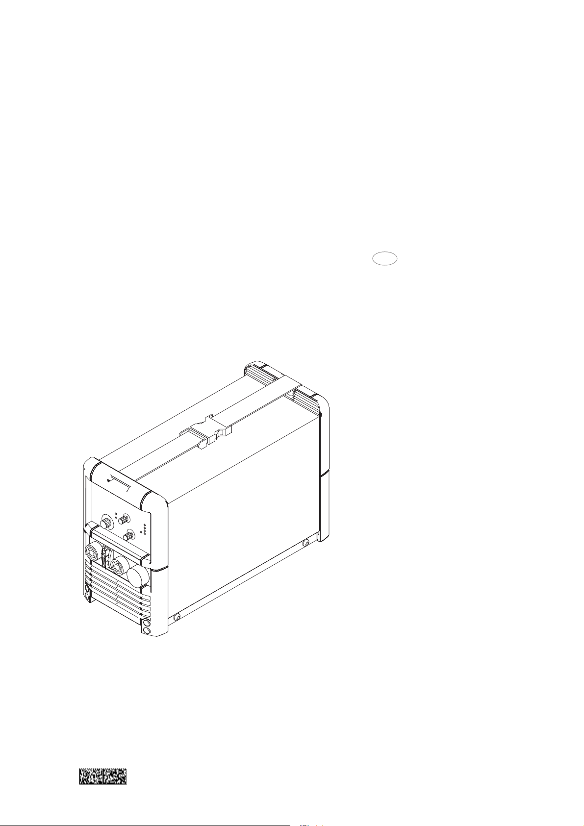
Construction Features such as its powder-coated sheet-steel housing, the way its controls are pro-
tected by a plastic frame, and its bayonet-latching current sockets all testify to the high
quality of its design. The shoulder strap makes the unit easy to move around, both within
the factory and e.g. out on building sites.
Functional sequence
The voltage from the mains power supply is rectified. A rapid transistor switching device
inverts this voltage using a frequency of 100 kHz. The welding transformer produces the
required working voltage, which is rectified and fed to the output sockets. An electronic
controller adjusts the power-source characteristic
to suit the pre-selected welding process.
Operational readiness operator is lit up
Welding current control set to required value
Start of welding process
+45°C on heat dissipator -> Cooling switches ON
+40°C aon heat dissipator -> Cooling switches OFF
+85°C on secondary heat dissipator -> Welding current switches OFF
+80°C on secondary heat dissipator -> Welding current switches ON
Fig. 1 Principle of the thermostatic cut-out system
Thermostatic
cut-out system
2
Page 21

Control panel
WARNING! Operating the equipment incorrectly can cause serious injury and
damage. Do not use the functions described here until you have read and
completely understood all of the following documents:
- these Operating Instructions
- all “Operating Instructions” for the system components, especially the
“Safety rules”
TT 1700
control panel
214 3
8
Description of
functions
11
10
9
13
15
Fig. 2 Front panel Transtig 1700
Item Function
(1) Mains ON / OFF switch (see Fig.5)
(2) Digital-Ammeter
Indicator of the main current
Command value -> desired welding current
Actual value -> actual welding current
(3) Digital-Voltmeter
Indicator of the welding voltage
(4) Function button
7
6
5
12
4
16
a) 2-step operation -> TIG welding with HF-ignition
b) 4-step operation -> TIG welding with HF-ignition
+ c) 2-step operation -> TIG welding with contact ignition
+ d) 4-step operation -> TIG welding with contact ignition
- Arc force control and hot-start devices are out of action
- When the TR 50mc, TR 51mc and TR 52mc remote-control units are used,
the system switches over to the operating mode in question automatically
- LED indicators (7) or (8) resp. (6) + (7) or (6) + (8) lights up
3
Page 22

Description of
functions
(continued)
e) Manual electrode welding
- LED indicator (5) lights up and the digital voltmeter indicates the open-circuit
voltage.
- The welding characteristics are governed by the values for ARC FORCE and
HOT-START which are fixed in the machine itself.
- It is possible to influence these parameters from outside via the TPmc remote
control unit and the inert menue at function selector switch position
(5) LED indicator for manual electrode welding
- Select via function button (4)
- LED indicator (10) lights up (for main current I
) only at welding
H
- Welding current is present in the current socket [B]
- Welding current is either adjusted with the main current re-gulator (15), or via
the dial (34) on the TPmc remote control unit
(6) LED indicator for contact ignition
- Select via function button (4)
- Lights up together with either LED (7) or LED (8)
- To ignite the arc, touch the workpiece with the tungsten electrode after
pressing the torch trigger.
- The short-circuit current flowing when contact is made bet-ween the electrode
and the workpiece corresponds to the minimum current.
Where to use contact ignition: Whenever the HF used in contact-free ignition
would cause external interference.
(7) LED indicator for 4-step mode
(8) LED indicator for 2-step mode
(9) Starting current LED indicator I
S
- lights up when the starting current IS is active
(9) Starting current LED indicator I
S
- lights up when the starting current IS is active
(10) Main current LED indicator I
H
- lights up when the main current IH is active
(11) DOWN-SLOPE or current drop time
- For continuous adjustment of the current drop speed from the main current
down to the crater-fill current I
E
Range: 0,1 to 20 seconds
- When the Down-Slope potentiometer is used, the pre-set value will be indicated for 3 seconds
e. g.: d S L 1.0
(12) Final current LED indicator I
E
- lights up when the final current IE is active
(13) LED indicator for TIG pulsed-arc welding
- As soon as the TIG pulsed-arc remote-control unit TR 50mc is connected up,
the LED (13) starts to flash (see the section headed “TIG pulsed-arc remotecontrol unit TR 50mc”)
4
Page 23

Description of
functions
(continued)
(14) LED indicator "HOLD"
- Permits subsequent checking of the welding parameters
- Lights up after actual values have been stored (end of welding)
- The mean of the welding current and voltage values measured before the end
of a welding operation is indicated by the digital displays (2) and (3)
- The function works in the operating mode for r.c. pedal unit, and pulsed-arc
welding up to 20 Hz
Ways of deleting the HOLD function:
- By actuating the torch trigger between welds
- Switch the mains master switch off and back on again
- By adjusting the welding current dial (15) during the breaks between welding
- By pressing the function button (4)
- Every time you start welding
(15) Main current dial IH = welding current
- For continuous adjustment of the welding current over the
2-140 A electrode or 2-160 A / 170A TIG range
- LED indicator (10) lights up (only at electrode operating mode)
- The digital ammeter indicates the command value for current as soon as the
machine is in open circuit, and then switches over to an indication of the
actual value.
Command value -> desired welding current
Actual value -> actual welding current
(16) CRATER-FILL CURRENT: I
E
- Only possible in 4-step operation
- Is set as a %-age of the main current
When the crater-fill current potentiometer is used, the pre-set value will be
indicated for 3 seconds
- The welding current is lowered to the crater-fill current when the torch trigger
is pressed.
- LED control light (12) indicates that this is taking place
The following parameters are laid down
- Gas pre-flow time ............................................ 0,4 sec.
- Start arc .......................................................... 29% of I
H
- Up-slope .......................................................... 1,0 sec.
- Gas post-flow time .......................................... 5-15 sec.
All parameters can be changed individually, via a program menu.
5
Page 24

Connections, switches and system add-ons
Connection
points on front of
machine
Connections and
switches on the
rear of the machine
Fig. 3 Design with central welding torch connec-
tion GWZ
[A] TIG TORCH CONNECTION
- for connecting the GAS + CURRENT supply for the welding torch
[B] (+) SOCKET with bayonet coupling
- as the earth cable connection point with TIG welding;
- as the connection either for the manual electrode cable or the earth cable
with manual electrode welding, depending on the type of electrode used.
[C] TORCH CONTROL SOCKET
- Steuerstecker des Schweißbrenners einstecken und verriegeln
[D] (-) SOCKET with bayonet coupling
- only for welding torch central connection GWZ
- as the connection either for the manual electrode cable or the earth cable with
manual electrode welding, depending on the type of electrode used.
Fig. 4 Design with central welding torch connec-
tion F
Fig. 5 Rear side of the machine
[E] GAS CONNECTION
- Screw the terminal nut of the gas hose onto the connection-fitting and tighten
it
[F] MAINS CABLE WITH STRAIN-RELIEF GRIP
[G] CONNECTING SOCKET for remote control unit
- Plug the remote control cable plug into the socket, the right way round, and
tighten the swivel nut
- The desired welding current is set on the remote control unit.
- The machine automatically recognizes the fact that the remote control unit
has been plugged in
- The short-circuit-proof supply voltage to the remote control units protects the
electronics in the event of any damage to the remote control cable.
6
Page 25

Assembling a gas-cooled TIG torch
Design with
central burner
connection GWZ
- Pull back the rubber sleeve from the rear of the torch
- Screw the hexagon nut (width across = 21) of the gas+current connection onto the
torch connector point on the machine [A]
and tighten firmly
- Push the rubber sleeve back over the hexagon nut
- Plug the control plug into socket [C] and latch it
Important! Please see your torch’s instruction manual for technical details on the torch
and for information on torch assembly, care and maintenance.
Control plug
Control lead
Gas and current
connection
Hose sleeve
Fig. 6 Design with central burner connection GWZ: Torch connection gas-cooled
Design with
Fronius central
welding torch
connection F
- Insert welding torch bayonet connection in the central connection on the equipment
side of the welding torch [A] and lock in place by turning to the right
- Insert control plug in the socket [D] and lock in place
Important! Please see your torch’s instruction manual for technical details on the torch
and for information on torch assembly, care and maintenance.
Control plug
Control lead
Gas and current
connection
Hose sleeve
Fig. 7 Design with Fronius central welding torch connection F: Torch connection gas-cooled
7
Page 26

Commissioning - General details
WARNING! Electrical work like fitting or changing the power plug, may only be
carried out by a qualified electrician!
WARNING! On machines designed for use with a special voltage, the technical
data on the machine rating plate will apply.
WARNING! The mains plug used must correspond exactly to the mains voltage
and current rating of the welding machine in question, as given in the technical
data!
WARNING! The fuse protection for the mains lead should be suitable for the
current consumption of the welding machine!
WARNING! Never use the welding machine for thawing frozen pipes!
Mains connection
The Transtig 1600 / 1700 may be operated as standard on a mains voltage of 230V (+/15% tolerance range).
195V 265V230V
Fig. 8 Tolerance range of the mains voltage
NOTE! The high frequency used for contact-free ignition with TIG welding, can
interfere with the operation of insufficiently shielded computer equipment, EDP
centres and industrial robots, even causing complete system breakdown. Also,
TIG welding may interfere with electronic telephone notworks and with radio and
TV reception.
+15%-15%
Setting-up instructions
Degree of protection: IP23
The machine is tested to IP23, meaning that it is protected against:
- penetration by solid bodies greater than diam. 12 mm
- spray up to an angle of 60° to the vertical
Open-air operation
As indicated by its protection category IP23, the machine may be set up and operated in
the open air. However, the built-in electrical parts must be protected from direct wetting
(see protection category IP23)
Colling air and dust
Position the machine so that the cooling air can be drawn in freely through the louvers,
and then be expelled unhindered. The cool-ing air passes through ventilating slits in the
casing into the interior of the machine, where it cools inactive components in the ventilation channel before flowing out through the ventilation outlet. The ventilation channel
has an important protective function. The following cooling cycle is automatically controlled by an electronic thermostatic cut-out system. (Fig. 1). Make sure that any metal
dust caused by e. g. grinding work is not sucked into the machine by the cooling fan.
Stability
The power source can be stood on a surface with an inclination of up to 15°! At inclinations above 15° there is a risk of the power source toppling over.
8
Page 27

TIG operating modes
Warning! Operating the equipment incorrectly can cause serious injury and
damage. Do not use the functions described here until you have read and
completely understood all of the following documents:
- these Operating Instructions
- all “Operating Instructions” for the system components, especially the
“Safety rules”
General remarks
2-step mode
- Activated from TIG torch trigger
- Mainly used for tack welding
- In the "PRESETTINGS LEVEL___" program level (TIG parameters), StS must be
set to OFF
Functional sequence
1. Pull back and hold trigger
- Gas pre-flow time elapses
- LArc ignites at the pre-set start arc value IS(with HF ignition: HF cuts out automatically after the ignition cycle)
- After ignition, the welding current rises via the internally pre-set upslope to the
welding current I
H
- LED (10) lights up
2. Release trigger
- Arc goes out (with or without downslope)
- Internally pre-set gas post-flow time elapses
If a TR 52mc pedal remote-control unit is being used, the machine automatically
switches over to the 2-step mode.
Pull back torch trigger and hold it down
Release the torch trigger
I
I
H
S
Start of cycle
Gas pre-flow time
Current rise via up-slope
Arc ignition with start arc I
Fig. 9 Functional sequence in 2-step operating mode
H
main current I
Welding with pre-set
9
t
E
crater-fill I
Down-Slope off
Gas post-flow time
End of welding with
Page 28

Special 2-step
mode
- Activated from TIG torch trigger
- Mainly used for tack welding
- In the "PRESETTINGS LEVEL___" (see "Working with the program levels"), TIG
parameters, StS must be set to ON
Functional sequence
1. Pull back and hold trigger
- Gas pre-flow time elapses
- Arc ignites at the pre-set start arc value IS (with HF ignition: HF cuts out automatically after the ignition cycle)
- Welding current rises directly (without upslope) to welding current I
H
- LED (10) lights up
2. Release trigger
- Arc goes out (without downslope)
- Internally pre-set gas post-flow time elapses
If a TR 52mc pedal remote-control unit is being used, the machine automatically
switches over to the 2-step mode.
Pull back torch trigger and hold it down
Release the torch trigger
I
I
H
Arc ignition
Start of cycle
Gas pre-flow time
Fig. 10 Functional sequence in special 2-step mode
H
Welding with
pre-set main current I
t
End of welding
Gas post-flow time
10
Page 29

4-step mode without intermediate lowering
- In the manual or automatic welding modes, for flawless welding joints
- Pre-settable parameters such as gas pre-flow, start arc, upslope time, main current,
downslope time, crater-fill cur-rent and gas post-flow time
- In the "PRESETTINGS LEVEL ___" program level (see section headed “Working
with the program-levels”) (TIG parameters), SFS must be set to OFF
Functional sequence
1. Pull back and hold trigger
- Gas pre-flow time elapses
- Arc ignites with the pre-set start-arc current IS (with HF ignition; HF cuts out automatically after the ignition cycle)
- LED (9) lights up
2. Release trigger
- Welding current rises via the pre-set upslope to the value set on dial (15) for the
welding current I
H
- LED (10) lights up
3. Pull back and hold trigger again
- Welding current drops via the downslope set on dial (11) to the value set for the
crater-fill current IE on dial (16)
- LED (12) lights up
4. Release trigger
- Arc goes out
- Internally pre-set gas post-flow time elapses
Pull back torch trigger and hold it down
Release the torch trigger
Pull back torch trigger and hold it down
Release the torch trigger
I
I
I
S
S
Start of cycle
Gas pre-flow time
Arc ignition with start arc I
Current rise via up-slope
H
H
main current I
Welding with pre-set
Current drop via
I
E
down-slope
E
End of welding
Gas post-flow time
Crater-fill current I
Fig. 11 Functional sequence in 4-step operating mode - without intermediate lowering
t
11
Page 30

4-step mode with intermediate
lowering
- Activated from TIG torch trigger with double-pushbutton function
- Intermediate lowering to the reduced current I
Welding current can be lowered
E:
from the main current to the reduced current IE and back, without interrupting the
weld-ing sequence
- In the "PRESETTINGS LEVEL___" (see "Working with the program-levels"), TIG
parameters, SFS must be set to OFF
Pull back torch trigger and hold it down
Release the torch trigger
Push trigger forward and hold it
Release the torch trigger
Pull back and hold down the torch trigger once again
Release the torch trigger
I
I
S
S
Start of cycle
Gas pre-flow time
Current rise via up-slope
Arc ignition with start arc I
I
H
I
E
H
main current I
Welding with pre-set
E
down-slope
Current drop via
Crater-fill current I
I
H
H
down-slope
main current I
Current drop via
Welding with pre-set
Current rise via up-slope
I
E
E
End of welding
Gas post-flow time
Crater-fill current I
t
Fig. 12 Functional sequence in 4-step operating mode - Variant I - with intermediate lowering
Important!
- Current reduction with no interruption to welding is only possible when the main
current is activated
- If the torch trigger is accidentally pushed forward in open circuit, no ignition cycle
takes place
12
Page 31

Special 4-step
mode - Variant I
- Enables the 4-step mode to be activated from TIG torch triggers without the doublepushbutton function
- ZIntermediate lowering to the reduced current I3 (for details of how to set this, see
"Working with the program-levels")
- Welding current can be lowered from the main current to the reduced current I
3
and back, without interrupting the welding sequence
- In the "PRESETTINGS LEVEL___" program level (see "Working with the programlevels"), Parameter I3, the reduced current I3 can be set as a percentage of the
main current I
H
- In the "PRESETTINGS LEVEL___" (see "Working with the program-levels"), TIG
parameters, SFS must be set to 1
Pull back torch trigger and hold it down
Release the torch trigger
briefly press the torch trigger (forward)
briefly press the torch trigger (forward)
Pull back torch trigger and hold it down
Release the torch trigger
I
I
I
S
S
Start of cycle
Gas pre-flow time
Arc ignition with start arc I
H
I
3
H
(Setup)
3
main current I
Welding with pre-set
Current rise via up-slope
Diagram showing intermediate lowering
Welding with pre-set
lowering current I
Fig. 13 Functional sequence in special 4-step mode - Variant I
I
H
H
down-slope
main current I
Current drop via
Welding with pre-set
I
E
E
End of welding
Gas post-flow time
Crater-fill current I
t
13
Page 32

Special 4-step
mode - Variant II /
III / IV / V
- Enables the 4-step mode to be activated from TIG torch triggers with the doublepush button function
- In the "PRESETTINGS LEVEL___" (see "Working with the program-levels"), TIG
parameters, SFS must be set to
- "2" for Variant 2
- "3" for Variant 3
- "4" for Variant 4
- "5" for Variant 5
Pull back torch trigger and hold it down
Release the torch trigger
Pull back torch trigger and hold it down
Release the torch trigger
Pull back torch trigger and hold it down
Release the torch trigger
briefly press the torch trigger
I
I
I
S
S
Start of cycle
Gas pre-flow time
Arc ignition with start arc I
H
I
E
H
down-slope
main current I
Welding with pre-set
Current rise via up-slope
Diagram showing intermediate lowering
lowering current
Current drop via
Welding with pre-set
Current rise via up-slope
Fig. 14 Functional sequence in special 4-step mode - Variant II
Pull back torch trigger and hold it down
Release the torch trigger
Pull back torch trigger and hold it down
Release the torch trigger
Push trigger forward and hold it
Release the torch trigger
I
I
H
I
H
H
down-slope
main current I
Current drop via
Welding with pre-set
I
H
I
E
E
End of welding
Gas post-flow time
Crater-fill current I
t
I
H
down-slope
Current drop via
E
E
Crater-fill current I
Current rise via up-slope
H
down-slope
main current I
Current drop via
Welding with pre-set
I
S
S
Start of cycle
Gas pre-flow time
Arc ignition with start arc I
main current I
Welding with pre-set
Current rise via up-slope
Diagram showing intermediate lowering
Fig. 15 Functional sequence in special 4-step operating mode - Variant III
14
I
E
E
End of welding
Gas post-flow time
Crater-fill current I
t
Page 33

Special 4-step
mode - Variant II /
III / IV / V
(continued)
Pull back torch trigger and hold it down
Release the torch trigger
Push trigger forward and hold it
Release the torch trigger
Pull back torch trigger and hold it down
I
I
S
S
Start of cycle
Gas pre-flow time
Current rise via up-
Arc ignition with start arc I
I
H
I
E
Crater-fill
down-slope
E
slope
current I
Current rise via up-
H
slope
main current I
Current drop via
Welding with pre-set
Diagram showing intermediate lowering
I
H
H
main current I
Welding with pre-set
End of welding
t
Gas post-flow time
Fig. 16 Functional sequence in special 4-step mode - Variant IV
Variante V (Fig. 17) allows the welder to raise and lower the welding current without an
Up/Down torch.
The longer the torch-trigger rocker switch is pushed forward during welding, the more
the welding current is increased (up to maximum).
After the welder releases the torch trigger, the welding current remains constant. The
longer the torch trigger is pushed forward once again, the further the welding current is
reduced.
Pull back torch trigger and hold it down
Release the torch trigger
Push trigger forward and hold it
Release the torch trigger
Push trigger forward and hold it
Release the torch trigger
Pull back torch trigger and hold it down
Release the torch trigger
I
I
H
I
S
S
Start of cycle
Gas pre-flow time
Arc ignition with start arc I
H
main current I
Welding with pre-set
Current rise via up-slope
H
main current I
pushed forward
Welding with increased
Current-rise while trigger is
pushed forward
Current-drop while trigger is
Fig. 17 Functional sequence in special 4-step mode - Variant V
I
E
H
main current I
Welding with decreased
E
down-slope
Current drop via
Crater-fill current I
t
End of welding
Gas post-flow time
15
Page 34

Working with the program levels
Accessing the
relevant program
level
Presettings
level ---
- With button (4) pressed, switch on the machine
- --- appears -> “Presettings“ level
- Press and hold down the torch trigger until
1. P1 appears -> Service-menu level
2. P1 appears -> Codelock level
3. --- appears again -> Presettings level
- Release button (4)
Use button (4) to select the parameters, and the torch trigger to change their values.
Only the parameters for the operating mode that is set (TIG/ Electrode) are shown.
Parameters for TIG operating mode DC
GAS Gas pre-flow 0-20s.
G-L Gas post-flow at I
G-H Gas post-flow at I
2,0-26s.
min
2,0-26s.
max
UPS Up-slope 0,1-7s.
SCU Start Current - Start arc 0-100%
I3 Reduced current, 0-100% of I
H
HFt Time of HF-period (from 0,01-0,4s)
SCU Starting current - As absolute value of max. main current (160A/170A)
As relative value of pre-set main current
StS Special 2-step mode ON/OFF
SFS Special-4-step mode OFF/1/2/3/4/5
ELd Diameter of tungsten electrode (from 0-3,2mm)
PRO Program - For storing the parameters, once these have been set, by pressing the
torch trigger
FAC Factory - For activating the parameters pre-set by Fronius, by pressing the torch
trigger
Service-menu
Level P1
Parameters for electrode operating mode
Hti Hotstart time 0,2-2s
HCU Hotstart current 0-100%
dYn Arcforce dynamic 0-100A
PRO Program - For storing the parameters, once these have been set, by pressing the
torch trigger
FAC Factory - For activating the parameters pre-set by Fronius, by pressing the torch
trigger.
Parameters of the pre-set Fronius-program (FAC)
GAS 0,4s SCU rEL
G-L 5,0s StS OFF
G-H 15,0 SFS OFF
UPS 1,0s ELd 2,4mm
SCU 29% Hti 0,5s
I3 50% HCU 50%
HFt 0,01s dyn 30A
Service-menu with various test programs
You can find a detailed description of the service menu in the Operating Instructions
“Set-up functions / Error indications”, which are available as on option (42,0410,0494).
16
Page 35

Level codelock P2 The Transtig 1600 machine comes with an electronic codelock. The codelock is not
activated when the machines leave the factory. Whenever you change the numerical
combination, keep a written note of it! Only a 3-digit code may be used. (On new machines, the code number is set to “321”)
1. Procedure
- Access "Codelock level P2"
- "Cod _?_" appears on the display
- Enter the present code (on new machines, this is 321)
- Set the desired numbers with dial IH (15)
- Conform each numeral with button (4)
- Repeat this procedure twice, until "Cod OFF" or "Cod ON" appears on the
display
2. Change and activate code
a.) Display reads „Cod OFF“:
- Using the torch trigger, switch to „Cod ON“ (see Pt. 2b for further instructions)
b.) Display reads „Cod ON“:
- Use function button (4) to change to „CYC__?“
CYC (cycle) indicates how often the unit can be switched
on without the code having to be entered
- Using the torch trigger, set the number of cycles
- Press function button (4) until „Cod ?---“ appears on the display
- Enter the new numerical code
- Enter 0-9/A-H using the torch trigger
- Confirm each numeral with function button (4)
- Repeat this procedure twice, until all 3 digits of the new code have been
entered
- Press the torch trigger
- The display reads „Cod _-_“
- Re-enter the new code, for control purposes:
- set the desired numerals with dial IH (15)
- confirm each numeral with button (4)
- repeat this procedure twice, until the code has been entered
- the third time you confirm, the code is automatically stored in the memory
NOTE! If you enter the code incorrectly three times in a row (ERR), the machine
will automatically switch to „LOC“. You must switch the machine off and repeat
the entire procedure!
- Machine is now ready for use
3. Deactivate code
- Display reads „Cod ON“
- Using the torch trigger, switch to „Cod OFF“
- Press button (4) to shift to „PRO“
- To deactivate the present code, press the torch trigger
- Machine is now ready for use
Important! From now on, the code is 321 again!
Machine start-up when codelock is activated
- Switch on at the master switch (1). The display („Cod _?_“) now asks you to enter
the code number
- Enter the first numeral of the combination using dial IH (15)
- Confirm this numeral with function button (4)
- Repeat this procedure twice more
- Machine is now ready for use
17
Page 36

TIG welding with high-frequency ignition (HF)
WARNING! At TIG welding, the manual electrode cable will always be live
when:
- the mains master switch (1) is ON
- the operating mode is in the or position and when the “start
welding” signal has been given from the torch trigger.
WARNING! Make sure, when the manual electrode cable is not in use, that it
is either disconnected from the machine or else fastened to the machine in
such a way (insulated) that the electrode holder and the coated electrode
cannot touch any electrically conductive or earthed parts.
Safety
Fig. 18 Transtig 1600 / 1700 TIG welding machine consisting of: power source with control unit, manual
Start up
- Fit the torch with a tungsten electrode and a gas nozzle (see the instruction manual
- Plug the earth cable into the current socket [B] and latch in place firmly.
- Connect the gas hose to the machine and the gas pressure regulator.
- Plug in the mains plug.
- Switch on the mains master switch (1)
- Shift selector button (4) into the or positions.
- If necessary, connect a remote control unit
- Select welding parameters (command value for main current IH is displayed on
- Open the gas cylinder valve by turning it anticlockwise.
Igniting the arc
- Make sure the welding current is switched off. Place the electrode on the weld at the
- Close your visor.
- Switch on the welding current with the torch trigger
- Arc ignites without touching the workpiece. Fig. 19b
- Move the torch into the normal position. Fig. 19c
Advantage: no contamination of either the electrode or the workpiece.
Important! After ignition, the high frequency switches off automatically.
torch, earth cable (gas cylinder with pressure regulator without figure)
for the torch concerned).
LED (7) or (8) lights up.
ammeter 2).
point where the arc is to be ignited, tilt the torch backwards until the edge of the gas
nozzle is resting on the workpiece, leaving a gap of between 2 and 3 mm between
the tip of the electrode and the workpiece. Fig. 19a
18
Page 37

Start up
(continued)
a) Fit gas nozzle b) Contact-free HF ignition c) Arc is ignited
Fig. 19 Ignition with HF ignition
Ignition monitoring
If, after fruitless attempts to ignite an arc or after an arc-interrupt, the welder forgets to
stop the control sequence (2-step or 4-step) by means of the torch trigger, the shielding
gas will continue to flow, leading to considerable wastage of gas. To prevent this, a
monitoring function automatically interrupts the control sequence after approx. 5 se-
conds in such a case. When another attempt is made to ignite an arc, this must once
again be initiated via the torch trigger.
19
Page 38

TIG welding with contact ignition (without HF)
WARNING! At TIG welding, the manual electrode cable will always be live
when:
- the mains master switch (1) is ON
- the operating mode is in the or position and when the “start
welding” signal has been given from the torch trigger.
WARNING! Make sure, when the manual electrode cable is not in use, that it
is either disconnected from the machine or else fastened to the machine in
such a way (insulated) that the electrode holder and the coated electrode
cannot touch any electrically conductive or earthed parts.
Safety
Start up
- Fit the torch with a tungsten electrode and a gas nozzle
(see the instruction manual for the torch concerned).
- Plug the earth cable into the current socket and latch in place firmly.
- Connect the gas hose to the machine and the gas pressure regulator.
- Plug in the mains plug.
- Switch on the mains master switch (1)
- Press selector button (4) to the and or and positions. LED
(6) and (8) resp. (6) and (7) lights up
- If necessary, connect a remote control unit
- Select welding parameters (command value for main current IH is displayed on
ammeter 2).
- Open the gas cylinder valve by turning it anticlockwise.
Igniting the arc
- Make sure the welding current is switched off. Place the electrode on the weld at the
point where the arc is to be ignited, tilt the torch backwards until the edge of the gas
nozzle is resting on the workpiece, leaving a gap of between 2 and 3 mm between
the tip of the electrode and the workpiece. Fig. 20a
- Close your visor.
- Switch on the welding current with the torch trigger - shielding gas starts flowing
- Resting the torch on the edge of the nozzle, gradually tilt it upwards until the tip of
the electrode touches the workpiece.
Fig. 20b
- The arc ignites when the torch is raised
- Move into the normal position. (Fig. 20c)
- Start welding
a) Fit gas nozzle b) Touch workpiece
Fig. 20 Ignition with contact ignition
to ignite arc
20
c) Arc is ignited
Page 39

Manual electrode welding
WARNING! The tungsten electrode on the mounted welding torch will always
be live when the mains master switch (1) is ON and the operating mode is in
the position. Make sure, when the torch is not in use, that it is either
disconnected from the machine or else fastened to the machine in such a way
(insulated) that the tungsten electrode cannot touch any electrically conductive
or earthed parts.
WARNING! Operating the equipment incorrectly can cause serious injury and
damage. Do not use the functions described here until you have read and
completely understood all of the following documents:
- these Operating Instructions
- all operating instructions for the system components, especially the “Safety
rules”
Safety
Start up
Fig. 21 The Transtig 1600 / 1700 as a manual electrode welding machine, consisting of: power source with
control unit, Tpmc manual remote control unit (may be used optionally) and welding cables
- Plug the welding cable into the appropriate current socket
(see symbols) and secure it by turning it clockwise.
(Cable cross-sectional area 35 - 50 mm2)
- Select the correct polarity for the type of electrode to be used.
- Shift the mains master switch (1) to "1".
- Press the function button (4) to the position.
The LED indicator (5) and welding current indicator (10) lights up.
- Digital-Voltmeter (3) indicates the open circuit voltage
- Connect TPmc remote control unit if required (set arc force and Hot-Start)
- Pre-select welding current (command value for main current IH is displayed on
ammeter 2)
- Initiate the welding operation.
21
Page 40

Remote control operation
General
TR 50mc remote
control pulsing
unit
Remote control units are intended for use in situations where the welding parameters
must be set directly from the welding workplace. The remote control unit is connected
electrically to the power source by means of special cables 5 or 10 m in length.
The following types of remote control unit are available:
- Manual electrode and TIG remote control unit ..................... TPmc
- TIG pulsed-arc remote control unit................................... TR50mc
- TIG spot-welding remote control unit ............................... TR51mc
- TIG Remote-control pedal unit ......................................... TR52mc
Fig. 22 TR 50 mc remote control pulsing unit
Since a pre-set amperage is not always ideal for the entire duration of a welding task,
pulsating welding current is often used. For example, when welding pipes in cramped
conditions, a change in amperage is often necessary. Should temperatures rise too high,
there is a danger that liquid metal will begin to drop from the welding pool. Too low, and
the workpiece material will not melt sufficiently. A relatively low welding current (background current I2) rises via a steep up-slope to a considerably higher value (pulse current
I1) and drops again after a pre-set period (Duty-Cycle) to the basic setting (background
current I2), a process which repeats itself over and over again.
During the welding process, small sections of the weld zone melt and solidify quickly.
Welding a seam using this method is thus considerably easier to control.
This technique is also used when welding thin sheet metal. Each fusion point overlaps
the next, thus forming a neat and regular seam. When the TIG pulsing technique is used
when welding by hand, the welding rod is applied at each current peak.
(Only possible in the lowest frequency range, i.e. 0,2 - 2 Hz).
Higher pulse frequencies are generally used in automatic welding applications and serve
mainly to stabilize the welding arc.
22
Page 41

TR 50mc remote
control pulsing
unit
(contiued)
With the TR 50mc remote control pulsing unit two operational modes are possible:
- Regulation of impulse current I1 by TR 50mc remote control unit.
- Adjustment of impulse current I1 by means of the TR 52mc remote control pedal
unit.
(23) Pulsing current dial I1 (main current)
- For continuous adjustment of the pulsing / main current
(24) Pulse frequency dial f (Hz)
- For continuous adjustment of the pulse frequency, depen-ding on which
frequency range has been preselected by switch (27).
(25) Background current dial I
2
- The setting for the background current is made as a percentage of the value
set for the pulsing current I
1
(26) Duty-Cycle dial %
- Setting dial for pulse / interval relationship = this dial is for setting the relationship, in percentage terms, between the pulsing current phase and the
background current phase.
Setting-examples
Duty cycle dial (26) is in scale position 10,
- Short pulsing current phase of 10 %
- Long background current phase of 90 %
- Low degree of heat impact.
Duty Cycle dial (26) is in scale position 50, (see Fig.23)
- Pulsing current phase and background current phase are equally long (each 50
%)
l Means medium degree of heat impact.
Duty cycle dial (26) is in scale position 90,
- Long pulsing current phase of 90 %
- Short background current phase of 10 %
- High degree of heat impact.
I
I
1
0
Fig. 23 Setting-example Duty-Cycle in scale position "50"
50% 50%
T= 1/f
Duty-Cycle
23
(Hz)
I
2
t
Page 42

TR 50mc remote
control pulsing
unit
(continued)
(27) Frequency range switch
Operating mode:
Regulation of pulse current I1 using a remote control
- Link the connecting socket [G] on the power source and the remote-control unit
socket (28) electrically with the remote control cable.
- Plug in the plug-in connections the right way round, and screw the coupling ring on
as far as possible.
- LED indicator (13) blinks up on the power source
- Set desired operating mode with function button (4)
- The appropriate LED-indicator (5), (6), (7) or (8) lights up
- Pre-select the frequency range (0.2 - 2Hz, 2 - 20Hz, 20 - 200Hz, 200 - 2000Hz) with
the range switch (27).
- The pulsing current I
is set continuously with setting dial (23)
1
- The setting for the background current I2 is made as a percentage of the pulsing
current I1, with setting dial (25)
- To select the duty cycle use dial (26)
- Set the pulse frequency dial (24) to the desired value.
- Mean welding-current amperage is indicated on display A
- The downslope parameter is set directly on the power source.
In the 4-step operating mode, the pulse phase begins as soon as the operator releases
the torch trigger in the up-slope. As can be seen in Fig. 12, pulsing also takes place in
the down-slope.
Important! If you wish to be able to switch from main current to crater-fill current while in
pulsed-arc mode (without interrupting welding), use:
- 4-step mode and a FRONIUS TIG torch with double control-switch function, or:
- special 4-step mode and a non-Fronius TIG torch
Please see chapter "Description of controls" for more details of the 4-step and special 4step operating modes.
Pull back torch trigger and hold down
Release the torch trigger
Pull back and hold down the trigger once again
Release the torch trigger
I
f (Hz)
I
I
S
O
Fig. 24 Functional sequence in pulsed-arc welding operation using TR 50mc (4-step)
S
Arc ignition
Start of cycle
with start arc I
Gas pre-flow time
1
I
2
via up-slope
Pulsing current-rise
Pulsed-arc
/ f / Duty-Cycle
2
welding operation
, I
1
I
Current-drop
I
E
E
down-slope
(with pulse) via
Crater-fill current I
t
End of welding
Gas post-flow time
24
Page 43

TR 50mc remote
control pulsing
unit
(continued)
Operating mode:
Regulation of pulse current I1 using TR 52mc remote-control pedal unit
It is particularly advantageous with manual TIG welding in cases where it is necessary to
alter the welding pulse current during the welding operation. (Where the welder is dealing with materials of different strengths, for example).
- Link the connecting socket [G] on the power source and the socket (28) on the
remote-control pulsing unit electrically with the remote control cable.
- A remote control cable of the same type may be used for linking the remote-control
pulsing unit (socket 29) electri-cally to the remote control pedal unit (socket 30).
- Plug in the plug-in connections the right way round, and screw the coupling ring on
as far as possible.
- When the TR 52mc remote-control pedal unit is connected, the machine automatically switches over to 2-step operation.
- LED indicator (13) blinks up on the power source
- Set desired operating mode with function button (4)
- The appropriate LED indicator (5), (6) or (8) lights up -operating mode electrode
(LED indicator 5) is possible
- The mean welding-current amperage is indicated on display A. - No "Hold" function
- To initiate the ignition process, gently step on the pedal.
- The level of the start arc current, the pulse current I1 and the final crater current can
also be controlled from the pedal.
- The base current I2 that is set using the dial (25) on the TR 50mc is a constant
percentage of the value of the pulse current I1.
- When the welder takes his foot right off the pedal, the welding current is switched
off, thus interrupting the welding operation.
- Gas post-flow time elapses.
Pedal pressed down = welding "ON"
Foot off the pedal = welding "OFF"
I
I
O
by pedal
by pedal
Start of cycle
can be regulated
Gas pre-flow time
Fig. 25 Functional sequence in pulsed-arc operation, in conjunction with the TR 52mc remote-control
pedal unit (2-step)
can be regulated
Pulsing current-rise,
Pulsing current-rise,
1
I
2
2
, I
1
Pulsed-arc
welding operation I
t
by pedal
End of welding
can be regulated
Pulsing current-drop,
Gas post-flow time
25
Page 44

TR 52mc remote
control pedal unit
Due to the fact that workpieces are often awkwardly shaped, it is often necessary to alter
the amperage in the course of the welding operation. (e.g. repairing the edges of tools,
improvements to cutting dies).
The TR52mc pedal remote-control unit is designrd to be used for jobs such as these.
Connecting the remote control unit
- Link the connecting socket [G] on the
power source and the socket (30) on
the remote-control unit electrically
with the remote control cable.
- Plug in the plug-in connections the
right way round, and screw the
coupling ring on as far as possible.
Fig. 26 TR 52mc remote control pedal unit.
Functional description
- When the TR 52mc remote-control pedal unit is connected, the machine automatically switches over to 2-step operation.
- Set desired operating mode with function button (4)
- The appropriate LED indicator (5), (6) or (8) lights up operating mode electrode (LED indicator 5) is possible
- The mean welding-current amperage is indicated on display A. - No "Hold" function
- Gas pre-flow time and gas post-flow time are set directly at the power source.
- To initiate the ignition process, gently step on the pedal.
- The level of the start arc current, the main current IH and the final crater current can
also be controlled from the pedal.
- When the welder takes his foot right off the pedal, the welding current is switched
off, thus interrupting the welding operation.
Gas post-flow time elapses.
Limitation of main current
If the maximum welding current value is set internally on the main current IH dial (15)
then the remote control pedal may be depressed to its full extent without the main
welding current exceeding the pre-set value. This has the advantage that the selected
current range is covered by one complete depression of the foot pedal.
Pedal pressed down -> welding "ON"
Current is regulated by pedal
Foot off the pedal -> welding "OFF"
I
O
Start of cycle
minimum current
Arc is ignited with
Gas pre-flow time
Fig. 27 Functional sequence with the TR 52mc remote control pedal unit (2-step)
I
H
Current-rise
(internally)
Current-drop,
Max. welding current,
can be regulated by pedal
can be regulated by pedal
limited by main-current dial
I
H
Current-rise,
Reduced welding current
Current-drop,
regulated by pedal
regulated by pedal
Desired welding current
t
End of welding
Gas post-flow time
26
Page 45

TR 51mc remote
control spotwelding unit
Standard welding of thin sheet metal constructions in such a way that they do not rust is
often not possible due to severe warping of the material. This is where spot welding
comes into its own. Similarly, problem welds, such as joins which are only accessible
from a single side, can easily be dealt with using the TIG spot-welding process.
Connecting the remote control unit
- Link the connecting socket [G] on the
power source and the socket (31) on
the remote-control unit electrically
with the remote control cable.
- Plug in the plug-in connections the
right way round, and screw the
coupling ring on as far as possible.
Fig. 28 TR 51mc remote control spot-welding unit
Functional description
- The machine automatically switches over to 2-step operation
- LED indicator (8) lights up
- The current drop time is set directly on the power source
- A special - insulated - spot-welding nozzle is used, which is mounted on the cone.
- Depending on the size of spot-weld required, mount the tungsten electrode approx.
2 - 3 mm back from the edge of the nozzle
- Set spot-welding current and time on the remote-control unit.
- Place the torch on the workpiece and gently press down onto the base material
- To carry out the spot-weld actuate the torch trigger. (Make sure there is no air-gap!)
The automatic spot-welding sequence is as follows
- Pull back and release the torch trigger.
- Gas pre-flow time elapses.
- Arc ignites with start-arc current.
- Current rises via the set up-slope to the spot-welding current value set on the dial
(32).
- The spot-welding time (0,1 - 8 secs.) set on the dial (33) elapses.
- The current drops via the down-slope (dial 11) to the final crater current.
- The gas post-flow time elapses.
Important! In the event of any trouble, the welder can manually interrupt the automatic
spot-welding sequence by pulling back and releasing the trigger again!
Pull back and
Release the torch trigger
I
O
Start of cycle
Arc ignition
Current-rise via
Gas pre-flow time
t
H
up-slope
Spot-welding with set
I
H
H
H
welding current I
in conjunction with
spot-welding time t
Current-drop
via down-slope
t
End of welding
Gas post-flow time
Fig. 29 Functional sequence with the TR 51mc remote control spot-welding unit
27
Page 46

TPmc remote
control unit
This workplace remote control unit is intended for use in particular with manual electrode
and TIG welding.
Fig. 30 TPmc remote control unit
(34) Welding current dial
- for continuous adjustment of the welding current
(35) Arc force control dial
- influences the short circuit amperage at the moment of drop transfer (from
electrode to workpiece)
At scale setting "0" there is no increase at all in the short circuit amperage at the
moment of drop transfer (soft arc).
Range of application: welding using rutile electrodes (fine globules), basic sheathed electrodes in the medium and upper amperage ranges
NOTE! When welded at low load, basic-sheathed electrodes tend to "GET
STUCK" on the workpiece.
At scale setting "10" there is a very considerable in-crease in amperage at
the moment of drop transfer (hard arc).
Range of application: Basic sheathed electrodes (coarse-globule), when these are
to be welded in the lower amperage range (vertical-up seams, edge hardfacing
welds, root welding etc.)
Important! When the setting on the arc force control dial is adjusted upwards, the
following may be observed when rutile, basic-sheathed or special electrodes are
being used:
- easy ignition
- reduction in welding misfires
- less electrode burn-on
- good root penetration
- occasionally an increase in spattering
- when welding thin sheet metal the danger of "burning through" increases
28
Page 47

TPmc remote
control unit
(continued)
With fine-globule electrodes (titanium) the above will not be observed, as metal transfer
occurs without a short circuit being produced.
V
60
50
40
30
20
10
0
ARC FORCE CONTROL DIAL
Fig. 31 Effect of arc force control dial (35) on constant-current characteristic at the moment of short
circuiting. Welding current setting 100 A
50 150 200 250
100
5
100
A
(36) HOT-START control dial
- only effective in the electrode ignition phase
- improved ignition even with electrodes where ignition is normally more difficult
- improved melting of the base material in the ignition phase, meaning far fewer
cold laps
- considerable reduction of slag inclusions
- is added to the set welding current value on a percentage basis
A
200
100%
150
50
HOT-START
100
0
0 1.0 t sec
Fig. 32 Ignition phase using HOT-START control. Welding current setting 100 A
Important! The maximum setting for the HOT-START current is limited by the maximum
circuit of the machine.
Connecting the remote control unit:
- use the remote control cable to create an electrical link bet-ween the connecting
socket [G] on the power source and the socket on the remote control unit.
- insert the plug-in connections into the correct sockets and screw the coupling ring
on as far as possible.
- shift the function selector button (4) into the right position for the operating mode in
question
Welding without a remote control unit
The parameters for Hot-Start and arc force are pre-set within the machine to average
(mean) values
29
Page 48

Troubleshooting
WARNING! An electric shock can be fatal. Before opening up the machine
- Switch the mains switch to the “O” position
- Unplug the machine from the mains
- Put up an easy-to-understand warning sign to stop anybody inadvertently
switching it back on again
- Using a suitable measuring instrument, check to make sure that electrically charged components (e.g. capacitors) have been discharged
CAUTION! Inadequate PE conductor connections can cause serious injury and
damage. The housing screws provide a suitable PE conductor connection for
earthing (grounding) the housing and must NOT be replaced by any other
screws which do not provide a reliable PE conductor connection.
Safety
Displayed service
codes
Troubleshooting
If any error message that is described here appears on the displays, then the fault is one
that can only be put right by a service technician. Make a note of the error message
shown in the display, and of the serial number and configuration of the power source,
and get in touch with our after-sales service, giving them a detailed description of the
error.
Error is reported by TMS16 board
Err 002 Temperature-sensor short circuit
Err 003 Break in temperature-sensor circuit
Err 006 I command-value compensation error
Err 007 RAM access error
Err 008 SEEPROM access error
Err 009 Secondary overvoltage error
Err 012 ADC offset error
Err 013 ADC gain error
Err 017 Primary overcurrent error
Err 018 Supply voltage error (+5V, +15V)
Err 021 Stack-Overflow
U-P Primary overvoltage
1. Machine does not work
Mains switch is ON, but relevant operating status LED and digital displays are not lit up
Cause: Break in mains lead, Mains plug is not plugged in
Remedy: Check mains lead, and mains voltage if necessary
Cause: Mains fuse is faulty
Remedy: Change the fuse
Ursache: Mains power socket or plug is faulty
Remedy: Replace any faulty parts
30
Page 49

2. No reaction when torch trigger is actuated
Mains switch is ON, relevant operating status LED and digital displays are lit up, but LED
displays (9), (10), (12) do not light up when trigger is pulled back
Cause: Torch control plug is not plugged in, or the plug-in connection is faulty
Remedy: Plug in the control plug and secure it, check connection, replace if neces-
sary
Cause: Torch switch (micro-switch) or torch control line is faulty
Remedy: Repair or replace torch
Cause: The "Power ON" reset time after switch-on (10 sec) has not yet elapsed
Remedy: After switching on the mains switch, wait for about 10 sec before starting
to weld
3. No welding current
Mains switch is ON, relevant operating status LED and digital displays are lit up, LED
displays (9), (10), (12) light up when the trigger is pulled back. HF and shielding gas are
present
Cause: Earth cable is not connected
Remedy: Clamp the earth cable to the workpiece
Cause: Earth cable is plugged into wrong current socket
Remedy: Plug the earth cable into the socket and secure it
Cause: Torch is faulty
Remedy: Change the torch
Cause: Short circuit in welding-current circuit in electrode welding mode (longer
than 1 sec.)
Remedy: Eliminate the short circuit in the welding-current circuit
4. No welding current
Mains switch (1) is ON, relevant operating status LED is lit up, digital displays (2) and (3)
are signaling t - S e.g.: 8 1 °C (Overtemp. Sec.)
Cause: Max. duty cycle has been exceeded or fan is faulty (Display is signaling
secondary overtem-perature) t - S
Remedy: Allow the machine to cool -> do not switch off, check working of fan
Cause: Cooling air-stream is insufficient
Remedy: Ensure adequate supply of cooling air
Ursache: Primary module is very dirty
Remedy: Open up the machine and blast clean with dry compressed air
5. Arc sometimes breaks (in manual electrode)
Cause: Arc-drop voltage of electrode is too high
Remedy: Use an alternative electrode if possible
6. No shielding gas
all other functions are OK
Cause: Gas cylinder is empty
Remedy: Change the gas cylinder
Cause: Pressure regulator is defective
Remedy: Change the regulator
Cause: Gas hose is not connected, or is faulty
Remedy: Connect the gas hose, replace faulty hose
31
Page 50

WARNING! Where fuses need to be changed, they must be replaced by fuses
of the same rating. No warranty claims will be accepted in respect of damage
caused by the use of too high a raiting of fuse!
Troubleshooting
(continued)
Cause: Welding torch is faulty
Remedy: Replace the torch
Cause: Gas solenoid valve is defective
Remedy: Call after-sales service
7. No gas post-flow
Tungsten electrode discolours after end of welding
Cause: Gas pre-flow time is set too short
Remedy: Using internal program parameters, increase the gas post-flow time
(depends on welding amperage)
8. Poor arc ignition
Cause: Gasvorströmzeit zu kurz eingestellt
Remedy: Increase gas pre-flow time
Cause: HF is too weak
Remedy: See Pt.9 below
Cause: Tungsten electrode is alloyed up, or pointed tip is damaged
Remedy: Sharpen tip of tungsten electrode
Cause: Tungsten electrode is underloaded
Remedy: Use a suitable electrode for the amperage (also start-arc amperage) in
question
Cause: Gas nozzle is dirty; HF jumps over the gas nozzle onto the workpiece
Remedy: Use a new ceramic nozzle
Cause: Gas nozzle is too small for the diameter of tungsten electrode used
Remedy: Use a bigger gas nozzle
Cause: Torch is damaged: torch body, protective hose etc. are faulty
Remedy: Replace the damaged parts or change the torch
9. HF is too weak
Cause: No shielding gas, or not enough
Remedy: see Pt.6 above
10. Remote control unit does not work
(all other functions are OK)
Cause: Remote control cable is not properly connected
Remedy: Plug in the remote control cable the right way round
Cause: Remote control unit or cable is faulty
Remedy: Change the remote control unit or cable
Cause: 10-pole remote control socket is faulty
Remedy: Change the remote control socket
32
Page 51

Care, maintenance and disposal
WARNING! An electric shock can be fatal. Before opening the machine
- Switch the mains switch „OFF“
- Unplug machine from the mains
- Put up an easy-to-understand warning sign to stop anybody inadvertently
switching it back on again
- Using a suitable measuring instrument, check to make sure that electrically charged components (e.g. capacitors) have been discharged
General remarks
Every start-up
Under normal operating conditions the power source requires only a minimum of care
and maintenance. However, it is vital to observe some important points to ensure the
welding machine remains in a usable condition for many years.
- Check mains plug, mains cable, welding torch, interconnection cable assembly and
bondings for damage
- Check that there is a gap of 0.5 m (1.6 ft.) all around the machine to ensure that
cooling air can flow and escape unhindered.
NOTE! Air inlets and outlets must never be covered, not even partly.
Every 2 months
Every 6 months
Disposal
- Optional: clean air filter
- Dismantle machine side panels and clean machine inside with dry reduced compressed air
NOTE! Risk of damage to electronic components. Do not bring the air nozzle
too close to the electronic components.
- If a lot of dust has accumulated, clean the cooling air ducts.
Dispose of in accordance with the applicable national and local regulations.
33
Page 52

Technical data
TransTig 1600 /
TransTig 1700
TransTig 1600 TransTig 1700
Mains voltage 1 x 230 V 1 x 230 V
Mains voltage tolerance +/- 15 % +/- 15 %
Power frequency 50 / 60 Hz 50 / 60 Hz
Mains fusing protection 16 A slow blow 16 A slow blow
Apparent power at 50% ED* 7,0 kVA 6,2 kVA
100% ED* 3,7 kVA 5,0 kVA
Cos phi 100 A 0,99 -
120 A - 0,99
Efficiency 50 A 90 % -
80 A - 89 %
Welding current range TIG 2 - 160 A 2 - 170 A
EL 2 - 140 A 2 - 140 A
Welding current TIG
10 min/40°C (104°F) 35% ED* 160 A 170 A
10 min/40°C (104°F) 60% ED* - 135 A
10 min/40°C (104°F) 100% ED* 110 A 120 A
Welding current EL
10 min/40°C (104°F) 50% ED* 140 A 140 A
10 min/40°C (104°F) 100% ED* 100 A 115 A
Welding voltage range according to standard characteristic
TIG 10,1 - 16,4 V 10,1 - 16,8 V
Electrode 20,1 - 25,6 V 20,1 - 25,6 V
Open circuit voltage 230 V 45 V DC 92 V DC
Insulation category B B
Protection class IP 23 IP 23
Type of cooling AF AF
Marks of conformity S, CE S, CE
*duty cycle
34
Page 53

Ersatzteilliste
D
Schaltplan
Spare Parts List
GB
Circuit Diagram
Liste de pièces de rechange
F
Schéma de connexions
Lista parti di ricambio
I
Schema
Lista de repuestos
E
Esquema de cableado
Lista de peças sobresselentes
P
Esquema de conexões
Onderdelenlijst
NL
Bedradingsschema
Reservdelsliste
N
Koblingsplan
Seznam náhradních dílů
CZ
Schéma zapojení
Список запасных частей
RUS
Электрическая схема
Zoznam náhradných dielov
SK
Schéma zapojenia
ud_fr_st_tb_00149 012008
Page 54

TransTig 1600 G/Z 4,075,089
TransTig 1600 G/F 4,075,089,636
TransTig 1700 G/Z 4,075,115
TransTig 1700 G/F 4,075,115,636
TransTig 1700 G/F/US 4,075,115,800
42,0406,0295
45,0200,1103
* gewünschte Länge angeben
* Specify the length required
* Indiquer la longueur désirée
* Indicar la longitud deseada
* Indicare la lunghezza desiderat
* indicar o comprimento desejado
* uved'te požadovanou délku
43,0004,0519
43,0004,1993 - US
43,0002,0295
4,070,748 - BSV16
4,070,548,Z - BPS16
43,0001,0600
42,0409,2819
43,0001,3252
42,0406,0102
42,0406,0133
12,0405,0184
BSV16
BPS16
41,0012,0047
41,0003,0267
33,0010,0308
43,0006,0153
43,0030,0021
43,0001,1144
HF66
42,0409,2530
42,0409,2987 - US
TMS16
42,0300,0648
32,0405,0183
43,0004,1670
BE2,0200,9088
42,0001,3541 - US
43,0013,0015
42,0407,0284
40,0001,0310 - *
4,070,549 - TMS16
4,070,708,Z - HF66
ZF
33,0005,0451
42,0409,2531
43,0004,1666
43,0003,0031
42,0405,0056
42,0404,0024
4,001,603
42,0407,0273
33,0005,0485
43,0004,1666
43,0003,0031
42,0405,0056
42,0404,0024
4,100,423
42,0409,2981
42,0407,0273
TransTig 1600 / 1700
Ersatzteilliste / Spare parts list / Listes de pièces de rechange / Lista de repuestos / Lista de pecas sobresselentes / Lista dei Ricambi
el_fr_st_wi_00156 012004
1/1
Page 55

Carriage Easy- LT 4,045,917
42,0402,0215
BP2,0200,9218
42,0300,1583
42,0300,2619
42,0406,0293
44,0001,0042
44,0001,0105
Carriage Easy- LT
Ersatzteilliste / Spare parts list / Listes de pièces de rechange / Lista de repuestos / Lista de pecas sobresselentes / Lista dei Ricambi
el_fr_st_so_00701 012003
1/1
Page 56

Page 57

Page 58

FRONIUS INTERNATIONAL GMBH
Buxbaumstraße 2, A-4600 Wels, Austria
Tel: +43 (0)7242 241-0, Fax: +43 (0)7242 241-3940
E-Mail: sales@fronius.com
www.fronius.com
Under http://www.fronius.com/addresses you will find all addresses
www.fronius.com/addresses
of our Sales & service partners and Locations.
ud_fr_st_so_00082 012008
 Loading...