

Fronius TTG 1600 S, TTG 1600 Pot, TTG 1600 FS/TL, TTG 1600 FS/UD, TTG 2200 S Operating Instruction
Page 1

Operating
Instructions
TTG 1600 S
TTG 1600 Pot
TTG 1600 FS/TL
TTG 1600 FS/UD
TTG 2200 S
DE
EN
FR
IT
ES
PT-BR
ZH
Bedienungsanleitung
Operating instructions
Instructions de service
Istruzioni per l'uso
Manual de instrucciones
Manual de instruções
操作说明书
42,0410,1504 002-15092022
Page 2

Page 3

Inhaltsverzeichnis
Allgemeines 4
Allgemeines 4
Sicherheit 4
Installation und Inbetriebnahme 5
Inbetriebnahme 5
WIG Gasschieber-Schweißbrenner - S 6
WIG-Schweißbrenner mit Potentiometer - Pot 7
JobMaster TIG 8
Verschleißteil-System 10
Verschleißteil-System A 10
Verschleißteil-System P 11
Fehlerdiagnose, Fehlerbehebung 12
Fehlerdiagnose 12
Pflege, Wartung und Entsorgung 14
Pflege und Wartung 14
Entsorgung 14
Technische Daten 15
DE
3
Page 4

Allgemeines
Allgemeines Die WIG Gasschieber-Schweißbrenner (S) und die WIG-Schweißbrenner mit Po-
tentiometer (Pot) eignen sich für das Schweißen von CrNi und Stahl und zeichnen sich durch vielfältige Ausführungen aus.
Die Schweißbrenner lassen sich an die unterschiedlichsten Aufgabenstellungen
anpassen und bewähren sich bestens in der manuellen Serien- und Einzelfertigung, sowie im Werkstättenbereich.
Sicherheit
WARNUNG!
Fehlerhaft durchgeführte Arbeiten können schwerwiegende Personen- und
Sachschäden verursachen.
Beschriebene Tätigkeiten dürfen nur von geschultem Fachpersonal durchgeführt
werden! Beachten Sie das beiliegende Dokument „Sicherheitsvorschriften“.
WARNUNG!
Ein elektrischer Schlag kann tödlich sein.
Beschriebene Tätigkeiten nur durchführen, wenn:
der Netzschalter der Stromquelle in Stellung - O - geschaltet ist
▶
die Stromquelle vom Netz getrennt ist.
▶
WARNUNG!
Ein elektrischer Schlag kann tödlich sein.
Vor dem Reinigen des Schweißbrenners und dem Überprüfen seiner Komponenten, Netzschalter der Stromquelle in Stellung - O - schalten.
VORSICHT!
Verbrennungsgefahr durch infolge des Betriebes stark erhitzten Schweißbrenner.
Die Reinigung des Schweißbrenners, und das Überprüfen seiner Komponenten,
darf nur in abgekühltem Zustand des Schweißbrenners erfolgen.
VORSICHT!
Verletzungsgefahr durch unzureichende Verbindungen.
Sämtliche Kabel, Leitungen und Schlauchpakete müssen fest, unbeschädigt, isoliert und ausreichend dimensioniert sein.
4
Page 5

Installation und Inbetriebnahme
1
2
3
0
°
1
2
d
d
3
2
3
1
DE
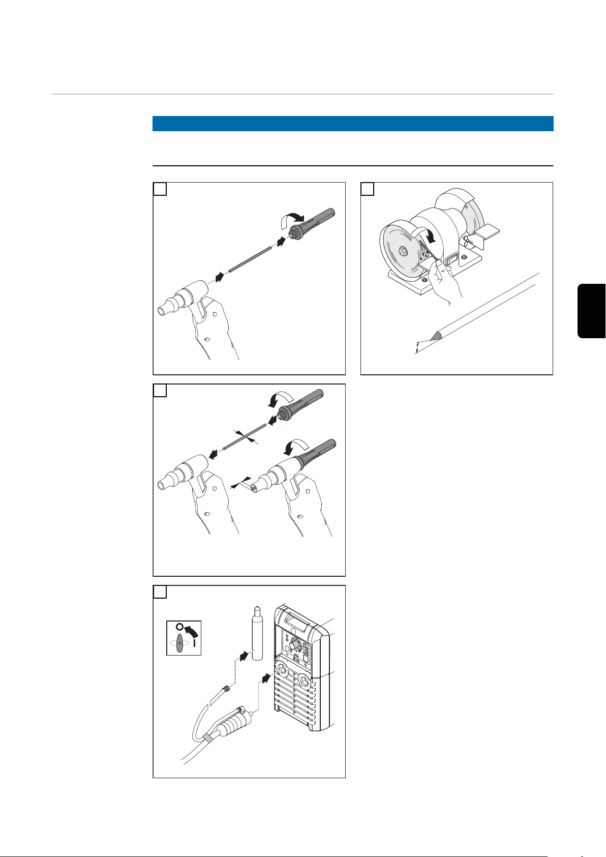
Inbetriebnahme
HINWEIS!
Vor jeder Inbetriebnahme den richtigen Sitz von Stromanschluss und Gasanschluss kontrollieren.
1
3
2
4
WIG Gasschieber-Schweißbrenner:
TTG 1600 / 2200 ... S
Betrieb möglich an folgenden Stromquellen:
TransPocket
-
TransPuls Synergic (außer CMT-
-
und Remote-Varianten)
5
Page 6

2
3
1
5
*
Gas
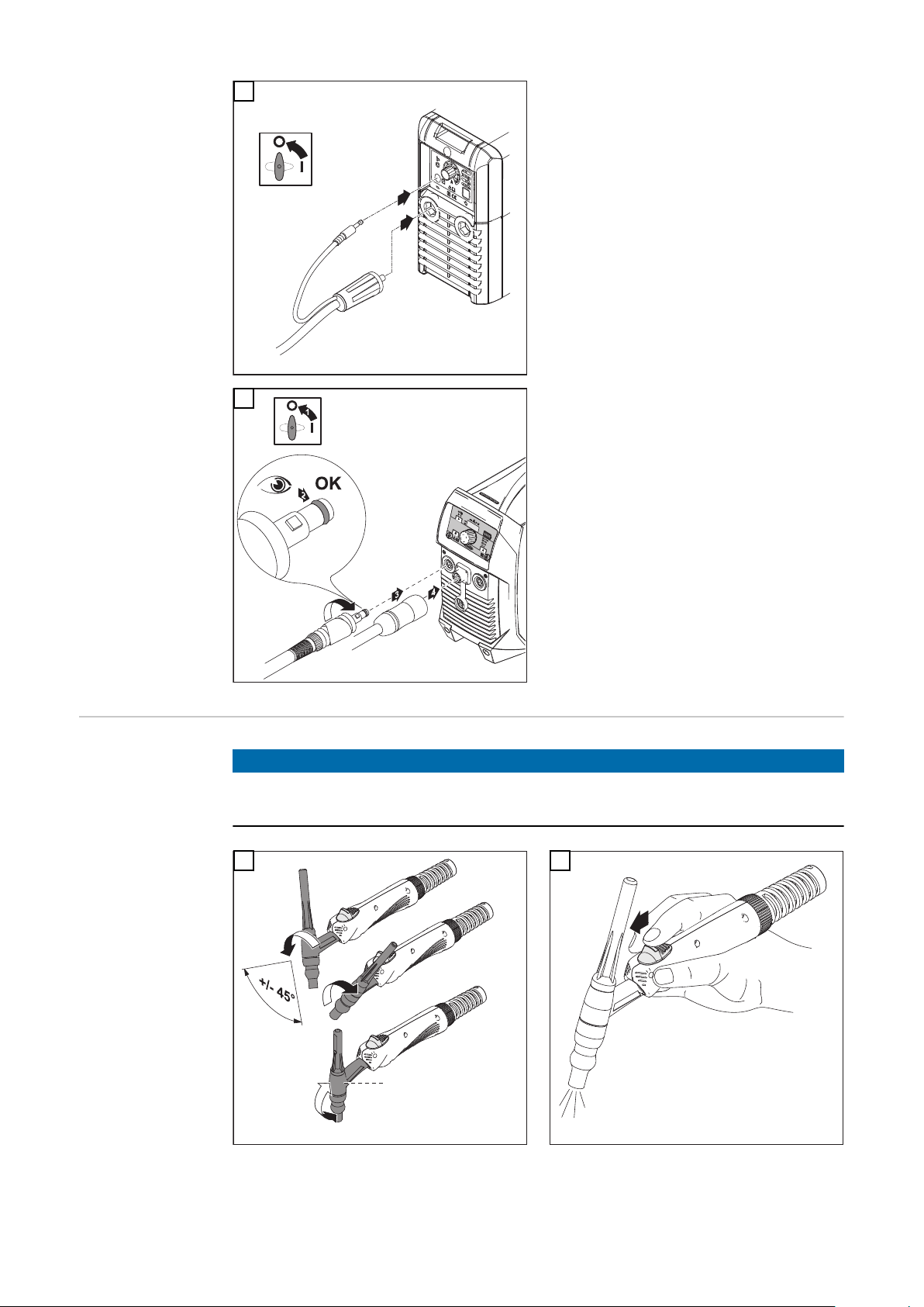
WIG Schweißbrenner mit Potentiometer: TTG 1600 ... Pot
Betrieb nur möglich an folgender
Stromquelle:
TransPocket 1500 TIG (Schutzgas
-
direkt an der Stromquelle anschließen)
WIG GasschieberSchweißbrenner
- S
6
WIG-Schweißbrenner: TTG 1600
FS/TL, TTG 1600 FS/UD
Betrieb nur möglich an folgender
Stromquelle:
AccuPocket 150/400 TIG (Schutz-
-
gas direkt an der Stromquelle anschließen)
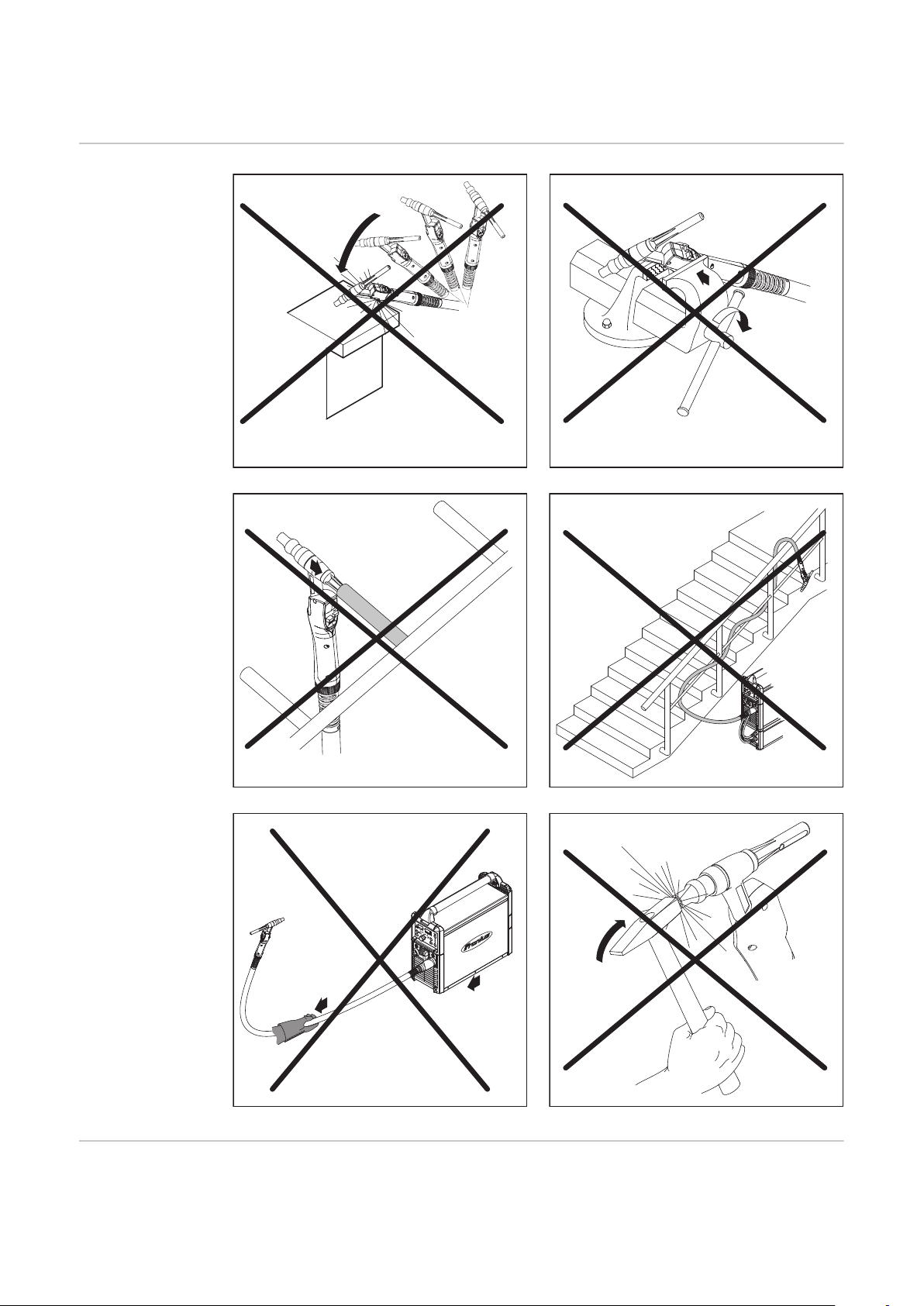
HINWEIS!
Häufiges Biegen der flexiblen Brenner kann zu dauerhaften Beschädigungen
führen.
1
* nur für Varianten „F“
2
6
Page 7

3
2
Gas
1
*
0 = min
9 = max
1
2
3
4
5
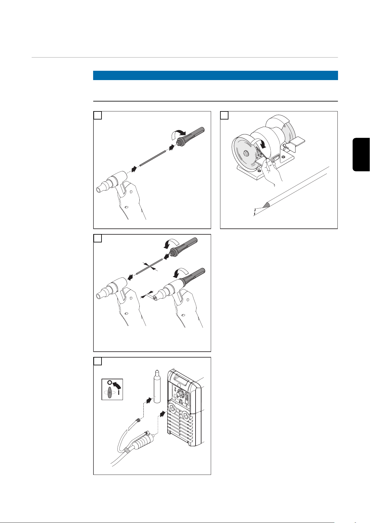
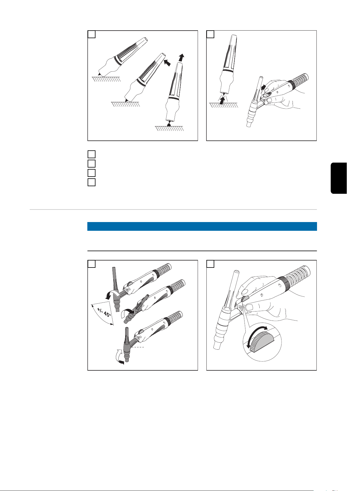
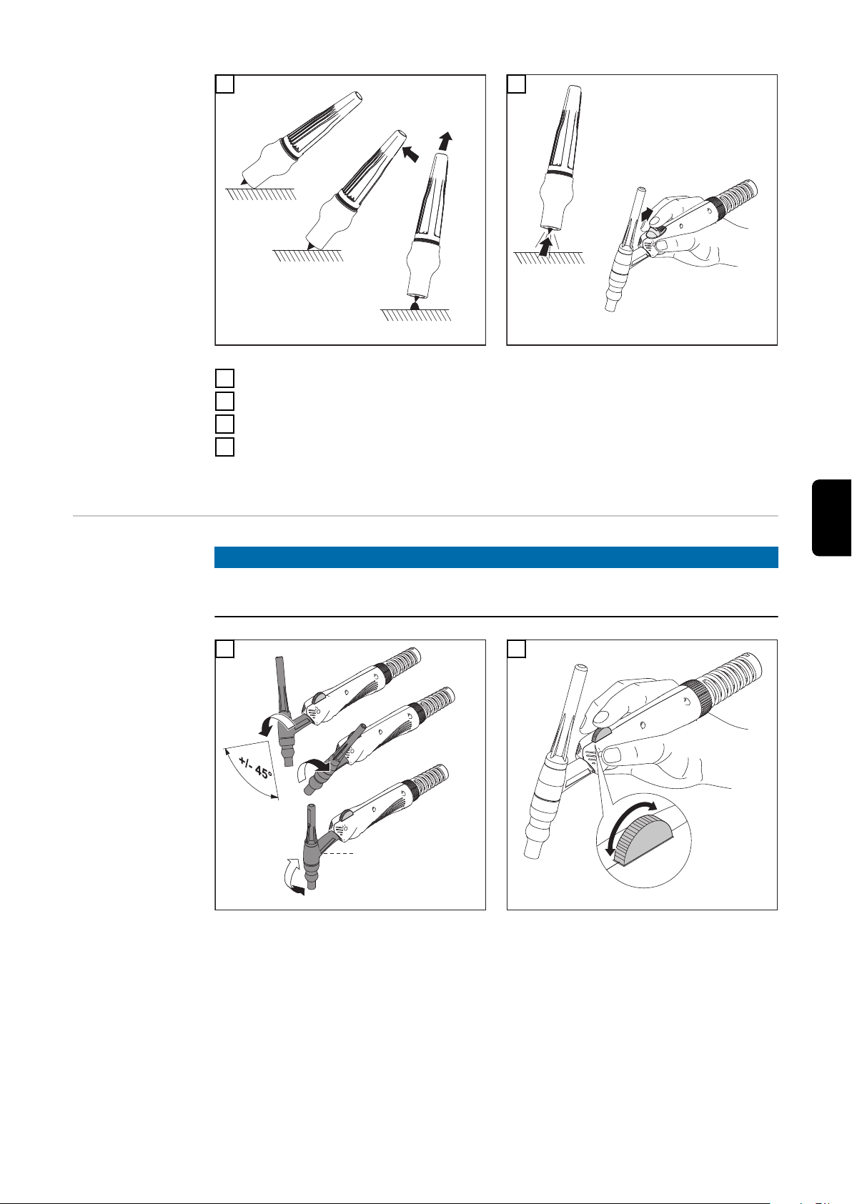
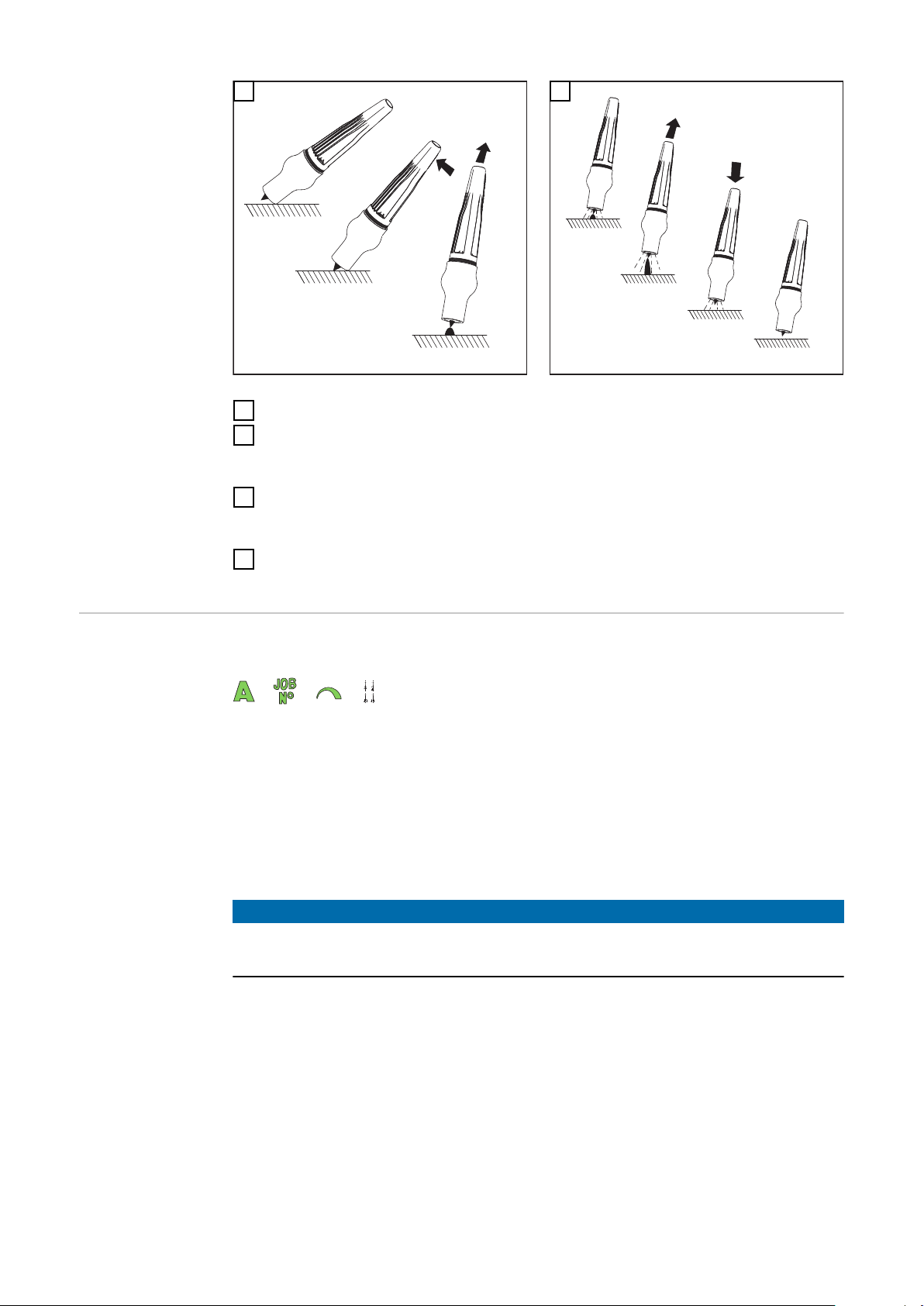
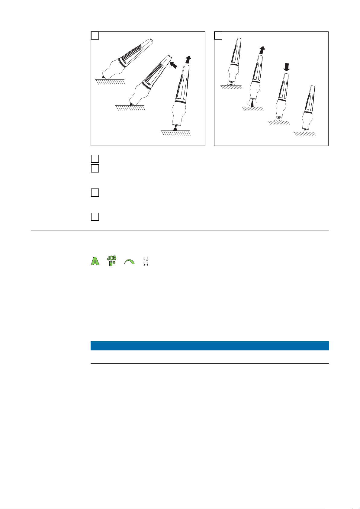
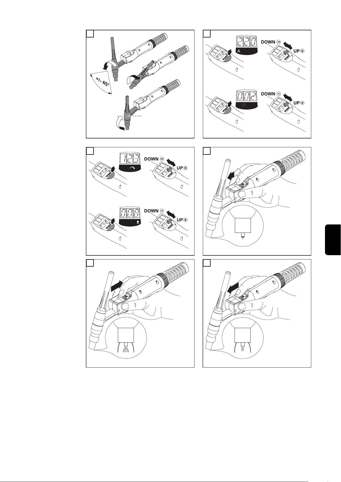
Schweißbrenner einrichten
1
Gasschieber öffnen: Gasströmung setzt ein
2
Berührungszünden
3
Schweißvorgang beenden:
4
Schweißbrenner abheben: Lichtbogen reißt ab
-
Gasschieber schließen
-
4
DE
WIGSchweißbrenner
mit Potentiometer - Pot
HINWEIS!
Häufiges Biegen der flexiblen Brenner kann zu dauerhaften Beschädigungen
führen.
1
* nur für Varianten „F“
2
7
Page 8

3
TCS
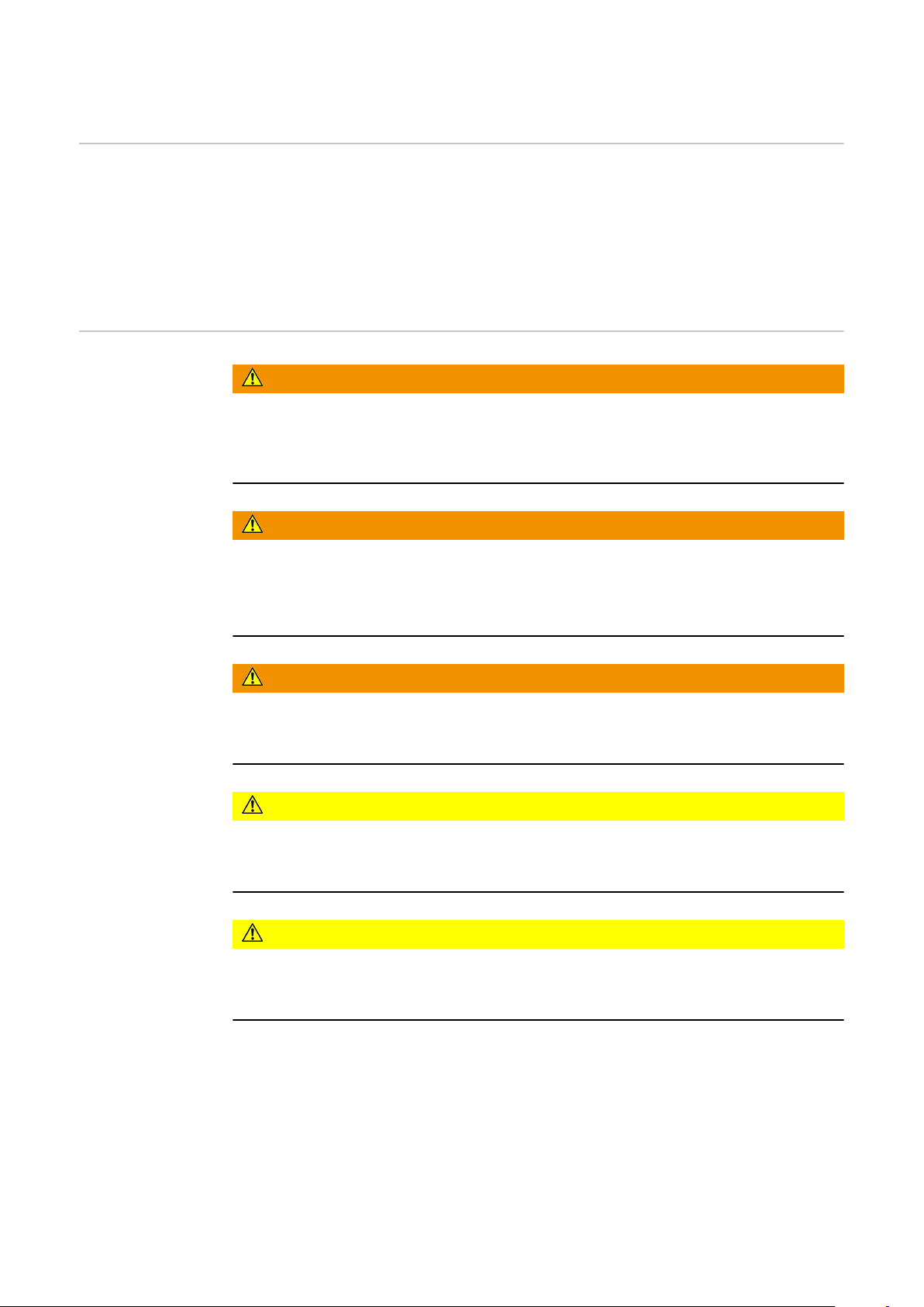
Schweißbrenner einrichten
1
Strom einstellen (auch während des Schweißvorganges möglich):
2
0 = min. Schweißstrom
-
9 = max. Schweißstrom
-
Werkstück mit Wolframelektrode berühren:
3
Gasströmung setzt aus
-
der Lichtbogen zündet
-
Beenden des Schweißvorganges mittels Funktion „TCS - TIG-Comfort-Stop“
4
4
(siehe Bedienungsanleitung TP 1500)
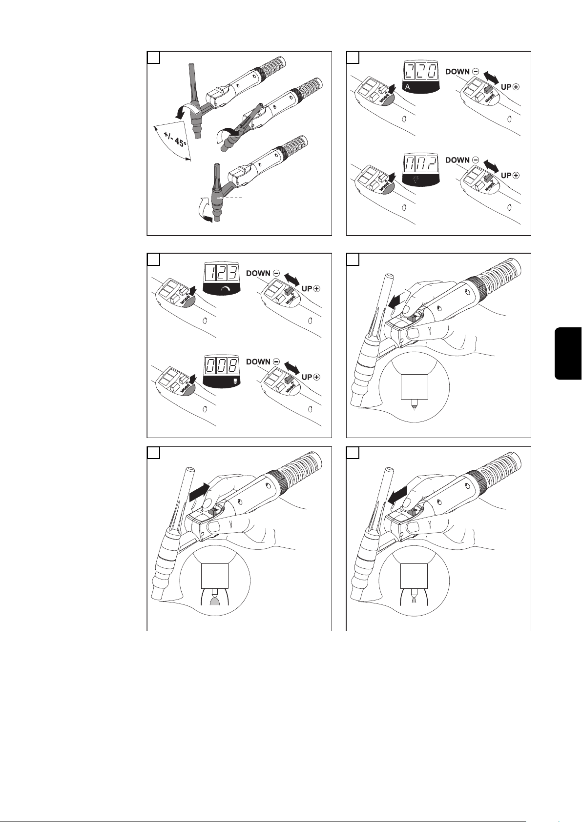
JobMaster TIG Mittels Taste „Mode“ einen der folgenden Parameter anwählen:
Parameter mittels Up/Down-Funktion einstellen
Voraussetzung für Kalottenbildung:
Verfahren „WIG-AC“
-
Voraussetzung für Zwischenabsenkung:
Betriebsart „Standard 4-Takt-Betrieb“
-
Setup-Parameter SFS auf „OFF“ (Werkseinstellung)
-
HINWEIS!
Häufiges Biegen der flexiblen Brenner kann zu dauerhaften Beschädigungen
führen (keine Garantieansprüche).
8
Page 9

*
1
+
-
1
+
-
2
+
-
1
+
-
2
l
1
l
2
* nur für Varianten „F“
3 4
2
DE
5
6
9
Page 10

Verschleißteil-
1
2
3
4
5
6
*
1
2
3
4
5
6
*
*
1
4
2
3
**
30°
2
1
d
d
3
1
d
2
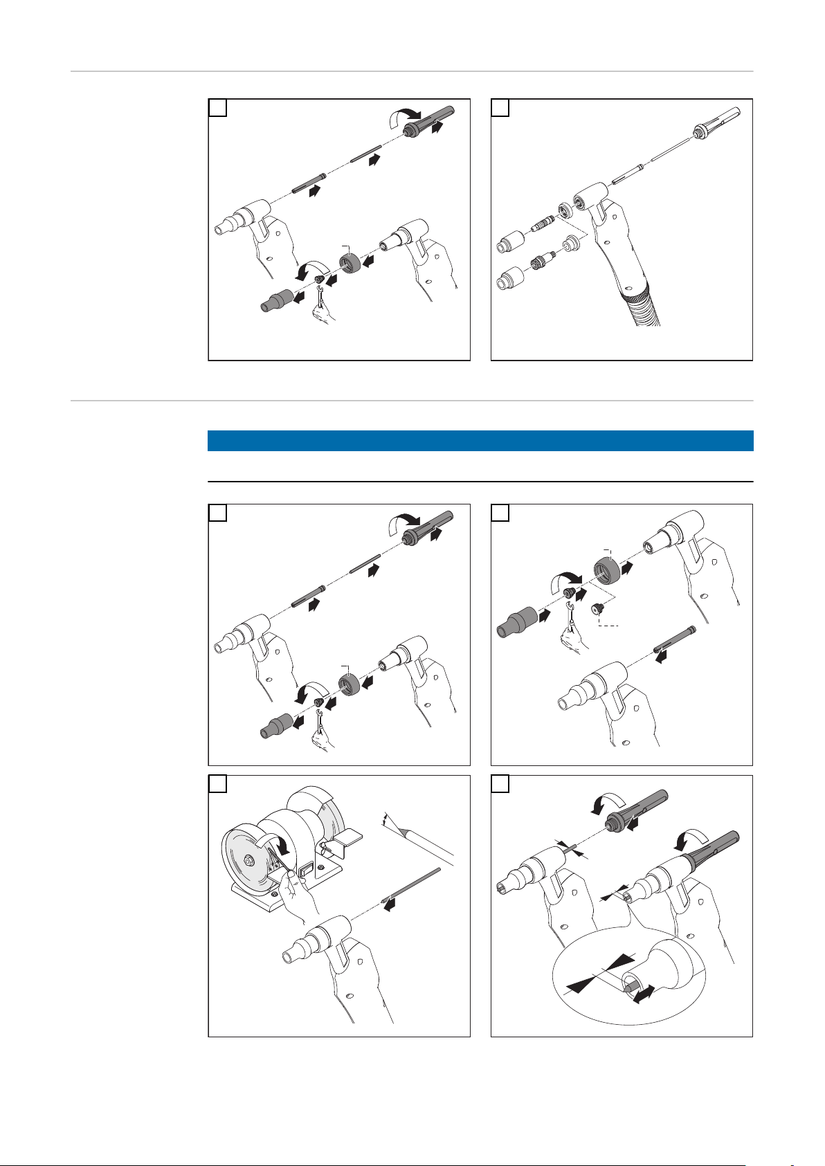
System
1
2
VerschleißteilSystem A
Verschleißteil-System A: Gasdüse gesteckt
Verschleißteil-System P: Gasdüse geschraubt
HINWEIS!
Gefahr der Beschädigung des Gewindes.
Spannmutter oder Gaslinse nur leicht festziehen.
1
2
3
4
10
Page 11

* Austauschbare Gummi-Dichthülse nur für TTG 2200 A
1
2
3
4
5
6
2
3
*
2
3
4
1
5
2
30°
1
d
d
3
1
d
2
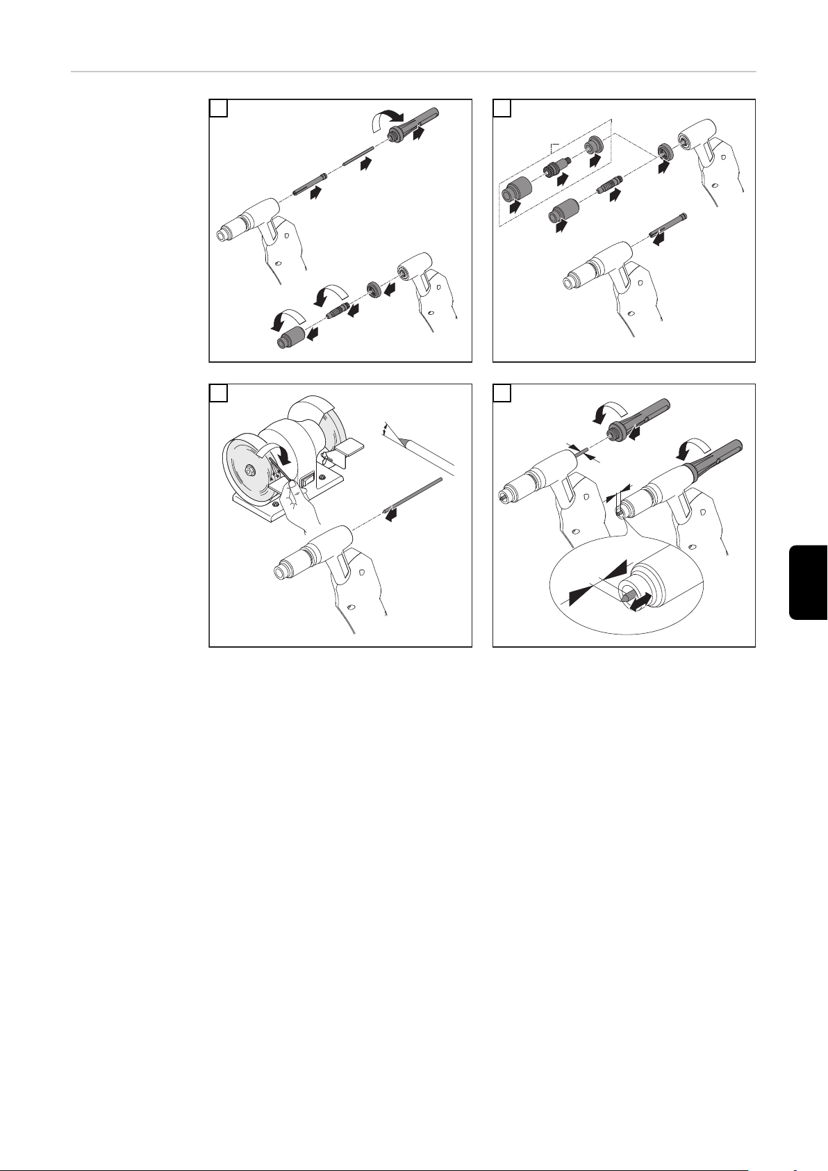
** Je nach Ausführung des Schweißbrenners kann anstelle der Spannmutter
eine Gaslinse zum Einsatz kommen
DE
VerschleißteilSystem P
1
2
* nur für Gaslinse
3
4
11
Page 12

Fehlerdiagnose, Fehlerbehebung
Fehlerdiagnose
Schweißbrenner lässt sich nicht anschließen
Ursache:
Behebung:
Kein Schweißstrom
Netzschalter eingeschaltet, Anzeigen an der Stromquelle leuchten, Schutzgas
vorhanden
Ursache:
Behebung:
Ursache:
Behebung:
Ursache:
Behebung:
Ursache:
Behebung:
keine Funktion des Potentiometers
Netzschalter eingeschaltet, Anzeigen an der Stromquelle leuchten, Schutzgas
vorhanden
Bajonett-Verriegelung verbogen
Bajonett-Verriegelung austauschen
Masseanschluss falsch
Masseanschluss und Klemme auf Polarität überprüfen
Stromkabel im Schweißbrenner unterbrochen
Brenner tauschen
Wolframelektrode lose
Wolframelektrode mittels Brennerkappe festziehen
Verschleißteile lose
Verschleißteile festziehen
Ursache:
Behebung:
kein Schutzgas
alle anderen Funktionen vorhanden
Ursache:
Behebung:
Ursache:
Behebung:
Ursache:
Behebung:
Ursache:
Behebung:
Ursache:
Behebung:
Steckerverbindungen „Potentiometer / Steuerleitung / Stromquelle“
fehlerhaft
Steckerverbindung überprüfen / Stromquelle oder Schweißbrenner
zum Service
Gasflasche leer
Gasflasche wechseln
Gasdruckminderer defekt
Gasdruckminderer tauschen
Gasschlauch nicht montiert oder schadhaft, geknickt
Gasschlauch montieren, ausbiegen oder tauschen
Schweißbrenner defekt
Schweißbrenner austauschen
Gas-Magnetventil defekt
Gas-Magnetventil austauschen
12
Page 13

schlechte Schweißeigenschaften
Ursache:
Behebung:
falsche Schweißparameter
Einstellungen überprüfen
DE
Ursache:
Behebung:
Schweißbrenner wird sehr heiß
Ursache:
Behebung:
Porosität der Schweißnaht
Ursache:
Behebung:
Ursache:
Behebung:
Ursache:
Behebung:
Ursache:
Behebung:
Masseanschluss falsch
Masseanschluss und Klemme auf Polarität überprüfen
Schweißbrenner zu schwach dimensioniert
Einschaltdauer und Belastungsgrenzen beachten
Spritzerbildung in der Gasdüse, dadurch unzureichender Gasschutz
der Schweißnaht
Schweißspritzer entfernen
Löcher im Schutzgas-Schlauch oder ungenaue Anbindung des
Schutzgas-Schlauches
Schutzgas-Schlauch austauschen
O-Ringe an den Anschlüssen sind zerschnitten oder defekt
O-Ringe austauschen
Feuchtigkeit / Kondensat in der Schutzgas-Leitung
Schutzgas-Leitung trocknen
Ursache:
Behebung:
Ursache:
Behebung:
Schlechte Zündeigenschaften
Ursache:
Behebung:
Ursache:
Behebung:
Gasdüse bekommt Risse
Ursache:
Behebung:
Zu starke oder zu geringe Schutzgas-Strömung
Schutzgas-Strömung korrigieren
Zu viel Trennmittel aufgetragen
Überschüssiges Trennmittel entfernen / weniger Trennmittel auftra-
gen
Ungeeignete Wolframelektrode (z.B. WP-Elektrode beim DCSchweißen)
Geeignete Wolframelektrode verwenden
Spannmutter, Gasdüse oder Spannhülse lose
Spannmutter, Gaslinse oder Spannhülse festziehen
Wolframelektrode ragt nicht weit genug aus der Gasdüse
Wolframelektrode weiter aus der Gasdüse ragen lassen
13
Page 14

Pflege, Wartung und Entsorgung
Pflege und War-
tung
Entsorgung Die Entsorgung nur gemäß den geltenden nationalen und regionalen Bestimmun-
gen durchführen.
14
Page 15

Technische Daten
DE
Schweißstrom bei
10 min / 40°C
(104°F)
DC
TTG 1600
gasgekühlt
I (Ampere) 15 % ED* 160
35 % ED* 110
60 % ED* 80
100 % ED* 60
Norm EN 439 EN 439
[mm (in.)] 1,0 - 3,2 (.039 - .126) 1,0 - 4,0 (.039 - .158)
[m (ft. + in.)] 4,0 / 8,0 (13 + 1.48 / 26 +
2.96)
ED* Einschaltdauer
Spannungsbemessung (V-Peak):
für handgeführte Schweißbrenner: 113 V
-
HINWEIS!
Gilt für die Schweißbrenner TTG 1600 A / A F: Die Schweißstrom-Angaben gelten bei Verwendung von Gasdüsen mit einer Länge von 33 mm.
Bei Verwendung von Gaslinsen und 22 mm-Gasdüsen reduzieren sich die
Schweißstrom-Angaben um bis zu 20 %.
TTG 2200 S
gasgekühlt
15 % ED* 220
35 % ED* 150
60 % ED* 110
100 % ED* 90
4,0 / 8,0 (13 + 1.48 / 26 +
2.96)
Das Produkt entspricht den Anforderungen laut Norm IEC 60974-7.
15
Page 16

16
Page 17

Contents
General 18
General remarks 18
Safety 18
Installation and commissioning 19
Commissioning 19
TIG gas valve welding torch - S 20
TIG welding torch with potentiometer - Pot 21
JobMaster TIG 22
Wearing-parts system 24
Wearing-parts system A 24
Wearing-parts system P 25
Troubleshooting 26
Fault diagnosis 26
Care, maintenance and disposal 28
Care and maintenance 28
Disposal 28
Technical data 29
EN
17
Page 18

General
General remarks The TIG gas valve welding torch (S) and the TIG welding torch with potentiome-
ter (Pot) are available in many versions and are suitable for welding CrNi and
steel.
The welding torches can be used in an extremely wide range of applications. They
are ideally suited for manual series production and one-off jobs, such as in workshops.
Safety
WARNING!
Work that is not carried out correctly can cause serious injury and damage.
The actions described herein may ONLY be carried out by skilled, trained technicians! Observe the instructions given in the attached document “Safety rules”.
WARNING!
An electric shock can be fatal.
Only carry out the actions described here if:
the mains switch of the power source is in the - O - position, and
▶
the power source has been disconnected from the mains.
▶
WARNING!
An electric shock can be fatal.
Before cleaning the welding torch and inspecting its components, shift the mains
switch of the power source into the - O - position.
CAUTION!
The torch becomes extremely hot during welding - risk of burns! Cleaning of the
welding torch, and inspection of its components, may only be carried out once
the torch has cooled down.
CAUTION!
Risk of injury from inadequate connections.
All cables, leads and hosepacks must be firmly attached, undamaged, properly
insulated and adequately.
18
Page 19

Installation and commissioning
1
2
3
0
°
1
2
d
d
3
2
3
1
Commissioning
NOTE!
Check that the current connection and the gas connection are properly secured
before use.
1
3
2
EN
4
TIG gas valve welding torch: TTG
1600/2200 ... S
Can be used with the following power
sources:
TransPocket
-
TransPuls Synergic (except CMT
-
and Remote versions)
19
Page 20

2
3
1
5
*
Gas
TIG welding torch with potentiometer:
TTG 1600 ... Pot
Can only be used with the following
power source:
TransPocket 1500 TIG (connect
-
shielding gas directly to the power
source)
TIG gas valve
welding torch - S
6
TIG welding torch with potentiometer::
TTG 1600 FS/TL, TTG 1600 FS/UD
Can only be used with the following
power source:
AccuPocket 150/400 TIG (con-
-
nect shielding gas directly to the
power source)
NOTE!
Frequent bending of the flexible burner can cause permanent damage.
1
2
* only on “F“ types
20
Page 21

3
2
Gas
1
*
0 = min
9 = max
1
2
3
4
5
Set up welding torch
1
Open gas valve: gas flow starts
2
Touchdown ignition
3
End the welding process:
4
Lift the welding torch clear: arc breaks
-
Close gas valve
-
4
EN
TIG welding
torch with potentiometer Pot
NOTE!
Frequent bending of the flexible burner can cause permanent damage.
1
* only on “F“ types
2
21
Page 22

3
TCS
Set up welding torch
1
Adjust current (may also be adjusted during the welding process):
2
0 = min. welding current
-
9 = max. welding current
-
Touch the workpiece with the tungsten electrode:
3
gas flow starts
-
Arc ignites
-
End welding using the „TCS - TIG-ComfortStop“ feature (see TP 1500 opera-
4
4
ting instructions)
JobMaster TIG Using the „Mode“ button select one of the following parameters:
Set the parameters using the Up/Down function
Cap-shaping - precondition:
TIG-AC welding process
-
Intermediate lowering - precondition:
Standard 4-step mode
-
Set-up parameter SFS must be set to “OFF” (factory setting)
-
NOTE!
Frequent bending of the flexible burner can cause permanent damage (no guarantee).
22
Page 23

*
1
+
-
1
+
-
2
+
-
1
+
-
2
l
1
l
2
* only on “F“ types
3 4
2
EN
5
6
23
Page 24

Wearing-parts
1
2
3
4
5
6
*
1
2
3
4
5
6
*
*
1
4
2
3
**
30°
2
1
d
d
3
1
d
2
system
1
2
Wearing-parts
system A
Wearing-parts system A: Plug-on gas nozzle
Wearing-parts system P: Screw-on gas nozzle
NOTE!
Risk of damage to the thread.
Tighten the clamping nut or gas lens only very gently.
1
2
3
4
24
Page 25

* interchangeable rubber sealing sleeve only on TTG 2200 A
1
2
3
4
5
6
2
3
*
2
3
4
1
5
2
30°
1
d
d
3
1
d
2
** Depending on the design of the welding torch, it may be possible to use a
gas lens instead of the clamping nut.
Wearing-parts
system P
1
2
EN
* only on gas lens
3
4
25
Page 26

Troubleshooting
Fault diagnosis
Welding torch cannot be connected
Cause:
Remedy:
No welding current
Mains switch ON, indicators on the power source are lit up, shielding gas flows
Cause:
Remedy:
Cause:
Remedy:
Cause:
Remedy:
Cause:
Remedy:
Potentiometer not working
Mains switch is on, indicators on the power source are lit, shielding gas available
Bayonet fixing bent
Replace bayonet fixing
Faulty earth (ground) connection
Check the earth (ground) connection and clamp for correct polarity
There is a break in the current cable in the welding torch
Change the torch
Loose tungsten electrode
Tighten tungsten electrode using torch cap
Loose parts
Tighten parts
Cause:
Remedy:
No protective gas shield
All other functions are OK
Cause:
Remedy:
Cause:
Remedy:
Cause:
Remedy:
Cause:
Remedy:
Cause:
Remedy:
Plug-in connections of „potentiometer/control line/power source“
faulty
Check plug-in connection/have power source or welding torch serviced
The gas cylinder is empty
Change the gas cylinder
The gas pressure regulator is faulty
Replace the gas pressure regulator
The gas hose is not connected, damaged or kinked
Connect/replace the gas hose, or straighten out kinks
The welding torch is faulty
Replace welding torch
Gas solenoid valve is faulty
Replace gas solenoid valve
26
Page 27

Poor weld properties
Cause:
Remedy:
Incorrect welding parameters
Check the settings
Cause:
Remedy:
The welding torch becomes very hot
Cause:
Remedy:
Weld-seam porosity
Cause:
Remedy:
Cause:
Remedy:
Cause:
Remedy:
Cause:
Remedy:
Grounding (earthing) connection is incorrect
Check the grounding (earthing) connection and terminal for correct
polarity
The design dimensions of the torch are not sufficient for this task
Respect the duty cycle and loading limits
Spatter accumulating in the gas nozzle, causing inadequate gas-shielding of the weld-seam
Remove the welding spatter
Either the shielding-gas hose has holes in it, or it is not connected up
properly
Change the shielding gas-hose
The O-ring seals on the connection points are cut or defective
Change the O-ring seals
Moisture / condensate in the shielding-gas hose
Dry the shielding-gas hose
EN
Cause:
Remedy:
Cause:
Remedy:
Poor ignition properties
Cause:
Remedy:
Cause:
Remedy:
Cracks in gas nozzle
Cause:
Remedy:
Shielding-gas flow is either too high or too low
Correct the shielding-gas flow
Too much parting agent applied
Wipe off excess parting agent / apply less parting agent
Unsuitable tungsten electrode (e.g. WP electrode for DC welding)
Use suitable tungsten electrode
Loose clamping nuts, gas lens or clamping sleeve
Tighten clamping nuts, gas lens or clamping sleeve
Tungsten electrode does not protrude far enough out of gas nozzle
Allow tungsten electrode to protrude further out of gas nozzle
27
Page 28

Care, maintenance and disposal
Care and maintenance
Disposal Dispose of in accordance with the applicable national and local regulations.
28
Page 29

Technical data
Welding current range at 10 min / 40°C
(104°F)
DC
TTG 1600
gas-cooled
I (Ampere) 15 % d.c.* 160
35 % d.c.* 110
60 % d.c.* 80
100 % d.c.* 60
Norm EN 439 EN 439
[mm (in.)] 1,0 - 3,2 (.039 - .126) 1,0 - 4,0 (.039 - .158)
[m (ft. + in.)] 4,0 / 8,0 (13 + 1.48 / 26 +
2.96)
d.c.* duty cycle
Voltage rating (V-Peak):
for manually guided torches: 113 V
-
NOTE!
When using TTG 1600 A / AF welding torches: the welding-amperage data apply
where 33 mm long gas nozzles are being used.
If gas lenses and 22 mm long gas nozzles are used, the welding-amperage data
are reduced by as much as 20 %.
TTG 2200 S
gas-cooled
15 % d.c.* 220
35 % d.c.* 150
60 % d.c.* 110
100 % d.c* 90
4,0 / 8,0 (13 + 1.48 / 26 +
2.96)
EN
The product complies with standard IEC 60974-7.
29
Page 30

30
Page 31

Sommaire
Généralités 32
Généralités 32
Sécurité 32
Installation et mise en service 33
Mise en service 33
Torche de soudage TIG avec vanne à gaz - S 34
Torche de soudage TIG avec potentiomètre - Pot 35
JobMaster TIG 36
Système de pièces d’usure 38
Système de pièces d’usure A 38
Système de pièces d’usure P 39
Diagnostic d’erreur, élimination de l'erreur 40
Diagnostic d'erreur 40
Maintenance, entretien et élimination 42
Entretien et maintenance 42
Élimination des déchets 42
Caractéristiques techniques 43
FR
31
Page 32

Généralités
Généralités La torche de soudage TIG avec vanne à gaz (S) et la torche de soudage TIG avec
potentiomètre (Pot) sont adaptées au soudage du CrNi et de l’acier et se distinguent par la diversité de leurs exécutions.
Ces torches de soudage conviennent pour les tâches les plus diverses et sont
idéales pour la fabrication manuelle en série et sur commande, ainsi que dans les
garages.
Sécurité
AVERTISSEMENT!
Les travaux mal exécutés peuvent entraîner de graves dommages corporels ou
matériels.
Seuls des techniciens spécialement formés par la société sont habilités à exécuter les procédures décrites ciaprès ! Veillez à respecter les indications fournies
dans le document ci-joint intitulé « Consignes de sécurité »..
AVERTISSEMENT!
Un choc électrique peut être mortel.
N’exécutez les procédures décrites que :
l’interrupteur d’alimentation de la source de courant est en position - O -
▶
et que la source de courant est débranchée.
▶
AVERTISSEMENT!
Un choc électrique peut être mortel.
Avant de procéder au nettoyage de la torche et à la vérification de ses composants, mettez l’interrup-teur d’alimentation de la source de courant en position O -.
32
ATTENTION!
Danger de brûlures pouvant être provoquées par la torche rendue extrêmement
chaude suite à son utilisation.
Ne procédez au nettoyage de la torche et à la vérification de ses composants que
lorsque celle-ci est refroidie.
ATTENTION!
Danger de blessures pouvant être provoquées par des connexions en mauvais
état.
Les câbles, conduites et faisceaux doivent être parfaitement fixés, en parfait
état, bien isolés, et correspondre aux dimensions requises.
Page 33

Installation et mise en service
1
2
3
0
°
1
2
d
d
3
2
3
1
Mise en service
REMARQUE!
Avant chaque mise en service, s’assurer que la connexion électrique et le raccordement de gaz sont bien fixés.
1
3
2
FR
4
Torche de soudage TIG avec vanne à
gaz : TTG 1600 / 2200 ... S
Fonctionnement possible sur les
sources de courant suivantes :
TransPocket
-
TransPuls Synergic (sauf procédés
-
CMT et Remote)
33
Page 34

2
3
1
5
*
Gas
Torche TIG avec potentiomètre : TTG
1600 ... Pot
Fonctionnement possible uniquement
sur la source de courant suivante :
TransPocket 1500 TIG (raccorder
-
le gaz protecteur directement sur
la source de courant)
Torche de soudage TIG avec vanne à gaz - S
6
Torche TIG : TTG 1600 FS/TL, TTG
1600 FS/UD
Fonctionnement possible uniquement
sur la source de courant suivante :
AccuPocket 150/400 TIG (raccor-
-
der le gaz protecteur directement
sur la source de courant)
REMARQUE!
Un pliage fréquent de la torche flexible peut provoquer des dommages
irrémédiables.
1
* uniquement pour les types «F»
2
34
Page 35

3
2
Gas
1
*
0 = min
9 = max
1
2
3
4
5
Positionner la torche de soudage
1
Ouvrir la vanne à gaz : le débit de gaz s’enclenche
2
Amorçage par contact
3
Terminer le processus de soudage :
4
Relever la torche de soudage : l’arc électrique s’interrompt
-
Fermer la vanne à gaz
-
4
FR
Torche de soudage TIG avec potentiomètre Pot
REMARQUE!
Un pliage fréquent de la torche flexible peut provoquer des dommages
irrémédiables.
1
* uniquement pour les types «F»
2
35
Page 36

3
TCS
Positionner la torche de soudage
1
Régler le courant (également possible durant le processus de soudage) :
2
0 = courant de soudage min.
-
9 = courant de soudage max.
-
Établir un contact entre l’électrode en tungstène et la pièce à usiner :
3
le débit de gaz s’enclenche
-
’arc électrique s’amorce
-
Terminer le processus de soudage à l’aide de la fonction „TCS - Tig-Comfort-
4
4
Stop“ (voir mode d’emploi TP 1500)
JobMaster TIG Au moyen de la gâchette „Mode“ sélectionnez l’un des paramètres suivants:
Configurez les paramètres au moyen de la fonction up/down
Formation de calotte - Condition:
Procédé soudage TIG-AC
-
Abaissement intermédiaire - Condition:
Service standard à 4 temps
-
Paramètre Setup SFS doit être mis sur «OFF» (réglage d’ usine)
-
REMARQUE!
Un pliage fréquent de la torche flexible peut provoquer des dommages
irrémédiables (aucune garantie).
36
Page 37

*
1
+
-
1
+
-
2
+
-
1
+
-
2
l
1
l
2
* uniquement pour les types «F»
3 4
2
FR
5
6
37
Page 38

Système de
1
2
3
4
5
6
*
1
2
3
4
5
6
*
*
1
4
2
3
**
30°
2
1
d
d
3
1
d
2
pièces d’usure
1
2
Système de
pièces d’usure A
Système de pièces d’usure A: tuyère à gaz
fichée
Système de pièces d’usure P: tuyère à gaz vissée
REMARQUE!
Danger d’endommagement du filetage.
Ne serrer que légèrement l’écrou de serrage ou la lentille de gaz.
1
2
3
4
38
Page 39

* manchon d’étanchéité en caoutchouc interchangeable uniquement pour
1
2
3
4
5
6
2
3
*
2
3
4
1
5
2
30°
1
d
d
3
1
d
2
TTG 2200 A
** En fonction du modèle de chalumeau, une lentille de gaz peut être utilisée
à la place de l’écrou de serrage.
Système de
pièces d’usure P
1
2
FR
* uniquement pour lentille de gaz
3
4
39
Page 40

Diagnostic d’erreur, élimination de l'erreur
Diagnostic d'erreur
Impossible de raccorder la torche de soudage
Cause:
Solution:
Pas de courant de soudage
Interrupteur d’alimentation enclenché, témoins de la source de courant allumés,
gaz de protection disponible
Cause:
Solution:
Cause:
Solution:
Cause:
Solution:
Cause:
Solution:
Le potentiomètre ne fonctionne pas
Interrupteur d’alimentation commuté, voyants allumés sur la source de courant,
gaz protecteur disponible
Le verrouillage baïonnette est tordu
Remplacer le verrouillage baïonnette
mauvaise connexion à la masse
vérifiez la polarité de la connexion à la masse et de la borne
coupure du câble électrique dans la torche
changez la torche
L’électrode en tungstène n’est pas fixée correctement
Fixer l’électrode en tungstène au moyen de l’extrémité de la torche
Les pièces d’usure sont desserrées
Resserrer les pièces d’usure
Cause:
Solution:
Pas de gaz de protection
Toutes les autres fonctions sont disponibles
Cause :
Remède :
Cause :
Remède :
Cause :
Remède :
Cause :
Remède :
Cause :
Remède :
Connexions „potentiomètre / câble de commande / source de courant“ défectueuses
Vérifier la fiche de connexion / Amener la source de courant ou la
torche de soudage au S.A.V.
Bouteille de gaz vide
Remplacer la bouteille de gaz
Détendeur défectueux
Remplacer le détendeur
Le tuyau de gaz n’est pas monté, est endommagé ou plié
Monter, détordre ou remplacer le tuyau de gaz
Torche défectueuse
Remplacer la torche de soudage
Électrovanne de gaz défectueuse
Remplacer l'électrovanne de gaz
40
Page 41

Mauvaises caractéristiques de soudage
Cause :
Remède :
Paramètres incorrects
Vérifier les réglages
Cause :
Remède :
La torche de soudage devient très chaude
Cause:
Solution:
Posrosité de la soudure
Cause :
Solution :
Cause :
Solution :
Cause :
Solution :
Cause :
Solution :
Connexion à la masse incorrecte
Vérifier la polarité de la connexion à la masse et de la borne
la torche n’a pas les dimensions suffisantes
respecter la durée maximale de fonctionnement et les limites de
charge
formation de projections dans la buse à gaz, d’où une protection gazeuse insuffisante de la soudure
enlevez les projections de soudure
trous dans le tuyau de gaz de protection ou mauvais raccordement de
ce même tuyau
changez le tuyau de gaz de protection
les joints toriques se trouvant au niveau des raccordements sont
coupés ou défectueux
changez les joints toriques
humidité ou condensation dans la conduite de gaz de protection
séchez la conduite de gaz de protection
FR
Cause :
Solution :
Cause :
Solution :
Mauvaises caractéristiques d’amorçage
Cause:
Solution:
Cause:
Solution:
La buse de gaz se fissure
Cause :
Solution :
courant trop faible ou trop important du gaz de protection
corrigez le courant du gaz de protection
vous avez utilisé une trop grande quantité d’antiagglomérant
enlevez l’excédent d’antiagglomérant / utilisez moins d’antiag-
glomérant
L’électrode en tungstène n’est pas adaptée (par ex. électrode WP
pour un soudage DC)
Utiliser une électrode en tungstène adaptée
L’écrou tendeur, la lentille de gaz ou la douille de serrage sont desserrés
Resserrer l’écrou tendeur, la lentille de gaz ou la douille de serrage
L'électrode en tungstène ne sort pas suffisamment de la buse de gaz
Faire davantage sortir l'électrode en tungstène de la buse de gaz
41
Page 42
Maintenance, entretien et élimination
Entretien et
maintenance
Élimination des
déchets
42
L'élimination doit être réalisée conformément aux prescriptions nationales et
régionales en vigueur.
Page 43
Caractéristiques techniques
Intensité de soudage
à
10 min / 40°C
(104°F)
DC
TTG 1600
refroidissement par gaz
I (Ampère) 15 % f.m.* 160
35 % f.m.* 110
60 % f.m.* 80
100 % f.m.* 60
Norme EN 439 EN 439
[mm (in.)] 1,0 - 3,2 (.039 - .126) 1,0 - 4,0 (.039 - .158)
[m (ft. + in.)] 4,0 / 8,0 (13 + 1.48 / 26 +
2.96)
f.m.* facteur de marche
Mesure de tension (V-Peak) :
pour les torches utilisées manuellement : 113 V
-
REMARQUE!
TTG 2200 S
refroidissement par gaz
15 % f.m.* 220
35 % f.m.* 150
60 % f.m.* 110
100 % f.m.* 90
4,0 / 8,0 (13 + 1.48 / 26 +
2.96)
FR
A observer pour les chalumeaux TTG 1600 A / AF: les indications de courant de
soudage sont valables en cas d’emploi de tuyères à gaz d’une longueur de 33
mm.
En cas d’utilisation de lentilles à gaz de tuyères à gaz de 22 mm, les indications
de courant de soudage diminuent de jusqu’à 20%.
Ce produit satisfait aux exigences de la norme IEC 60974-7.
43
Page 44

44
Page 45

Indice
In generale 46
In generale 46
Sicurezza 46
Installazione e messa in funzione 47
Messa in funzione 47
Torcia per saldatura TIG con valvola del gas - S 48
Torcia per saldatura TIG con potenziometro - Pot 49
JobMaster TIG 50
Sistema con pezzo sostituibile 52
Sistema con pezzo sostituibile A 52
Sistema con pezzo sostituibile P 53
Diagnosi e risoluzione degli errori 54
Diagnosi degli errori 54
Cura, manutenzione e smaltimento 56
Cura e manutenzione 56
Smaltimento 56
Dati tecnici 57
IT
45
Page 46
In generale
In generale Le torce per saldatura TIG con valvola del gas (S) e le torce per saldatura TIG
con potenziometro (Pot) sono adatte alla saldatura di CrNi e acciaio e si distinguono per la varietà delle versioni.
È possibile adattare le torce per saldatura alle lavorazioni più svariate e si dimostrano particolarmente efficaci nella produzione in serie e nella lavorazione singola
manuale, nonché nell’impiego nelle officine.
Sicurezza
PERICOLO!
I lavori effettuati in modo non corretto possono causare gravi danni alle persone
e alle cose.
Gli interventi descritti possono essere svolti soltanto dal personale specializzato!
Attenersi alle istruzioni contenute nel documento allegato „Norme di sicurezza“.
PERICOLO!
Uno schock elettrico può avere esiti mortali.
Effettuare gli interventi descritti soltanto se
l‘interruttore di rete della saldatrice è in posizione - O -
▶
la saldatrice è staccata dalla rete.
▶
PERICOLO!
Uno schock elettrico può avere esiti mortali.
La pulizia del cannello di saldatura e il controllo dei suoi componenti può avvenire soltanto quando l‘interruttore di rete della saldatrice è in posizione - O -.
PRUDENZA!
46
Pericolo di scottature a causa del forte riscaldamento del cannello durante il
funzionamento.
La pulizia del cannello di saldatura e il controllo dei suoi componenti può avvenire soltanto quando il cannello è freddo.
PRUDENZA!
Pericolo di danni personali per insufficienza di collegamenti.
Tutti i cavi, i condotti e i tubi devono essere solidi, integri, isolati e adeguatamente dimensionati.
Page 47
Installazione e messa in funzione
1
2
3
0
°
1
2
d
d
3
2
3
1
Messa in funzione
AVVERTENZA!
Prima di ogni messa in funzione controllare il corretto posizionamento del collegamento elettrico e dell’attacco del gas.
1
3
2
IT
4
Torcia per saldatura TIG con valvola
del gas:: TTG 1600 / 2200 ... S
Possibilità di funzionamento con i generatori seguenti:
TransPocket
-
TransPuls Synergic (escluse le ver-
-
sioni CMT e Remote)
47
Page 48

2
3
1
5
*
Gas
Torcia per saldatura TIG con potenziometro: TTG 1600 ... Pot
Possibilità di funzionamento solo con i
generatori seguenti:
TransPocket 1500 TIG (collegare il
-
gas inerte direttamente al generatore)
Torcia per saldatura TIG con valvola del gas - S
6
Torcia per saldatura TIG:: TTG 1600
FS/TL, TTG 1600 FS/UD
Possibilità di funzionamento solo con i
generatori seguenti:
AccuPocket 150/400 TIG (colle-
-
gare il gas inerte direttamente al
generatore)
AVVERTENZA!
La frequente piegatura della torcia flessibile può provocare danni duraturi.
1
2
* solo per varianti „F“
48
Page 49

3
2
Gas
1
*
0 = min
9 = max
1
2
3
4
5
Installare la torcia per saldatura
1
Aprire la valvola del gas: il flusso del gas ha inizio
2
Accensione a contatto
3
Terminare il processo di saldatura:
4
sollevare la torcia per saldatura: l’arco voltaico si spegne
-
chiudere la valvola del gas
-
4
IT
Torcia per saldatura TIG con potenziometro Pot
AVVERTENZA!
La frequente piegatura della torcia flessibile può provocare danni duraturi.
1
* solo per varianti „F“
2
49
Page 50

3
TCS
Installare la torcia per saldatura
1
Regolare la corrente (è possibile anche durante il processo di saldatura):
2
0 = corrente di saldatura min.
-
9 = corrente di saldatura max.
-
Mettere a contatto il pezzo da lavorare con l’elettrodo al tungsteno:
3
il flusso del gas ha inizio
-
l’arco voltaico si accende
-
Terminare il processo di saldatura con la funzione „TCS - TIG Comfort Stop“
4
4
(vedere le istruzioni per l’uso TP 1500)
JobMaster TIG Mediante il tasto „Mode“ selezionare uno dei seguenti parametri della fuente de
corriente:
Regolare i parametri mediante funzione up/down
Formazione della calotta - condizione necessaria:
Sistema di saldatura TIG-AC
-
Intervallo mediante - Condizione necessaria:
Funzionamento standard a 4 tempi
-
Parametro SFS si trova su „OFF“ (regolazione in fabbrica)
-
AVVERTENZA!
La frequente piegatura della torcia flessibile può provocare danni duraturi
(nessuna garanzia).
50
Page 51

*
1
+
-
1
+
-
2
+
-
1
+
-
2
l
1
l
2
2
* solo per varianti „F“
3 4
5
IT
6
51
Page 52

Sistema con pez-
1
2
3
4
5
6
*
1
2
3
4
5
6
*
*
1
4
2
3
**
30°
2
1
d
d
3
1
d
2
zo sostituibile
1
2
Sistema con pezzo sostituibile A
Sistema con pezzo sostituibile A: Applicare
l‘ugello del gas
Sistema con pezzo sostituibile P: Avvitare l‘ugello del gas
AVVERTENZA!
Pericolo di danno alla filettatura.
Stringere il dado di tensione e il limitatore del gas solo leggermente.
1
2
3
4
52
Page 53

* manicotto impermeabile in gomma sostituibile solo per TTG 2200 A
1
2
3
4
5
6
2
3
*
2
3
4
1
5
2
30°
1
d
d
3
1
d
2
** A seconda della versione del cannello di saldatura, si può utilizzare al pos-
to del dado di tensione un limitatore del gas.
Sistema con pezzo sostituibile P
1
2
IT
* solo per limitatore del gas
3
4
53
Page 54

Diagnosi e risoluzione degli errori
Diagnosi degli
errori
Impossibile collegare il cannello di saldatura
Causa:
Risoluzione:
Corrente di saldatura assente
L‘interruttore di rete è acceso, le spie della saldatrice sono accese, il gas inerte è
presente
Causa:
Risoluzione:
Causa:
Risoluzione:
Causa:
Risoluzione:
Causa:
Risoluzione:
Nessuna funzione del potenziometro
Interruttore di rete inserito, spie sul generatore accese, gas inerte presente
La chiusura a baionetta si deforma
Sostituire la chiusura a baionetta
collegamento a massa sbagliato
controllare le polarità del collegamento a massa e il morsetto
il cavo di corrente nel cannello di saldatura è interrotto
sostituire il cannello
Elettrodo al tungsteno puro allentato
Fissare l’elettrodo al tungsteno puro tramite la chiusura del
cannello
Pezzi soggetti a usura allentati
Fissare i pezzi soggetti a usura
Causa:
Risoluzione:
Gas inerte assente
Tutte le altre funzioni sono disponibili.
Causa:
Risoluzione:
Causa:
Risoluzione:
Causa:
Risoluzione:
Causa:
Risoluzione:
Causa:
Risoluzione:
Collegamenti a spina „Potenziometro / Cavo di comando / Generatore“ difettosi
Controllare i collegamenti a spina / Inviare il generatore o la
torcia per saldatura all’Assistenza
bombola del gas vuota.
sostituire la bombola del gas.
riduttore di pressione del gas difettoso.
sostituire il riduttore di pressione del gas.
il tubo del gas è smontato, danneggiato, piegato.
montare, sostituire, raddrizzare il tubo del gas.
torcia per saldatura guasta.
sostituire la torcia per saldatura.
valvola magnetica del gas difettosa.
sostituire la valvola magnetica del gas.
54
Page 55

Proprietà di saldatura scarse
Causa:
Risoluzione:
Parametri di saldatura errati.
Controllare le impostazioni.
Causa:
Risoluzione:
Il cannello di saldatura diventa molto caldo
Causa:
Risoluzione:
Porosità del giunto saldato
Causa:
Risoluzione:
Causa:
Risoluzione:
Causa:
Risoluzione:
Causa:
Risoluzione:
Collegamento a massa errato.
Controllare la polarità del collegamento a massa e del morset-
to.
cannello di saldatura sottodimensionato
rispettare il tempo d’accensione e i limiti di carico
formazione di spruzzi nell‘ugello del gas perciò insufficiente
protezione con il gas del giunto saldato
eliminare gli spruzzi di saldatura
fori nel tubo del gas inerte o allacciamento insufficiente del tubo del gas inerte
sostituire il tubo del gas inerte
le guarnizioni OR degli attacchi sono rovinate o difettose
sostituire le guarnizioni OR
umidità / condensato nel tubo del gas inerte
asciugare il tubo del gas inerte
IT
Causa:
Risoluzione:
Causa:
Risoluzione:
Proprietà d’accensione non efficaci
Causa:
Risoluzione:
Causa:
Risoluzione:
L'ugello del gas si crepa
Causa:
Risoluzione:
flusso troppo forte o debole del gas inerte
correggere il flusso del gas inerte
e‘ stato applicato troppo agente distaccante
eliminare l‘agente distaccante in eccesso / applicare meno
agente distaccante
Elettrodo al tungsteno puro non adatto (ad esempio, elettrodo
WP per saldatura DC)
Utilizzare un elettrodo al tungsteno puro adatto
Dado di bloccaggio, limitatore del gas o bussola di serraggio allentati
Fissare il dado di bloccaggio, il limitatore del gas o la bussola di
serraggio
l'elettrodo al tungsteno non sporge abbastanza sull'ugello del
gas.
far sporgere maggiormente l'elettrodo al tungsteno sull'ugello
del gas.
55
Page 56

Cura, manutenzione e smaltimento
Cura e manutenzione
Smaltimento Lo smaltimento va eseguito unicamente nel rispetto delle disposizioni nazionali e
regionali vigenti.
56
Page 57

Dati tecnici
Corrente di saldatura
a
10 min / 40°C
(104°F)
DC
TTG 1600
raffreddato a gas
I (Ampere) 15 % TA* 160
35 % TA* 110
60 % TA* 80
100 % TA* 60
Norma EN 439 EN 439
[mm (in.)] 1,0 - 3,2 (.039 - .126) 1,0 - 4,0 (.039 - .158)
[m (ft. + in.)] 4,0 / 8,0 (13 + 1.48 / 26 +
2.96)
TA* tempo di accensione
Taratura della tensione (V-Peak):
per cannelli di saldatura manuali: 113 V
-
AVVERTENZA!
TTG 2200 S
raffreddato a gas
15 % TA* 220
35 % TA* 150
60 % TA* 110
100 % TA* 90
4,0 / 8,0 (13 + 1.48 / 26 +
2.96)
IT
Per i cannelli di saldatura TTG 1600 A / AF attenzione: I dati relativi alla corrente di saldatura valgono se si utilizzano ugelli a gas della lunghezza di 33 mm.
Se si usano delle lenti gas e ugelli a gas da 22 mm i valori relativi alla corrente di
saldatura si abbassano fino al 20 %.
Questo prodotto è conforme allo standard IEC 60974-7.
57
Page 58

58
Page 59

Tabla de contenido
Generalidades 60
Generalidades 60
Seguridad 60
Instalación y puesta en servicio 61
Colocação em funcionamento 61
Antorcha de soplete TIG - S 62
Antorcha TIG con potenciómetro - Pot 63
JobMaster TIG 64
Sistema de desgaste 66
Sistema de desgaste A 66
Sistema de desgaste P 67
Diagnóstico de errores, solución de errores 68
Diagnóstico de errores 68
Cuidado, mantenimiento y eliminación 70
Cuidado y mantenimiento 70
Eliminación 70
Datos técnicos 71
ES
59
Page 60

Generalidades
Generalidades Las antorchas de soplete TIG (S) y las antorchas TIG con potenciómetro (Pot) re-
sultan adecuadas para la soldadura de CrNi y acero y se caracterizan por la variedad de sus versiones.
Las antorchas se pueden adaptar a los más diferentes planteamientos de las
tareas y muestran sus ventajas de forma óptima en la producción manual en serie
e individual, así como en el ámbito de los talleres.
Seguridad
¡PELIGRO!
Los trabajos realizados defectuosamente pueden causar daños personales y
materiales graves.
¡Las actividades descritas sólo deben ser realizadas por personal técnico formado! Tenga en cuenta el documento adjuntado „Normas de seguridad.
¡PELIGRO!
Un electrochoque puede ser mortal.
Realizar las actividades descritas sólo cuando:
el interruptor de red de la fuente de corriente se encuentre en posición - O -
▶
la fuente de corriente esté desconectada de la red.
▶
¡PELIGRO!
Un electroschock puede ser mortal.
Antes de la limpieza del soplete para soldar y de comprobar sus componentes,
colocar el interruptor de red de la fuente de corriente en posición - O -.
¡PRECAUCIÓN!
60
Riesgo de quemadura como consecuencia del soplete utilizado y altamente calentado.
La limpieza del soplete y la comprobación de sus componentes, sólo deberá realizarse estando este refrigerado.
¡PRECAUCIÓN!
Riesgo de lesión a través de conexiones insuficientes.
Todos los cables, tuberías y paquetes de latiguillos tienen que estar fijos, aislados
sin deterioros y suficientemente dimensionados.
Page 61
Instalación y puesta en servicio
1
2
3
0
°
1
2
d
d
3
2
3
1
Colocação em
funcionamento
¡OBSERVACIÓN!
Antes de cada colocação em funcionamento controlar o assento correto da
conexão de corrente e da conexão de gás.
1
3
2
ES
4
Tocha TIG-corrediça de gás: TTG
1600 / 2200 ... S
Possibilidade de operação com as seguintes fontes de solda:
TransPocket
-
TransPuls Synergic (exceto Varian-
-
te e Remota CMT)
61
Page 62
2
3
1
5
*
Gas
Tocha-TIG com potenciômetro: TTG
1600 ... Pot
Possibilidade de operação somente nas
seguintes fontes de solda:
TransPocket 1500 TIG (gás inerte
-
conectar diretamente na fonte de
solda)
Antorcha de soplete TIG - S
6
Antorcha TIG con: TTG 1600 FS/TL,
TTG 1600 FS/UD
Posibilidad de servicio sólo en la siguiente fuente de corriente:
AccuPocket 150/400 TIG (conec-
-
tar el gas protector directamente
en la fuente de corriente)
¡OBSERVACIÓN!
Un doblado frecuente de las antorchas flexibles puede provocar daños de
carácter permanente.
1
* sólo para variantes “F“
2
62
Page 63
3
2
Gas
1
*
0 = min
9 = max
1
2
3
4
5
Preparar la antorcha
1
Abrir el soplete: El flujo de gas comienza
2
Cebado por contacto
3
Finalizar el proceso de soldadura:
4
Elevar la antorcha: El arco voltaico se interrumpe
-
Cerrar el soplete
-
4
ES
Antorcha TIG
con potenciómetro - Pot
¡OBSERVACIÓN!
Un doblado frecuente de las antorchas flexibles puede provocar daños de
carácter permanente.
1
* sólo para variantes “F“
2
63
Page 64

3
TCS
Preparar la antorcha
1
Ajustar la corriente (también es posible durante el proceso de soldadura):
2
0 = min. corriente de soldadura
-
9 = max. corriente de soldadura
-
Tocar la pieza de trabajo con el electrodo de tungsteno:
3
El flujo de gas comienza
-
El arco voltaico se enciende
-
Finalizar el proceso de soldadura mediante la función „TCS - Tig-Comfort-
4
4
Stop“ (ver el manual de instrucciones TP 1500)
JobMaster TIG Por medio de la pulsador „Mode“ seleccionar uno de los siguientes parámetros en
la fuente de corriente:
Ajustar los parámetros por medio de la función Up/Down
Formación de calota - condición previa:
Procedimiento de soldadura TIG-A
-
Reducción intermedia - condición previa:
Operación estándar de 4 tiempos
-
Parámetro de configuración SFS debe estar en “OFF“ (ajuste de fábrica)
-
¡OBSERVACIÓN!
Un doblado frecuente de las antorchas flexibles puede provocar daños de
carácter permanente (no hay garantia).
64
Page 65

*
1
+
-
1
+
-
2
+
-
1
+
-
2
l
1
l
2
* sólo para variantes “F“:
3 4
2
ES
5
6
65
Page 66

Sistema de des-
1
2
3
4
5
6
*
1
2
3
4
5
6
*
*
1
4
2
3
**
30°
2
1
d
d
3
1
d
2
gaste
1
2
Sistema de desgaste A
Sistema de desgaste A: Inyector de gas insertado
Sistema de desgaste P: Inyector de gas roscado
¡OBSERVACIÓN!
Riesgo de dañar la rosca.
Apretar sólo ligeramente la tuerca de sujeción resp. la lente gaseosa.
1
2
3
4
66
Page 67

* manguito obturador intercambiable sólo para TTG 2200 A
1
2
3
4
5
6
2
3
*
2
3
4
1
5
2
30°
1
d
d
3
1
d
2
** Dependiendo del modelo del soplete para soldar, en lugar de la tuerca de
sujeción se puede utilizar una lente gaseosa.
Sistema de desgaste P
1
2
ES
* sólo para lente gaseosa
3
4
67
Page 68

Diagnóstico de errores, solución de errores
Diagnóstico de
errores
No se puede conectar la antorcha
Causa:
Solución:
Sin corriente de soldadura
Interruptor de red conectado, las indicaciones en la fuente de corriente se iluminan, existe gas protector
Causa:
Solución:
Causa:
Solución:
Causa:
Solución:
Causa:
Solución:
No hay función del potenciómetro
Interruptor de red conectado, indicaciones en la fuente de corriente iluminadas,
gas protector disponible
El bloqueo de bayoneta está deformado
Sustituir el bloqueo de bayoneta
Conexión a masa defectuosa
Comprobar la polaridad de la conexión a masa y del contacto
Cable de corriente en el soplete de soldadura interrumpido
Cambiar soplete
El electrodo de tungsteno está suelto
Apretar el electrodo de tungsteno por medio de la caperuza de
antorcha
Las piezas de desgaste están sueltas
Apretar las piezas de desgaste
Causa:
Solución:
No hay gas protector
Todas las demás funciones están disponibles
Causa:
Solución:
Causa:
Solución:
Causa:
Solución:
Causa:
Solución:
Causa:
Solución:
Uniones enchufables „Potenciómetro/cable de control/fuente de corriente“ defectuosas
Comprobar la unión enchufable/enviar la fuente de corriente o la
antorcha al servicio
Bombona de gas vacía
Cambiar la bombona de gas
Regulador de presión de gas defectuoso
Cambiar el regulador de presión de gas
Manguera de gas no montada, dañada o doblada
Montar, redoblar o cambiar la manguera de gas
Antorcha defectuosa
Sustituir la antorcha
Electroválvula de gas defectuosa
Sustituir la electroválvula de gas
68
Page 69

Propiedades de soldadura pobres
Causa:
Solución:
Parámetros de soldadura incorrectos.
Comprobar los ajustes.
Causa:
Solución:
El soplete se caliente demasiado
Causa:
Solución:
Porosidad del cordón de soldadura
Causa:
Solución:
Causa:
Solución:
Causa:
Solución:
Causa:
Solución:
Conexión de masa errónea.
Comprobar la polaridad de la conexión de masa y del borne.
Dimensiones insuficientes del soplete
Observar la duración de ciclo de trabajo y los límites de carga
Formación de proyecciones en la boquilla de gas, a través de ello,
protección de gas insuficiente del cordón de soldadura
Eliminar las proyecciones de soldadura
Agujeros en el tubo flexible de gas protector o conexión del tubo fle-
xible de gas no exacta
Cambiar el tubo flexible de gas
Las juntas tóricas de las conexiones están cortadas o defectuosas
Cambiar juntas tóricas
Humedad / Condensación en la tubería de gas protector
Secar la tubería de gas protector
ES
Causa:
Solución:
Causa:
Solución:
Pobres propiedades de cebado
Causa:
Solución:
Causa:
Solución:
La tobera de gas se está agrietando.
Causa:
Solución:
Corriente de gas muy débil o muy fuerte
Corregir la corriente del gas protector
Se ha aplicado demasiado agente separador
Eliminar el agente separador sobrante / aplicar menos agente separa-
dor
Electrodo de tungsteno inadecuado (por ejemplo, electrodo WP para
soldadura DC)
Utilizar un electrodo de tungsteno adecuado
Tuerca tensora, lente de gas o casquillo tensor suelto
Apretar la tuerca tensora, la lente de gas o el casquillo tensor
El electrodo de tungsteno no sobresale suficientemente de la tobera
de gas.
Dejar que el electrodo de tungsteno sobresalga más de la tobera de
gas.
69
Page 70

Cuidado, mantenimiento y eliminación
Cuidado y mantenimiento
Eliminación Efectuar la eliminación observando las normas nacionales y regionales aplica-
bles.
70
Page 71

Datos técnicos
Corriente de soldadura
con
10 min / 40°C (104°F)
DC
DC* Duración de ciclo de trabajo
Dimensionado de tensión (V-Peak):
-
¡OBSERVACIÓN!
Para los sopletes TTG 1600 A / AF observar: Las indicaciones de corriente de
soldadura se aplican al utilizar inyectores de gas con una longitud de 33 mm.
Al utilizar lentes gaseosas y inyectores de gas con una longitud de 22 mm las indicaciones de corriente de soldadura se reducen en hasta un 20 %.
TTG 1600
refrigerador por gas
I (Ampere) 15 % DC* 160
35 % DC* 110
60 % DC* 80
100 % DC* 60
Norm EN 439 EN 439
[mm (in.)] 1,0 - 3,2 (.039 - .126) 1,0 - 4,0 (.039 - .158)
[m (ft. +
in.)]
para soplete de guiado manual: 113 V
4,0 / 8,0 (13 + 1.48 / 26 +
2.96)
TTG 2200 S
refrigerador por gas
15 % DC* 220
35 % DC* 150
60 % DC* 110
100 % DC* 90
4,0 / 8,0 (13 + 1.48 / 26 +
2.96)
ES
El producto cumple los requisitos de la norma IEC 60974-7.
71
Page 72

72
Page 73

Índice
Informações gerais 74
Informações gerais 74
Segurança 74
Instalação e colocação em funcionamento 75
Comissionamento 75
Tocha de válvula de gás TIG - S 76
Tocha TIG com o potenciômetro - Pot 77
JobMaster TIG 78
Sistema de peça de desgaste 80
Sistema de peça de desgaste A 80
Sistema de peça de desgaste P 81
Diagnóstico de erro, eliminação de erro 82
Diagnóstico de Falhas 82
Conservação, Manutenção e Descarte 84
Conservação e manutenção 84
Descarte 84
Dados técnicos 85
PT-BR
73
Page 74
Informações gerais
Informações gerais
Segurança
A tocha de válvula de gás TIG (S) e a tocha de solda TIG com potenciômetro
(Pot) são adequadas para a soldagem de CrNi e aço e se destacam pelas versões
variadas.
As tochas de solda podem ser adaptadas às mais diferentes tarefas e dão bons
resultados na produção manual em série e individual, assim como na área de oficinas.
PERIGO!
Trabalhos executados de forma incorreta podem causar danos graves a pessoas
e materiais.
As atividades descritas a seguir deverão ser executadas apenas por pessoal
técnico formado! Respeite o documento em anexo „Diretrizes de segurança“.
PERIGO!
Um choque elétrico pode ser fatal.
Executar as atividades descritas somente se:
o interruptor de rede da fonte de solda estiver na posição - O -
▶
a fonte de solda estiver desligada da rede.
▶
PERIGO!
Um choque elétrico pode ser fatal.
Antes de efetuar a limpeza da tocha de solda e a verificação dos seus componentes, colocar o interruptor da fonte de solda na posição - O -.
CUIDADO!
Perigo de queimadura devido à operação com a tocha de solda muito aquecida.
Efetuar a limpeza da tocha de solda e a verificação dos seus componentes
apenas quando a mesma estiver fria.
CUIDADO!
Perigo de lesão devido a ligações insuficientes.
Todos os cabos, tubagens e jogos de mangueiras devem estar fixos, intactos, isolados e ter dimensões adequadas.
74
Page 75

Instalação e colocação em funcionamento
1
2
3
0
°
1
2
d
d
3
2
3
1
Comissionamento
AVISO!
Antes de cada comissionamento, controlar o assento correto da conexão de corrente e da conexão de gás inerte.
1
3
2
PT-BR
4
Tocha de válvula de gás TIG: TTG
1600 / 2200 ... S
Possibilidade de operação com as seguintes fontes de solda:
TransPocket
-
TransPuls Synergic (exceto Varian-
-
te e Remota CMT)
75
Page 76

2
3
1
5
*
Gas
Tocha TIG com potenciômetro: TTG
1600 ... Pot
Possibilidade de operação somente nas
seguintes fontes de solda:
TransPocket 1500 TIG (conectar o
-
gás de proteção diretamente à fonte de solda)
Tocha de válvula
de gás TIG - S
6
Tocha TIG: TTG 1600 FS/TL, TTG
1600 FS/UD
Possibilidade de operação somente nas
seguintes fontes de solda:
AccuPocket 150/400 TIG (conec-
-
tar o gás de proteção diretamente
à fonte de solda)
AVISO!
Flexão constante das tochas de solda flexíveis pode causar danificações permanentes.
1
* somente para as versões „F“
2
76
Page 77
3
2
Gas
1
*
0 = min
9 = max
1
2
3
4
5
Ajustar a tocha de solda
1
Abrir a corrediça de gás: Inicia-se o fluxo de gás
2
Ignição de contato
3
Término do processo de soldagem:
4
Levantar a tocha de solda: o arco voltaico se rompe
-
Fechar a válvula de gás
-
4
Tocha TIG com o
potenciômetro Pot
AVISO!
Flexão constante das tochas de solda flexíveis pode causar danificações permanentes.
1
* somente para as versões „F“
2
PT-BR
77
Page 78
3
TCS
Ajustar a tocha de solda
1
Ajustar a corrente (também possível durante o processo de soldagem):
2
0 = corrente de soldagem mín.
-
9 = corrente de soldagem máx.
-
Tocar a peça de trabalho com o eletrodo de tungstênio:
3
o fornecimento de gás é suspenso
-
o arco voltaico entra em ignição
-
Finalizar o processo de soldagem através da função „TCS - TIG-Comfort-
4
4
Stop“ (vide manual de instruções TP 1500)
JobMaster TIG Através da tecla „Mode“, selecione um dos seguintes parâmetros:
Ajustar o parâmetro através da função up/down
Pré-requisito para a formação de calota:
Método de soldagem „TIG-CA“
-
Pré-requisito para a redução intermediária:
Modo de operação „Operação de 4 ciclos padrão“
-
Parâmetro Setup SFS em „OFF“ (configuração de fábrica)
-
AVISO!
Flexão constante das tochas de solda flexíveis pode causar danificações permanentes (sem reivindicação de garantia).
78
Page 79
*
1
+
-
1
+
-
2
+
-
1
+
-
2
l
1
l
2
* somente para as versões „F“
3 4
2
PT-BR
5
6
79
Page 80

Sistema de peça
1
2
3
4
5
6
*
1
2
3
4
5
6
*
*
1
4
2
3
**
30°
2
1
d
d
3
1
d
2
de desgaste
1
2
Sistema de peça
de desgaste A
Sistema de peça de desgaste A: Bico de gás
conectado
Sistema de peça de desgaste P: Bico de gás parafusado
AVISO!
Perigo de dano da rosca.
Apertar a porca de aperto ou a lente de gás levemente.
1
2
3
4
80
Page 81

* Luva de vedação de borracha substituível somente para TTG 2200 A
1
2
3
4
5
6
2
3
*
2
3
4
1
5
2
30°
1
d
d
3
1
d
2
** Dependendo da versão da tocha de solda, ao invés da porca de aperto po-
de ser usada uma lente de gás
Sistema de peça
de desgaste P
1
2
* somente para lente de gás
3
4
PT-BR
81
Page 82

Diagnóstico de erro, eliminação de erro
Diagnóstico de
Falhas
Não é possível conectar a tocha de solda
Causa:
Solução:
Sem corrente de soldagem
Interruptor da rede ligado, indicações acesas na fonte de solda, gás de proteção
disponível
Causa:
Solução:
Causa:
Solução:
Causa:
Solução:
Causa:
Solução:
sem função do potenciômetro
Interruptor da rede ligado, indicações acesas na fonte de solda, gás de proteção
disponível
Fecho da baioneta dobrado
Substituir o fecho da baioneta
Conexão de massa incorreta
Verificar a conexão de massa e o borne de conexão quanto à pola-
ridade
Cabo de corrente na tocha de solda interrompido
Substituir a tocha de solda
Eletrodo de tungstênio solto
Apertar o eletrodo de tungstênio com a capa da tocha
Peças de desgaste soltas
Apertar peças de desgaste
Causa:
Solução:
Sem gás de proteção
Todos as outras funções existentes
Causa:
Eliminação:
Causa:
Eliminação:
Causa:
Eliminação:
Causa:
Eliminação:
Causa:
Eliminação:
Conectores „potenciômetro / linha de controle / fonte de solda“ defeituosos
Verificar conectores / fonte de solda ou tocha de solda para o serviço
Cilindro de gás vazio
Substituir o cilindro de gás
Redutor de pressão de gás com defeito
Substituir o redutor de pressão de gás
Mangueira de gás não montada ou com defeito, dobrada
Montar, desentortar ou trocar a mangueira de gás
Tocha de solda com defeito
Substituir a tocha de solda
Válvula solenóide de gás com defeito
Substituir a válvula solenóide de gás
82
Page 83

Características de soldagem ruins
Causa:
Solução:
Parâmetros de soldagem incorretos
Verificar os ajustes
Causa:
Solução:
A tocha de solda esquenta muito
Causa:
Solução:
Porosidade na costura de soldagem
Causa:
Solução:
Causa:
Solução:
Causa:
Solução:
Causa:
Solução:
Conexão de massa incorreta
Verificar a conexão de massa e o borne quanto à polaridade
Tocha de solda dimensionada muito fraca
Observar o ciclo de trabalho e os limites de carga
Formação de respingos no bico de gás, por isso a proteção de gás da
costura de soldagem é insuficiente
Remover os respingos de solda
Furos na mangueira do gás de proteção ou conexão inadequada da
mangueira de gás de proteção
Substituir a mangueira do gás de proteção
Os O-Rings nas conexões estão cortados ou com defeito
Substituir O-Rings
Umidade / condensado na tubulação de gás de proteção
Secar a tubulação de gás de proteção
PT-BR
Causa:
Solução:
Causa:
Solução:
Características ruins de ignição
Causa:
Solução:
Causa:
Solução:
Rachadura no bico de gás
Causa:
Solução:
Fluxo de gás de proteção forte ou fraco demais
Corrigir o fluxo de gás de proteção
Aplicação de agente separador em excesso
Retirar o agente separador em excesso / aplicar menos agente sepa-
rador
Eletrodo de tungstênio inadequado (por ex., eletrodo WP na soldagem CC)
Utilizar um eletrodo de tungstênio adequado
Porca de aperto, bico de gás ou luva de fixação soltos
Apertar porca de aperto, lente de gás ou luva de fixação
O eletrodo de tungstênio não está longe o suficiente do bico de gás
Afastar o eletrodo de tungstênio do bico de gás
83
Page 84

Conservação, Manutenção e Descarte
Conservação e
manutenção
Descarte O descarte pode ser executado somente de acordo com as determinações nacio-
nais e regionais em vigor.
84
Page 85

Dados técnicos
Corrente de soldagem a
10 min / 40°C
(104°F)
CC
TTG 1600
refrigerado a gás
I (ampère) 15 % CT* 160
35 % CT* 110
60 % CT* 80
100 % CT* 60
Norma EN 439 EN 439
[mm (in.)] 1,0 - 3,2 (.039 - .126) 1,0 - 4,0 (.039 - .158)
[m (ft. + in.)] 4,0 / 8,0 (13 + 1.48 / 26 +
2.96)
CT* Ciclo de trabalho
Medição da tensão (pico V):
para tochas de solda manuais: 113 V
-
AVISO!
TTG 2200 S
refrigerado a gás
15 % CT* 220
35 % CT* 150
60 % CT* 110
100 % CT* 90
4,0 / 8,0 (13 + 1.48 / 26 +
2.96)
PT-BR
Válido para as tochas de solda TTG 1600 A / A F: As indicações da corrente de
soldagem são válidas para o uso de bicos de gás com um comprimento de 33
mm.
No caso de uso de lentes de gás e bicos de gás de 22 mm, as indicações da corrente de soldagem diminuem em até 20%.
O produto está em conformidade com as exigências da norma IEC 60974-7.
85
Page 86

86
Page 87

目录
概述 88
一般说明 88
安全说明 88
安装和调试 89
调试 89
TIG 气阀焊枪 - S 90
带有电位计的 TIG 焊枪 - Pot 91
JobMaster TIG 92
成套易损件 94
成套易损件 A 94
成套易损件 P 95
错误诊断和错误排除 96
错误诊断 96
维护、保养和废料处理 98
维修与保养 98
废料处理 98
技术数据 99
ZH
87
Page 88

概述
一般说明 TIG 气阀焊枪 (S) 和带电位计的 TIG 焊枪 (Pot) 有多种版本可供选择,适用于焊接 CrNi 和
钢。
焊枪的应用范围十分广泛。它们非常适合在车间等场合执行手动连续生产以及一次性作
业。
安全说明
危险!
操作不当可能会造成严重的人身伤害和设备损坏。此处介绍的操作只能由技术熟练、经专
业培训的技术人员执行!请遵守随附文档“安全规程”中提供的说明。
危险!
电击可能致命。仅在以下几种情况下才能执行操作:
电源主开关位于 - O - 位置,且
▶
电源与输电干线的连接断开。
▶
危险!
电击可能致命。在清洁焊枪及检查其部件之前,请先将电源主开关切换至 - O - 位置。
小心!
在焊接过程中,焊枪会变得非常热 - 存在烫伤的危险!只能在焊枪冷却后,才能清洁焊枪
和检查其部件。
小心!
连接不良可能会造成人身伤害。所有电缆、引线及其他综合管线必须连接牢固、完好无
损、妥善和充分绝缘。
88
Page 89

安装和调试
1
2
3
0
°
1
2
d
d
3
2
3
1
调试
注意!
使用前,先检查通电接口和通气接口是否稳固连接。
1
3
2
ZH
4
TIG 气阀焊枪:TTG 1600/2200 ...S
可与下列电源配合使用:
-
TransPocket
-
TransPuls Synergic(CMT 和 Remote
型号除外)
89
Page 90

2
3
1
5
*
Gas
带有电位计的 TIG 焊枪:TTG 1600 ...Pot
只能与下列电源配合使用:
-
TransPocket 1500 TIG(将保护气体
直连至电源)
TIG 气阀焊枪 - S
6
注意!
频繁折弯挠性燃烧器会造成永久性损坏。
1
带有电位计的 TIG 焊枪:TTG 1600 FS/
TL、TTG 1600 FS/UD
只能与下列电源配合使用:
-
AccuPocket 150/400 TIG(将保护气
体直连至电源)
2
* 仅针对“F”类型
90
Page 91

3
2
Gas
1
*
0 = min
9 = max
1
2
3
4
5
设置焊枪
1
打开气阀:气流开始流动
2
接触式引弧
3
结束焊接过程:
4
-
抬起焊枪:断弧
-
关闭气阀
4
带有电位计的 TIG
焊枪 - Pot
注意!
频繁折弯挠性燃烧器会造成永久性损坏。
1
* 仅针对“F”类型
ZH
2
91
Page 92
3
TCS
设置焊枪
1
调节电流(也可以在焊接过程中调节):
2
-
0 = 最小焊接电流
-
9 = 最大焊接电流
将工件与钨极接触:
3
-
气流开始流动
-
电弧起燃
通过“TCS - TIG-ComfortStop”功能结束焊接(请参见 TP 1500 操作说明)
4
4
JobMaster TIG 使用“模式”按钮选择下列其中一个参数:
使用 Up/Down(上/下)功能设置参数
形成截球形 - 前提条件:
-
TIG-AC 焊接工艺
中间降低 - 前提条件:
-
标准四脉冲模式
-
设置参数 SFS 必须设为“OFF”(关)(出厂设置)
注意!
频繁折弯挠性燃烧器会造成永久性损坏(不保证)。
92
Page 93
*
1
+
-
1
+
-
2
+
-
1
+
-
2
l
1
l
2
* 仅针对“F”类型
3 4
2
ZH
5
6
93
Page 94
成套易损件
1
2
3
4
5
6
*
1
2
3
4
5
6
*
*
1
4
2
3
**
30°
2
1
d
d
3
1
d
2
1
2
成套易损件 A
成套易损件 A:插接式气体喷嘴
成套易损件 P:螺丝拧入式气体喷嘴
注意!
存在螺纹损坏的风险。只需轻轻用力即可拧紧夹紧螺母或气体透镜。
1
2
3
* 可替换的橡胶密封套仅针对 TTG 2200 A
** 根据焊枪设计,可以使用气体透镜来替代夹紧螺母。
4
94
Page 95
成套易损件 P
1
2
3
4
5
6
2
3
*
2
3
4
1
5
2
30°
1
d
d
3
1
d
2
1
2
* 仅针对气体透镜
3
4
ZH
95
Page 96

错误诊断和错误排除
错误诊断
无法连接焊枪
原因:
补救措施:
无焊接电流
主开关处于“打开”状态,电源上的指示灯点亮,保护气体流动
原因:
补救措施:
原因:
补救措施:
原因:
补救措施:
原因:
补救措施:
电位计不能正常工作
主开关处于打开状态,电源上的指示灯点亮,保护气体可用
卡口式固定件折弯
更换卡口式固定件
接地连接存在故障
检查接地连接和地线夹的极性是否正确
焊枪中的载流电缆损坏
更换焊枪
钨极松动
使用焊枪盖帽拧紧钨极
部件松动
拧紧部件
原因:
补救措施:
无保护气体
所有其他功能可用
原因:
措施:
原因:
措施:
原因:
措施:
原因:
措施:
原因:
措施:
焊枪性能差
原因:
措施:
“电位计/控制线/电源”的插入式连接存在故障
检查插入式连接/检修电源或焊枪
气瓶空了
更换气瓶
保护气流量计损坏
更换保护气流量计
气管未安装或受损,弯折
安装、拉直或更换气管
焊枪损坏
更换焊枪
气体磁阀损坏
更换气体磁阀
焊接参数错误
检查设置
96
原因:
措施:
接地连接错误
检查接地连接并检查接线夹极性
Page 97

焊枪变得很热
原因:
补救措施:
焊缝多孔
原因:
补救措施:
焊枪的设计尺寸不能胜任这样的任务
遵守占空比和负载的限制要求
焊渣在气体喷嘴处累积,造成焊缝保护气体不充分
清除焊渣
原因:
补救措施:
原因:
补救措施:
原因:
补救措施:
原因:
补救措施:
原因:
补救措施:
引弧性能差
原因:
补救措施:
原因:
补救措施:
保护气体软管上有孔洞,或其未正确连接
更换保护气体软管
连接点处的 O 形密封圈有切口或存在缺陷
更换 O 形密封圈
保护气体软管内有湿气 / 冷凝水
风干保护气体软管
保护气体流量过高或过低
校正保护气体流量
使用的分离剂过多
除去多余的分离剂 / 使用少量的分离剂
钨极不合适(例如,对于直流焊接使用 WP 电极)
使用合适的钨极
夹紧螺母、气体透镜或夹紧套管松动
拧紧夹紧螺母、气体透镜或夹紧套管
ZH
气体喷嘴上存在裂纹
原因:
补救措施:
钨极从气体喷嘴中伸出的长度不够长
让钨极从气体喷嘴中伸出的长度再长一些
97
Page 98

维护、保养和废料处理
维修与保养
废料处理 按照国家和地区的现行法规对废料进行处理。
98
Page 99

技术数据
10 min / 40°C (104°F)
时的焊接电流范围
DC
TTG 1600
气冷式
I (A) 15 % d.c.*160
35 % d.c.*110
60 % d.c.*80
100 % d.c.*60
标准 EN 439 EN 439
[mm (in)] 1.0 - 3.2 (0.039 - 0.126) 1.0 - 4.0 (0.039 - 0.158)
[m (ft + in)] 4.0 / 8.0 (13 + 1.48 / 26 + 2.96) 4.0 / 8.0 (13 + 1.48 / 26 + 2.96)
d.c.* 占空比
额定电压(峰值电压):
-
对于手动操作焊枪:113 V
TTG 2200 S
气冷式
15 % d.c.*220
35 % d.c.*150
60 % d.c.*110
100 % d.c* 90
注意!
使用 TTG 1600 A / AF 焊枪时:如果使用的是 33 mm 长的气体喷嘴,则上述焊接电流数据
适用。如果使用了气体透镜和 22 mm 长的气体喷嘴,焊接电流数据会减小多达 20 %。
本产品符合 IEC 60974-7 标准。
ZH
99
Page 100

 Loading...