


Operating
instructions
TransSteel 3500 Syn
TransSteel 5000 Syn
Operating instructions
EN
42,0426,0258,EN 017-02052022


Contents
Safety rules 7
Explanation of safety notices 7
General 7
Proper use 8
Environmental conditions 8
Obligations of the operator 8
Obligations of personnel 8
Mains connection 9
Protecting yourself and others 9
Danger from toxic gases and vapours 10
Danger from flying sparks 10
Risks from mains current and welding current 11
Meandering welding currents 12
EMC Device Classifications 12
EMC measures 12
EMF measures 13
Specific hazards 13
Requirement for the shielding gas 14
Danger from shielding gas cylinders 14
Danger from escaping shielding gas 15
Safety measures at the installation location and during transport 15
Safety measures in normal operation 16
Commissioning, maintenance and repair 16
Safety inspection 17
Disposal 17
Safety symbols 17
Data protection 17
Copyright 17
EN
General information 19
General 21
Device concept 21
Functional principle 21
Application areas 21
Warning notices on the device 21
Welding processes, procedures and welding characteristics for MIG/MAG welding 23
General 23
Welding characteristics 23
Summary of MIG/MAG standard synergic welding 23
Short description of arc air gouging 23
System components 24
General 24
Safety 24
Overview 24
Options 26
General 26
Machine interface 26
Gas preheater CO2 connection 26
Keylock switch 27
VRD: safety function 27
VRD: safety principle 28
Control elements and connections 29
Synergic control panel 31
General 31
Safety 31
Synergic control panel 32
Service parameters 35
3

Keylock 36
Connections, switches and mechanical components 37
TSt 3500/5000 Syn power source 37
Installation and commissioning 39
Minimum equipment needed for welding task 41
General 41
Gas-cooled MIG/MAG welding 41
MIG/MAG welding, water-cooled 41
MMA welding 41
Before installation and commissioning 42
Safety 42
Utilisation for intended purpose only 42
Setup regulations 42
Mains connection 43
Connecting the mains cable 44
Safety 44
General 44
Stipulated mains cables and strain-relief devices 44
Connecting the mains cable 45
Fitting the Europe strain-relief device 45
Fitting the Canada/US strain-relief device 46
Generator-powered operation 48
Generator-powered operation 48
Start-up 49
General 49
Information on system components 49
Assembling the system components (overview) 49
Placing the wirefeeder on the power source 50
Fitting the interconnecting hosepack strain-relief device 51
Connecting the interconnecting hosepack 51
Connecting the gas cylinder 52
Establishing a ground earth connection 53
Connecting MIG/MAG welding torches 54
Inserting/replacing feed rollers 54
Inserting the wirespool 55
Inserting the basket-type spool 56
Feeding in the wire electrode 57
Setting the contact pressure 59
Adjusting the brake 59
Design of the brake 60
Welding 61
Power limitation 63
Safety function 63
MIG/MAG modes 64
General 64
Symbols and their explanations 64
2-step mode 65
4-step mode 65
Special 4-step mode 66
Spot welding 66
2-step stitch welding 67
4-step stitch welding 67
MIG/MAG welding 68
Safety 68
Preparatory work 68
Overview 68
MIG/MAG standard synergic welding 69
MIG/MAG standard synergic welding 69
Corrections during welding 70
4

MIG/MAG standard manual welding 71
General 71
Available parameters 71
MIG/MAG standard manual welding 71
Corrections during welding 72
Spot and stitch welding 73
General 73
Spot welding 73
Stitch welding 74
EasyJob mode 76
General 76
Storing EasyJob operating points 76
Retrieving EasyJob operating points 76
Deleting EasyJob operating points 76
Retrieving EasyJob operating points on the Up/Down welding torch 76
MMA welding 78
Safety 78
Preparation 78
MMA welding 78
Corrections during welding 79
HotStart function 80
Anti-stick function 80
Arc Air Gauging (TSt 5000 Syn) 81
Safety 81
Preparation 81
Arc air gouging 82
EN
Easy Documentation 85
General 87
General 87
Documented welding data 87
New CSV file 88
PDF report / Fronius signature 88
Activating / deactivating Easy Documentation 89
Setting the date and time 89
Deactivating Easy Documentation 89
Setup settings 91
Setup menu 93
General remarks 93
Operation 93
Setup parameters for MIG/MAG standard manual welding 93
Setup parameters for MIG/MAG standard synergic welding 95
Setup parameters for MMA welding 96
Setup menu - Level 2 98
Operation (level 2 Setup menu) 98
Parameters for MIG/MAG welding in the Setup menu level 2 99
Parameters for manual metal arc (MMA) welding in the Setup menu level 2 101
Measuring welding circuit resistance r 102
General 102
Measuring welding circuit resistance (MIG/MAG welding) 102
Retrieving the welding circuit inductivity L 104
General 104
Displaying welding circuit inductivity 104
Laying the hosepacks correctly 104
Troubleshooting and maintenance 105
Troubleshooting 107
General 107
Safety 107
Fault diagnosis 107
5

Displayed service codes 110
Displayed service codes in connection with OPT Easy Documentation 115
Care, maintenance and disposal 117
General 117
Safety 117
At every start-up 117
Every 2 months 117
Every 6 months 118
Disposal 118
Appendix 119
Average consumption values during welding 121
Average wire electrode consumption during MIG/MAG welding 121
Average shielding gas consumption during MIG/MAG welding 121
Average shielding gas consumption during TIG welding 121
Technical data 122
Special voltages 122
Explanation of the term "duty cycle" 122
TSt 3500 Syn 123
TSt 3500 MV Syn 124
TSt 5000 Syn 125
TSt 5000 MV Syn 126
Overview with critical raw materials, year of production of the device 127
Welding program tables 128
TransSteel 3500 Syn - Euro welding program tables 128
TransSteel 5000 Syn - Euro welding program tables 130
TransSteel 3500 Syn - US welding program tables 132
TransSteel 5000 Syn - US welding program tables 134
TransSteel 3500 Yard welding program tables 136
TransSteel 5000 Yard welding program tables 137
Standard value tables for MIG/MAG standard manual welding 138
Settings tables 138
6

Safety rules
EN
Explanation of
safety notices
DANGER!
Indicates immediate danger.
If not avoided, death or serious injury will result.
▶
WARNING!
Indicates a potentially hazardous situation.
If not avoided, death or serious injury may result.
▶
CAUTION!
Indicates a situation where damage or injury could occur.
If not avoided, minor injury and/or damage to property may result.
▶
NOTE!
Indicates a risk of flawed results and possible damage to the equipment.
General The device is manufactured using state-of-the-art technology and according to
recognised safety standards. If used incorrectly or misused, however, it can
cause:
injury or death to the operator or a third party,
-
damage to the device and other material assets belonging to the operating
-
company,
inefficient operation of the device.
-
All persons involved in commissioning, operating, maintaining and servicing the
device must:
be suitably qualified,
-
have sufficient knowledge of welding and
-
read and follow these operating instructions carefully.
-
The operating instructions must always be at hand wherever the device is being
used. In addition to the operating instructions, attention must also be paid to any
generally applicable and local regulations regarding accident prevention and environmental protection.
All safety and danger notices on the device
must be in a legible state,
-
must not be damaged,
-
must not be removed,
-
must not be covered, pasted or painted over.
-
For the location of the safety and danger notices on the device, refer to the section headed "General" in the operating instructions for the device.
Before switching on the device, rectify any faults that could compromise safety.
This is for your personal safety!
7

Proper use The device is to be used exclusively for its intended purpose.
The device is intended solely for the welding processes specified on the rating
plate.
Any use above and beyond this purpose is deemed improper. The manufacturer
shall not be held liable for any damage arising from such usage.
Proper use includes:
carefully reading and following all the instructions given in the operating in-
-
structions
studying and obeying all safety and danger notices carefully
-
performing all stipulated inspection and maintenance work.
-
Never use the device for the following purposes:
Thawing out pipes
-
Charging batteries
-
Starting engines
-
The device is designed for use in industry and the workshop. The manufacturer
accepts no responsibility for any damage caused through use in a domestic setting.
The manufacturer likewise accepts no liability for inadequate or incorrect results.
Environmental
conditions
Obligations of
the operator
Operation or storage of the device outside the stipulated area will be deemed as
not in accordance with the intended purpose. The manufacturer shall not be held
liable for any damage arising from such usage.
Ambient temperature range:
during operation: -10 °C to + 40 °C (14 °F to 104 °F)
-
during transport and storage: -20 °C to +55 °C (-4 °F to 131 °F)
-
Relative humidity:
up to 50% at 40 °C (104 °F)
-
up to 90% at 20 °C (68 °F)
-
The surrounding air must be free from dust, acids, corrosive gases or substances,
etc.
Can be used at altitudes of up to 2000 m (6561 ft. 8.16 in.)
The operator must only allow persons to work with the device who:
are familiar with the fundamental instructions regarding safety at work and
-
accident prevention and have been instructed in how to use the device
have read and understood these operating instructions, especially the sec-
-
tion "safety rules", and have confirmed as much with their signatures
are trained to produce the required results.
-
Checks must be carried out at regular intervals to ensure that operators are
working in a safety-conscious manner.
Obligations of
personnel
8
Before using the device, all persons instructed to do so undertake:
to observe the basic instructions regarding safety at work and accident pre-
-
vention
to read these operating instructions, especially the "Safety rules" section and
-
sign to confirm that they have understood them and will follow them.

Before leaving the workplace, ensure that people or property cannot come to any
harm in your absence.
EN
Mains connection
Protecting yourself and others
Devices with a higher rating may affect the energy quality of the mains due to
their current consumption.
This may affect a number device types in terms of:
Connection restrictions
-
-
Criteria with regard to the maximum permissible mains impedance
-
Criteria with regard to the minimum short-circuit power requirement
*)
at the interface with the public grid
*)
*)
see "Technical data"
In this case, the plant operator or the person using the device should check
whether the device may be connected, where appropriate by discussing the matter with the power supply company.
IMPORTANT! Ensure that the mains connection is earthed properly
Anyone working with the device exposes themselves to numerous risks, e.g.
flying sparks and hot pieces of metal
-
Arc radiation, which can damage eyes and skin
-
Hazardous electromagnetic fields, which can endanger the lives of those us-
-
ing cardiac pacemakers
Risk of electrocution from mains current and welding current
-
Greater noise pollution
-
Harmful welding fumes and gases
-
Suitable protective clothing must be worn when working with the device. The
protective clothing must have the following properties:
Flame-resistant
-
Insulating and dry
-
Covers the whole body, is undamaged and in good condition
-
Safety helmet
-
Trousers with no turn-ups
-
Protective clothing refers to a variety of different items. Operators should:
Protect eyes and face from UV rays, heat and sparks using a protective visor
-
and regulation filter
Wear regulation protective goggles with side protection behind the protect-
-
ive visor
Wear stout footwear that provides insulation even in wet conditions
-
Protect the hands with suitable gloves (electrically insulated and providing
-
protection against heat)
Wear ear protection to reduce the harmful effects of noise and to prevent in-
-
jury
Keep all persons, especially children, out of the working area while any devices
are in operation or welding is in progress. If, however, there are people in the vicinity:
Make them aware of all the dangers (risk of dazzling by the arc, injury from
-
flying sparks, harmful welding fumes, noise, possible risks from mains current and welding current, etc.)
Provide suitable protective equipment
-
Alternatively, erect suitable safety screens/curtains.
-
9

Danger from toxic gases and vapours
The fumes produced during welding contain harmful gases and vapours.
Welding fumes contain substances that cause cancer, as stated in Monograph
118 of the International Agency for Research on Cancer.
Use at-source extraction and a room extraction system.
If necessary, use a welding torch with an integrated extraction device.
Keep your face away from welding fumes and gases.
Fumes and hazardous gases
must not be breathed in
-
must be extracted from the working area using appropriate methods.
-
Ensure an adequate supply of fresh air. Ensure that there is a ventilation rate of
at least 20 m³ per hour at all times.
Otherwise, a welding helmet with an air supply must be worn.
If there is any doubt about whether the extraction capacity is sufficient, the
measured toxic emission values should be compared with the permissible limit
values.
The following components are responsible, amongst other things, for the degree
of toxicity of welding fumes:
Metals used for the workpiece
-
Electrodes
-
Coatings
-
Cleaners, degreasers, etc.
-
Welding process used
-
Danger from flying sparks
The relevant material safety data sheets and manufacturer's specifications for
the listed components should therefore be studied carefully.
Recommendations for trade fair scenarios, risk management measures and for
identifying working conditions can be found on the European Welding Association website under Health & Safety (https://european-welding.org).
Flammable vapours (e.g. solvent fumes) should be kept away from the arc's radiation area.
Close the shielding gas cylinder valve or main gas supply if no welding is taking
place.
Flying sparks may cause fires or explosions.
Never weld close to flammable materials.
Flammable materials must be at least 11 metres (36 ft. 1.07 in.) away from the
arc, or alternatively covered with an approved cover.
A suitable, tested fire extinguisher must be available and ready for use.
Sparks and pieces of hot metal may also get into adjacent areas through small
gaps or openings. Take appropriate precautions to prevent any danger of injury or
fire.
10
Welding must not be performed in areas that are subject to fire or explosion or
near sealed tanks, vessels or pipes unless these have been prepared in accordance with the relevant national and international standards.

Do not carry out welding on containers that are being or have been used to store
gases, propellants, mineral oils or similar products. Residues pose an explosive
hazard.
EN
Risks from mains
current and
welding current
An electric shock is potentially life threatening and can be fatal.
Do not touch live parts either inside or outside the device.
During MIG/MAG welding and TIG welding, the welding wire, the wirespool, the
feed rollers and all pieces of metal that are in contact with the welding wire are
live.
Always set the wirefeeder up on a sufficiently insulated surface or use a suitable,
insulated wirefeeder holder.
Make sure that you and others are protected with an adequately insulated, dry
base or cover for the earth or ground potential. This base or cover must extend
over the entire area between the body and the earth or ground potential.
All cables and leads must be secured, undamaged, insulated and adequately dimensioned. Replace loose connections and scorched, damaged, or inadequately
dimensioned cables and leads immediately.
Use the handle to ensure the power connections are tight before every use.
In the case of power cables with a bayonet connector, rotate the power cable
around the longitudinal axis by at least 180° and pretension.
Do not wrap cables or leads around the body or parts of the body.
The electrode (rod electrode, tungsten electrode, welding wire, etc.) must
never be immersed in liquid for cooling
-
Never touch the electrode when the power source is switched on.
-
Double the open circuit voltage of a power source can occur between the welding
electrodes of two power sources. Touching the potentials of both electrodes at
the same time may be fatal under certain circumstances.
Arrange for the mains cable to be checked regularly by a qualified electrician to
ensure the ground conductor is functioning properly.
Protection class I devices require a mains supply with ground conductor and a
connector system with ground conductor contact for proper operation.
Operation of the device on a mains supply without ground conductor and on a
socket without ground conductor contact is only permitted if all national regulations for protective separation are observed.
Otherwise, this is considered gross negligence. The manufacturer shall not be
held liable for any damage arising from such usage.
If necessary, provide adequate earthing for the workpiece.
Switch off unused devices.
Wear a safety harness if working at height.
Before working on the device, switch it off and pull out the mains plug.
Attach a clearly legible and easy-to-understand warning sign to the device to
prevent anyone from plugging the mains plug back in and switching it on again.
After opening the device:
Discharge all live components
-
Ensure that all components in the device are de-energised.
-
11

If work on live parts is required, appoint a second person to switch off the main
switch at the right moment.
Meandering
welding currents
If the following instructions are ignored, meandering welding currents can develop with the following consequences:
Fire hazard
-
Overheating of parts connected to the workpiece
-
Damage to ground conductors
-
Damage to device and other electrical equipment
-
Ensure that the workpiece is held securely by the workpiece clamp.
Attach the workpiece clamp as close as possible to the area that is to be welded.
Position the device with sufficient insulation against electrically conductive environments, such as insulation against conductive floor or insulation to conductive
racks.
If power distribution boards, twin-head mounts, etc., are being used, note the following: The electrode of the welding torch / electrode holder that is not used is
also live. Make sure that the welding torch / electrode holder that is not used is
kept sufficiently insulated.
In the case of automated MIG/MAG applications, ensure that only an insulated
wire electrode is routed from the welding wire drum, large wirefeeder spool or
wirespool to the wirefeeder.
EMC Device
Classifications
EMC measures In certain cases, even though a device complies with the standard limit values for
Devices in emission class A:
Are only designed for use in industrial settings
-
Can cause line-bound and radiated interference in other areas
-
Devices in emission class B:
Satisfy the emissions criteria for residential and industrial areas. This is also
-
true for residential areas in which the energy is supplied from the public lowvoltage mains.
EMC device classification as per the rating plate or technical data.
emissions, it may affect the application area for which it was designed (e.g. when
there is sensitive equipment at the same location, or if the site where the device
is installed is close to either radio or television receivers).
If this is the case, then the operator is obliged to take appropriate action to rectify the situation.
Check and evaluate the immunity to interference of nearby devices according to
national and international regulations. Examples of equipment that may be susceptible to interference from the device include:
Safety devices
-
Network, signal and data transfer lines
-
IT and telecommunications devices
-
Measuring and calibrating devices
-
12
Supporting measures for avoidance of EMC problems:
Mains supply
1.
If electromagnetic interference arises despite the correct mains connec-
-
tion, additional measures are necessary (e.g. use of a suitable line filter)

Welding power-leads
2.
must be kept as short as possible
-
must be laid close together (to avoid EMF problems)
-
must be kept well apart from other leads
-
Equipotential bonding
3.
Earthing of the workpiece
4.
If necessary, establish an earth connection using suitable capacitors.
-
Shield, if necessary
5.
Shield other devices nearby
-
Shield the entire welding installation
-
EMF measures Electromagnetic fields may pose as yet unknown risks to health:
Effects on the health of persons in the vicinity, e.g. those with pacemakers
-
and hearing aids
Individuals with pacemakers must seek advice from their doctor before ap-
-
proaching the device or any welding that is in progress
For safety reasons, maintain as large a distance as possible between the
-
welding power-leads and the head/torso of the welder
Do not carry welding power-leads and hosepacks over the shoulders or wind
-
them around any part of the body
EN
Specific hazards Keep hands, hair, clothing and tools away from moving parts. For example:
Fans
-
Cogs
-
Rollers
-
Shafts
-
Wirespools and welding wires
-
Do not reach into the rotating cogs of the wire drive or into rotating drive components.
Covers and side panels may only be opened/removed while maintenance or repair
work is being carried out.
During operation
Ensure that all covers are closed and all side panels are fitted properly.
-
Keep all covers and side panels closed.
-
The welding wire emerging from the welding torch poses a high risk of injury
(piercing of the hand, injuries to the face and eyes, etc.).
Therefore, always keep the welding torch away from the body (devices with
wirefeeder) and wear suitable protective goggles.
Never touch the workpiece during or after welding - risk of burns.
Slag can jump off cooling workpieces. The specified protective equipment must
therefore also be worn when reworking workpieces, and steps must be taken to
ensure that other people are also adequately protected.
Welding torches and other parts with a high operating temperature must be allowed to cool down before handling.
Special provisions apply in areas at risk of fire or explosion
- observe relevant national and international regulations.
Power sources for work in areas with increased electric risk (e.g. near boilers)
must carry the "Safety" sign. However, the power source must not be located in
such areas.
13

Risk of scalding from escaping coolant. Switch off cooling unit before disconnecting coolant flow or return lines.
Observe the information on the coolant safety data sheet when handling coolant.
The coolant safety data sheet may be obtained from your service centre or downloaded from the manufacturer's website.
Use only suitable load-carrying equipment supplied by the manufacturer when
transporting devices by crane.
Hook chains or ropes onto all suspension points provided on the load-carry-
-
ing equipment.
Chains and ropes must be at the smallest angle possible to the vertical.
-
Remove gas cylinder and wirefeeder (MIG/MAG and TIG devices).
-
If the wirefeeder is attached to a crane holder during welding, always use a suitable, insulated wirefeeder hoisting attachment (MIG/MAG and TIG devices).
If the device has a carrying strap or handle, this is intended solely for carrying by
hand. The carrying strap is not to be used if transporting with a crane, counterbalanced lift truck or other mechanical hoist.
All lifting tackle (straps, handles, chains, etc.) used in connection with the device
or its components must be tested regularly (e.g. for mechanical damage, corrosion or changes caused by other environmental factors).
The testing interval and scope of testing must comply with applicable national
standards and directives as a minimum.
Requirement for
the shielding gas
Danger from
shielding gas cylinders
Odourless and colourless shielding gas may escape unnoticed if an adapter is
used for the shielding gas connection. Prior to assembly, seal the device-side
thread of the adapter for the shielding gas connection using suitable Teflon tape.
Especially with ring lines, contaminated shielding gas can cause damage to
equipment and reduce welding quality.
Meet the following requirements regarding shielding gas quality:
Solid particle size < 40 µm
-
Pressure condensation point < -20 °C
-
Max. oil content < 25 mg/m³
-
Use filters if necessary.
Shielding gas cylinders contain gas under pressure and can explode if damaged.
As the shielding gas cylinders are part of the welding equipment, they must be
handled with the greatest of care.
Protect shielding gas cylinders containing compressed gas from excessive heat,
mechanical impact, slag, naked flames, sparks and arcs.
Mount the shielding gas cylinders vertically and secure according to instructions
to prevent them falling over.
14
Keep the shielding gas cylinders well away from any welding or other electrical
circuits.
Never hang a welding torch on a shielding gas cylinder.
Never touch a shielding gas cylinder with an electrode.
Risk of explosion - never attempt to weld a pressurised shielding gas cylinder.

Only use shielding gas cylinders suitable for the application in hand, along with
the correct and appropriate accessories (regulator, hoses and fittings). Only use
shielding gas cylinders and accessories that are in good condition.
Turn your face to one side when opening the valve of a shielding gas cylinder.
Close the shielding gas cylinder valve if no welding is taking place.
If the shielding gas cylinder is not connected, leave the valve cap in place on the
cylinder.
The manufacturer's instructions must be observed as well as applicable national
and international regulations for shielding gas cylinders and accessories.
EN
Danger from escaping shielding
gas
Safety measures
at the installation location and
during transport
Risk of suffocation from the uncontrolled escape of shielding gas
Shielding gas is colourless and odourless and, in the event of a leak, can displace
the oxygen in the ambient air.
Ensure an adequate supply of fresh air with a ventilation rate of at least
-
20 m³/hour.
Observe safety and maintenance instructions on the shielding gas cylinder or
-
the main gas supply.
Close the shielding gas cylinder valve or main gas supply if no welding is tak-
-
ing place.
Check the shielding gas cylinder or main gas supply for uncontrolled gas
-
leakage before every start-up.
A device toppling over could easily kill someone. Place the device on a solid, level
surface such that it remains stable
The maximum permissible tilt angle is 10°.
-
Special regulations apply in rooms at risk of fire or explosion
Observe relevant national and international regulations.
-
Use internal directives and checks to ensure that the workplace environment is
always clean and clearly laid out.
Only set up and operate the device in accordance with the degree of protection
shown on the rating plate.
When setting up the device, ensure there is an all-round clearance of 0.5 m (1 ft.
7.69 in.) to ensure that cooling air can flow in and out freely.
When transporting the device, observe the relevant national and local guidelines
and accident prevention regulations. This applies especially to guidelines regarding the risks arising during transport.
Do not lift or transport operational devices. Switch off devices before transport
or lifting.
Before transporting the device, allow coolant to drain completely and detach the
following components:
Wirefeeder
-
Wirespool
-
Shielding gas cylinder
-
After transporting the device, the device must be visually inspected for damage
before commissioning. Any damage must be repaired by trained service technicians before commissioning the device.
15

Safety measures
in normal operation
Only operate the device when all safety devices are fully functional. If the safety
devices are not fully functional, there is a risk of
injury or death to the operator or a third party
-
damage to the device and other material assets belonging to the operator
-
inefficient operation of the device
-
Any safety devices that are not functioning properly must be repaired before
switching on the device.
Never bypass or disable safety devices.
Before switching on the device, ensure that no one is likely to be endangered.
Check the device at least once a week for obvious damage and proper functioning of safety devices.
Always fasten the shielding gas cylinder securely and remove it beforehand if the
device is to be transported by crane.
Only the manufacturer's original coolant is suitable for use with our devices due
to its properties (electrical conductibility, anti-freeze agent, material compatibility, flammability, etc.).
Only use suitable original coolant from the manufacturer.
Do not mix the manufacturer's original coolant with other coolants.
Commissioning,
maintenance and
repair
Only connect the manufacturer's system components to the cooling circuit.
The manufacturer accepts no liability for damage resulting from use of other system components or a different coolant. In addition, all warranty claims will be
forfeited.
Cooling Liquid FCL 10/20 does not ignite. The ethanol-based coolant can ignite
under certain conditions. Transport the coolant only in its original, sealed containers and keep well away from any sources of ignition.
Used coolant must be disposed of properly in accordance with the relevant national and international regulations. The coolant safety data sheet may be obtained from your service centre or downloaded from the manufacturer's website.
Check the coolant level before starting to weld, while the system is still cool.
It is impossible to guarantee that bought-in parts are designed and manufactured to meet the demands made of them, or that they satisfy safety requirements.
Use only original spare and wearing parts (also applies to standard parts).
-
Do not carry out any modifications, alterations, etc. to the device without the
-
manufacturer's consent.
Components that are not in perfect condition must be replaced immediately.
-
When ordering, please give the exact designation and part number as shown
-
in the spare parts list, as well as the serial number of your device.
16
The housing screws provide the ground conductor connection for earthing the
housing parts.
Only use original housing screws in the correct number and tightened to the specified torque.

Safety inspection
Disposal Waste electrical and electronic equipment must be collected separately and re-
The manufacturer recommends that a safety inspection of the device is performed at least once every 12 months.
The manufacturer recommends that the power source be calibrated during the
same 12-month period.
A safety inspection should be carried out by a qualified electrician
after any changes are made
-
after any additional parts are installed, or after any conversions
-
after repair, care and maintenance has been carried out
-
at least every twelve months.
-
For safety inspections, follow the appropriate national and international standards and directives.
Further details on safety inspection and calibration can be obtained from your
service centre. They will provide you on request with any documents you may require.
cycled in an environmentally-friendly way, in accordance with the European Directive and national legislation. Used equipment must be returned to the distributor or disposed of via an approved local collection and disposal facility. Correct
disposal of used equipment promotes the sustainable recycling of material resources. Failing to dispose of used equipment correctly can lead to adverse
health and/or environmental impacts.
EN
Packaging materials
Separate collection according to material. Check your local authority regulations.
Crush containers to reduce size.
Safety symbols Devices with the CE mark satisfy the essential requirements of the low-voltage
and electromagnetic compatibility directives (e.g. relevant product standards of
the EN 60 974 series).
Fronius International GmbH hereby declares that the device is compliant with
Directive 2014/53/EU. The full text on the EU Declaration of Conformity can be
found at the following address: http://www.fronius.com
Devices marked with the CSA test mark satisfy the requirements of the relevant
standards for Canada and the USA.
Data protection The user is responsible for the safekeeping of any changes made to the factory
settings. The manufacturer accepts no liability for any deleted personal settings.
Copyright Copyright of these operating instructions remains with the manufacturer.
The text and illustrations are all technically correct at the time of printing. We
reserve the right to make changes. The contents of the operating instructions
shall not provide the basis for any claims whatsoever on the part of the purchaser. If you have any suggestions for improvement, or can point out any mistakes that you have found in the instructions, we will be most grateful for your
comments.
17

18

General information
19

20
General
EN
Device concept
Functional principle
The TransSteel (TSt) 3500 Syn and TSt
5000 Syn power sources are fully digitised, microprocessor-controlled inverter power sources.
The modular design and potential for
system add-ons ensure a high degree
of flexibility.
The devices are designed for the welding of steel and the following welding
processes:
MAG welding
-
MMA welding
-
The device has a "Power limitation"
safety feature. This means that the
TransSteel 3500 / 5000 Syn
The central control and regulation unit of the power source is coupled with a digital signal processor. The central control and regulation unit and signal processor control the entire welding process.
During the welding process, the actual data is measured continuously and the
device responds immediately to any changes. Control algorithms ensure that the
desired command values are kept.
power source can be operated at the
power limit without compromising process safety. For more information, see
the "Welding mode" section.
Application
areas
Warning notices
on the device
This results in:
a precise welding process,
-
a high degree of reproducibility of all results,
-
excellent weld properties.
-
The devices are used in the commercial sector for manual and automated applications with classical steel and galvanised sheets:
Machine and equipment construction
-
Steelwork
-
Plant and container construction
-
Shipyards and the offshore industry
-
Metal and gantry construction
-
Rail vehicle construction
-
Metalworking trades
-
Warning notices and safety symbols are affixed to the power source. These warning notices and safety symbols must not be removed or painted over. They warn
against incorrect operation, as this may result in serious injury and damage.
21

Warning notices affixed to the power source
Welding is dangerous. The following basic requirements must be met:
Welders must be sufficiently qualified
-
Suitable protective equipment must be used
-
All persons not involved in the welding process must be kept at a safe dis-
-
tance
Do not use the functions described here until you have fully read and understood
the following documents:
These Operating Instructions
-
All the Operating Instructions for the system components, especially the
-
safety rules
22

Welding processes, procedures and welding characteristics for MIG/MAG welding
General Power sources offer a selection of welding processes, procedures and welding
characteristics that enable a wide range of materials to be processed in the most
effective way.
Welding characteristics
When selecting the filler metal, various process-optimised welding characteristics are available depending on the welding process and shielding gas combination.
The supplementary label for the welding process provides information about
certain properties and the use of the welding characteristic:
Special welding characteristic properties:
Steel Characteristics for conventional welding tasks
Steel root Characteristics for root passes with powerful arc
Steel dynamic Characteristics for high welding speeds with concentrated
arc
EN
Summary of
MIG/MAG
standard synergic welding
Short description of arc air
gouging
MIG/MAG standard synergic
The MIG/MAG standard synergic welding process is a MIG/MAG welding process
across the entire power range of the power source with the following arc types:
Dip transfer arc
Droplet transfer takes place during a short circuit in the lower power range.
Intermediate arc
The droplet increases in size on the end of the wire electrode and is transferred
in the mid-power range during the short circuit.
Spray arc
A short circuit-free transfer of material in the high power range.
During arc air gouging, an arc is ignited between a carbon electrode and the
workpiece, and the base material is melted and cleaned with compressed air.
The operating parameters for arc air gouging are defined in a special characteristic.
Applications:
Removing shrink holes, pores, or slag inclusions from workpieces
-
Detaching sprue or finishing entire workpiece surfaces in casting operations
-
Edge preparation for heavy plates
-
Preparation and repair of weld seams
-
Working out root passes or defects
-
Production of air gaps
-
23

System components
(1)
(2)
(3)
(4)
(5)
(6)
(7)
(8)
General The power sources can be operated with various system components and op-
tions. This makes it possible to optimise procedures and to simplify machine
handling and operation, as necessitated by the particular field of application in
which the power source is to be used.
Safety
Overview
WARNING!
Danger from incorrect operation and work that is not carried out properly.
This can result in serious personal injury and damage to property.
All the work and functions described in this document must only be carried
▶
out by technically trained and qualified personnel.
Read and understand this document in full.
▶
Read and understand all safety rules and user documentation for this device
▶
and all system components.
24

(1) Welding torch
(2) Wirefeeder
(3) Wirefeeder holder
(4) Interconnecting hosepacks
(5) Power source
(6) Cooling unit
(7) Trolley and gas cylinder holders
(8) Grounding cable and electrode cable
EN
25

Options
General The options listed below are available with all power source variants.
Machine interface
The machine interface connects the power source to the machine control. The
following signals can be transmitted across the machine interface:
Signal input: Start of welding / end of welding
Signal input for a floating contact (sensor, relay, etc.) between pin X1:1 and
-
pin X1:2
The machine control signal input is processed by the power source in the
-
same way as a welding torch signal input. Ensure that the correct mode is set
(2-step or 4-step)
Use gold-plated contacts for optimum signal transmission
-
Signal output: Current flow signal
Floating contact between pin X1:3 and pin X1:4
-
NOTE!
The machine interface isolates the welding circuit up to a maximum of 500 V
DC.
To ensure reliable isolation from the welding circuit, use a relay with an insulation
voltage greater than 1500 V DC.
Technical data - start/end of welding signal input
U
maxAC
5 V
Gas preheater
CO2 connection
I
max
4 mA
Technical data - current flow signal output
U
I
max
max
24 V
20 mA
External gas preheaters for gas pressure regulators can be connected to the gas
preheater CO2 connection. Gas preheaters have a 36 V supply.
NOTE!
Voltage is only supplied to gas preheaters during welding operations.
The power of the gas preheaters must not exceed 150 W.
The gas preheater supply is protected against overloads and short-circuits.
Technical data
U
A
36 V
AC
26
P
A, max
150 W

Keylock switch An optional keylock switch is available for the power source to prevent the set-
tings from being inadvertently changed on the control panel. If the keylock
switch is in the horizontal position,
no settings can be set on the control panel,
-
only parameter settings can be retrieved,
-
any assigned "Save" button can be retrieved provided that an assigned "Save"
-
button was selected when the keylock was enabled.
Keylock activated:
"CLO | SEd" appears on the display
Keylock deactivated:
"OP | En" appears on the display
EN
VRD: safety
function
A Voltage Reduction Device (VRD) is an optional safety device for reducing the
voltage. It is recommended for environments in which the risk of an electric
shock or electrical accident is increased considerably during arc welding:
Due to a low human body resistance of the welder
-
If the welder is exposed to a clear risk of touching the workpiece or other
-
parts of the welding circuit
A low human body resistance is possible when there is:
water in the area
-
humidity
-
heat, particularly ambient temperatures in excess of 32°C (89.6°F)
-
In wet, damp or hot locations, humidity or sweat can significantly reduce the skin
resistance and the insulation resistance of protective equipment and clothing.
Such environments can include:
Temporary dams for draining certain areas of a site during construction work
-
(cofferdams)
Trenches
-
Mines
-
Rain
-
Areas partly submerged by water
-
Spraywater areas
-
The VRD option reduces the voltage between the electrode and the workpiece. In
safe conditions, the indicator for the currently selected welding process is permanently lit. A safe condition is defined as follows:
The output voltage in an open circuit is limited to 35 V.
-
For as long as the welding operation is active (welding circuit resistance < 200
Ohm), the indicator of the currently selected welding process flashes and the
output voltage may exceed 35 V.
27

VRD: safety
principle
In MMA welding mode:
Within 0.3 seconds of end of welding:
VRD is active again
-
The output voltage is limited to 35 V once more
-
The welding circuit resistance is greater than the minimum human body resistance (greater than or equal to 200
Ohm):
VRD is active
-
Open circuit voltage is limited to
-
35 V
Unintentional contact with the
-
output voltage does not put the
welder at risk
The welding circuit resistance is less
than the minimum human body resistance (less than 200 Ohm):
VRD is inactive
-
Output voltage not restricted in
-
order to ensure sufficient welding
power
Example: Welding starts
-
28

Control elements and connections
29

30

Synergic control panel
General The functions on the control panel are all arranged in a logical way. The various
welding parameters can easily be selected using buttons and can just as easily be
altered using buttons or the adjusting dial
-
displayed on the digital display during welding
-
The synergic function ensures that all other welding parameters are adjusted
whenever an individual parameter is changed.
NOTE!
Due to software updates, you may find that your device has certain functions
that are not described in these operating instructions or vice versa.
Individual illustrations may also differ slightly from the actual controls on your
device, but these controls function in exactly the same way.
The power source uses the Synergic control panel and certain general items of
data such as sheet thickness, filler metal, wire diameter and shielding gas to calculate the best welding parameters. As a result, stored knowledge is available at
all times. All the parameters can be adjusted manually. The Synergic control panel also allows parameters to be set manually.
EN
Safety
WARNING!
Danger from incorrect operation and work that is not carried out properly.
This can result in serious personal injury and damage to property.
All the work and functions described in this document must only be carried
▶
out by technically trained and qualified personnel.
Read and understand this document in full.
▶
Read and understand all safety rules and user documentation for this device
▶
and all system components.
31

Synergic control
(1)
(2)
(3)
(4)
(5)
(6)(7)
(14)(13)
(12)
(11)
(10) (8)
(9)
(15) (16)
panel
(1) "Parameter selection" button (right)
a) for selecting the following welding parameters
Arc length correction
for correcting the arc length
Welding voltage in V *)
Before the start of welding, the device automatically displays a
standard value based on the programmed parameters. During
welding, the actual value is displayed.
Arc-force dynamic
for influencing the short-circuiting dynamic at the moment of
droplet transfer
- ... harder, more stable arc
0 ... neutral arc
+ ... soft, low-spatter arc
b) for changing parameters in the Setup menu
(2) "Parameter selection" button (left)
a) for selecting the following welding parameters
Sheet thickness
Sheet thickness in mm or in.
If the welding current to be selected is not known, it is sufficient
to enter the sheet thickness. The required welding current and
any other parameters marked with *) will then be adjusted automatically.
32

Welding current *)
Welding current in A
Before the start of welding, the device automatically displays a
standard value based on the programmed parameters. During
welding, the actual value is displayed.
Wire speed *)
Wire speed in m/min or ipm.
b) for changing parameters in the Setup menu
(3) Adjusting dial (right)
for changing the arc length correction, welding voltage and arc-force
dynamic parameters
for changing welding parameters in the Setup menu
(4) Adjusting dial (left)
for changing the sheet thickness, welding current and wire speed parameters
for selecting welding parameters in the Setup menu
(5) "Save" buttons (Easy Job)
zum Speichern von bis zu 5 Arbeitspunkten
(6) "Process" button **)
for saving up to 5 operating points
EN
MANUAL - MIG/MAG standard manual welding
SYNERGIC - MIG/MAG standard synergic welding
STICK - Manual metal arc (MMA) welding
(7) "Mode" button
for selecting the operating mode
2 T - 2-step mode
4 T - 2-step mode
S 4 T - Special 4-step mode
(8) "Shielding gas" button
for selecting the shielding gas to be used. The SP parameter is reserved
for additional shielding gases.
When a shielding gas is selected, the LED behind the relevant shielding
gas lights up.
(9) "Wire diameter" button
for selecting the wire diameter to be used. The SP parameter is reserved
for additional wire diameters.
When a wire diameter is selected, the LED behind the relevant wire diameter lights up.
(10) "Material" button
for selecting the filler metal to be used. The SP parameter is reserved
for additional filler metals
When a material is selected, the LED behind the relevant filler metal
lights up.
33

(11) "Wire threading" button
Press and hold the button:
gasless wire threading into the torch hosepack
While the button is being held, the wire drive operates at feeder inching
speed.
(12) "Gas-test" button
For setting the necessary gas flow rate on the pressure regulator.
Press the button once: shielding gas flows out
Press the button again: shielding gas flow stops
If the "Gas-test" button is not tapped again, the shielding gas flow will
stop after 30 s.
(13) SF - spot / stitch welding indicator
lights up if a value has been entered for the spot / stitch welding time
Setup parameter (SPt) (spot or stitch welding operating mode is enabled)
(14) Intermediate arc indicator
A spatter-prone "intermediate arc" occurs between the dip transfer arc
and the spray arc. The intermediate arc indicator lights up to alert you to
this critical range.
(15) HOLD indicator
At the end of each welding operation, the actual values for welding current and welding voltage are stored - the "HOLD" indicator lights up.
(16) Real Energy Input
for displaying the energy applied during the welding operation.
The Real Energy Input display must be activated in level 2 of the Setup
menu - EnE parameter. The value continuously rises during welding in
line with the permanently increasing energy yield. The final value at the
end of welding remains stored until welding starts again or the power
source is switched back on - the HOLD indicator lights up.
*) If one of these parameters is selected in the MIG/MAG standard synergic
welding process, then the synergic function ensures that all other parameters, including the welding voltage parameter, are adjusted automatically.
**) In conjunction with the VRD option, the currently selected welding pro-
cess indicator is simultaneously an additional indicator:
The indicator is permanently lit: The Voltage Reduction Device (VRD)
-
is active and is limiting the output voltage to less than 35 V.
The indicator starts to flash as soon as a welding action starts in
-
which the output voltage can exceed 35 V.
34

Service para-
+
meters
Various service parameters can be retrieved by pressing the "Parameter selection" buttons at the same time.
Opening the display
EN
1
Selecting parameters
2
Available parameters
Example:
1.00 | 4.21
Example:
2 | 491
Example:
r 2 | 290
The first parameter ("Firmware version") is displayed, e.g. "1.00 | 4.21"
Use the "Mode" and "Process" buttons
or the left-hand adjusting dial to select
the required Setup parameter
Explanation
Firmware version
Welding program configuration
Number of the currently selected
welding program
Indicates the actual arc time since us654 | 32.1
= 65,432.1 hours
= 65,432 hours 6 mins
ing for the first time
Note: The arc time indicator is not
suitable as a basis for calculating hir-
ing fees, warranty services, etc.
Example:
iFd | 0.0
Motor current for wire drive in A
The value changes as soon as the mo-
tor is running.
2nd Second menu level for service techni-
cians
35

Keylock A keylock can be selected to prevent the settings from being inadvertently
+
changed on the control panel. As long as the keylock is active
No settings can be made on the control panel
-
Only parameter settings can be retrieved
-
Any assigned "Save" button can be retrieved provided that an assigned "Save"
-
button was selected when the keylock was enabled
To activate/deactivate the keylock:
1
Keylock activated:
The message "CLO | SEd" appears on
the displays.
Keylock deactivated:
The message "OP | En" appears on the
displays.
The keylock can be activated and deactivated using the keylock switch option.
36

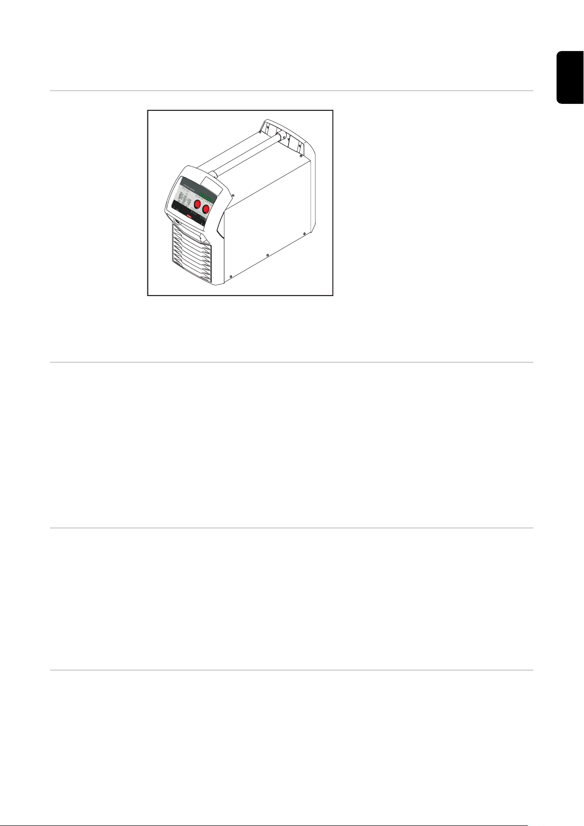
Connections, switches and mechanical compon-
(1)
(2)
(3)
(4)
(6)
(7)
(9)
(8)
(5)
ents
TSt 3500/5000
Syn power
source
(1) (-) - current socket with bayonet latch
Used for
Connecting the grounding cable during MIG/MAG welding
-
Connecting the electrode cable or grounding cable during manual
-
metal arc welding (depending on the type of electrode used)
EN
(2) Mains switch
For switching the power source on and off
(3) (+) - current socket with bayonet latch
Used for
Connecting the current cable from the interconnecting hosepack dur-
-
ing MIG/MAG welding
Connecting the electrode cable or grounding cable during manual
-
metal arc welding (depending on the type of electrode used)
(4) Gas preheater socket (option)
(5) Machine interface (optional)
(6) EASY DOCUMENTATION sticker
(7) Mains cable with strain relief device
(8) LocalNet port
Standardised connection socket for the wirefeeder (interconnecting
hosepack)
(9) Air filter
Remove from the side for cleaning
37

38

Installation and commissioning
39

40

Minimum equipment needed for welding task
General Depending on which welding process you intend to use, a certain minimum equip-
ment level will be needed in order to work with the power source.
The welding processes and the minimum equipment levels required for the welding task are then described.
EN
Gas-cooled
MIG/MAG welding
MIG/MAG welding, watercooled
MMA welding
Power source
-
Grounding cable
-
MIG/MAG welding torch, gas-cooled
-
Gas connection (shielding gas supply)
-
Wirefeeder (VR 5000 Remote)
-
Interconnecting hosepack, gas-cooled
-
Wire electrode
-
Power source
-
Cooling unit
-
Grounding cable
-
MIG/MAG welding torch, water-cooled
-
Gas connection (shielding gas supply)
-
Wirefeeder (VR 5000 Remote)
-
Water-cooling option (for VR 5000 Remote)
-
Interconnecting hosepack, water-cooled
-
Wire electrode
-
Power source
-
Grounding cable
-
Electrode holder
-
Rod electrodes
-
41

Before installation and commissioning
Safety
WARNING!
Danger from incorrect operation and work that is not carried out properly.
This can result in serious personal injury and damage to property.
All the work and functions described in this document must only be carried
▶
out by technically trained and qualified personnel.
Read and understand this document in full.
▶
Read and understand all safety rules and user documentation for this device
▶
and all system components.
WARNING!
Danger from electrical current.
This can result in serious personal injury and damage to property.
Before starting work, switch off all devices and components involved and dis-
▶
connect them from the grid.
Secure all devices and components involved so they cannot be switched back
▶
on.
After opening the device, use a suitable measuring instrument to check that
▶
electrically charged components (such as capacitors) have been discharged.
Utilisation for intended purpose
only
Setup regulations
The power source may only be used for MIG/MAG and MMA welding.
Any other form of usage is deemed "not in accordance with the intended purpose".
The manufacturer shall not be held liable for any damages arising from such usage.
Utilisation in accordance with the "intended purpose" also comprises
following all the information in the operating instructions
-
carrying out all the specified inspection and servicing work
-
The device is tested to IP 23 protection, meaning:
Protection against penetration by solid foreign bodies with diameters > 12
-
mm (0.49 in.)
Protection against spraywater at any angle up to 60° to the vertical
-
The device can be set up and operated outdoors in accordance with degree of
protection IP 23.
Avoid direct wetting (e.g. from rain).
WARNING!
Danger from machines toppling over or falling.
This can result in serious personal injury and damage to property.
Set up the device securely on an even, solid surface.
▶
Check all screw connections are tightly fastened after installation.
▶
42

WARNING!
Mains connection
Danger from electrical current due to electrically conductive dust in the device.
This can result in serious injury and damage to property.
Only operate the device with an air filter fitted. The air filter is a very import-
▶
ant safety device for achieving IP 23 protection.
The venting duct is a very important safety device. When choosing the installation location, ensure that the cooling air can enter and exit unhindered through
the air ducts on the front and back of the device. Electroconductive metallic
dust (e.g. from grinding work) must not be allowed to get sucked into the device.
The devices are designed for the mains voltage specified on the rating plate. If
your version of the appliance does not come with mains cables and plugs readyfitted, these must be fitted in accordance with national regulations and standards. For details of fuse protection of the mains lead, please see the technical
data.
CAUTION!
Danger due to insufficiently dimensioned electrical installations.
This can result in damage to property.
Dimension the mains lead and its fuse to suit the local power supply.
▶
The technical data shown on the rating plate applies.
EN
43

Connecting the mains cable
Safety
Danger due to work that has been carried out incorrectly.
This can result in serious injury and damage to property.
▶
▶
Danger due to improperly prepared mains cable.
This can cause short circuits and damage.
▶
General If no mains cable is connected, a mains cable that is suitable for the connection
voltage must be fitted before commissioning.
A strain-relief device for the following cable cross-sections is fitted to the power
source:
WARNING!
The work described below must only be carried out by trained and qualified
personnel.
Observe national standards and directives.
CAUTION!
Fit ferrules to all phase conductors and the ground conductor of the
stripped mains cable.
Stipulated mains
cables and
strain-relief
devices
Power source Cable cross-section
fitted strain-relief device
for
Canada / US
TSt 3500 Syn AWG 12 *) 4G2.5
TSt 5000 Syn AWG 10 *) 4G4
TSt 3500 MV Syn AWG 10 *) 4G4
TSt 5000 MV Syn AWG 6 *) 4G10
*) Canada / US cable type: Extra-hard usage
Strain-relief devices for other cable cross-sections must be designed accordingly.
Power source Mains voltage Cable cross-sec-
tion
Canada / US
TSt 3500 Syn 3 x 380 / 400 V AWG 12 *) 4G2.5
3 x 460 V AWG 12 *) 4G2.5
Europe
Europe
44
TSt 5000 Syn 3 x 380 / 400 V AWG 8 *) 4G4
3 x 460 V AWG 10 *) 4G4
TSt 3500 MV
Syn
3 x 208 / 230 / 400 / 460VAWG 10 *) 4G4

TSt 5000 MV
3
1
2
5
4
7
3
4
100mm
(4inch)
PE
2
3 x 208 / 230 / 400 / 460VAWG 6 *) 4G10
Syn
*) Canada / US cable type: Extra-hard usage
The item numbers of the different cables can be found in the Spare Parts List of
the device.
AWG ... American Wire Gauge
EN
Connecting the
mains cable
Fitting the
Europe strainrelief device
If no mains cable is connected, a mains cable that is suitable for the connection
voltage must be fitted before commissioning.
The ground conductor should be approx. 10 - 15 mm (0.4 - 0.6 in.) longer than
the phase conductors.
An illustration of the mains cable connection can be found in the following sections: "Fitting the strain-relief device" or "Fitting the strain-relief device for
Canada / US". To connect the mains cable, proceed as follows:
Remove the side panel from the device
1
Push the mains cable in far enough to make it possible to connect the ground
2
conductor and the phase conductors to the block terminal properly.
Fit ferrules to the ground conductor and phase conductors
3
Connect the ground conductor and phase conductors to the block terminal
4
Use the strain-relief device to secure the mains cable
5
Fit the side panel of the device
6
1
2
45

3
1
3
3
3
3
3
4
4x
3
1,2 Nm
1
4
3
2
5
6
3
1
2
5
4
7
4
Fitting the
Canada/US
strain-relief
device
5
IMPORTANT! Tie the phase conduct-
ors near the block terminals using
cable ties.
1 2
46

3
1
3
3
3
3
3
4
4x
3
3,5 Nm
1
4
3
2
5
6
4
EN
5
IMPORTANT! Tie the phase conduct-
ors near the block terminals using
cable ties.
47

Generator-powered operation
Generatorpowered operation
The power source is generator-compatible.
The maximum apparent power S
of the power source must be known in order
1max
to select the correct generator output.
The maximum apparent power S
3-phase devices: S
Single-phase devices: S
1max
= I
1max
1max
= I
x U1 x √3
See device rating plate or technical data for I
The generator apparent power S
of the power source is calculated as follows:
1max
x U
1max
GEN
1
and U1 values
1max
needed is calculated using the following rule
of thumb:
S
GEN
= S
1max
x 1.35
A smaller generator may be used when not welding at full power.
IMPORTANT! The generator apparent power S
the maximum apparent power S
of the power source.
1max
must always be higher than
GEN
When using single-phase devices with a 3-phase generator, note that the specified generator apparent power is often only available as a whole across all three
phases of the generator. If necessary, obtain further information on the singlephase power of the generator from the generator manufacturer.
NOTE!
The voltage delivered by the generator must never exceed the upper or lower
limits of the mains voltage tolerance range.
Details of the mains voltage tolerance can be found in the "Technical data" section.
48

Start-up
General Commissioning a power source is described by reference to a manual water-
cooled MIG/MAG application.
EN
Information on
system components
Assembling the
system components (overview)
The steps and activities described below include references to various system
components, including:
trolley
-
upright console
-
cooling units
-
wire-feed units
-
interconnecting hosepacks
-
welding torches, etc.
-
For more detailed information about installing and connecting the system components, please refer to the appropriate operating instructions.
WARNING!
Work that is carried out incorrectly can cause serious injury and damage.
The following activities must only be carried out by trained and qualified per-
▶
sonnel.
All instructions in the section headed "Safety rules" must be observed.
▶
The diagram below is intended to show you how to fit the individual system components.
49

Placing the
1
wirefeeder on
the power source
CAUTION!
Risk of injury and material damage from falling wirefeeder.
Make sure that the wirefeeeder is located securely on the swivel pin and that
▶
the devices, upright consoles and trolleys are stable.
1
50

Fitting the inter-
1
2
3
4
2
1
3
4
1
2
7
4
5
6
3
connecting
hosepack strainrelief device
1
2
EN
Connecting the
interconnecting
hosepack
Fitting the strain-relief device to the trolley
Fitting the strain-relief device to the wirefeeder
IMPORTANT! To prevent wear and tear, leave some slack when connecting the
cables. A strain-relief device is not provided for 1.2 m (3 ft 11.24 in.) interconnecting hosepacks.
WARNING!
Fitting the equipment incorrectly can cause serious injury and damage.
Do not carry out the steps described here until you have read and completely
▶
understood all the Operating Instructions.
NOTE!
When connecting the interconnecting hosepack, check that
all connections are connected properly
▶
all cables, leads and hosepacks are undamaged and correctly insulated
▶
IMPORTANT! There is no cooling unit present in the case of gas-cooled systems.
There is no need to attach the water connections in the case of gas-cooled systems.
1
2
51

Connecting the
gas cylinder
WARNING!
There is a high risk of very serious injury and damage if a gas cylinder falls over.
When using gas cylinders:
Place them on a solid, level surface in such a way that they remain stable
▶
Secure the gas cylinders to prevent them from falling over
▶
Fit the VR holder option
▶
Observe the safety rules of the gas cylinder manufacturer
▶
Place the gas cylinder on the base
1
of the trolley
Secure the gas cylinder by fixing
2
the cylinder strap around the upper part of the cylinder (but not
around the neck) to prevent it from
toppling over
Take the protective cap off the gas
3
cylinder
Briefly open the gas cylinder valve
4
to remove any dust or dirt
Inspect the seal on the gas pres-
5
sure regulator
Screw the pressure regulator onto
6
the gas cylinder and tighten it
Connect the shielding gas hose of
7
the interconnecting hosepack to
the pressure regulator using the
gas hose
NOTE!
US devices are supplied with an adapter for the gas hose:
Seal male thread spacers on the gas solenoid valve using suitable means be-
▶
fore screwing on the adapter.
Test the adapter to ensure that it is gas-tight.
▶
52

Establishing a
1
3
2
ground earth
connection
NOTE!
When establishing a ground earth connection, observe the following points:
Use a separate grounding cable for each power source
▶
Keep the plus cable and grounding cable together as long and as close as
▶
possible
Physically separate the welding circuits of individual power sources
▶
Do not route several grounding cables in parallel;
▶
if parallel routing cannot be avoided, keep a minimum distance of 30 cm
between the welding circuits
Keep the grounding cable as short as possible, provide a large cable cross-
▶
section
Do not cross grounding cables
▶
Avoid ferromagnetic materials between the grounding cable and the inter-
▶
connecting hosepack
Do not wind up long grounding cables - coil effect!
▶
Lay long grounding cables in loops
Do not route grounding cables in iron pipes, metal cable conduits or on steel
▶
rails, avoid cable ducts;
(routing of plus cables and grounding cables together in an iron pipe does
not cause any problems)
If there are several grounding cables, separating the grounding points on the
▶
component so that they are as far away from one another as possible is recommended, as well as preventing crossed current paths from occurring underneath the individual arcs.
Use compensated interconnecting hosepacks (interconnecting hosepacks
▶
with integrated grounding cable)
EN
1
53

Connecting
2
1
4
4
5
6
3
6
3
31
2
4
5
7
MIG/MAG welding torches
1
* when the optional water connection
and the water-cooled welding torch are
fitted
Inserting/replacing feed rollers
CAUTION!
Danger from feed roller holders flying upwards.
This can result in injuries.
When unlocking the clamping lever, keep fingers away from the area to the
▶
left and right of the lever.
1
2
CAUTION!
Danger from exposed feed rollers.
This can result in injuries.
Always fit the protective cover of the 4-roller drive after inserting or repla-
▶
cing a feed roller.
54

3
8
6
7
9
3
1
2
2
5
4
4
3
4
5
5
6
1
2
3
4
EN
Inserting the
wirespool
CAUTION!
Risk of injury due to springiness of spooled wire electrode.
While inserting the wirespool, hold the end of the wire electrode firmly to
▶
avoid injuries caused by the wire springing back.
CAUTION!
Risk of injury from falling wirespool.
Make sure the wirespool sits securely on the wirespool holder.
▶
CAUTION!
Risk of injury and material damage if the wirespool topples over because the
locking ring has been placed the wrong way around.
Always position the locking ring as shown in the diagram on the left.
▶
55

1
Inserting the
basket-type
spool
CAUTION!
Risk of injury due to springiness of spooled wire electrode.
When inserting the basket-type spool, hold the end of the wire electrode
▶
firmly to avoid injuries caused by the wire springing back.
CAUTION!
Risk of injury from falling basket-type spool.
Make sure that the basket-type spool and basket-type spool adapter are fit-
▶
ted securely to the wirespool holder.
NOTE!
When working with basket-type spools, only use the basket-type spool adapter
included in the scope of supply.
CAUTION!
Risk of injury and material damage if the basket-type spool topples over because the locking ring has been placed the wrong way round.
Always position the locking ring as shown in the diagram on the left.
▶
56

CAUTION!
Feeding in the
wire electrode
Risk of injury and material damage from falling basket-type spool.
Place the basket-type spool on the adapter provided in such a way that the
▶
bars on the spool are inside the adapter guideways.
1 2
CAUTION!
Risk of injury due to springiness of spooled wire electrode.
When inserting the wire electrode into the 4-roller drive, hold the end of the
▶
wire electrode firmly to avoid injuries caused by the wire springing back.
EN
CAUTION!
Risk of damage to the welding torch from sharp end of wire electrode.
Deburr the end of the wire electrode well before threading in.
▶
1 2
57

CAUTION!
Fdi
1
2 3
4
5
2,5
1
t (s)
(m/min, ipm)
Risk of injury from emerging wire electrode.
When pressing the wire threading button or the torch trigger, keep the weld-
▶
ing torch away from your face and body, and wear suitable protective
goggles.
IMPORTANT! To facilitate the exact positioning of the wire electrode, the following sequences are possible when the wire threading button is pressed and held
down.
Hold the button for up to one
-
second ... the wire speed stays at 1
m/min or 39.37 ipm for the first
second.
Hold the button for up to 2.5
-
seconds ... after one second has
elapsed, the wire speed increases
at a uniform rate over the next 1.5
seconds.
Hold the button for more than 2.5
-
seconds ... after 2.5 seconds, the
wire is fed at a constant rate equal
to the wire speed set for the Fdi
welding parameter.
If the "Wire threading" button is released and pressed again before one second
has elapsed, the sequence starts again from the beginning. This makes it possible
to continuously position the wire at a low wire speed of 1 m/min or 39.37 ipm
where necessary.
If there is no "Wire threading" button, the torch trigger can be used in the same
way. Before using the torch trigger for wire threading, proceed as follows:
Press the "Mode" button to select 2-step mode
1
Set the "Ito" parameter to "Off" in the Setup menu
2
CAUTION!
Risk of injury and damage from electric shock and from the wire electrode
emerging from the torch.
When pressing the torch trigger:
Keep the welding torch away from your face and body
▶
Wear suitable protective goggles
▶
Do not point the welding torch at people
▶
Make sure that the wire electrode does not touch any conductive or earthed
▶
parts (e.g. housing)
IMPORTANT! If the torch trigger is pressed instead of the "Wire threading" button, the welding wire runs at the feeder creep speed (depending on the welding
program) for the first 3 seconds. After these 3 seconds, wirefeeding is briefly interrupted.
The welding system detects that the welding process should not start, but that
the wire is to be fed in. At the same time, the gas solenoid valve closes, and the
welding voltage on the wire electrode is switched off.
58

If the torch trigger is held down, wirefeeding restarts immediately without shield-
2
4
5
3
1
1
ing gas and welding voltage, and the process continues as described above.
3 4
EN
Setting the contact pressure
CAUTION!
Risk from excessive contact pressure.
This can result in severe damage to property and poor weld properties.
Set the contact pressure in such a way that the wire electrode is not de-
▶
formed but nevertheless ensures proper wirefeeding.
1
Contact pressure preferred values for
U-groove rollers:
Steel: 4 - 5
CrNi: 4 - 5
Tubular cored electrodes: 2 - 3
Adjusting the
brake
NOTE!
After releasing the "Wire threading" button, the wirespool should stop unreeling.
If it continues unreeling, readjust the brake.
▶
59

4
6
7
1
2
STOP
3
5
1
2
1
2
4
STOP
OK
1
3
3
2
Design of the
brake
60
WARNING!
Danger from incorrect installation.
This can result in severe personal injury and damage to property.
Do not dismantle the brake.
▶
Maintenance and servicing of
▶
brakes is to be carried out by
trained, qualified personnel only.
The brake is only available as a complete unit.
This illustration of the brake is for information purposes only.

Welding
61

62

Power limitation
Safety function "Power limitation" is a safety function for MIG/MAG welding. This means that the
power source can be operated at the power limit whilst maintaining process
safety.
Wire speed is a determining parameter for welding power. If it is too high, the arc
gets smaller and smaller and may be extinguished. In order to prevent this, the
welding power is lowered.
For the selected "MIG/MAG standard synergic welding" process, the symbol for
the "Wire speed" parameter flashes as soon as the safety function trips. The
flashing continues until the next welding start-up, or until the next parameter
change.
For example, if the "Wire speed" parameter is selected, the reduced value for
wire speed is displayed.
EN
63

MIG/MAG modes
General
Symbols and
their explanations
WARNING!
Operating the equipment incorrectly can cause serious injury and damage.
Do not use the functions described here until you have read and completely
▶
understood these Operating Instructions.
Do not use the functions described here until you have fully read and under-
▶
stood all of the Operating Instructions for the system components, in particular the safety rules.
For details of the meaning, settings, setting range and units of the available
welding parameters (e.g. gas pre-flow time), please refer to the "Setup parameters" chapter.
Press the torch trigger | Hold the torch trigger | Release the torch trigger
GPr Gas pre-flow time
I-S Starting current
Can be increased or decreased depending on the application
SL Slope
The starting current is continuously lowered as far as the welding current
and the welding current as far as the final current
I Welding current phase
Uniform thermal input into the base material, whose temperature is raised
by the advancing heat
I-E Final current
To fill the end-crater
GPo Gas post-flow time
SPt Spot welding time / interval welding time
SPb Interval pause time
64

2-step mode
t
I
+
I
GPr
GPo
t
I
+
I
GPr GPo
+
"2-step mode" is suitable for
Tacking work
-
Short weld seams
-
Automated and robot welding
-
EN
4-step mode
"4-step mode" is suitable for longer weld seams.
65

Special 4-step
+ +
I
I-S I-E
GPr SL SL
GPo
I
+
I
GPr GPoSPt
t
< SPt
mode
Spot welding
Special 4-step mode allows the starting and final current to be configured in addition to the advantages of 4-step mode.
The "Spot welding" mode is suitable for welded joints on overlapped sheets.
Start by pressing and releasing the torch trigger - GPr gas pre-flow time - Welding current phase for the duration of the SPt spot welding time - GPo gas post-
flow.
If the torch trigger is pressed again before the end of the spot welding time (<
SPt), the process is cancelled immediately.
66

2-step stitch
GPr SPt SPtSPb
GPo
I I
+
I
I
GPr SPt SPtSPb
GPo
+
+
welding
4-step stitch
welding
EN
2-step stitch welding
The "2-step stitch welding" mode is suitable for welding short weld seams on thin
sheets, to prevent the weld seams from dropping through the base material.
4-step stitch welding
The "4-step stitch welding" mode is suitable for welding longer weld seams on
thin sheets, to prevent the weld seams from dropping through the base material.
67

MIG/MAG welding
Safety
WARNING!
Danger from incorrect operation and work that is not carried out properly.
This can result in serious personal injury and damage to property.
All the work and functions described in this document must only be carried
▶
out by technically trained and qualified personnel.
Read and understand this document in full.
▶
Read and understand all safety rules and user documentation for this device
▶
and all system components.
WARNING!
Danger from electrical current.
This can result in serious personal injury and damage to property.
Before starting work, switch off all devices and components involved and dis-
▶
connect them from the grid.
Secure all devices and components involved so they cannot be switched back
▶
on.
After opening the device, use a suitable measuring instrument to check that
▶
electrically charged components (such as capacitors) have been discharged.
Preparatory
work
Overview MIG/MAG welding is composed of the following sections:
Connect welding torch water hoses to the correct connections on the
1
wirefeeder
(when using a cooling unit and water-cooled welding torch)
Plug in the mains plug
2
Move the mains switch to the "I" position:
3
all the indicators on the control panel light up briefly
-
where applicable, the cooling unit starts to run
-
IMPORTANT! Follow the safety rules and note operating conditions in the cooling unit Operating Instructions.
MIG/MAG standard synergic welding
-
MIG/MAG standard manual welding
-
Spot and stitch welding
-
68

MIG/MAG standard synergic welding
EN
MIG/MAG
standard synergic welding
Press the "Material" button to select the filler metal to be used.
1
Press the "Wire diameter" button to select the diameter of the wire elec-
2
trode used.
Press the "Shielding gas" button to select the shielding gas to be used.
3
The assignment of the SP position is in the welding program tables in the
appendix.
Press the "Process" button to select the desired welding process:
4
MIG/MAG standard synergic welding
-
Press the "Mode" button to select the desired MIG/MAG mode:
5
2-step mode
-
4-step mode
-
Special 4-step mode
-
IMPORTANT! Under certain circumstances, it may not be possible to
change welding parameters that have been set on the control panel of a
system component (TR 2000 or TR 3000 remote control) on the control
panel of the power source.
Use the "Parameter selection" buttons to select the welding parameters to
6
be used to specify the welding power:
7
Sheet thickness
-
Welding current
-
Wire speed
-
Welding voltage
-
Use the appropriate adjusting dial to set the relevant welding parameters.
The welding parameter values are shown in the digital display located
above them.
All welding parameter set values remain stored until the next time they are
changed. This applies even if the power source is switched off and on again.
To display the actual welding current during welding, select the welding
current parameter.
Open the gas cylinder valve
8
Setting the shielding gas flow rate:
9
Tap the "Gas-test" button
-
Turn the adjusting screw on the underside of the pressure regulator
-
until the pressure gauge shows the required gas flow rate
Tap the "Gas-test" button again
-
69

CAUTION!
Risk of injury and damage from electric shock and from the wire electrode
emerging from the torch.
When pressing the torch trigger
keep the welding torch away from your face and body
▶
wear suitable protective goggles
▶
do not point the welding torch at people
▶
make sure that the wire electrode does not touch any conductive or earthed
▶
parts (e.g. housing)
Press the torch trigger and start welding
10
Corrections during welding
The arc length correction and arc-force dynamic parameters can be used to optimise the welding result.
Arc length correction:
- = shorter arc, reduced welding voltage
0 = neutral arc
+ = longer arc, increased welding voltage
Arc-force dynamic:
To influence the short-circuiting dynamic at the instant of droplet transfer
- = hard, stable arc
0 = neutral arc
+ = soft, low-spatter arc
70

MIG/MAG standard manual welding
General The MIG/MAG standard manual welding process is a MIG/MAG welding process
with no synergic function.
Changing one parameter does not result in any automatic adjustments to the
other parameters. All of the variable parameters must therefore be adjusted individually, as dictated by the welding process in question.
EN
Available parameters
MIG/MAG
standard manual
welding
The following parameters are available in MIG/MAG manual welding:
Wire feed speed
1 m/min (39.37 ipm) - maximum wire feed speed, e.g. 25 m/min (984.25
ipm)
Welding voltage
TSt 3500: 15.5 - 31.5 V
TSt 5000: 14.5 - 39 V
Dynamic
for influencing the short-circuiting dynamic at the moment of particle
transfer
Welding current
only for displaying the actual value
Press the "Process" button to select the desired welding process:
1
MIG/MAG standard manual welding
-
Press the "Mode" button to select the desired MIG/MAG mode:
2
2-step mode
-
4-step mode
-
In MIG/MAG standard manual welding, special 4-step mode corres-
-
ponds to conventional 4-step mode.
IMPORTANT! Under certain circumstances, it may not be possible to
change welding parameters that have been set on the control panel of a
system component (TR 2000 or TR 3000 remote control) on the control
panel of the wirefeeder.
Press the "Parameter selection" button to select the wire speed parameter
3
Use the adjusting dial to set the desired value for the wire speed
4
Press the "Parameter selection" button to select the welding voltage para-
5
meter
Use the adjusting dial to set the desired value for the welding voltage
6
The welding parameter values are shown in the digital display located
above them.
71

All welding parameter set values remain stored until the next time they are
changed. This applies even if the power source is switched off and on again.
To display the actual welding current during welding, select the welding
current parameter.
To display the actual welding current during welding:
Press the "Parameter selection" button to select the welding current
-
parameter
The actual welding current is shown on the digital display during weld-
-
ing.
Open the gas cylinder valve
7
Setting the shielding gas flow rate:
8
Tap the "Gas-test" button
-
Turn the adjusting screw on the underside of the pressure regulator
-
until the pressure gauge shows the required gas flow rate
Tap the "Gas-test" button again
-
CAUTION!
Risk of injury and damage from electric shock and from the wire electrode
emerging from the torch.
When pressing the torch trigger
keep the welding torch away from your face and body
▶
wear suitable protective goggles
▶
do not point the welding torch at people
▶
make sure that the wire electrode does not touch any conductive or earthed
▶
parts (e.g. housing)
Corrections during welding
Press the torch trigger and start welding
9
To obtain the best possible welding results, the arc-force dynamic parameter will
sometimes need to be adjusted.
Press the "Parameter selection" button to select the arc-force dynamic para-
1
meter
Use the adjusting dial to set the desired arc-force dynamic value
2
The welding parameter value is shown in the digital display located above it.
72

Spot and stitch welding
General The spot and stitch welding modes are MIG/MAG welding processes. The spot
and stitch welding modes can be activated on the power source control panel.
Spot welding is used on welded joints on overlapped sheets that are only accessible on one side.
Stitch welding is used for light-gauge sheets.
As the wire electrode is not fed continuously, the weld pool can cool down during
the intervals. Local overheating leading to the base material being melted
through is largely avoided.
Spot welding Activating spot welding mode:
For the SPt Setup parameter (spot / stitch welding time), enter a value >
-
OFF
As soon as a value is entered for the SPt Setup parameter, spot welding mode is
activated. The spot / stitch welding indicator (SF) lights up on the control panel.
EN
Preparations:
Set the spot / stitch welding time (SPt) in the Setup menu
1
Select the filler metal, wire diameter and shielding gas being used with the
2
relevant buttons
Select the desired welding process:
3
MIG/MAG standard manual welding
MIG/MAG standard synergic welding
Select the desired MIG/MAG mode:
4
2-step mode
(For spot welding mode, only 2-step mode is available)
Depending on the selected welding process, select the desired welding para-
5
meters using the relevant adjusting dial
Open the gas cylinder valve
6
Set the shielding gas flow rate
7
WARNING!
Danger due to emerging wire electrode.
This can result in serious personal injuries.
Hold the welding torch so that the tip of the welding torch points away from
▶
the face and body.
Wear suitable protective goggles.
▶
Do not point the welding torch at people.
▶
Ensure that the wire electrode does not touch any electrically conductive ob-
▶
jects.
73

Spot welding
12
Procedure for producing a welding spot:
Hold the welding torch vertical
1
Press and release the torch trigger
2
Keep the welding torch in the same position
3
Wait for the gas post-flow time
4
Raise the welding torch
5
Stitch welding Activating stitch welding mode:
For the SPt Setup parameter (spot / stitch welding time), enter a value >
-
OFF
For the SPt Setup parameter (spot pause time), enter a value > OFF
-
As soon as a value is entered for the SPt Setup parameter, the spot / stitch welding indicator (SF) lights up.
Preparations:
Set the spot / stitch welding time (SPt) in the Setup menu
1
Set the spot pause time (SPb) in the Setup menu
2
Select the filler metal, wire diameter and shielding gas being used with the
3
relevant buttons
Select the desired welding process:
4
MIG/MAG standard manual welding
MIG/MAG standard synergic welding
Select the desired MIG/MAG mode for stitch welding mode:
5
2-step mode
4-step mode
Depending on the selected welding process, select the desired welding para-
6
meters using the relevant adjusting dial
Open the gas cylinder valve
7
Set the shielding gas flow rate
8
CAUTION!
Risk of injury and damage from electric shock and from the wire electrode
emerging from the torch.
When pressing the torch trigger
keep the welding torch away from your face and body
▶
wear suitable protective goggles
▶
do not point the welding torch at people
▶
make sure that the wire electrode does not touch any conductive or earthed
▶
parts (e.g. housing)
74
Stitch welding
10

Procedure for stitch welding:
Hold the welding torch vertical
1
Depending on the selected mode:
2
press and hold the torch trigger (2-step mode)
press and release the torch trigger (4-step mode)
Keep the torch in the same position
3
Wait for the welding interval
4
Position the welding torch at the next point
5
To end stitch welding, depending on the selected mode:
6
release the torch trigger (2-step mode)
press and release the torch trigger (4-step mode)
Wait for the gas post-flow time
7
Lift the torch off the workpiece
8
EN
75

EasyJob mode
General The "Save" buttons allow up to 5 EasyJob operating points to be saved. Every op-
erating point matches the settings on the control panel.
EasyJobs can be stored for each welding process.
IMPORTANT! Setup parameters are not saved at this time.
Storing EasyJob
operating points
Retrieving EasyJob operating
points
Deleting EasyJob operating
points
Press and hold one of the "Save" buttons to save the current set-
1
tings on the control panel, e.g.:
The left indicator displays "Pro"
-
After a short time, the left indicator switches to the original
-
value
Release the "Save" button
2
To retrieve saved settings, press the corresponding "Save" button
1
briefly, e.g.:
The control panel will show the saved settings
-
Press and hold the relevant "Save" button to delete the memory
1
content of that "Save" button, e.g.:
The left indicator displays "Pro".
-
After a short time, the left indicator switches to the original
-
value
Keep the "Save" button held down
2
The left display shows "CLr".
-
After a while, both displays show "---"
-
Retrieving EasyJob operating
points on the Up/
Down welding
torch
76
Release the "Save" button
3
One of the "Save" buttons on the control panel must be pressed in order to retrieve the saved settings using the Up/Down welding torch.
Press one of the "Save" buttons on the control panel, e.g.:
1
The control panel will show the saved settings.
The "Save" buttons can now be selected using the buttons on the Up/Down welding torch. Vacant "Save" buttons are skipped.

In addition to the "Save" button number lighting up, a number is displayed directly on the Up/Down welding torch:
Indicator on the Up/Down welding
torch
EasyJob operating point on the con-
trol panel
EN
77

MMA welding
Safety
WARNING!
Danger from incorrect operation and work that is not carried out properly.
This can result in serious personal injury and damage to property.
All the work and functions described in this document must only be carried
▶
out by technically trained and qualified personnel.
Read and understand this document in full.
▶
Read and understand all safety rules and user documentation for this device
▶
and all system components.
WARNING!
Danger from electrical current.
This can result in serious personal injury and damage to property.
Before starting work, switch off all devices and components involved and dis-
▶
connect them from the grid.
Secure all devices and components involved so they cannot be switched back
▶
on.
After opening the device, use a suitable measuring instrument to check that
▶
electrically charged components (such as capacitors) have been discharged.
Preparation
MMA welding
Move the mains switch to the "O" position
1
Disconnect the mains plug
2
Detach all cables to the wirefeeder at the power source
3
IMPORTANT! Check the rod electrode packaging to determine whether the
rod electrodes are for (+) or (-) welding.
Plug the grounding cable into either the (-) or the (+) current socket, depend-
4
ing on the type of electrode, and lock in place
Use the other end of the grounding cable to establish a connection to the
5
workpiece
Plug the bayonet current plug of the electrode holder cable into the free cur-
6
rent socket with the opposite polarity, according to the type of electrode, and
twist it clockwise to latch it in place
Plug in the mains plug
7
CAUTION!
Risk of injury and damage from electric shock.
As soon as the mains switch is in the "I" position, the rod electrode in the electrode holder is live.
Make sure that the rod electrode does not touch any persons or electrically
▶
conductive or earthed parts (e.g. the housing, etc.)
78

Move the mains switch to the "I" position: all the indicators on the control
1
panel will briefly light up
Press the "Process" button to select the MMA welding process:
2
The welding voltage is applied to the welding socket with a three second time
lag.
If the MMA welding process is selected, any cooling unit present is automatically deactivated. It is not possible to switch it on.
NOTE!
Under certain circumstances, it may not be possible to change welding
parameters that have been set on a system component (such as remote control or wirefeeder) from the control panel of the power source.
Press the "Parameter selection" button to select the amperage parameter.
3
Use the adjusting dial to set the desired amperage.
4
The amperage value is displayed in the left-hand digital display.
EN
Corrections during welding
All welding parameter set values that have been set using the adjusting dial
remain stored until the next time they are changed. This applies even if the
power source was switched off and on again in the interim.
Start welding
5
To display the actual welding current during welding:
Press the "Parameter selection" button to select the welding current para-
-
meter
The actual welding current is shown on the digital display during welding.
-
To obtain the best possible welding results, the arc-force dynamic parameter will
sometimes need to be adjusted.
Press the "Parameter selection" button to select the arc-force dynamic para-
1
meter
Use the adjusting dial to set the desired arc-force dynamic value
2
The welding parameter value is shown in the digital display located above it.
Influence of the short-circuiting dynamic at the instant of droplet transfer:
- = hard, stable arc
0 = neutral arc
+ = soft, low-spatter arc
79

HotStart func-
I (A)
300
200
HCU
I
H
HCU > I
H
t (s)
0,5
1
1,5
Hti
tion
To obtain optimum welding results, it will sometimes be necessary to adjust the
HotStart function.
Advantages
Improved ignition properties, even when using electrodes with poor ignition
-
properties
Better fusion of the base material during the start-up phase, meaning fewer
-
cold-shut defects
Largely prevents slag inclusions
-
For details on setting the available welding parameters, please refer to "Setup
parameters", "Setup menu - level 2".
Legend
Hti Hot-current time,
0 - 2 s,
factory setting: 0.5 s
HCU HotStart current,
100 - 200 %,
factory setting 150 %
Anti-stick function
I
Main current = set welding cur-
H
rent
Function
During the specified hot-current time
(Hti), the welding current is increased
to a certain value. This value (HCU) is
higher than the selected welding current (IH).
As the arc becomes shorter, the welding voltage may drop so far that the rod
electrode will tend to stick. This may also cause the rod electrode to burn out.
Electrode burn-out is prevented by activating the anti-stick function. If the rod
electrode begins to stick, the power source immediately switches the welding
current off. After the rod electrode has been detached from the workpiece, the
welding process can be continued without any problems.
The anti-stick function (Ast) can be activated and deactivated in the Setup menu
with the Setup parameters for manual metal arc welding.
80

Arc Air Gauging (TSt 5000 Syn)
EN
Safety
WARNING!
Danger from incorrect operation and work that is not carried out properly.
This can result in serious personal injury and damage to property.
All the work and functions described in this document must only be carried
▶
out by technically trained and qualified personnel.
Read and understand this document in full.
▶
Read and understand all safety rules and user documentation for this device
▶
and all system components.
WARNING!
Danger from electrical current.
This can result in serious personal injury and damage to property.
Before starting work, switch off all devices and components involved and dis-
▶
connect them from the grid.
Secure all devices and components involved so they cannot be switched back
▶
on.
After opening the device, use a suitable measuring instrument to check that
▶
electrically charged components (such as capacitors) have been discharged.
Preparation IMPORTANT! A grounding cable with a cable cross-section of 120 mm² is re-
quired for arc air gouging.
Move the mains switch to the "O" position
1
Disconnect the mains plug
2
Remove the MIG/MAG welding torch
3
Plug the grounding cable into the (-) current socket and twist to fasten it
4
Use the other end of the grounding cable to establish a connection to the
5
workpiece
Plug the bayonet current plug of the arc air gouging torch into the (+) current
6
socket and twist it clockwise to fasten it
Connect the compressed air connection of the arc air gouging torch to the
7
compressed air supply
Working pressure: 5 - 7 bar (constant)
Clamp the carbon electrode so that the electrode tip protrudes approxim-
8
ately 100 mm out of the arc air gouging torch;
the air outlet openings of the arc air gouging torch must be located at the
bottom
Plug in the mains plug
9
81

Arc air gouging
CAUTION!
Risk of injury and damage from electric shock.
As soon as the mains switch is in the "I" position, the electrode in the arc air gouging torch is live.
Make sure the electrode does not touch any persons or electrically conduct-
▶
ing or earthed parts (e.g. the housing, etc.).
CAUTION!
Risk of personal injury due to loud operating noise.
Use suitable ear protection during arc air gouging!
▶
Move the mains switch to the "I" position: all the indicators on the control
1
panel will briefly light up
Press the "Process" button to select the MMA welding process:
2
The welding voltage is applied to the welding socket with a three second time
lag.
If the MMA welding process is selected, any cooling unit present is automatically deactivated. It is not possible to switch it on.
IMPORTANT! Under certain circumstances, it may not be possible to change
welding parameters that have been set on a control panel of a system component
(such as remote control or wirefeeder) from the control panel of the power
source.
In the setup menu for MMA welding, set the AAG parameter to "on";
3
To enter the setup menu, see page 93.
NOTE!
Settings for the break voltage and the starting current time are ignored.
Exit the setup menu for MMA welding
4
Press the "Parameter selection" button to select the amperage parameter.
5
Using the adjusting dial, adjust the main current according to the electrode
6
diameter as indicated on the electrode packaging
The amperage value is displayed in the left-hand digital display.
NOTE!
82
At higher amperages, guide the arc air gouging torch with both hands!
Use a suitable welding helmet.
▶
Open the compressed air valve on the handle of the arc air gouging torch
7
Initiate processing
8
The tilt angle of the carbon electrode and the gouging speed determine the
depth of an air gap.

The arc air gouging parameters are the same as the welding parameters for MMA
welding, see page 96.
EN
83

84

Easy Documentation
85

86

General
General If the Easy Documentation option is available on the power source, the most im-
portant welding data for each weld can be documented and saved as a CSV file
on a USB flash drive.
A Fronius signature is stored with the welding data which can be used to check
and guarantee the authenticity of the data.
Easy Documentation is activated / deactivated by plugging / unplugging the supplied Fronius USB flash drive with FAT32 formatting into the back of the power
source.
IMPORTANT! To document the welding data, the date and time must be set correctly.
EN
Documented
welding data
The following data is also documented:
Device type
File name
Item number
Serial number
Firmware version of power source
Firmware of PC board DOCMAG (Easy Documentation)
Docu version
https://www.easydocu.weldcube.com (a PFDF report of selected welding data
can be created under this link)
Nr. Counter
Start by plugging in the USB flash drive;
When switching the power source off and on, the counter continues at the last weld seam number.
A new CSV file is created after 1000 welds.
Date Date yyyy-mm-dd
Time Time hh:mm:ss
at start of current flow
Duration Duration in [s]
from start of current flow to end of current (current flow signal)
I Welding current * in [A]
U Welding voltage * in [V]
vd Wire speed * in [m/min]
wfs Wire speed * in [ipm]
IP Power * from instantaneous values in [W]
IE Energy from instantaneous values in [kJ]
across the entire weld
I-Mot Motor current * in [A]
Synid Characteristic number
per weld
Job EasyJob number
per weld seam
87

Process Welding process
Mode Operating mode
Status PASS: regular welding
IGN: Welding interrupted during the ignition phase
Err | xxx: Welding interrupted due to a fault; the corresponding service code is documented
Interval Weld seam number for "Interval" operating mode
Signature
* In each case from the main process phase;
The welding data is documented as average values in the main process phase and
per weld.
New CSV file A new CSV file is generated:
if the USB flash drive is disconnected and reconnected while the power
-
source is on
If the date and time are changed
-
From 1000 welds
-
During a firmware update
-
if the USB flash drive is disconnected and reconnected to another power
-
source
(= change of serial number).
Signature per weld seam number
In the event of termination in the ignition phase, the average value
in the ignition phase is stored and a identifier is output to indicate
that the main process phase has been reached
PDF report /
Fronius signature
By scanning the link on the left
A PDF report of the selected welding data can be created
-
The authenticity of the data can be checked and guaran-
-
teed via the Fronius signature read out with the welding
data.
https://easydocu.weldcube.com
88

Activating / deactivating Easy Documentation
+
...
+
...
EN
Setting the date
and time
The date and time are set in the 2nd level of the service menu.
1
2
3
4
The first parameter in the service
menu is displayed.
Select the "2nd" setup parameter using the left-hand adjusting dial
The first parameter in the 2nd level of
the service menu is displayed.
Select the "yEA" (= year) setup parameter using the left-hand adjusting
dial
Deactivating
Easy Documentation
5
NOTE!
If the power source is reset to factory settings via setup parameter FAC, the
date and time remain stored.
CAUTION!
Risk of data loss or data damage due to premature disconnection of the USB
flash drive
Do not disconnect the USB flash drive until approx. 10 seconds after the end
▶
of the last weld to ensure correct data transfer.
To set the date and time:
Left-hand adjusting dial:
-
Select parameter
Right-hand adjusting dial:
-
Change values
Setting ranges:
yEA Year (20yy; 0 - 99)
Mon Month (mm; 1 -1 12)
dAY Day (dd; 1 - 31)
Hou Hour (hh; 0 - 24)
Min Minute (mm; 0 - 59)
89

Unplug the USB flash drive from the power source
1
The following appears on the power source display:
Easy Documentation is deactivated.
Confirm the display by pressing the arrow key
2
90

Setup settings
91

92

Setup menu
+
+
General remarks The Setup menu provides simple access to expert knowledge in the power source
and to additional functions. The Setup menu can be used to make simple adjustments of the parameters to suit the various job settings.
Operation Access to the setup menu is described based on the MIG/MAG standard synergic
welding process.
Access is the same for the other welding processes.
Accessing the Setup menu
EN
1
2
Changing welding parameters
1
Exiting the Setup menu
1
Use the "Process" button to select the
"MIG/MAG standard synergic welding"
process
The control panel is now in the Setup
menu for the "MIG/MAG standard synergic welding" process - the last setup
parameter that was selected is displayed.
Select the desired setup parameter using the left-hand adjusting dial
Alter the setup parameter value using
the right-hand adjusting dial
Setup parameters for
MIG/MAG
standard manual
welding
"Min." and "max." are used for setting ranges that differ according to power
source, welding program, etc.
GPr Gas pre-flow time
Unit: s
Setting range: 0 - 9.9
Factory setting: 0.1
GPo Gas post-flow time
Unit: s
Setting range: 0 - 9.9
Factory setting: 0.5
Fdi Feeder inching speed
Unit: m/min (ipm)
93

Setting range: 1 - max. (39.37 - max.)
Factory setting: 10 (393.7)
bbc Burn-back time correction
Burn-back time effect due to a delayed switch-off of the welding current
after the wire electrode stops being fed forward. A ball forms on the wire
electrode.
Unit: s
Setting range: AUt, 0 - 0.3
Factory setting: AUt
IGC Ignition current
Unit: A
Setting range: 100 - 650
Factory setting: 500
Ito Length of wire that is fed before the safety cut-out trips
Unit: mm (in.)
Setting range: OFF, 5 - 100 (OFF, 0.2 - 3.94)
Factory setting: OFF
NOTE!
The Ito function (wire length up to safety cut-out) is a safety function.
The length of wire that is fed before the safety cut-out trips may differ from the
pre-set wire length, particularly when the wire is being fed at fast wire speeds.
SPt Spot welding time / interval welding time
Unit: s
Setting range: 0.3 - 5
Factory setting: 0.3
SPb Interval pause time
Unit: s
Setting range: OFF, 0.3 - 10 (in 0.1 s increments)
Factory setting: OFF
Int Interval
Displayed only if a value has been set for SPb
Unit: Setting range: 2T (2-step), 4T (4-step)
Factory setting: 2T (2-step)
FAC Reset power source to factory settings
Press and hold down one of the "Parameter selection" buttons for 2 s to
restore the factory settings
- when "PrG" appears on the digital display, the power source has been reset
IMPORTANT! When the power source is reset, all personal settings in the
Setup menu are lost.
Operating points that were saved using the "Save" buttons are retained
when the power source is reset. The functions in the second level of the
94

Setup menu (2nd) are also not deleted. Exception: Ignition time-out function parameter (ito).
2nd Second level of the Setup menu (see "Setup menu - level 2")
EN
Setup parameters for
MIG/MAG
standard synergic welding
"Min." and "max." are used for setting ranges that differ according to power
source, welding program, etc.
GPr Gas pre-flow time
Unit: s
Setting range: 0 - 9.9
Factory setting: 0.1
GPo Gas post-flow time
Unit: s
Setting range: 0 - 9.9
Factory setting: 0.5
SL Slope (special 4-step mode only)
Unit: s
Setting range: 0 - 9.9
Factory setting: 0.1
I-S I (current) - Starting - Starting current (special 4-step mode only)
Unit: % (of welding current)
Setting range: 0 - 200
Factory setting: 100
I-E I (current) - End: Final current (special 4-step mode only)
Unit: % (of welding current)
Setting range: 0 - 200
Factory setting: 50
t-S t (time) - Starting - Starting current duration (special 4-step mode only)
Unit: s
Setting range: OFF, 0.1 - 9.9
Factory setting: OFF
t-E t (time) - End: Final current duration (special 4-step mode only)
Unit: s
Setting range: OFF, 0.1 - 9.9
Factory setting: OFF
Fdi Feeder inching - feeder inching speed
Unit: m/min (ipm)
Setting range: 1 - max. (39.37 - max.)
Factory setting: 10 (393.7)
bbc Burn-back time correction - burn-back effect
Wire burn-back effect through wire withdrawal at end of welding, regardless of the selected characteristic
Unit: s
Setting range: Aut, 0 - 0.3
Factory setting: Aut
95

Ito Ignition time-out function - length of wire that is fed before the safety
cut-out trips
Unit: mm (in.)
Setting range: OFF, 5 - 100 (OFF, 0.2 - 3.94)
Factory setting: OFF
NOTE!
The "Ignition time-out" function (ito) is a safety function.
The length of wire that is fed before the safety cut-out trips may differ from the
pre-set wire length, particularly when the wire is being fed at fast wire speeds.
SPt Spot time - spot / stitch welding time
Unit: s
Setting range: OFF, 0.1 - 5
Factory setting: OFF
SPb Spot break - stitch pause time
Unit: s
Setting range: OFF, 0.1 - 10 (in 0.1 s increments)
Factory setting: OFF
FAC Reset power source to factory setting
Press and hold down one of the "Parameter selection" buttons for 2 s to
restore the factory settings
- when "PrG" appears on the digital display, the power source has been reset.
Setup parameters for MMA
welding
IMPORTANT! When the power source is reset, all personal settings in the
Setup menu are lost.
When the power source is reset, operating points that were saved using
the "Save" buttons are not deleted, but are retained in the memory. The
functions in the second level of the Setup menu (2nd) are also not deleted. Exception: Ignition time-out function parameter (ito).
2nd Second level of the set-up menu (see "Set-up menu - Level 2")
IMPORTANT! If you reset the power source using the FAC factory setup parameter, the hot-current time (Hti) and HotStart current (HCU) setup parameters
are also reset.
HCU HotStart current
Unit: %
Setting range: 100 - 200
Factory setting: 150
Hti Hot current time
Unit: s
Setting range: 0 - 2.0
Factory setting: 0.5
96
ASt Anti-stick
Unit: Setting range: On, OFF

Factory setting: OFF
AAG Gouging (Arc Air Gauging)
Arc air gouging with a carbon electrode, e.g., for joint preparation
Unit: Setting range: on / oFF
Factory setting: oFF
FAC Reset power source to factory settings
Press and hold down one of the "Parameter selection" buttons for 2 s to
restore the factory settings - when "PrG" appears on the digital display,
the power source has been reset.
IMPORTANT! When the power source is reset, all personal settings are
lost.
When the power source is reset, operating points that were saved using
the "Save" buttons are not deleted, but are retained in the memory. The
functions in the second level of the Setup menu (2nd) are also not deleted. Exception: Ignition time-out function parameter (ito).
2nd Second level of the set-up menu (see "Set-up menu - Level 2")
EN
97

Setup menu - Level 2
+
+
+
+
+
+
+
+
Operation (level
2 Setup menu)
To access the Level 2 Setup menu:
1
2
3
4
Changing welding parameters
Use the "Process" button to select the
"MIG/MAG standard synergic welding"
process
The control panel is now in the Setup
menu for the "MIG/MAG standard synergic welding" process - the last setup
parameter that was selected is displayed.
Select the "2nd" setup parameter using the left-hand adjusting dial
The control panel is now in the second
level of the setup menu for the
"MIG/MAG standard synergic welding"
process - the last setup parameter
that was selected is displayed.
1
Exiting the Setup menu
1
2
Select the desired setup parameter using the left-hand adjusting dial
Alter the setup parameter value using
the right-hand adjusting dial
A parameter is displayed in the first
level of the Setup menu.
98

Parameters for
MIG/MAG welding in the Setup
menu level 2
C-C Cooling unit Control
(only with connected cooling unit)
Unit: Setting range: Aut, On, OFF
Factory setting: Aut
Aut: The cooling unit cuts out after a 2-minute welding off-time.
IMPORTANT! If the coolant temperature and flow monitoring options
have been installed in the cooling unit, the cooling unit cuts out as soon
as the return-flow temperature drops below 50 °C, but at the earliest
after a 2-minute welding off-time.
On: The cooling unit is always ON
OFF: The cooling unit is always OFF
IMPORTANT! If the FAC welding parameter is used, the C-C parameter is not reset to the factory setting. If the MMA welding process is selected, the cooling unit is always switched off, even if the switch is in
the "On" position.
C-t Cooling Time
(only with connected cooling unit)
Time from when flow monitoring is triggered until the "no | H2O" service code is output. For example, if there are air bubbles in the cooling
system, the cooling unit will not cut out until the end of this preset
time.
EN
Unit: s
Setting range: 5 - 25
Factory setting: 10
IMPORTANT! Every time the power source is switched on, the cooling
unit carries out a test run for 180 seconds.
SEt Setting - country-specific setting (Standard/USA), etc. Std/US
Unit: Setting range: Std, US (Standard/USA)
Factory setting:
Standard version: Std (measurements: cm/mm)
USA version: US (measurements: inches)
r r (resistance) - welding circuit resistance (in mOhm)
see "Measuring welding circuit resistance r"
L L (inductivity) - welding circuit inductivity (in microhenry)
see "Displaying welding circuit inductivity L"
99

EnE Real Energy Input – electrical energy of the arc relative to the welding
speed
Unit: kJ
Setting range: ON / OFF
Factory setting: OFF
Since the full range of values (1 kJ - 99999 kJ) cannot be displayed on
the three-digit display, the following display format has been selected:
Value in kJ / indicator on display:
1 to 999 / 1 to 999
1000 to 9999 / 1.00 to 9.99 (without "ones" digit, e.g. 5270 kJ -> 5.27)
10000 to 99999 / 10.0 to 99.9
(without "ones" and "tens" digits, e.g. 23580 kJ -> 23.6)
ALC Arc Length Correction - correction of the arc length via the welding
voltage
Setting range: ON / OFF
Factory setting: OFF
The arc length depends on the welding voltage. The welding voltage can
be adjusted to suit individual needs in Synergic operation.
If the ALC parameter is set to "OFF", the welding voltage cannot be adjusted. The welding voltage is automatically determined by the selected
welding current or wire speed. If the arc length correction is adjusted,
the voltage changes, but the welding current and wire speed remain the
same. When setting the arc length correction using the adjusting dial,
the left display is used for the correction value of the arc length. The
welding voltage value on the right display changes simultaneously. Afterwards the left display shows the original value, e.g. welding current.
100
 Loading...