


Operating
instructions
TransSteel 3000c Pulse
EN-US
Operating instructions
42,0426,0354,EA 007-04052022


Table of contents
Safety Instructions 7
Explanation of Safety Instructions 7
General 7
Intended Use 8
Environmental Conditions 8
Obligations of the Operating Company 8
Obligations of Personnel 8
Grid Connection 9
Personal Protection and Protection of Others 9
Danger from toxic gases and vapors 9
Danger from Flying Sparks 10
Risks from grid current and welding current 10
Stray welding currents 12
EMC Device Classifications 12
EMC measures 12
EMF measures 13
Particular hazard areas 13
Requirement for the shielding gas 14
Danger from Shielding Gas Cylinders 14
Danger Posed by Shielding Gas Leak 15
Safety Measures at the Setup Location and During Transport 15
Safety Measures in Normal Operation 16
Maintenance and repair 16
Safety Inspection 17
Disposal 17
Safety symbols 17
Data backup 17
Copyright 17
EN-US
General information 19
General 21
Device concept 21
Operating principle 21
Application areas 21
Warning notices on the device 22
Description of the warnings on the device 23
Welding processes, procedures, and welding characteristics for MIG/MAG welding 25
General 25
Brief description of MIG/MAG standard synergic welding 25
Brief description of MIG/MAG pulsed synergic welding 25
Brief description of SynchroPulse welding 25
System components 26
General 26
Safety 26
Overview 26
Operating controls and connections 27
Control Panel 29
General 29
Safety 29
Control panel 30
Service parameters 35
Keylock 36
Connections, Switches, and Mechanical Components 37
Front and back 37
Side view 38
Installation and Startup 39
3

Minimum equipment for welding operations 41
General 41
Gas-cooled MIG/MAG welding 41
Water-cooled MIG/MAG welding 41
Manual metal arc welding 41
TIG DC Welding 41
Before installation and initial operation 42
Safety 42
Intended Use 42
Setup regulations 42
Grid Connection 43
Connecting the Mains Cable 44
Stipulated mains cables and strain-relief devices 44
Safety 44
Connecting the mains cable 44
Fitting the strain-relief device 45
Fitting the strain-relief device for Canada / US 46
Generator-Powered Operation 47
Generator-powered operation 47
Commissioning 48
Safety 48
General 48
Information on system components 48
Assembling system components 49
Establishing a ground earth connection 49
Inserting/changing feed rollers 50
Inserting the wirespool 51
Installing the basket-type spool 52
Feed in the wire electrode 53
Setting the contact pressure 55
Adjust the brake 56
Design of the brake 56
Setting the date and time when starting for the first time 57
MIG/MAG welding 59
Power Limitation 61
Safety function 61
MIG/MAG Operating Modes 62
General 62
Symbols and explanations 62
2-step mode 63
4-step mode 63
Special 2-step mode 64
Special 4-step mode 64
Spot welding 65
2-step stitch welding 65
4-step stitch welding 66
MIG/MAG welding 67
Safety 67
Preparation 67
Overview 67
MIG/MAG synergic welding 68
MIG/MAG synergic welding 68
Corrections during welding 70
SynchroPulse welding 70
MIG/MAG Standard Manual Welding 72
General 72
Available parameters 72
MIG/MAG standard manual welding 72
Corrections during welding 73
Spot welding and stitch welding 74
4

General 74
Spot welding 74
Stitch welding 75
EasyJob mode 77
General 77
Saving EasyJob operating points 77
Retrieving EasyJob operating points 77
Deleting EasyJob operating points 77
Retrieving EasyJob operating points on the Up/Down welding torch 78
TIG welding 79
TIG welding 81
Safety 81
Preparation 81
TIG welding 82
Igniting the arc 83
Ending the welding process 83
Pulse welding 84
Applications 84
Operating principle 84
Activating pulse welding 85
Manual Metal Arc Welding 87
Manual Metal Arc Welding 89
Safety 89
Preparation 89
Manual metal arc welding 90
Corrections during welding 90
HotStart function 92
Anti-Stick function 92
EN-US
Easy Documentation 93
General 95
General 95
Documented welding data 95
New CSV file 96
PDF report / Fronius signature 96
Activating / deactivating Easy Documentation 97
Activating Easy Documentation 97
Set the date and time 97
Deactivating Easy Documentation 98
Setup Settings 99
Setup Menu 101
General 101
Operation 101
Setup parameters for MIG/MAG synergic welding 102
Setup parameters for MIG/MAG standard manual welding 104
Setup parameters for MMA welding 105
Parameters for TIG welding 105
Setup Menu 2nd Level 107
Limitations 107
Operation (Setup Menu 2nd Level) 107
Parameters for MIG/MAG synergic welding in Setup menu 2nd level 108
Parameters for MIG/MAG standard manual welding in Setup menu 2nd level 110
Parameters for manual metal arc welding in Setup menu 2nd level 112
Parameters for TIG welding (Setup menu 2nd level) 113
Measuring the Welding Circuit Resistance r 114
General 114
Measuring the welding circuit resistance (MIG/MAG welding) 114
5

Measuring the welding circuit resistance (MMA welding) 115
Displaying the welding circuit Inductivity L 116
General 116
Displaying the welding circuit inductivity 116
Laying the hosepacks correctly 116
Troubleshooting and Maintenance 117
Troubleshooting 119
General 119
Safety 119
Displayed Service Codes 119
Displayed service codes in connection with OPT Easy Documentation 124
Service, maintenance and disposal 125
General 125
Safety 125
At every start-up 125
Whenever required 125
Every 2 Months 125
Every 6 Months 126
Disposal 126
Appendix 127
Average consumption values during welding 129
Average wire electrode consumption during MIG/MAG welding 129
Average shielding gas consumption during MIG/MAG welding 129
Average shielding gas consumption during TIG welding 129
Technical data 130
Overview with critical raw materials, year of production of the device 130
Special Voltage 130
Explanation of the term duty cycle 130
TransSteel 3000c Pulse TransSteel 3000c Pulse nc 132
Welding program tables 134
Welding program label on the device 134
Welding program tables for TransSteel 3000c Pulse 135
Welding program tables for TransSteel 3000c Pulse - US 137
6
Safety Instructions
EN-US
Explanation of
Safety Instructions
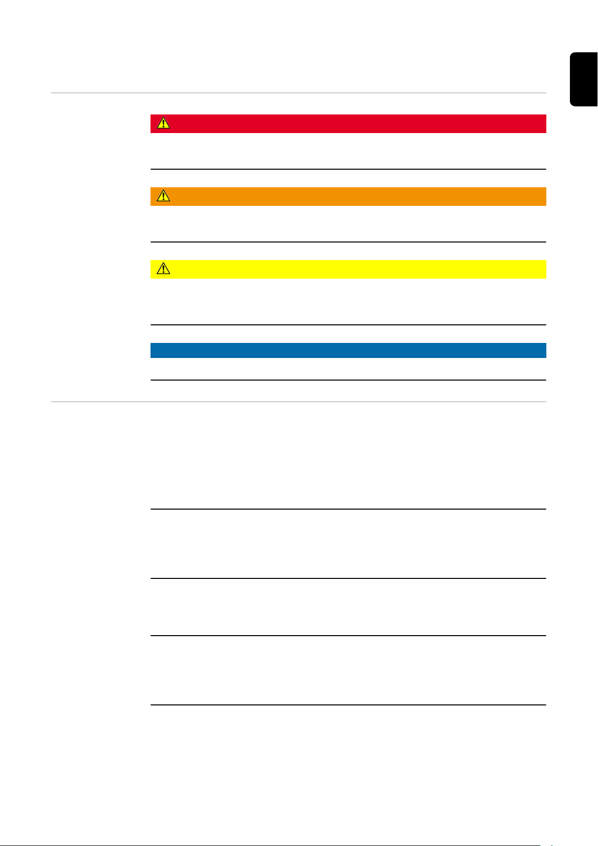
DANGER!
Indicates an immediate danger.
Death or serious injury may result if appropriate precautions are not taken.
▶
WARNING!
Indicates a possibly dangerous situation.
Death or serious injury may result if appropriate precautions are not taken.
▶
CAUTION!
Indicates a situation where damage or injury could occur.
Minor injury or damage to property may result if appropriate precautions are
▶
not taken.
NOTE!
Indicates the possibility of flawed results and damage to the equipment.
General The device has been manufactured using state-of-the-art technology and ac-
cording to recognized safety standards. If used incorrectly or misused, however,
it can cause
Injury or death to the operator or a third party
-
Damage to the device and other material assets belonging to the operating
-
company
Inefficient operation of the equipment
-
All persons involved in the commissioning, operation, maintenance, and servicing
of the device must
Be suitably qualified
-
Have knowledge of welding
-
Have completely read and followed these Operating Instructions
-
The Operating Instructions must always be at hand wherever the device is being
used. In addition to the Operating Instructions, all applicable local rules and regulations regarding accident prevention and environmental protection must also
be followed.
All safety and danger notices on the device must
Be kept in a legible state
-
Not be damaged/marked
-
Not be removed
-
Not be covered, pasted, or painted over
-
For the location of the safety and danger notices on the device, refer to the section headed "General" in the Operating Instructions for the device.
Before switching on the device, remove any faults that could compromise safety.
Your personal safety is at stake!
7

Intended Use The device is to be used exclusively for its intended purpose.
The device is intended exclusively for the welding process specified on the rating
plate.
Utilization for any other purpose, or in any other manner, shall be deemed to be
"not in accordance with the intended purpose." The manufacturer is not responsible for any damage resulting from improper use.
Proper use also means
Completely reading and obeying all instructions in the Operating Instruc-
-
tions
Completely reading and obeying all safety instructions and danger notices
-
Carrying out all the specified inspection and servicing work
-
Never use the device for the following applications:
Thawing pipes
-
Charging batteries
-
Starting motors
-
The device is designed for operation in industry and business. The manufacture
shall not be liable for any damage resulting from use in a living area.
The manufacture shall also not be liable for faulty or incorrect work results.
Environmental
Conditions
Obligations of
the Operating
Company
Operation or storage of the device outside the stipulated area will be deemed as
not in accordance with the intended purpose. The manufacturer accepts no liability for any damage resulting from improper use.
Temperature range of the ambient air:
During operation: -10°C to +40°C (14°F to 104°F)
-
During transport and storage: -20°C to +55°C (-4°F to 131°F)
-
Relative humidity:
Up to 50% at 40°C (104°F)
-
Up to 90% at 20°C (68°F)
-
Ambient air: free of dust, acids, corrosive gases or substances, etc.
Altitude above sea level: up to 2000 m (6561 ft. 8.16 in.)
The operating company must only allow persons to work with the device if they
Are familiar with the basic occupational safety and accident prevention regu-
-
lations and are trained in handling the device
Have read and understood these Operating Instructions, especially the sec-
-
tion "Safety Rules," and have confirmed this with their signature
Are trained according to the requirements for the work results
-
The safety-conscious work of the personnel must be checked regularly.
Obligations of
Personnel
8
All persons who are assigned to work with the device must do the following before beginning the work:
Follow the basic regulations for occupational safety and accident prevention
-
Read these Operating Instructions, especially the section "Safety Rules," and
-
confirm that they have understood and will follow them by signing
Before leaving the workplace, ensure that no personal injury or property damage
can occur in one's absence.

Grid Connection Devices with a high output can influence the energy quality of the grid due to
their current consumption.
This may affect a number of device types in terms of:
connection restrictions
-
-
criteria regarding maximum permissible grid impedance
-
criteria regarding the minimum required short-circuit power
*)
both at the interface with the public grid
*)
*)
See technical data
In this case, the operator or the person using the device should check whether or
not the device is allowed to be connected, where appropriate through discussion
with the power supply company.
IMPORTANT! Ensure secure grounding of the grid connection!
EN-US
Personal Protection and Protection of Others
You are exposed to numerous hazards while handling the device, for example:
Flying sparks and pieces of hot metal
-
Arc radiation that poses a risk of injury to the eyes and skin
-
Hazardous electromagnetic fields that pose a risk of death for individuals
-
with pacemakers
Electrical risks from grid current and welding current
-
Increased noise exposure
-
Harmful welding fumes and gases
-
Wear suitable protective clothing when dealing with the device. The protective
clothing must have the following properties:
Flame resistant
-
Insulating and dry
-
Covering the entire body and in good condition with no damage
-
Safety helmet
-
Cuffless pants
-
Protective clothing involves the following:
Protecting the face and eyes from UV radiation, heat and flying sparks with a
-
face guard featuring a regulation-compliant filter
Wearing regulation-compliant protective goggles with side protection behind
-
the face guard
Wearing rigid, wet-insulating footwear
-
Protecting hands with appropriate gloves (featuring electrical insulation and
-
thermal protection)
Wearing ear protection to reduce noise exposure and protect against injury
-
Danger from toxic gases and vapors
Keep persons, especially children, away during the operation of the devices and
during the welding process. If persons are in the vicinity, however:
Instruct them about all hazards (blinding hazard due to arcs, risk of injury
-
from flying sparks, welding fumes hazardous to health, noise exposure, possible hazard due to grid current or welding current, etc.)
Provide suitable protective equipment or
-
Construct suitable protective walls and curtains.
-
The fumes produced during welding contain toxic gases and vapors.
Welding fumes contain substances that cause cancer, as stated in monograph
118 from the International Agency for Research on Cancer.
9

Use at-source extraction source and a room extraction system.
If possible, use a welding torch with an integrated extraction device.
Keep your head out of the welding fumes and gases.
Take the following precautionary measures for fumes and harmful gases:
Do not breathe them in.
-
Extract them from the work area using appropriate equipment.
-
Ensure that there is a sufficient supply of fresh air. Ensure that there is a ventilation flow rate of at least 20 m³ per hour.
Use a welding helmet with air supply if there is insufficient ventilation.
If there is uncertainty as to whether the extraction capacity is sufficient, compare the measured toxic emission values against the permissible limit values.
The following components are factors that determine how toxic the welding
fumes are:
The metals used for the workpiece
-
Electrodes
-
Coatings
-
Cleaning agents, degreasers, and the like
-
The welding process used
-
Consult the corresponding material safety data sheets and manufacturer's instructions for the components listed above.
Danger from Flying Sparks
Recommendations for exposure scenarios, risk management measures and
identifying working conditions can be found on the European Welding Association website under Health & Safety (https://european-welding.org).
Keep flammable vapors (such as solvent vapors) out of the arc radiation range.
When no welding is taking place, close the valve of the shielding gas cylinder or
the main gas supply.
Flying sparks can cause fires and explosions.
Never undertake welding near flammable materials.
Flammable materials must be kept at least 11 meters (36 ft. 1.07 in.) from the
arc or protected with a certified cover.
Keep suitable, tested fire extinguishers on hand.
Sparks and pieces of hot metal may also get into surrounding areas through
small cracks and openings. Take appropriate measures to ensure that there is no
risk of injury or fire.
Do not undertake welding in areas at risk of fire and explosion, or on sealed
tanks, drums, or pipes if these have not been prepared in accordance with corresponding national and international standards.
Risks from grid
current and
welding current
10
Do not undertake welding on containers in which gases, fuels, mineral oils, and
the like are/were stored. Residues pose a risk of explosion.
An electric shock can be fatal.
Do not touch voltage-carrying parts inside or outside the device.

During MIG/MAG welding and TIG welding, the welding wire, the wirespool, the
feed rollers, as well as all pieces of metal that are in contact with the welding
wire, are live.
Always place the wirefeeder on a sufficiently insulated base or use a suitable insulating wirefeeder holder.
Ensure suitable personal protection with dry temporary backing or cover with
sufficient insulation against the ground potential. The temporary backing or cover must completely cover the entire area between the body and the ground potential.
All cables and leads must be secured, undamaged, insulated, and adequately dimensioned. Replace loose connections and scorched, damaged, or inadequately
dimensioned cables and leads immediately.
Before every use, check power connections for secure fit by hand.
In the case of power cables with bayonet connectors, turn the power cable by at
least 180° around the longitudinal axis and pretension.
Do not wrap cables or leads around your body or parts of the body.
Concerning the electrode (rod electrode, tungsten electrode, welding wire, etc.)
Never immerse it in liquids to cool it
-
Never touch it when the power source is switched on.
-
The open circuit voltage of a welding system may double, for example, between
the electrodes of two welding systems. Touching the potentials of both electrodes at the same time may be life-threatening in some cases.
EN-US
Have the grid and device supply lead regularly inspected by an electrician to ensure that the ground conductor is functioning properly.
Protection class I devices require a grid with a ground conductor and a connector
system with ground conductor contact for proper operation.
Operation of the device on a grid without a ground conductor and on a socket
without a ground conductor contact is only permitted if all national regulations
for protective separation are observed.
Otherwise, this is considered gross negligence. The manufacturer accepts no liability for any damage resulting from improper use.
Use suitable equipment to ensure that the workpiece is sufficiently grounded if
necessary.
Switch off unused devices.
When working at elevated heights, wear a safety harness to prevent falls.
Before working on the device, switch off the device and remove the grid plug.
Secure the device to prevent the grid plug from being connected and switched
on again by applying a clearly legible and understandable warning sign.
After opening the device:
Discharge all electrically charged components
-
Ensure that all components are disconnected from the power supply.
-
If work is needed on voltage-carrying parts, bring in a second person who will
switch off the main switch at the correct time.
11

Stray welding
currents
If the following instructions are not observed, stray welding currents may occur,
which pose a risk of the following:
Fire
-
Overheating of parts connected to the workpiece
-
Irreparable damage to ground conductors
-
Damage to the device and other electrical equipment
-
Ensure that the workpiece clamp is securely connected to the workpiece.
Secure the workpiece clamp as close to the spot to be welded as possible.
Position the device with sufficient insulation against electrically conductive environments, e.g., insulation against electrically conductive floors or electrically conductive mounts.
Observe the following when using power distribution boards, twin-head mounts,
etc.: Even the electrode of the welding torch/electrode holder not in use carries
electric potential. Ensure that there is sufficient insulation when the unused
welding torch/electrode holder is stored.
In automated MIG/MAG applications, only guide the wire electrode from the
welding wire drum, large spool, or wirespool to the wirefeeder with insulation.
EMC Device
Classifications
EMC measures In certain cases, even though a device complies with the standard limit values for
Devices in emission class A:
Are only designed for use in industrial settings
-
Can cause line-bound and radiated interference in other areas
-
Devices in emission class B:
Satisfy the emissions criteria for residential and industrial areas. This is also
-
true for residential areas in which the energy is supplied from the public lowvoltage grid.
EMC device classification as per the rating plate or technical data.
emissions, it may affect the application area for which it was designed (e.g., when
there is sensitive equipment at the same location, or if the site where the device
is installed is close to either radio or television receivers).
If this is the case, then the operating company is obliged to take appropriate action to rectify the situation.
Test and assess the immunity of equipment in the vicinity of the device in accordance with national and international provisions. Examples of interferenceprone equipment that could be affected by the device:
Safety devices
-
Grid power lines, signal lines, and data transfer lines
-
IT and telecommunications equipment
-
Devices for measuring and calibrating
-
12
Supporting measures to avoid EMC problems:
Grid power supply
1.
If electromagnetic interference occurs despite a grid connection that
-
complies with regulations, take additional measures (e.g., use a suitable
grid filter).
Welding power-leads
2.
Keep them as short as possible
-
Route them close together (also to avoid EMF problems)
-
Route them far from other lines
-

Equipotential bonding
3.
Workpiece grounding
4.
If necessary, establish grounding using suitable capacitors.
-
Shield, if necessary
5.
Shield other devices in the vicinity
-
Shield the entire welding installation
-
EMF measures Electromagnetic fields may cause health problems that are not yet known:
Effects on the health of persons close by, e.g., those with pacemakers and
-
hearing aids
Persons with pacemakers must seek advice from their doctor before staying
-
in the immediate vicinity of the device and the welding process
Keep distances between welding power-leads and the head/torso of the
-
welder as great as possible for safety reasons
Do not carry welding power-leads and hosepacks over your shoulder or wrap
-
them around your body or body parts
EN-US
Particular hazard areas
Keep hands, hair, loose clothing, and tools away from moving parts, such as:
Fans
-
Gears
-
Rollers
-
Shafts
-
Wirespools and welding wires
-
Do not reach into rotating gears of the wire drive or into rotating drive parts.
Covers and side panels must only be opened/removed during maintenance and
repair work.
During operation
Ensure that all covers are closed, and all side parts have been mounted prop-
-
erly.
Keep all covers and side parts closed.
-
The protrusion of welding wire from the welding torch represents a high risk of
injury (cuts to the hand, facial and eye injuries, etc.).
Therefore, always hold the welding torch away from the body (devices with
wirefeeder) and use suitable protective goggles.
Do not touch the workpiece during or after welding – risk of burns.
Slag may fly off cooling workpieces. Therefore, also wear regulation-compliant
protective equipment when reworking workpieces and ensure that other persons
are sufficiently protected.
Leave the welding torch and other parts with a high operating temperature to
cool before working on them.
Special regulations apply in areas at risk of fire or explosion
– follow the appropriate national and international regulations.
Power sources for work in areas with increased electrical hazard (e.g., boilers)
must be labeled with the symbol (Safety). However, the power source may not be
located in such areas.
Risk of scalding due to leaking coolant. Switch off the cooling unit before disconnecting connections for the coolant supply or return.
13

When handling coolant, observe the information on the coolant safety data
sheet. The coolant safety data sheet can be obtained from your service center or
via the manufacturer's website.
Only use suitable load-carrying equipment from the manufacturer to transport
devices by crane.
Attach chains or ropes to all designated attachments of the suitable load-
-
carrying equipment.
Chains or ropes must be the smallest angle possible from vertical.
-
Remove gas cylinder and wirefeeder (MIG/MAG and TIG devices).
-
In the event of crane attachment of the wirefeeder during welding, always use a
suitable, insulating wirefeeder hoisting attachment (MIG/MAG and TIG devices).
If the device is equipped with a carrier belt or handle, then this is used exclusively for transport by hand. The carrier belt is not suitable for transport by crane,
counterbalanced lift truck, or other mechanical lifting tools.
All lifting equipment (belts, buckles, chains, etc.), which is used in association
with the device or its components, must be checked regularly (e.g., for mechanical damage, corrosion, or changes due to other environmental influences).
The test interval and scope must at least comply with the respective valid national standards and guidelines.
There is a risk of colorless, odorless shielding gas escaping without notice if an
adapter is used for the shielding gas connection. Use suitable Teflon tape to seal
the thread of the shielding gas connection adapter on the device side before installation.
Requirement for
the shielding gas
Danger from
Shielding Gas
Cylinders
Especially with ring lines, contaminated shielding gas can cause damage to
equipment and reduce welding quality.
Meet the following requirements regarding shielding gas quality:
Solid particle size < 40 µm
-
Pressure condensation point < -20 °C
-
Max. oil content < 25 mg/m³
-
Use filters if necessary.
Shielding gas cylinders contain compressed gas and may explode if damaged.
Shielding gas cylinders are an integral part of the welding equipment, so they
must be handled very carefully.
Protect shielding gas cylinders with compressed gas from excessive heat, mechanical impact, slag, open flames, sparks, and arcs.
Mount the shielding gas cylinders vertically and secure them in accordance with
instructions so they cannot fall over.
Keep shielding gas cylinders away from welding or other electrical circuits.
Never hang a welding torch on a shielding gas cylinder.
Never touch a shielding gas cylinder with an electrode.
14
Risk of explosion: Never weld on a compressed shielding gas cylinder.
Always use suitable shielding gas cylinders for the application in question and the
correct matching accessories (controller, hoses, and fittings, etc.) Only use
shielding gas cylinders and accessories that are in good condition.

If a valve on a shielding gas cylinder is open, turn your face away from the outlet.
When no welding is taking place, close the valve of the shielding gas cylinder.
Leave the cap on the valve of the shielding gas cylinder when the cylinder is not
connected.
Follow the manufacturer's instructions and applicable national and international
provisions for shielding gas cylinders and accessories.
EN-US
Danger Posed by
Shielding Gas
Leak
Safety Measures
at the Setup
Location and
During Transport
Risk of asphyxiation due to uncontrolled shielding gas leak
Shielding gas is colorless and odorless and may suppress the oxygen in the ambient air in the event of leakage.
Ensure there is a sufficient supply of fresh air with a ventilation flow rate of
-
at least 20 m³ per hour.
Please observe the safety and maintenance information for the shielding gas
-
cylinder or the main gas supply.
When no welding is taking place, close the valve of the shielding gas cylinder
-
or the main gas supply.
Always check the shielding gas cylinder or main gas supply for uncontrolled
-
gas leakage before each start-up.
A toppling device can be deadly! Set up the device securely on an even, solid surface
The maximum permitted tilt angle is 10°.
-
Special regulations apply in areas at risk of fire or explosion
Follow the appropriate national and international regulations.
-
Use instructions and checks within the company to ensure that the vicinity of the
workplace is always clean and organized.
Only set up and operate the device in accordance with the protection class
shown on the rating plate.
When setting up the device, ensure that there is an all-round clearance of 0.5 m
(1 ft. 7.69 in.) to allow cooling air to circulate unhindered.
Take care to ensure that the applicable national and regional guidelines and accident prevention regulations are observed when transporting the device, especially guidelines concerning hazards during transport and shipment.
Do not lift or transport any active devices. Switch off devices before transport or
lifting.
Before transporting the device, completely drain the coolant and dismantle the
following components:
wirefeeder
-
wirespool
-
shielding gas cylinder
-
It is essential to conduct a visual inspection of the device to check for damage
after it has been transported but before commissioning. Have any damage repaired by trained service technicians before commissioning the device.
15

Safety Measures
in Normal Operation
Only operate the device when all safety devices are fully functional. If the safety
devices are not fully functional, there is a danger of:
Injury or death to the operator or a third party
-
Damage to the device and other material assets belonging to the operating
-
company
Inefficient operation of the device
-
Safety devices that are not fully functional must be repaired before the device is
switched on.
Never bypass or disable safety devices.
Before switching on the device, ensure that no one can be put in danger.
The device must be examined at least once a week for externally detectable damage and functionality of the safety devices.
Always secure the shielding gas cylinder well and remove before transporting by
crane.
Only the original coolant from the manufacturer is suitable for use in our devices
due to its properties (electrical conductivity, anti-freeze, material compatibility,
flammability, etc.)
Only use appropriate original coolant from the manufacturer.
Do not mix original coolant from the manufacturer with other coolants.
Maintenance and
repair
Only connect system components from the manufacturer to the cooling unit circuit.
If there is damage due to use of other system components or other coolants, the
manufacturer accepts no liability for this and all warranty claims are forfeited.
Cooling Liquid FCL 10/20 is not flammable. The ethanol-based coolant is flam-
mable in certain conditions. Only transport the coolant in closed original containers and keep away from sources of ignition.
Properly dispose of used coolant according to national and international regulations. The coolant safety data sheet can be obtained from your service center or
via the manufacturer’s website.
When the system is cool, always check the coolant level before starting welding.
It is impossible to guarantee that bought-in parts are designed and manufactured to meet the demands made of them, or that they satisfy safety requirements.
Use only original spare and wearing parts (also applies to standard parts).
-
Do not carry out any modifications, alterations, etc. to the device without the
-
manufacturer's consent.
Components that are not in perfect condition must be replaced immediately.
-
When ordering, please give the exact designation and part number as shown
-
in the spare parts list, as well as the serial number of your device.
16
The housing screws provide the ground conductor connection for earthing the
housing parts.
Only use original housing screws in the correct number and tightened to the specified torque.

Safety Inspection
Disposal To comply with European directives and national law, waste electrical and elec-
The manufacturer recommends that a safety inspection of the device be performed at least every 12 months.
The manufacturer recommends calibrating power sources within the same 12month interval.
A safety inspection by a certified electrician is recommended:
After changes
-
After alterations
-
After repair, care, and maintenance
-
At least every 12 months
-
For the safety inspection, follow the appropriate national and international
standards and guidelines.
You can obtain more information about the safety inspection and calibration
from your service center. The service center will provide the necessary documents upon request.
tronic equipment must be collected separately and sent for environmentallyfriendly recycling. Used devices must be returned to a distributor or an approved
collection and recycling facility in your area. Proper disposal of used devices promotes the sustainable recycling of material resources. Ignoring this may have potentially adverse effects on the environment and your health.
EN-US
Packaging materials
Materials collected separately. Check the regulations in your area. Reduce the
volume of cardboard.
Safety symbols Devices with the CE label satisfy the essential requirements of the low-voltage
and electromagnetic compatibility directive (e.g., relevant product standards of
the EN 60974 series).
Fronius International GmbH declares that the device complies with Directive
2014/53/EU. The full text of the EU Declaration of Conformity is available on the
following website: http://www.fronius.com
Devices marked with the CSA test mark satisfy the requirements of the relevant
standards for Canada and the USA.
Data backup The user is responsible for backing up any changes made to the factory settings.
The manufacturer accepts no liability for any deleted personal settings.
Copyright Copyright of these Operating Instructions remains with the manufacturer.
Text and illustrations were accurate at the time of printing. Fronius reserves the
right to make changes. The contents of the Operating Instructions shall not
provide the basis for any claims whatsoever on the part of the purchaser. If you
have any suggestions for improvement, or can point out any mistakes that you
have found in the Operating Instructions, we will be most grateful for your comments.
17

18

General information
19

20

General
Device concept The TransSteel (TSt) 3000c Pulse
power source is a fully digitized, microprocessor-controlled inverter power
source.
A modular design and ability to easily
extend the system guarantee a high
degree of flexibility. The device is de-
signed for the following welding processes:
MIG/MAG pulse welding
-
MIG/MAG standard synergic weld-
-
ing
TIG welding
-
Manual metal arc welding
-
The device has a "Power limitation" safety feature. This means that the power
source can be operated at the power limit without compromising process safety.
For details, refer to the "Welding operations" chapter.
EN-US
Operating principle
Application
areas
The central control and regulation unit of the power sources is coupled with a digital signal processor. The central control and regulation unit and signal processor control the entire welding process.
During the welding process, the actual data is measured continuously and the
device responds immediately to any changes. Control algorithms ensure that the
desired target state is maintained.
This results in:
A precise welding process
-
A high degree of reproducibility on all results
-
Excellent weld properties.
-
The TransSteel 3000c Pulse is used in trade and industry for manual applications
with classical steel and galvanized sheet metal.
The power source is designed for:
Mechanical and equipment engineering
-
Steel construction
-
Plant and container construction
-
Metal and portal construction
-
Rail vehicle construction
-
Metalworking trades
-
21
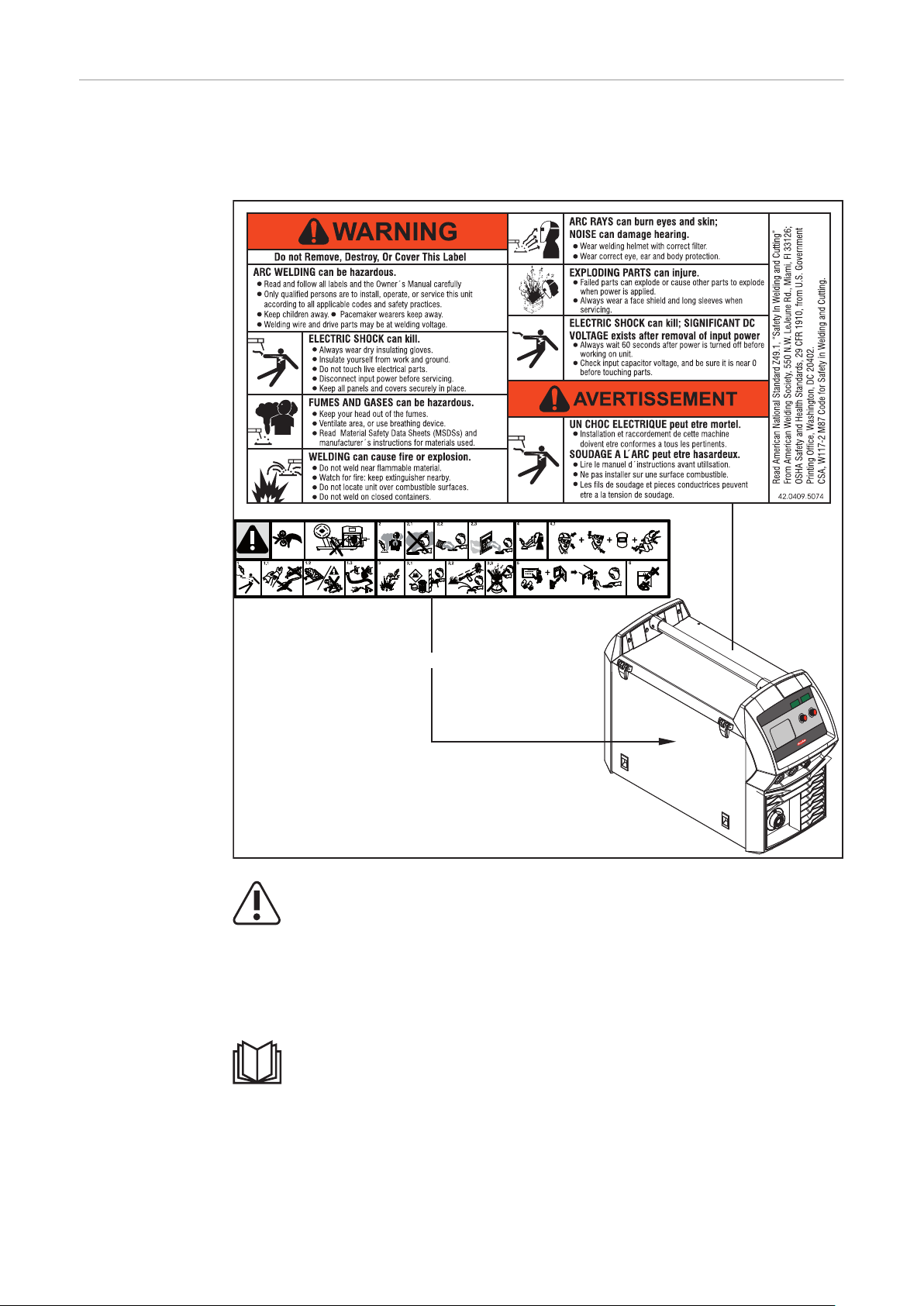
Warning notices
40,0006,3035
inside
on the device
There are warning notices and safety symbols on the power sources. These warning notices and safety symbols must not be removed or painted over. They warn
against incorrect operation, as this may result in serious injury and property damage.
22
Welding is dangerous. The following basic requirements must be met:
Adequate welding qualifications
-
Appropriate protective equipment
-
Exclusion of unauthorized persons
-
Do not use the functions described here until you have fully read and understood
the following documents:
These Operating Instructions
-
All system component Operating Instructions, especially the safety rules
-

Description of
A B
the warnings on
the device
Warning notices are attached to the device for certain device versions.
The arrangement of the symbols may vary.
! Warning! Caution!
The symbols represent possible dangers.
A Drive rollers can injure fingers.
B The welding wire and drive parts are under welding voltage during opera-
tion.
Keep hands and metal objects away!
EN-US
1. An electric shock can be fatal.
1.1 Wear dry, insulating gloves. Do not touch the wire electrode with bare
hands. Do not wear wet or damaged gloves.
1.2 Use a base that is insulated from the floor and work area to protect
against electric shock.
1.3 Before working on the device, switch off the device and remove the mains
plug or disconnect the power supply.
2. Inhalation of welding fumes can be harmful to health.
2.1 Keep your face away from any welding fumes.
23
2.2 Use forced-air ventilation or local extraction to remove welding fumes.
xx,xxxx,xxxx *
2.3 Remove welding fumes with a fan.
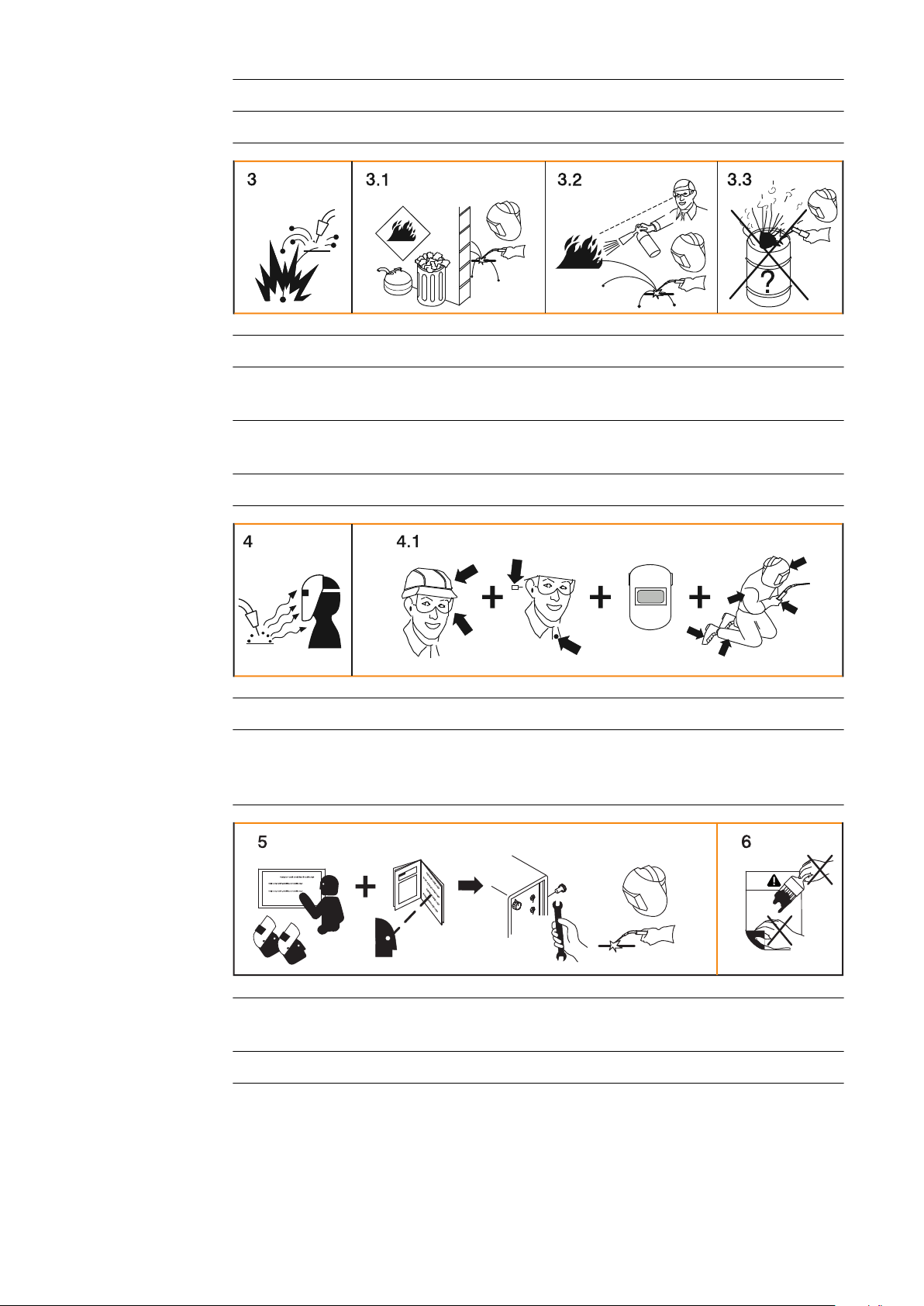
3. Welding sparks can cause an explosion or fire.
3.1 Keep flammable materials away from the welding process. Do not perform
welding near flammable materials.
3.2 Welding sparks can cause a fire. Have fire extinguishers ready. If neces-
sary, have a supervisor ready who can operate the fire extinguisher.
3.3 Do not weld on drums or closed containers.
4. Arc rays can burn the eyes and injure the skin.
4.1 Wear headgear and protective goggles. Use ear protection and wear a
shirt collar with button. Use a welding helmet with the correct tinting.
Wear suitable protective clothing over the entire body.
5. Before working on the machine or welding:
undertake training on the device and read the instructions!
6. Do not remove or paint over the sticker with the warnings.
* Manufacturer order number of the sticker
24

Welding processes, procedures, and welding characteristics for MIG/MAG welding
General In order to process a wide range of materials effectively, various welding pro-
cesses, procedures, and welding characteristics are available on the power
source.
Brief description
of MIG/MAG
standard synergic welding
MIG/MAG standard synergic
MIG/MAG standard synergic welding is a MIG/MAG welding process covering the
entire power range of the power source with the following arc types:
Dip transfer arc
Droplet transfer occurs in the lower power range during the short circuit.
Intermediate arc
The droplet increases in size at the end of the wire electrode and is transferred in
the mid power range during the short circuit.
Spray arc
A short circuit-free transfer of material in the high power range.
EN-US
Brief description
of MIG/MAG
pulsed synergic
welding
Brief description
of SynchroPulse
welding
MIG/MAG pulsed synergic
MIG/MAG pulsed synergic welding is a pulsed arc process with a controlled material transfer.
In the base current phase, the energy input is reduced to such an extent that the
arc barely burns steadily and the surface of the workpiece is preheated. In the
pulsing current phase, an accurately timed current pulse guarantees a precise
detachment of the weld material droplet.
This principle guarantees low-spatter welding and precise operation throughout
the entire power range.
SynchroPulse is available for the standard synergic and pulsed synergic processes.
The cyclic change of the welding power between two operating points with SynchroPulse achieves a finely rippled weld appearance and a non-continuous heat
input.
25

System components
(1)
(2)
(3)
(4)
(5)
(6)
(7)
General The power sources can be operated with various system components and op-
tions. This makes it possible to optimize procedures and to simplify machine
handling and operation, depending on the field of application for the power
source.
Safety
Overview
WARNING!
Danger from incorrect operation and work that is not carried out properly.
This can result in serious personal injury and damage to property.
All the work and functions described in this document must only be carried
▶
out by technically trained and qualified personnel.
Read and understand this document in full.
▶
Read and understand all safety rules and user documentation for this equip-
▶
ment and all system components.
(1) MIG/MAG welding torch
(2) Stabilization of the gas cylinder holder
(3) Power source
(4) Cooling unit
(5) Trolley with gas cylinder holder
(6) Grounding and electrode cable
(7) TIG welding torch
26

Operating controls and connec-
tions
27

28

Control Panel
General The functions are all arranged in a logical way on the control panel. The individual
parameters required for welding can be
Selected by means of buttons
-
Changed using buttons or the selection dial
-
Shown on the digital display during welding.
-
Due to the synergic function, all other parameters are also adjusted if a single
parameter is changed.
NOTE!
Because of software updates, certain functions may be available for your device
but not described in these Operating Instructions or vice versa.
In addition, individual figures may also differ slightly from the operating elements of your device. However, the function of these operating elements is
identical.
EN-US
Safety
WARNING!
Danger from incorrect operation and work that is not carried out properly.
This can result in serious personal injury and damage to property.
All the work and functions described in this document must only be carried
▶
out by technically trained and qualified personnel.
Read and understand this document in full.
▶
Read and understand all safety rules and user documentation for this equip-
▶
ment and all system components.
29
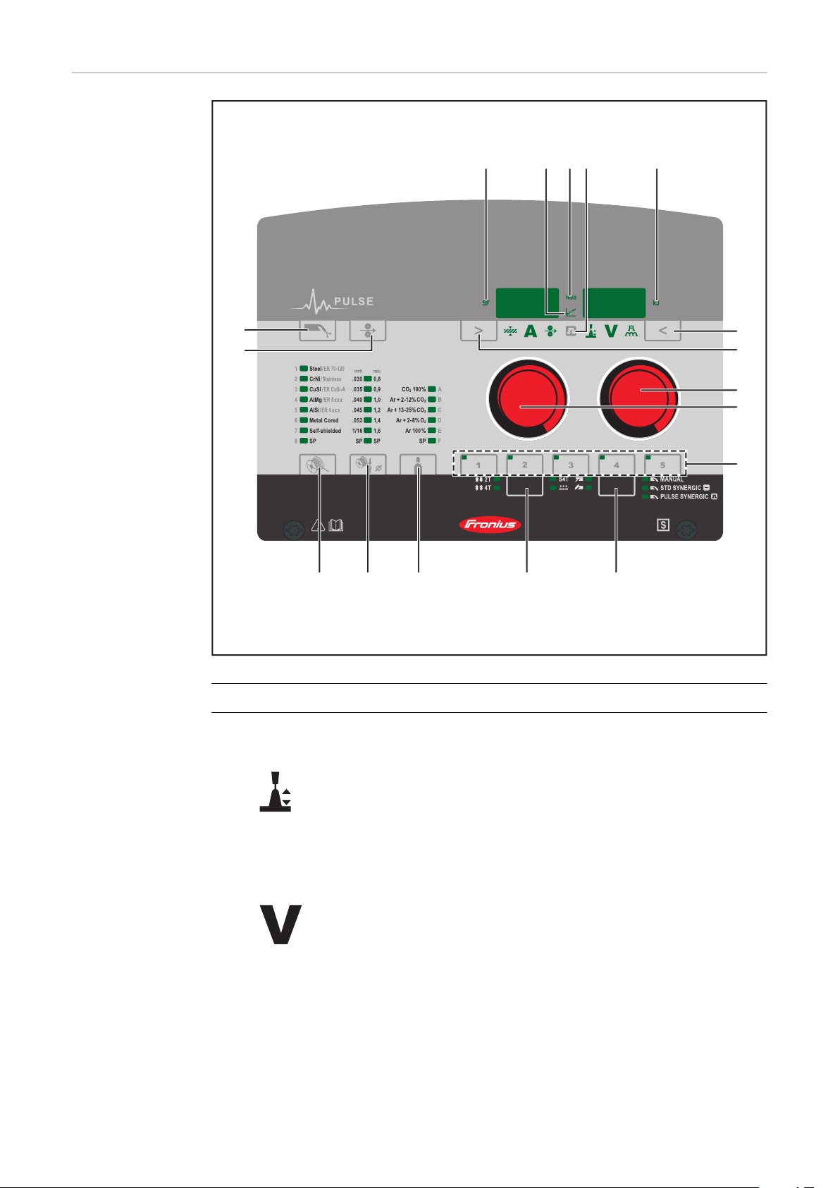
Control panel
(1)
(2)
(3)
(4)
(5)
(6)(7)
(14)(13) (17)
(12)
(11)
(10) (8)
(9)
(15)(16)
No. Function
(1) "Parameter selection" button (right)
a) for selecting the following parameters
Arc length correction
For correcting the arc length
Welding voltage in V *)
Before welding begins, the device automatically displays a standard value
based on the programmed parameters. The actual value is displayed during welding.
30

Pulse / arc-force dynamic correction
For continuously correcting the droplet detachment force in MIG/MAG
pulsed synergic welding
- ... reduced droplet detachment force
0 ... neutral droplet detachment force
+ ... increased droplet detachment force
For influencing the short-circuiting dynamic at the instant of droplet
transfer in MIG/MAG standard synergic welding, MIG/MAG standard
manual welding, and manual metal arc welding
- ... harder and more stable arc
0 ... neutral arc
+ ... soft and low-spatter arc
b) for changing parameters in the Setup menu
(2) "Parameter selection" button (left)
a) for selecting the following parameters
EN-US
Sheet thickness
Sheet thickness in mm or in.
If the welding current to be selected is not known, it is sufficient to enter
the sheet thickness. The required welding current and any other parameters marked with *) will then be adjusted automatically.
Welding current *)
Welding current in A
Before welding begins, the device automatically displays a standard value
based on the programmed parameters. The actual value is displayed during welding.
Wire speed
*)
Wire speed in m/min or ipm.
b) for changing parameters in the Setup menu
(3) Selection dial (right)
For changing the arc length correction, welding voltage, and arc-force dynamic parameters
31

For changing parameters in the Setup menu
(4) Selection dial (left)
For changing the sheet thickness, welding current, and wire speed parameters
For selecting parameters in the Setup menu
(5) EasyJob save buttons
For saving up to 5 operating points
(6)
"Process" button
**)
For selecting the welding process
MIG/MAG standard manual welding
MIG/MAG standard synergic welding
MIG/MAG pulsed synergic welding
TIG welding
Manual metal arc welding
(7) "Mode" button
For selecting the operating mode
2-step mode
4-step mode
Special 4-step mode
32

Spot welding/stitch welding
(8) "Shielding gas" button
For selecting the shielding gas used. The SP parameter is reserved for additional shielding gases.
When the shielding gas is selected, the LED behind the corresponding
shielding gas lights up.
(9) "Wire diameter" button
For selecting the wire diameter used. The SP parameter is reserved for
additional wire diameters.
When the wire diameter is selected, the LED behind the corresponding
wire diameter lights up.
(10) "Material" button
For selecting the filler metal used. The SP parameter is reserved for additional materials.
When the material type is selected, the LED behind the corresponding
filler metal lights up.
EN-US
(11) "Wire threading" button
Press and hold the button:
Gasless wire threading into the torch hosepack
While the button is being held, the wire drive operates at feeder inching
speed.
(12) Gas-test button
For setting the required gas volume on the gas pressure regulator.
Tap the button once: shielding gas flows out
Tap the button again: shielding gas flow stops
If the Gas-test button is not tapped again, the shielding gas flow will stop
after 30 s.
(13) SF - spot/stitch/SynchroPulse welding indicator
Lights up if a value is set for the spot welding/stitch welding time
-
(SPt) setup parameter when spot welding or stitch welding mode is
activated
Lights up if a value is set for the Frequency (F) setup parameter when
-
the MIG/MAG synergic welding process is activated.
(14) Intermediate arc indicator
A spatter-prone "intermediate arc" occurs between the dip transfer arc
and the spray arc. The intermediate arc indicator lights up to alert you to
this critical area.
(15) HOLD indicator
At the end of each welding operation, the actual values for welding current and welding voltage are stored - the "HOLD" indicator lights up.
33

(16) Pulse indicator
Lights up when the MIG/MAG pulsed synergic welding process is selected
(17) Real Energy Input
For displaying the energy applied during the welding operation.
The Real Energy Input indicator must be activated in level 2 of the Setup
menu – EnE parameter. The value continuously rises during welding in line
with the permanently increasing energy input. The final value is stored
after the end of welding until welding starts again or the power source is
switched back on - the HOLD indicator lights up.
*) During the MIG/MAG standard synergic welding process and MIG/MAG
pulsed synergic welding process, if one of these parameters is selected,
then the synergic function ensures that all other parameters, including
the welding voltage parameter, are adjusted automatically.
**) In conjunction with the VRD option, the indicator of the currently selec-
ted welding process is also used as status indicator:
The indicator lights up continuously: the voltage reduction (VRD) is
-
active and limits the output voltage to less than 35 V.
The indicator flashes as soon as a welding operation occurs, which can
-
cause the output voltage to be greater than 35 V.
34

Service para-
+
meters
Various service parameters can be retrieved by pressing the "Parameter selection" buttons at the same time.
Opening the display
EN-US
1
Selecting parameters
2
Available parameters
Example:
1.00 | 4.21
Example:
2 | 491
Example:
r 2 | 290
The first parameter "Firmware version"
will be displayed, e.g., "1.00 | 4.21"
Use the "Mode" and "Process" buttons
or the left-hand selection dial to select
the required setup parameter
Explanation
Firmware version
Welding program configuration
Number of the currently selected
welding program
Example:
654 | 32.1
= 65,432.1 hours
= 65,432 hours 6 mins
Indicates the actual arc time since
first use
Note: The arc time indicator is not
suitable as a basis for calculating hiring fees or for warranty purposes, etc.
Example:
iFd | 0.0
Motor current for wire drive in A
The value changes as soon as the motor is running.
2nd 2. menu level for service technicians
35

Keylock A keylock can be selected to prevent the settings from being inadvertently
+
changed on the control panel. As long as the keylock is active:
Settings cannot be adjusted on the control panel
-
Only parameter settings can be retrieved
-
Any assigned "Save" button can be retrieved provided that an assigned "Save"
-
button was selected when the keylock was enabled
Activating/deactivating the keylock:
1
Keylock activated:
The message "CLO | SEd" appears on
the displays.
Keylock deactivated:
The message "OP | En" appears on the
displays.
The keylock can also be activated and deactivated using the keylock switch option.
36

Connections, Switches, and Mechanical Compon-
(1)
(2)
(3)
(4)
(5)
(6)
(7)
(11)
(8)
(9)
(10)
ents
Front and back
EN-US
(1) Welding torch connection
For connecting the welding torch
(2) Polarity reverser
For selecting the welding potential on the MIG/MAG welding torch
(3) (-) Current socket with bayonet latch
Used for
Connecting the grounding cable or polarity reverser for MIG/MAG
-
welding (depending on the wire electrode used)
Connecting the electrode cable or grounding cable for manual metal
-
arc welding (depending on the type of electrode used)
Connecting the TIG welding torch
-
(4) (+) Current socket with bayonet latch
Used for
Connecting the polarity reverser or grounding cable for MIG/MAG
-
welding (depending on the wire electrode used)
Connecting the electrode cable or grounding cable for manual metal
-
arc welding (depending on the type of electrode used)
Connecting the grounding cable for TIG welding
-
(5) LocalNet connection
Standardized connection for remote control
(6) Power switch
For switching the power source on and off
(7) TMC connection (TIG Multi Connector)
For connecting the TIG welding torch
(8) MIG/MAG shielding gas connection socket
(9) Mains cable with strain relief
For the shielding gas supply to the welding torch connection (1)
Not prefitted on all models
37

(10) EASY DOCUMENTATION label
(2)(1)
*
(11) TIG shielding gas connection socket
For the shielding gas supply for the (-) current socket (3)
Side view
No. Function
(1) Wirespool holder with brake
For holding standard wirespools
with a max. diameter of 300
mm (11.81 in.) and a max.
weight of 19 kg (41.89 lbs.)
(2) 4-roller drive
* Side panel not shown
38

Installation and Startup
39

40

Minimum equipment for welding operations
General Depending on the welding process, a minimum level of equipment is required to
work with the power source.
The following describes the welding processes and the corresponding minimum
equipment for welding operations.
EN-US
Gas-cooled
MIG/MAG welding
Water-cooled
MIG/MAG welding
Manual metal
arc welding
Power source
-
Grounding cable
-
Gas-cooled MIG/MAG welding torch
-
Gas connection (shielding gas supply)
-
Wire electrode
-
Power source
-
Cooling unit including coolant
-
Grounding cable
-
Water-cooled MIG/MAG welding torch
-
Gas connection (shielding gas supply)
-
Wire electrode
-
Power source
-
Grounding cable
-
Electrode holder
-
Rod electrodes
-
TIG DC Welding
Power source
-
Grounding cable
-
TIG welding torch with or without rocker switch
-
Gas connection (shielding gas supply)
-
Filler metal depending on application
-
41

Before installation and initial operation
Safety
WARNING!
Danger from incorrect operation and work that is not carried out properly.
This can result in serious personal injury and damage to property.
All the work and functions described in this document must only be carried
▶
out by technically trained and qualified personnel.
Read and understand this document in full.
▶
Read and understand all safety rules and user documentation for this equip-
▶
ment and all system components.
WARNING!
Danger from electrical current.
This can result in serious personal injury and damage to property.
Before starting work, switch off all devices and components involved, and
▶
disconnect them from the grid.
Secure all devices and components involved so they cannot be switched back
▶
on.
After opening the device, use a suitable measuring instrument to check that
▶
electrically charged components (such as capacitors) have been discharged.
Intended Use The power source is only intended for MIG/MAG, MMA and TIG welding. Any
other use is deemed to be "not in accordance with the intended purpose." The
manufacturer shall not be liable for any damage resulting from such improper
use.
Intended use also means:
Following all instructions in the Operating Instructions
-
Carrying out all the specified inspection and maintenance work
-
Setup regulations
The device has been tested according to degree of protection IP 23. This means:
Protection against penetration by solid foreign bodies with diameters > 12
-
mm (0.49 in.)
Protection against spraywater at any angle up to 60° from the vertical
-
The device can be set up and operated outdoors in accordance with degree of
protection IP 23.
Direct moisture (e.g., from rain) must be avoided.
WARNING!
Danger from machines toppling over or falling.
This can result in serious personal injury and damage to property.
Set up the device securely on an even, solid surface.
▶
Check all screw connections are tightly fastened after installation.
▶
42

WARNING!
Danger of electrical current due to electrically conductive dust in the device.
This can result in severe personal injury and damage to property.
Only operate the device if an air filter is fitted. The air filter is a very import-
▶
ant safety device for achieving IP 23 protection.
The ventilation channel is a very important safety device. When selecting the
setup location, ensure that the cooling air can enter or exit unhindered through
the vents on the front and back. Any electrically conductive dust (e.g., from
grinding work) must not be allowed to be sucked into the device.
Grid Connection The devices are designed for the grid voltage stated on the rating plate. If the
mains cable or mains plug has not been attached to your version of the appliance, these must be installed according to national standards. Fuse protection
for the grid lead can be found in the technical data.
CAUTION!
Danger due inadequately dimensioned electrical installations.
This can lead to serious damage
The grid lead and its fuse protection should be designed to suit the existing
▶
power supply.
The technical data on the rating plate should be followed.
EN-US
43

Connecting the Mains Cable
Stipulated mains
cables and
strain-relief
devices
Safety
The following mains cables are required to operate the power source:
Europe:
Cable cross-section 4G2.5
USA/Canada:
Cable cross-section AWG 12, extra-hard usage
Depending on the version, a strain-relief device corresponding to the cable crosssection is fitted on the power source.
The item numbers of the different cables can be found in the Spare Parts List.
WARNING!
Danger from work that is not carried out properly.
This can result in severe personal injury and damage to property.
The work described below may only be performed by trained specialist per-
▶
sonnel.
Follow national standards and guidelines.
▶
Connecting the
mains cable
CAUTION!
Danger from improperly prepared mains cable.
Short circuits and damage to property may result.
Fit ferrules to all phase conductors and the ground conductor of the
▶
stripped mains cable.
If no mains cable is connected, a mains cable that is suitable for the connection
voltage must be fitted before commissioning.
The ground conductor should be approx. 10 - 15 mm (0.4 - 0.6 in.) longer than
the phase conductors.
A graphic representation of the mains cable connection is provided in the following sections for fitting the strain-relief device. To connect the mains cable, proceed as follows:
Remove the side panel of the device
1
Push in the mains cable so that the ground conductor and phase conductor
2
can be properly connected to the block terminal.
Fit a ferrule to the ground conductor and phase conductor
3
Connect the ground conductor and phase conductor to the block terminal
4
Secure the mains cable with a strain-relief device
5
Fit the side panel of the device
6
44

Fitting the
1,2 Nm
strain-relief
device
1 2
EN-US
3 4
IMPORTANT! Tie the phase conductors near the block terminal using cable ties.
45

Fitting the
strain-relief
device for
Canada / US
1 2
3 4
IMPORTANT! Tie the phase conductors near the block terminal using cable ties.
46

Generator-Powered Operation
EN-US
Generatorpowered operation
The power source is generator-compatible.
The maximum apparent power S
of the power source must be known in order
1max
to select the correct generator output.
The maximum apparent power S
of the power source is calculated for 3-
1max
phase devices as follows:
S
= I
1max
I
and U1 according to the device rating plate and technical data
1max
The generator apparent power S
1max
x U1 x √3
needed is calculated using the following rule
GEN
of thumb:
S
GEN
= S
1max
x 1.35
A smaller generator can be used when not welding at full power.
IMPORTANT! The generator apparent power S
maximum apparent power S
of the power source!
1max
must not be less than the
GEN
NOTE!
The voltage delivered by the generator must never fall outside of the mains
voltage tolerance range.
The mains voltage tolerance is specified in the "Technical data" section.
47

Commissioning
Safety
An electric shock can be fatal.
If the power source is connected to the grid during installation, there is a danger
of serious personal injury and property damage.
▶
▶
Danger of electrical current due to electrically conductive dust in the device.
This can result in severe personal injury and damage to property.
▶
General Commissioning is described with reference to a manual, water-cooled MIG/MAG
application.
WARNING!
Only carry out work on the device when the power source's power switch is in
the - O - position.
Only carry out work on the device when the power source has been disconnected from the grid.
WARNING!
Only operate the device if an air filter is fitted. The air filter is a very important safety device for achieving IP 23 protection.
Information on
system components
The steps and activities described below include references to various system
components, such as
Trolley
-
Upright bracket
-
Cooling units
-
Welding torches, etc.
-
For more detailed information about installing and connecting the system components, please refer to the appropriate Operating Instructions for the system
components.
48

Assembling system components
WARNING!
Work performed incorrectly can cause serious injury and damage.
The following activities must only be carried out by trained and qualified per-
▶
sonnel.
Please note the information in the "Safety instructions" chapter!
▶
The following diagram shows an overview of how the individual system components are put together.
EN-US
Establishing a
ground earth
connection
1
49

Inserting/chan-
2
1
4
4
5
6
3
6
3
31
2
4
5
7
3
8
6
7
9
3
1
2
2
5
4
4
4
5
5
6
1
2
3
ging feed rollers
CAUTION!
Danger due to feed roller holders shooting upwards.
This could result in injury.
When unlocking the clamping lever, keep fingers away from the area to the
▶
left and right of the clamping lever.
1
2
CAUTION!
Danger due to open feed rollers.
This could result in injury.
After inserting/changing the feed rollers, always install the protective cover
▶
of the 4-roller drive.
3
4
50

Inserting the
wirespool
CAUTION!
Risk of injury due to springiness of spooled wire electrode.
When inserting the wirespool, hold the end of the wire electrode firmly to
▶
avoid injuries caused by the wire electrode springing back.
CAUTION!
Risk of injury from falling wirespool.
Ensure that the wirespool is fitted securely to the wirespool holder.
▶
CAUTION!
Danger of injury and property damage if the wirespool topples over because the
locking ring has been placed the wrong way around.
Always position the locking ring as shown in the diagram on the left.
▶
EN-US
1
51

Installing the
basket-type
spool
CAUTION!
Risk of injury due to springiness of spooled wire electrode.
When inserting the basket-type spool, hold the end of the wire electrode
▶
firmly to avoid injuries caused by the wire electrode springing back.
CAUTION!
Risk of injury from falling basket-type spool.
Make sure that the basket-type spool with basket-type spool adapter is fitted
▶
securely to the wirespool holder.
NOTE!
When working with basket-type spools, only use the basket-type spool adapter
supplied with the device.
CAUTION!
Danger of injury and property damage if the basket-type spool topples over because the locking ring has been placed the wrong way around.
Always position the locking ring as shown in the diagram on the left.
▶
52
CAUTION!
Danger of injury and damage to property due to falling basket-type spool.
Place the basket-type spool on the adapter provided in such a way that the
▶
bars on the spool are inside the adapter guideways.

1 2
EN-US
Feed in the wire
electrode
CAUTION!
Risk of injury due to springiness of spooled wire electrode.
When inserting the wire electrode into the 4-roller drive, hold the end of the
▶
wire electrode firmly to avoid injuries caused by the wire electrode springing
back.
CAUTION!
Risk of damage to the welding torch from sharp end of wire electrode.
Deburr the end of the wire electrode well before threading in.
▶
1 2
CAUTION!
Risk of injury from emerging wire electrode.
When pressing the "Wire threading" button or the torch trigger, keep the
▶
welding torch away from your face and body, and wear suitable protective
goggles.
IMPORTANT! To facilitate exact positioning of the wire electrode, the following
procedure is possible when the "Wire threading" button is pressed and held
down.
53

Fdi
1
2 3
4
5
2,5
1
t (s)
(m/min, ipm)
Hold the button for up to one
-
second ... the wire speed stays at 1
m/min or 39.37 ipm for the first
second.
Hold the button for up to 2.5
-
seconds ... after one second, the
wire speed increases evenly within
the next 1.5 seconds.
Hold the button for more than 2.5
-
seconds ... after 2.5 seconds, the
wire is fed at a constant rate equal
to the wire speed set for the Fdi
welding parameter.
If you release the "Wire threading" button and press it again before one second
has elapsed, the sequence starts again from the beginning. This makes it possible
to continuously position the wire at a low wire speed of 1 m/min or 39.37 ipm
where necessary.
If there is no wire threading button present, the torch trigger can be used in a
similar way. Before using the torch trigger for wire threading, proceed as follows:
Press the "Mode" button to select 2-step mode
1
Set the "Ito" parameter to "Off" in the Setup menu
2
CAUTION!
Danger of injury and damage from electric shock and from the wire electrode
emerging from the torch.
When you press the torch trigger:
Keep the welding torch away from your face and body
▶
Wear suitable protective goggles
▶
Do not point the welding torch at people
▶
Make sure that the wire electrode does not touch any conductive or groun-
▶
ded parts (e.g., housing, etc.)
IMPORTANT! If the torch trigger is pressed instead of the "Wire threading" button, the welding wire runs at the feeder creep speed (depending on the welding
program) for the first 3 seconds. After these 3 seconds, wirefeeding is briefly interrupted.
The welding system detects that the welding process should not start, but that
the wire is to be threaded in. At the same time, the gas solenoid valve closes, and
the welding voltage on the wire electrode is switched off.
54
If the torch trigger is kept pressed, wirefeeding restarts immediately without
shielding gas and welding voltage, and the process continues as described above.

2
4
5
3
1
3 4
1
EN-US
Setting the contact pressure
CAUTION!
Risk of contact pressure being too high.
This can result in severe damage to property and poor weld properties.
Set the contact pressure in such a way that the wire electrode is not de-
▶
formed but nevertheless ensures proper wirefeeding.
1
Contact pressure standard values for
U-groove rollers:
Steel: 4 - 5
CrNi: 4 - 5
Tubular covered electrodes: 2 - 3
55

Adjust the brake
4
6
7
1
2
STOP
3
5
2
1
2
4
STOP
OK
1
3
NOTE!
After releasing the wire threading button, the wirespool must stop unreeling.
If it continues unreeling, readjust the brake.
▶
1
3
2
Design of the
brake
56
WARNING!
Danger from incorrect installation.
This can result in severe personal injury and damage to property.
Do not dismantle the brake.
▶
Maintenance and servicing of
▶
brakes is to be carried out by
trained, qualified personnel only.
The brake is only available as a complete unit.
The illustration of the brake is for information purposes only.

Setting the date
and time when
starting for the
first time
After switching on the power source for the first time, the date and time must be
set. For this purpose, the power source changes to the second level of the service menu; the yEA parameter is selected.
To set the date and time see page 97, step 5
EN-US
57

58

MIG/MAG welding
59

60

Power Limitation
Safety function "Power limitation" is a safety function for MIG/MAG welding. This means that the
power source can be operated at the power limit whilst maintaining process
safety.
Wire speed is a determining parameter for welding power. If it is too high, the arc
gets smaller and smaller and may be extinguished. In order to prevent this, the
welding power is lowered.
If the "MIG/MAG standard synergic welding" or "MIG/MAG pulsed synergic welding" process is selected, the symbol for the "Wire speed" parameter flashes as
soon as the safety function trips. The flashing continues until the next welding
start-up, or until the next parameter change.
If the "Wire speed" parameter is selected, for example, the reduced value for wire
speed is displayed.
EN-US
61

MIG/MAG Operating Modes
General
Symbols and explanations
WARNING!
Operating the device incorrectly can cause serious injury and damage to property.
Do not use the functions described here until you have fully read and under-
▶
stood the Operating Instructions.
Do not use the functions described here until you have fully read and under-
▶
stood all of the Operating Instructions of the system components, especially
the safety rules.
For details of the meaning, settings, setting range and units of the available
welding parameters (e.g., gas pre-flow time), please refer to the "Setup parameters" chapter.
Press the torch trigger | Hold the torch trigger | Release the torch trigger
GPr Gas pre-flow time
I-S Starting current
Can be increased or decreased depending on the application
SL Slope
Starting current is continuously lowered as far as the welding current and
the welding current as far as the final current
I Welding current phase
Even heat input into the parent material whose temperature is raised by
the advancing heat
I-E Final current
To fill up end-craters
GPo Gas post-flow time
SPt Spot welding time / interval welding time
SPb Interval pause time
62

2-step mode
t
I
+
I
GPr
GPo
t
I
+
I
GPr GPo
+
"2-step mode" is suitable for
Tacking work
-
Short weld seams
-
Automatic and robot operation
-
EN-US
4-step mode
"4-step mode" is suitable for longer weld seams.
63

Special 2-step
GPr
GPo
I
I-S
SLt-S t-ESL
I-E
+
t
I
+ +
I
I-S I-E
GPr SL SL
GPo
mode
"Special 2-step mode" is ideal for welding in higher power ranges. In special 2step mode, the arc starts at a lower power, which makes it easier to stabilize.
To activate special 2-step mode:
Special 4-step
mode
Select 2-step mode
1
In the Setup menu, set the t-S (starting current duration) and t-E (final cur-
2
rent duration) parameters to a value > 0
Special 2-step mode is activated.
In the Setup menu, set the SL (Slope), I-S (starting current), and I-E (final
3
current) parameters
Special 4-step mode allows the starting and final current to be configured in addition to the advantages of 4-step mode.
64

Spot welding
I
+
I
GPr GPoSPt
t
< SPt
GPr SPt SPtSPb
GPo
I I
+
EN-US
The "Spot welding" mode is suitable for welded joints on overlapped sheets.
Start by pressing and releasing the torch trigger - GPr gas pre-flow time - welding current phase over the SPt spot welding time duration - GPo gas post-flow
time.
If the torch trigger is pressed again before the end of the spot welding time (<
SPt), the process is canceled immediately.
2-step stitch
welding
2-step stitch welding
The "2-step stitch welding" mode is suitable for welding short weld seams on thin
sheets, to prevent the weld seams from dropping through the parent material.
65

4-step stitch
I
I
GPr SPt SPtSPb
GPo
+
+
welding
4-step stitch welding
The "4-step stitch welding" mode is suitable for welding longer weld seams on
thin sheets, to prevent the weld seams from dropping through the parent material.
66

MIG/MAG welding
EN-US
Safety
WARNING!
Danger from incorrect operation and work that is not carried out properly.
This can result in serious personal injury and damage to property.
All the work and functions described in this document must only be carried
▶
out by technically trained and qualified personnel.
Read and understand this document in full.
▶
Read and understand all safety rules and user documentation for this equip-
▶
ment and all system components.
WARNING!
Danger from electrical current.
This can result in serious personal injury and damage to property.
Before starting work, switch off all devices and components involved, and
▶
disconnect them from the grid.
Secure all devices and components involved so they cannot be switched back
▶
on.
After opening the device, use a suitable measuring instrument to check that
▶
electrically charged components (such as capacitors) have been discharged.
Preparation
Overview MIG/MAG welding is composed of the following sections:
Connect the water hoses of the welding torch to the corresponding connec-
1
tion sockets on the cooling unit
(when using the cooling unit and water-cooled welding torch)
Insert mains plug
2
Set the power switch to - I -:
3
All displays on the control panel briefly illuminate
-
If present: The cooling unit starts to work
-
IMPORTANT! Observe the safety rules and operating conditions in the Operating
Instructions for the cooling unit.
MIG/MAG synergic welding
-
MIG/MAG standard manual welding
-
Spot welding and stitch welding
-
67

MIG/MAG synergic welding
MIG/MAG synergic welding
Press the "Material" button to select the filler metal to be used.
1
Press the "Wire diameter" button to select the diameter of the wire electrode
2
used.
Press the "Shielding gas" button to select the shielding gas to be used.
3
The assignment of the SP position is in the welding program tables in the appendix.
Press the "Process" button to select the desired welding process:
4
MIG/MAG standard synergic welding
MIG/MAG pulsed synergic welding
Press the "Mode" button to select the desired MIG/MAG mode:
5
2-step mode
4-step mode
Special 4-step mode
IMPORTANT! Under certain circumstances, it may not be possible to change
welding parameters that have been set on the control panel of a system component - such as remote control or wirefeeder - on the control panel of the power
source.
68

Use the "Parameter selection" buttons to select the welding parameters to be
6
used to specify the welding power:
Sheet thickness
Welding current
Wire speed
Welding voltage
Use the appropriate selection dial to set the welding parameter.
7
The value of the parameter is displayed on the digital display located above.
The sheet thickness, welding current, wire speed, and welding voltage parameters are directly linked. It is sufficient to change one of the parameters, as the remaining parameters are immediately adjusted accordingly
EN-US
All welding parameter set values remain stored until the next time they are
changed. This applies even if the power source is switched off and on again. To
display the actual welding current during welding, select the welding current
parameter.
Open the gas cylinder valve
8
Adjust quantity of shielding gas:
9
Tap the Gas-test button
-
Turn the adjusting screw on the bottom of the gas pressure regulator un-
-
til the manometer displays the desired quantity of gas
Tap the Gas-test button again
-
CAUTION!
Danger of injury and damage from electric shock and from the wire electrode
emerging from the torch.
When you press the torch trigger:
Keep the welding torch away from your face and body
▶
Wear suitable protective goggles
▶
Do not point the welding torch at people
▶
Make sure that the wire electrode does not touch any conductive or groun-
▶
ded parts (e.g., housing, etc.)
Press the torch trigger and start welding
10
69

Corrections during welding
The arc length correction and arc-force dynamic parameters can be used to optimize the welding result.
Arc length correction:
- = shorter arc, reduced welding voltage
0 = neutral arc
+ = longer arc, increased welding voltage
Pulse / arc-force dynamic correction
For continuous correction of the droplet detachment force in MIG/MAG pulsed
synergic welding
- reduced droplet detachment force
0 neutral droplet detachment force
+ increased droplet detachment force
For influencing the short-circuiting dynamic at the instant of droplet transfer
during MIG/MAG standard synergic welding
- = hard, stable arc
0 = neutral arc
+ = soft, low-spatter arc
SynchroPulse
welding
SynchroPulse is recommended for welded joints with aluminum alloys whose
weld seams should have a rippled appearance. This effect is achieved using a
welding power that changes between two operating points.
The two operating points result from a positive and negative change in the welding power to a dFd (delta wire feed) value that can be adjusted in the Setup menu
(delta wire feed: 0.0 - 3.0 m/min or 0.0 - 118.1 ipm).
Other parameters for SynchroPulse:
Frequency F of the operating point change (set in the Setup menu)
-
Arc length correction for the lower operating point (set via the arc length
-
correction parameter on the control panel)
Arc length correction for the higher operating point (set in the Setup menu,
-
parameter Al.2)
To enable SynchroPulse, you must change at least the value of the F (Frequency)
parameter from OFF to a variable in the range of 0.5 to 5 Hz in the process
Setup menu.
NOTE!
SynchroPulse is not supported with standard manual welding selected.
70

How SynchroPulse works when used in "Special 4-step" mode
I v
D
Al.2
LSLS
+ +
dFd
1/F
v
I-S
dFd
t
I-E
I-S = starting-current phase, SL = Slope, I-E = crater-fill phase, v = wire speed
SynchroPulse mode of operation
EN-US
71

MIG/MAG Standard Manual Welding
General The MIG/MAG standard manual welding process is a MIG/MAG welding process
with no synergic function.
Changing one parameter does not result in any automatic adjustments to the
other parameters. All of the variable parameters must therefore be adjusted individually, as dictated by the welding process in question.
Available parameters
The following parameters are available for MIG/MAG manual welding:
Wire speed
1 m/min (39.37 ipm.) - maximum wire speed, e.g., 25 m/min (984.25 ipm.)
Welding voltageTransSteel 4000 Pulse: 15.5 - 31.5 V
TransSteel 5000 Pulse: 14.5 - 39 V
Arc-force dynamic:
For influencing the short-circuiting dynamic at the instant of droplet transfer
Welding current
Only the actual value is displayed
MIG/MAG
standard manual
welding
72
Press the "Process" button to select the desired welding process:
1
MIG/MAG standard manual welding
Press the "Mode" button to select the desired MIG/MAG mode:
2
2-step mode
4-step mode
In MIG/MAG standard manual welding, special 4-step mode corresponds to conventional 4-step mode.

IMPORTANT! Under certain circumstances, it may not be possible to change
welding parameters that have been set on the control panel of a system component - such as remote control or wirefeeder - on the control panel of the power
source.
Press the "Parameter selection" button to select the wire speed parameter
3
Use the selection dial to set the desired wire speed value
4
Press the "Parameter selection" button to select the welding voltage para-
5
meter
Use the selection dial to set the desired welding voltage value
6
The welding parameter values are shown in the digital display located above.
All welding parameter set values remain stored until the next time they are
changed. This applies even if the power source is switched off and on again. To
display the actual welding current during welding, select the welding current
parameter.
To display the actual welding current during welding:
Press the "Parameter selection" button to select the welding current para-
-
meter
The actual welding current is shown on the digital display during welding.
-
Open the gas cylinder valve
7
Adjust quantity of shielding gas:
8
Tap the Gas-test button
-
Turn the adjusting screw on the bottom of the gas pressure regulator un-
-
til the manometer displays the desired quantity of gas
Tap the Gas-test button again
-
EN-US
Corrections during welding
CAUTION!
Danger of injury and damage from electric shock and from the wire electrode
emerging from the torch.
When you press the torch trigger:
Keep the welding torch away from your face and body
▶
Wear suitable protective goggles
▶
Do not point the welding torch at people
▶
Make sure that the wire electrode does not touch any conductive or groun-
▶
ded parts (e.g., housing, etc.)
Press the torch trigger and start welding
9
To obtain the best possible welding results, the arc-force dynamic parameter will
sometimes need to be adjusted.
Press the "Parameter selection" button to select the arc-force dynamic para-
1
meter
Use the selection dial to set the desired arc-force dynamic value
2
The welding parameter value is shown in the digital display located above it.
73

Spot welding and stitch welding
General The spot welding and stitch welding modes are MIG/MAG welding processes. The
spot welding and stitch welding modes are activated on the control panel.
Spot welding is used on welded joints on overlapping sheets that are only accessible on one side.
Stitch welding is used for light-gage sheets.
As the wire electrode is not fed continuously, the weld pool can cool down during
the intervals. Local overheating leading to the parent material being melted
through is largely avoided.
Spot welding
In the Setup menu, set the spot welding time / stitch welding time SPt
1
IMPORTANT! Stitch pause time SPb = OFF must be set for spot welding!
Only for synergic welding:
2
Use the corresponding buttons to select the filler metal used, the wire diameter, and the shielding gas
Select the desired welding process:
3
MIG/MAG standard manual welding
MIG/MAG standard synergic welding
MIG/MAG pulsed synergic welding
Select spot welding/stitch welding mode:
4
74
Spot welding/stitch welding
The spot/stitch/SynchroPulse (SF) indicator lights up on the control panel.
Depending on the welding process selected, select the desired welding para-
5
meters and adjust them using the appropriate selection dial
Open the gas cylinder valve
6
Adjust quantity of shielding gas
7

CAUTION!
Stitch welding
Danger of injury and damage from electric shock and from the wire electrode
emerging from the torch.
When you press the torch trigger:
Keep the welding torch away from your face and body
▶
Wear suitable protective goggles
▶
Do not point the welding torch at people
▶
Make sure that the wire electrode does not touch any conductive or groun-
▶
ded parts (e.g., housing, etc.)
Spot welding
8
Procedure for establishing a welding spot:
Keep the welding torch vertical
1
Press and release the torch trigger
2
Maintain the position of the welding torch
3
Wait for the gas post-flow time
4
Raise the welding torch
5
In the Setup menu, set the stitch pause time SPb
1
EN-US
Stitch welding is enabled.
The Int (Interval) parameter is displayed in the Setup menu.
In the Setup menu for the Int parameter, set the operating mode for stitch
2
welding (2T / 4T)
In the Setup menu, set the spot welding/stitch welding time SPt
3
Only for synergic welding:
4
Use the corresponding buttons to select the filler metal used, the wire diameter, and the shielding gas
Select the desired welding process:
5
MIG/MAG standard manual welding
MIG/MAG standard synergic welding
MIG/MAG pulsed synergic welding
Select spot welding/stitch welding mode:
6
Spot welding/stitch welding
The spot/stitch/SynchroPulse (SF) indicator lights up on the control panel.
75

Depending on the welding process selected, select the desired welding para-
7
meters and adjust them using the appropriate selection dial
Open the gas cylinder valve
8
Adjust quantity of shielding gas
9
CAUTION!
Danger of injury and damage from electric shock and from the wire electrode
emerging from the torch.
When you press the torch trigger:
Keep the welding torch away from your face and body
▶
Wear suitable protective goggles
▶
Do not point the welding torch at people
▶
Make sure that the wire electrode does not touch any conductive or groun-
▶
ded parts (e.g., housing, etc.)
Stitch welding
10
Procedure for stitch welding:
Keep the welding torch vertical
1
Depending on the stitch mode set under the Int parameter:
2
Press and hold the torch trigger (2-step mode)
Press and release the torch trigger (4-step mode)
Maintain the position of the welding torch
3
Wait for the welding interval
4
Position the welding torch at the next point
5
To stop stitch welding, depending on the stitch mode set under the Int para-
6
meter:
Release the torch trigger (2-step mode)
Press and release the torch trigger (4-step mode)
Wait for the gas post-flow time
7
Raise the welding torch
8
76

EasyJob mode
General The "Save" buttons allow up to five EasyJob operating points to be saved. Each
operating point corresponds to the settings made on the control panel.
EasyJobs can be stored for each welding process.
IMPORTANT! Setup parameters are not saved at this time.
EN-US
Saving EasyJob
operating points
Retrieving EasyJob operating
points
Deleting EasyJob operating
points
Press and hold one of the "Save" buttons to save the current set-
1
tings on the control panel, e.g.
The left display reads "Pro"
-
After a short time, the left display switches to the original
-
value
Release the "Save" button
2
To retrieve saved settings, press the corresponding "Save" button
1
briefly, e.g.
The control panel will show the saved settings
-
Press and hold the relevant "Save" button to delete the memory
1
content of that "Save" button, e.g.
The left display reads "Pro".
-
After a short time, the left display switches to the original
-
value
Keep the "Save" button held down
2
The left display reads "CLr".
-
After a while, both displays show "---"
-
Release the "Save" button
3
77

Retrieving EasyJob operating
points on the Up/
Down welding
torch
Press one of the "Save" buttons on the control panel to retrieve the saved settings using the Up/Down welding torch.
Press one of the "Save" buttons on the control panel, e.g.:
1
The control panel will show the saved settings.
The "Save" buttons can now be selected using the buttons on the Up/Down welding torch. Vacant "Save" buttons are skipped.
In addition to the "Save" button number lighting up, a number is displayed directly on the Up/Down welding torch:
Display on the Up/Down welding
torch
EasyJob operating point on the control panel
78

TIG welding
79

80

TIG welding
EN-US
Safety
WARNING!
Danger from incorrect operation and work that is not carried out properly.
This can result in serious personal injury and damage to property.
All the work and functions described in this document must only be carried
▶
out by technically trained and qualified personnel.
Read and understand this document in full.
▶
Read and understand all safety rules and user documentation for this equip-
▶
ment and all system components.
WARNING!
Danger from electrical current.
This can result in serious personal injury and damage to property.
Before starting work, switch off all devices and components involved, and
▶
disconnect them from the grid.
Secure all devices and components involved so they cannot be switched back
▶
on.
After opening the device, use a suitable measuring instrument to check that
▶
electrically charged components (such as capacitors) have been discharged.
Preparation
Set the power switch to - O -
1
Unplug mains plug
2
Removing a MIG/MAG welding torch
3
Disconnect the grounding cable from the (-) current socket
4
Insert the grounding cable into the (+) current socket and lock
5
Connect the other end of the grounding cable to the workpiece
6
Insert the bayonet connector of the TIG welding torch into the (-) current
7
socket and twist it clockwise to lock
Screw the pressure regulator onto the gas cylinder (argon) and tighten it
8
Connect the gas hose to the pressure regulator and the TIG gas connection
9
to the power source
Insert mains plug
10
81

TIG welding
CAUTION!
Danger of injury and damage from electric shock.
When the power switch is switched to position - I -, the tungsten electrode of the
welding torch is live.
Ensure that the tungsten electrode is not touching any people or electrically
▶
conductive or grounded parts (housing, etc.).
Set the power switch to position - I -: all indicators on the control panel
1
briefly illuminate
Press the "Process" button to select the TIG welding process:
2
The welding voltage is applied to the welding socket with a three second time
lag.
IMPORTANT! Under certain circumstances, it may not be possible to change
welding parameters that have been set on the control panel of a system component - such as wirefeeder or remote control - on the control panel of the power
source.
Press the "Parameter selection" button to select the amperage parameter.
3
Use the selection dial to set the desired amperage.
4
The amperage value is shown on the left-hand digital display.
All the parameter set values set using the selection dial are saved until the
next time they are changed. This applies even if the power source is switched
off and on again.
Set the desired amount of shielding gas on the pressure regulator
5
Commence welding process (ignite arc)
6
82

Igniting the arc When using a welding torch with a torch trigger and TIG Multi Connector plug
1 2 3 4
+
(with 2-step mode factory setting):
Position the gas nozzle at the ignition point so that there is a distance of ap-
1
proximately 2 to 3 mm (0.078 to 0.118 in.) between the tungsten electrode
and the workpiece
Gradually tilt the welding torch up until the tungsten electrode touches the
2
workpiece
Pull back the torch trigger and hold it in this position
3
EN-US
Shielding gas flows.
Raise the welding torch and tilt it into the normal position
4
The arc now ignites.
Carry out welding
5
Ending the weld-
Raise the TIG welding torch off the workpiece until the arc goes out.
1
ing process
Important! To protect the tungsten electrode, allow the shielding gas to flow
after the end of welding until the tungsten electrode has cooled down sufficiently.
Release the torch trigger
2
83

Pulse welding
1/F-P
I-P
I-G
I
t
t
up
t
down
I-S
I-E
dcY
Applications Pulsed welding is welding with a pulsing welding current. It is used to weld steel
pipes out-of-position or to weld thin sheet metal.
In these applications, the welding current set at the start of welding is not always
optimum for the entire welding process:
If the amperage is too low, the parent material will not be melted enough
-
If overheating occurs, there is a danger that the liquid weld pool may drip.
-
Operating principle
A low base current I-G rises steeply to the significantly higher pulse current
-
I-P and drops back to the base current I-G after the Duty cycle dcY time.
This results in an average current that is lower than the set pulse current I-P.
-
During pulse welding, small sections of the welding location melt quickly and
-
then rapidly re-solidify.
The power source controls the "Duty cycle dcY" and "Base current I-G" parameters according to the set pulse current (welding current) and pulse frequency.
84
Welding current progression curve
Adjustable parameters:
I-S Starting current
I-E Final current
F-P Pulse frequency (1/F-P = Time between two pulses)
I-P Pulse current (set welding current)
Fixed parameters:
t
up
t
down
UpSlope
DownSlope
dcY Duty cycle
I-G Base current

Activating pulse
welding
Set a value for the F-P setup parameter (pulse frequency)
1
Setting range: 1 - 990 Hz
-
For a parameter description see section Parameters for TIG welding from page
105.
EN-US
85

86

Manual Metal Arc Welding
87

88

Manual Metal Arc Welding
EN-US
Safety
WARNING!
Danger from incorrect operation and work that is not carried out properly.
This can result in serious personal injury and damage to property.
All the work and functions described in this document must only be carried
▶
out by technically trained and qualified personnel.
Read and understand this document in full.
▶
Read and understand all safety rules and user documentation for this equip-
▶
ment and all system components.
WARNING!
Danger from electrical current.
This can result in serious personal injury and damage to property.
Before starting work, switch off all devices and components involved, and
▶
disconnect them from the grid.
Secure all devices and components involved so they cannot be switched back
▶
on.
After opening the device, use a suitable measuring instrument to check that
▶
electrically charged components (such as capacitors) have been discharged.
Preparation
Set the power switch to - O -
1
Unplug mains plug
2
IMPORTANT! Check the rod electrode packaging to determine whether the
rod electrodes are for (+) or (-) welding.
Depending on the type of electrode, insert the grounding cable into the (-)
3
current socket or into the (+) current socket and twist it clockwise to lock
Connect the other end of the grounding cable to the workpiece
4
Depending on the type of electrode, insert the bayonet connector of the
5
electrode holder cable into the free current socket with opposite polarity and
twist it clockwise to lock
Insert mains plug
6
89

Manual metal
arc welding
CAUTION!
Danger of injury and damage from electric shock.
When the power switch is switched to position - I -, the rod electrode in the electrode holder is live.
Ensure that the rod electrode is not touching any people or electrically con-
▶
ductive or grounded parts (housing, etc.).
Set the power switch to position - I -: all indicators on the control panel
1
briefly illuminate
Press the "Process" button to select the MMA welding process:
2
The welding voltage is applied to the welding socket with a three second time
lag.
If the MMA welding process is selected, a cooling unit, if present, is automatically deactivated. It is not possible to turn it on.
IMPORTANT! Under certain circumstances, it may not be possible to change
welding parameters that have been set on the control panel of a system component - such as remote control or wirefeeder - on the control panel of the power
source.
Corrections during welding
Press the "Parameter selection" button to select the amperage parameter.
3
Use the selection dial to set the desired amperage.
4
The amperage value is displayed on the left-hand digital display.
All parameter set values that are set using the selection dial are saved until
their next alteration. This applies even if the power source is switched off and
on again.
Initiate welding process
5
To display the actual welding current during welding:
Press the "Parameter selection" button to select the welding current para-
-
meter
The actual welding current is shown on the digital display during welding.
-
To obtain the best possible welding results, the arc-force dynamic parameter will
sometimes need to be adjusted.
Press the "Parameter selection" button to select the arc-force dynamic para-
1
meter
Use the selection dial to set the desired arc-force dynamic value
2
90
The welding parameter value is shown in the digital display located above it.
To influence the short-circuiting dynamic at the instant of droplet transfer:

- = hard, stable arc
0 = neutral arc
+ = soft, low-spatter arc
EN-US
91

HotStart func-
I (A)
300
200
HCU
I
H
HCU > I
H
t (s)
0,5
1
1,5
Hti
tion
To obtain the best possible welding result, the HotStart function will sometimes
need to be adjusted.
Advantages
Improved ignition properties, even when using electrodes with poor ignition
-
properties
Better fusion of the parent material during the start-up phase, meaning few-
-
er cold-shut defects
Slag inclusions largely avoided
-
The setting of the available parameters is described in the section "Setup settings", "Setup menu - level 2".
Key
Hti Hot-current time,
0 - 2 s,
Factory setting 0.5 s
HCU HotStart current,
100 - 200%,
Factory setting 150%
Anti-Stick function
I
Main current = set welding cur-
H
rent
Function
During the specified hot-current time
(Hti), the welding current is increased
to a certain value. This value (HCU) is
higher than the selected welding current (IH).
As the arc becomes shorter, the welding voltage may also fall so that the rod
electrode is more likely to stick to the workpiece. This may also cause the rod
electrode to burn out.
Electrode burn-out is prevented by activating the anti-stick function. If the rod
electrode begins to stick, the power source immediately switches the welding
current off. The welding process can be resumed without problems once the rod
electrode has been detached from the workpiece.
The anti-stick (Ast) function can be activated and deactivated in the Setup menu
for the setup parameters for MMA welding.
92

Easy Documentation
93

94

General
General If the Easy Documentation option is available on the power source, the most im-
portant welding data for each welding operation can be documented and saved
as a CSV file on a USB thumb drive.
A Fronius signature is stored with the welding data, which can be used to check
and guarantee the authenticity of the data.
Easy Documentation is activated / deactivated by plugging / unplugging the supplied Fronius USB thumb drive with FAT32 formatting into the back of the power
source.
IMPORTANT! To document the welding data, the date and time must be set correctly.
EN-US
Documented
welding data
The following data are documented:
Device type
File name
Part number
Serial number
Firmware version of power source
Firmware of PC board DOCMAG (Easy Documentation)
Document version
https://www.easydocu.weldcube.com (A PFDF report of selected welding data
can be created under this link)
Nr. Meter
Start by plugging in the USB thumb drive;
when switching the power source off and on, the meter continues
at the last weld seam number.
A new CSV file is created after 1000 welding operations.
Date Date yyyy-mm-dd
Time Time hh:mm:ss
at the start of current flow
Duration Duration in [s]
from start of current flow to end of current (current flow signal)
I Welding current * in [A]
U Welding voltage * in [V]
vd Wire speed * in [m/min]
wfs Wire speed * in [ipm]
IP Power * from current values in [W]
IE Energy from instantaneous values in [kJ]
over the entire welding operation
I-Mot Motor current * in [A]
Synid Characteristic number
for each welding operation
Job EasyJob number
per weld seam
95

Process Welding process
Mode Operating mode
Status PASS: regular welding
IGN: Welding canceled during the ignition phase
Err | xxx: Welding canceled due to an error; the corresponding service code is documented
Interval Weld seam number for "Interval" operating mode
Signature
* in each case from the main process phase;
The welding data are documented as average values in the main process phase
and for each welding operation.
New CSV file A new CSV file is generated
When the USB thumb drive is disconnected and reconnected with the power
-
source switched on
When the date and time are changed
-
From 1000 welding operations
-
During a firmware update
-
When the USB thumb drive is disconnected and reconnected to another
-
power source
(= change of serial number).
Signature for each weld seam number
in the event of termination in the ignition phase, the average value
in the ignition phase is stored and an identifier is output to indicate
that the main process phase has been reached
PDF report /
Fronius signature
By scanning this link...
A PDF report of the selected welding data can be created
-
The authenticity of the welding data can be checked and
-
guaranteed via the Fronius signature read out with the
welding data.
https://easydocu.weldcube.com
96

Activating / deactivating Easy Documentation
1
USB 3.1
FAT32
1
+
...
+
...
EN-US
Activating Easy
Documentation
The power source display shows:
Easy Documentation is activated.
doc | on is also displayed when the
power source is switched off and on
again with the USB thumb drive connected.
Easy Documentation remains activ-
Plug in the USB thumb drive
Acknowledge the display by pressing the arrow key
2
Set the date and time
3
ated.
Set the date and
Setting the date and time is carried out in the 2nd level of the service menu.
time
1
The first parameter in the service
menu is displayed.
2
Select the "2nd" setup parameter using the left-hand selection dial
3
The first parameter in the 2nd level of
the service menu is displayed.
4
Select the "yEA" (= year) setup parameter using the left-hand selection
dial
97

5
NOTE!
If the power source is reset to factory settings via setup parameter FAC, the
date and time remain stored.
To set the date and time:
Left-hand selection dial:
-
select parameter
Right-hand selection dial:
-
change values
Setting ranges:
yEA Year (20yy; 0 - 99)
Mon Month (mm; 1 -1 12)
dAY Day (dd; 1 - 31)
Hou Hour (hh; 0 - 24)
Min Minute (mm; 0 - 59)
Deactivating
Easy Documentation
CAUTION!
Risk of data loss or data damage due to premature disconnection of the USB
thumb drive
Do not disconnect the USB thumb drive until approx. 10 seconds after the
▶
end of the last welding operation to ensure correct data transfer.
Unplug the USB thumb drive from the power source
1
The power source display shows:
Easy Documentation is deactivated.
Acknowledge the display by pressing the arrow key
2
98

Setup Settings
99

100
 Loading...