


Text und Abbildungen entsprechen dem technischen Stand bei Drucklegung. Änderungen vorbehalten.
Text and illustrations technically correct at the time of going to print. Right to effect modifications is reserved.
42,0410,0720 021999
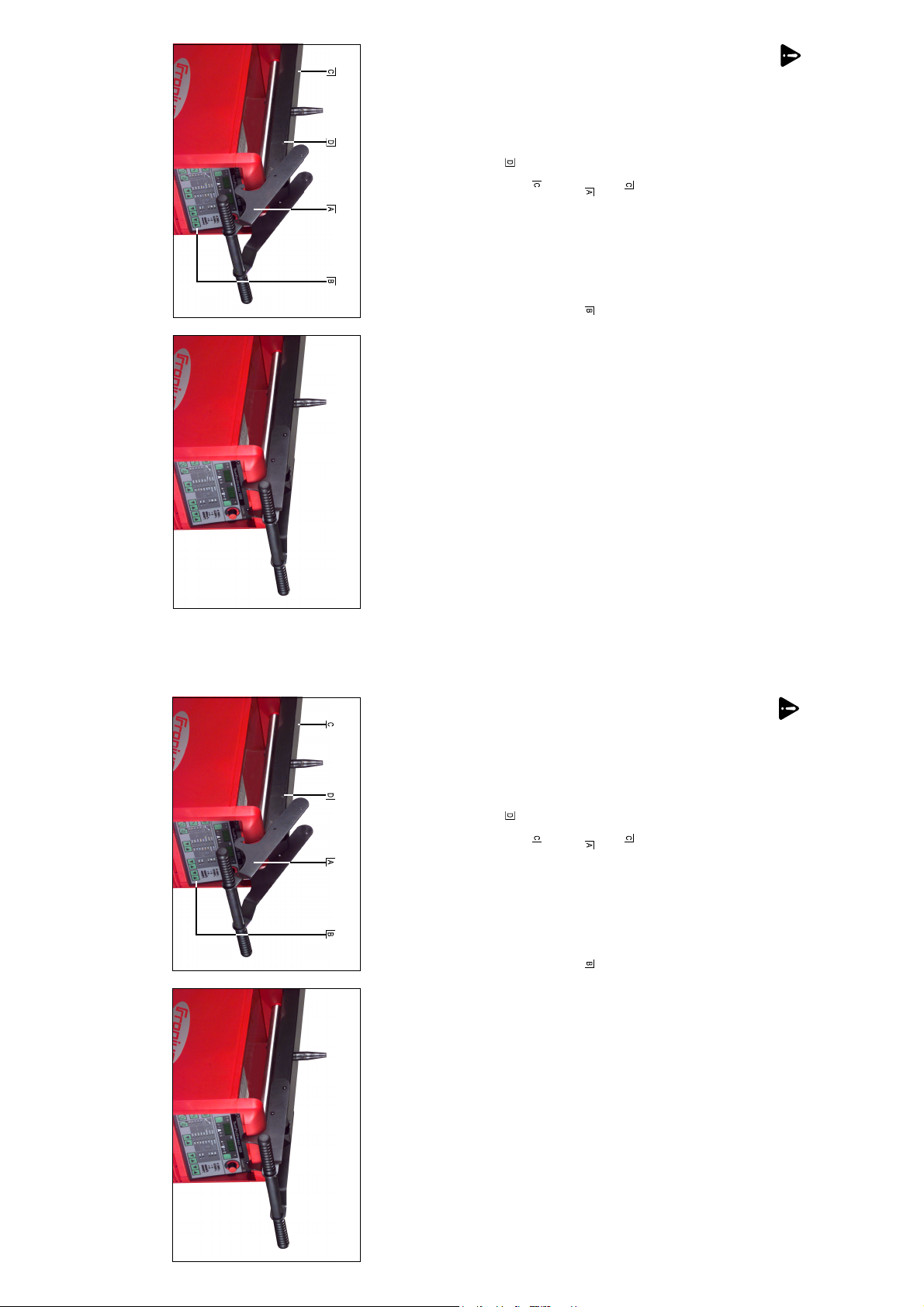
Abb.1 Transportgriff einhängen
Fig.1 Slot the transport handle into place
Abb.2 Transportgriff befestigen
Fig.2 Fasten the transport handle
- Transportgriff mit 4 beiliegenden selbstschneidenden Schrau-
ben an der Drahtvorschubaufnahme befestigen
- Fasten the transport handle onto the wirefeeder fixture, using the
4 tapping screws enclosed with the handle.
Hinweis! Falls die hinteren beiden Löcher an der Drahtvor-
schubaufnahme nicht vorhanden sind, müssen diese mittels 4,2
mm Bohrer gebohrt werden.
mm drill bit.
Deckung kommen
N.B.! If the two rearmost holes on the wirefeeder fixture have
not already been drilled, they must be drilled now, using a 4.2
fixture
- Transportgriff an der Stromquelle am Gehäuserahmen,
- Transportgriff so schwenken, daß die Bohrungen am Transportoberhalb des Bedienpanels, einhängen
griff mit den Bohrungen an der Drahtvorschubaufnahme zur
- Swivel the transport handle so that the boreholes on the trans-
- Slot the transport handle onto the housing of the power source
port handle are exactly over the boreholes on the wirefeeder
, above the operating panel
MONTAGE
Hinweis! Der Transportgriff darf nur in Verbindung mit der
Drahtvorschubaufnahme und nicht als Aufhängevorrichtung
verwendet werden.
nungsanleitung der Stromquelle.
HOW TO FIT
N.B.! The transport handle may only be used in conjunction with the
wirefeeder fixture , and must not be used as a suspension
attachment.
given in the Operating Instructions of the power source.
MONTAGEANLEITUNG TRANSPORTGRIFF
FITTING INSTRUCTIONS FOR TRANSPORT HANDLE
Achtung! Dieser Umbau darf nur von geschultem Fachper-
sonal durchgeführt werden! Vor Öffnen des Gerätes, Netz-
schalter in Stellung „0“ schalten und Netzstecker ziehen!
Beachten Sie die Sicherheitsvorschriften in der Bedie-
Warning! This modification may only be performed by
suitably trained and skilled electricians! Before opening up
the machine, shift the mains switch to the "0" position and
unplug the machine from the mains! Follow the safety rules
Text und Abbildungen entsprechen dem technischen Stand bei Drucklegung. Änderungen vorbehalten.
Text and illustrations technically correct at the time of going to print. Right to effect modifications is reserved.
42,0410,0720 021999
Abb.1 Transportgriff einhängen
Fig.1 Slot the transport handle into place
Abb.2 Transportgriff befestigen
Fig.2 Fasten the transport handle
- Transportgriff mit 4 beiliegenden selbstschneidenden Schrau-
ben an der Drahtvorschubaufnahme befestigen
- Fasten the transport handle onto the wirefeeder fixture, using the
4 tapping screws enclosed with the handle.
Hinweis! Falls die hinteren beiden Löcher an der Drahtvor-
schubaufnahme nicht vorhanden sind, müssen diese mittels 4,2
mm Bohrer gebohrt werden.
mm drill bit.
Deckung kommen
N.B.! If the two rearmost holes on the wirefeeder fixture have
not already been drilled, they must be drilled now, using a 4.2
fixture
- Transportgriff an der Stromquelle am Gehäuserahmen,
- Transportgriff so schwenken, daß die Bohrungen am Transportoberhalb des Bedienpanels, einhängen
griff mit den Bohrungen an der Drahtvorschubaufnahme zur
- Swivel the transport handle so that the boreholes on the trans-
- Slot the transport handle onto the housing of the power source
port handle are exactly over the boreholes on the wirefeeder
, above the operating panel
MONTAGE
Hinweis! Der Transportgriff darf nur in Verbindung mit der
Drahtvorschubaufnahme und nicht als Aufhängevorrichtung
verwendet werden.
nungsanleitung der Stromquelle.
HOW TO FIT
N.B.! The transport handle may only be used in conjunction with the
wirefeeder fixture , and must not be used as a suspension
attachment.
given in the Operating Instructions of the power source.
MONTAGEANLEITUNG TRANSPORTGRIFF
FITTING INSTRUCTIONS FOR TRANSPORT HANDLE
Achtung! Dieser Umbau darf nur von geschultem Fachper-
sonal durchgeführt werden! Vor Öffnen des Gerätes, Netz-
schalter in Stellung „0“ schalten und Netzstecker ziehen!
Beachten Sie die Sicherheitsvorschriften in der Bedie-
Warning! This modification may only be performed by
suitably trained and skilled electricians! Before opening up
the machine, shift the mains switch to the "0" position and
unplug the machine from the mains! Follow the safety rules
Texte et illustrations correspondent à la date d'impression. Modifications réservées.
Fig. 1 Accrocher poignée de transport Fig. 2 Visser poignée de transport
moyen de suspension.
Nota! Si les alésages plus au fond du cadre de montage
dévidoir-fil manquent, les percer au moyen d’un foret 4,2 mm.
- Au moyen des 4 vis autotaradeuses, fixer poignée de transport
au cadre de montage dévidoir-fil.
cadre de montage dévidoir-fil
- Accrocher piognée de transport
- Relever poignée de transport jusqu’à ce que les alesages dans
au-dessous du panneau de commande.
la poignée de transport se superposent aux alésages dans le
MONTAGE
Nota! N’utiliser la poignée de transport qu’en combinaison avec
le cadre de montage dévidoir-fil
INSTRUCTIONS DE MONTAGE POIGNÉE DE TRANSPORT
Attention! Cette modification ne doit être exécutée que par
du personnel expert formé! Avant d’ouvrir l’appareil il faut
mettre l’interrupteur à réseau en position "0" et retirer la
fiche de réseau! Observez les instructions de sécurité dans
le mode d'emploi de la source de courant.
.
. Ne jamais utiliser comme
dans la source de courant ,
Texte et illustrations correspondent à la date d'impression. Modifications réservées.
Fig. 1 Accrocher poignée de transport Fig. 2 Visser poignée de transport
dévidoir-fil manquent, les percer au moyen d’un foret 4,2 mm.
- Au moyen des 4 vis autotaradeuses, fixer poignée de transport
au cadre de montage dévidoir-fil.
Nota! Si les alésages plus au fond du cadre de montage
- Relever poignée de transport jusqu’à ce que les alesages dans
- Accrocher piognée de transport
au-dessous du panneau de commande.
la poignée de transport se superposent aux alésages dans le
cadre de montage dévidoir-fil
.
dans la source de courant ,
MONTAGE
Nota! N’utiliser la poignée de transport qu’en combinaison avec
le cadre de montage dévidoir-fil
moyen de suspension.
. Ne jamais utiliser comme
INSTRUCTIONS DE MONTAGE POIGNÉE DE TRANSPORT
Attention! Cette modification ne doit être exécutée que par
du personnel expert formé! Avant d’ouvrir l’appareil il faut
mettre l’interrupteur à réseau en position "0" et retirer la
fiche de réseau! Observez les instructions de sécurité dans
le mode d'emploi de la source de courant.
 Loading...