

Page 1

/ Battery Charging Systems / Welding Technology / Solar Electronics
DE
EN
TransPocket 3500 Remote
Bedienungsanleitung
Ersatzteilliste
Plasma
Operating Instructions
Spare parts list
Plasma
42,0410,1891 006-24062013
Page 2

0
Page 3

Sehr geehrter Leser
Einleitung Wir danken Ihnen für Ihr entgegengebrachtes Vertrauen und gratulieren Ihnen zu Ihrem
technisch hochwertigen Fronius Produkt. Die vorliegende Anleitung hilft Ihnen, sich mit
diesem vertraut zu machen. Indem Sie die Anleitung sorgfältig lesen, lernen Sie die vielfältigen Möglichkeiten Ihres Fronius-Produktes kennen. Nur so können Sie seine Vorteile
bestmöglich nutzen.
Bitte beachten Sie auch die Sicherheitsvorschriften und sorgen Sie so für mehr Sicherheit
am Einsatzort des Produktes. Sorgfältiger Umgang mit Ihrem Produkt unterstützt dessen
langlebige Qualität und Zuverlässigkeit. Das sind wesentliche Voraussetzungen für hervorragende Ergebnisse.
DE
1
Page 4

2
Page 5

Inhaltsverzeichnis
Sicherheitsvorschriften............................................................................................................................... 5
Erklärung Sicherheitshinweise.............................................................................................................. 5
Allgemeines .......................................................................................................................................... 5
Bestimmungsgemäße Verwendung...................................................................................................... 6
Umgebungsbedingungen...................................................................................................................... 6
Verpflichtungen des Betreibers............................................................................................................. 6
Verpflichtungen des Personals ............................................................................................................. 7
Netzanschluss....................................................................................................................................... 7
Selbst- und Personenschutz ................................................................................................................. 7
Angaben zu Geräuschemissions-Werten .............................................................................................7
Gefahr durch schädliche Gase und Dämpfe.........................................................................................7
Gefahren durch Netz- und Arbeitsstrom ............................................................................................... 8
EMV Geräte-Klassifizierungen.............................................................................................................. 9
EMV-Maßnahmen................................................................................................................................. 9
EMF-Maßnahmen................................................................................................................................. 10
Sicherheitsmaßnahmen am Aufstellort und beim Transport................................................................. 10
Sicherheitsmaßnahmen im Normalbetrieb............................................................................................ 10
Wartung und Instandsetzung ................................................................................................................ 11
Sicherheitstechnische Überprüfung ...................................................................................................... 11
Entsorgung............................................................................................................................................ 12
Sicherheitskennzeichnung .................................................................................................................... 12
Datensicherheit..................................................................................................................................... 12
Urheberrecht ......................................................................................................................................... 12
Allgemeine Informationen .......................................................................................................................... 13
Allgemeines .......................................................................................................................................... 13
Lieferumfang......................................................................................................................................... 13
Prinzip................................................................................................................................................... 13
Gerätekonzept ...................................................................................................................................... 13
Bestimmungsgemäße Verwendung...................................................................................................... 13
Warnhinweise am Gerät ....................................................................................................................... 14
Bedienelemente und Anschlüsse............................................................................................................... 15
Sicherheit.............................................................................................................................................. 15
Bedienelemente und Anschlüsse.......................................................................................................... 15
Vor der Inbetriebnahme ............................................................................................................................. 16
Sicherheit.............................................................................................................................................. 16
Aufstellbestimmungen........................................................................................................................... 16
Netzanschluss....................................................................................................................................... 16
Generatorbetrieb................................................................................................................................... 16
Netzspannung einstellen............................................................................................................................ 17
Allgemein .............................................................................................................................................. 17
Netzspannung einstellen....................................................................................................................... 17
Interface Rob TSt....................................................................................................................................... 18
Sicherheit.............................................................................................................................................. 18
Lieferumfang......................................................................................................................................... 18
Gerätekonzept ...................................................................................................................................... 18
Übersicht............................................................................................................................................... 19
Digitale Eingangssignale (Signale vom Roboter)....................................................................................... 20
Kenngrößen .......................................................................................................................................... 20
Schweißen Ein...................................................................................................................................... 20
Analoge Eingangssignale (Signale vom Roboter) ..................................................................................... 21
Allgemeines .......................................................................................................................................... 21
Sollwert Schweißstrom ......................................................................................................................... 21
Digitale Ausgangssignale (Signale zum Roboter)...................................................................................... 22
Allgemeines .......................................................................................................................................... 22
Stromquelle bereit................................................................................................................................. 22
Prozess aktiv......................................................................................................................................... 22
Stromfluss............................................................................................................................................. 22
Analoge Ausgangssignale (Signale zum Roboter) .................................................................................... 23
Allgemeines .......................................................................................................................................... 23
Istwert Schweißspannung..................................................................................................................... 23
DE
3
Page 6

Istwert Schweißstrom............................................................................................................................ 23
Anschluss-Spezifikationen ......................................................................................................................... 24
Beschaltung der Ein- und Ausgänge .................................................................................................... 24
Anwendungsbeispiel ............................................................................................................................. 25
Interface für Feldbus-Systeme................................................................................................................... 26
Sicherheit.............................................................................................................................................. 26
Lieferumfang Interface Profibus............................................................................................................ 26
Gerätekonzept Profibus ........................................................................................................................ 26
Übersicht............................................................................................................................................... 26
Ein- und Ausgangssignale für Feldbus-Systeme ....................................................................................... 27
Eingangssignale (vom Roboter zur Stromquelle) ................................................................................. 27
Ausgangssignale (von der Stromquelle zum Roboter) ......................................................................... 27
Signalbeschreibungen Feldbus-Systeme .................................................................................................. 29
Signalbeschreibung Eingangssignale (vom Roboter zur Stromquelle)................................................. 29
Signalbeschreibung Ausgangssignale (von der Stromquelle zum Roboter)......................................... 29
Fehlerdiagnose, Fehlerbehebung .............................................................................................................. 31
Allgemeines .......................................................................................................................................... 31
Sicherheit.............................................................................................................................................. 31
Fehlerdiagnose ..................................................................................................................................... 31
Status Anzeigen.................................................................................................................................... 32
Pflege, Wartung und Entsorgung............................................................................................................... 35
Sicherheit.............................................................................................................................................. 35
Allgemeines .......................................................................................................................................... 35
Bei jeder Inbetriebnahme...................................................................................................................... 35
alle 2 Monate ........................................................................................................................................ 35
Alle 6 Monate........................................................................................................................................ 35
Entsorgung............................................................................................................................................ 35
Technische Daten ...................................................................................................................................... 36
TP 3500 CC Remote............................................................................................................................. 36
Interface ROB TSt................................................................................................................................. 36
Appendix 73
Spare parts list: TransPocket 3500 CC Remote ........................................................................................ 74
Circuit diagram: TransPocket 3500 CC Remote ........................................................................................ 76
4
Page 7

Sicherheitsvorschriften
DE
Erklärung Sicherheitshinweise
Allgemeines
GEFAHR! Bezeichnet eine unmittelbar drohende Gefahr. Wenn sie nicht gemie-
den wird, sind Tod oder schwerste Verletzungen die Folge.
WARNUNG! Bezeichnet eine möglicherweise gefährliche Situation. Wenn sie
nicht gemieden wird, können Tod und schwerste Verletzungen die Folge sein.
VORSICHT! Bezeichnet eine möglicherweise schädliche Situation. Wenn sie
nicht gemieden wird, können leichte oder geringfügige Verletzungen sowie Sachschäden die Folge sein.
HINWEIS! Bezeichnet die Gefahr beeinträchtigter Arbeitsergebnisse und möglicher Schäden an der Ausrüstung.
WICHTIG! Bezeichnet Anwendungstipps und andere besonders nützliche Informationen.
Es ist kein Signalwort für eine schädliche oder gefährliche Situation.
Wenn Sie eines der im Kapitel „Sicherheitsvorschriften“ abgebildeten Symbole sehen, ist
erhöhte Achtsamkeit erforderlich.
Das Gerät ist nach dem Stand der Technik und den anerkannten sicherheitstechnischen Regeln gefertigt. Dennoch drohen bei Fehlbedienung oder Missbrauch Gefahr für
- Leib und Leben des Bedieners oder Dritte,
- das Gerät und andere Sachwerte des Betreibers,
- die effiziente Arbeit mit dem Gerät.
Alle Personen, die mit der Inbetriebnahme, Bedienung, Wartung und Instand-
haltung des Gerätes zu tun haben, müssen
- entsprechend qualifiziert sein,
- Kenntnisse vom Schweißen haben und
- diese Bedienungsanleitung vollständig lesen und genau befolgen.
Die Bedienungsanleitung ist ständig am Einsatzort des Gerätes aufzubewah-
ren. Ergänzend zur Bedienungsanleitung sind die allgemein gültigen sowie
die örtlichen Regeln zu Unfallverhütung und Umweltschutz zu beachten.
Alle Sicherheits- und Gefahrenhinweise am Gerät
- in lesbarem Zustand halten
- nicht beschädigen
- nicht entfernen
- nicht abdecken, überkleben oder übermalen.
Die Positionen der Sicherheits- und Gefahrenhinweise am Gerät, entnehmen
Sie dem Kapitel „Allgemeines“ der Bedienungsanleitung Ihres Gerätes.
Störungen, die die Sicherheit beeinträchtigen können, vor dem Einschalten
des Gerätes beseitigen.
Es geht um Ihre Sicherheit!
5
Page 8

Bestimmungsgemäße Verwendung
Das Gerät ist ausschließlich für Arbeiten im Sinne der bestimmungsgemäßen
Verwendung zu benutzen.
Das Gerät ist ausschließlich für die am Leistungsschild angegebenen
Schweißverfahren bestimmt.
Eine andere oder darüber hinaus gehende Benutzung gilt als nicht bestimmungsgemäß. Für hieraus entstandene Schäden haftet der Hersteller nicht.
Zur bestimmungsgemäßen Verwendung gehört auch
- das vollständige Lesen und Befolgen aller Hinweise aus der Bedienungsanleitung
- das vollständige Lesen und Befolgen aller Sicherheits- und Gefahrenhinweise
- die Einhaltung der Inspektions- und Wartungsarbeiten.
Das Gerät niemals für folgende Anwendungen verwenden:
- Auftauen von Rohren
- Laden von Batterien/Akkumulatoren
- Start von Motoren
Das Gerät ist für den Betrieb in Industrie und Gewerbe ausgelegt. Für Schäden, die auf den Einsatz im Wohnbereich zurückzuführen sind, haftet der Hersteller nicht.
Für mangelhafte oder fehlerhafte Arbeitsergebnisse übernimmt der Hersteller
ebenfalls keine Haftung.
Umgebungsbedingungen
Verpflichtungen
des Betreibers
Betrieb oder Lagerung des Gerätes außerhalb des angegebenen Bereiches
gilt als nicht bestimmungsgemäß. Für hieraus entstandene Schäden haftet
der Hersteller nicht.
Temperaturbereich der Umgebungsluft:
- beim Betrieb: -10 °C bis + 40 °C (14 °F bis 104 °F)
- bei Transport und Lagerung: -20 °C bis +55 °C (-4 °F bis 131 °F)
Relative Luftfeuchtigkeit:
- bis 50 % bei 40 °C (104 °F)
- bis 90 % bei 20 °C (68 °F)
Umgebungsluft: frei von Staub, Säuren, korrosiven Gasen oder Substanzen,
usw.
Höhenlage über dem Meeresspiegel: bis 2000 m (6561 ft. 8.16 in.)
Der Betreiber verpflichtet sich, nur Personen am Gerät arbeiten zu lassen, die
- mit den grundlegenden Vorschriften über Arbeitssicherheit und Unfallverhütung vertraut und in die Handhabung des Gerätes eingewiesen sind
- diese Bedienungsanleitung, insbesondere das Kapitel „Sicherheitsvorschriften“ gelesen, verstanden und dies durch ihre Unterschrift bestätigt
haben
- entsprechend den Anforderungen an die Arbeitsergebnisse ausgebildet
sind.
Das sicherheitsbewusste Arbeiten des Personals ist in regelmäßigen Abständen zu überprüfen.
6
Page 9

Verpflichtungen
des Personals
Alle Personen, die mit Arbeiten am Gerät beauftragt sind, verpflichten sich, vor
Arbeitsbeginn
- die grundlegenden Vorschriften über Arbeitssicherheit und Unfallverhütung zu befolgen
- diese Bedienungsanleitung, insbesondere das Kapitel „Sicherheitsvorschriften“ zu lesen und durch ihre Unterschrift zu bestätigen, dass sie diese verstanden haben und befolgen werden.
Vor Verlassen des Arbeitsplatzes sicherstellen, dass auch in Abwesenheit keine Personen- oder Sachschäden auftreten können.
DE
Netzanschluss
Selbst- und Personenschutz
Geräte mit hoher Leistung können auf Grund ihrer Stromaufnahme die Energiequalität des Netzes beeinflussen.
Das kann einige Gerätetypen betreffen in Form von:
- Anschluss-Beschränkungen
- Anforderungen hinsichtlich maximal zulässiger Netzimpedanz
*)
- Anforderungen hinsichtlich minimal erforderlicher Kurzschluss-Leistung
*)
jeweils an der Schnittstelle zum öffentlichen Netz
siehe Technische Daten
In diesem Fall muss sich der Betreiber oder Anwender des Gerätes versi-
chern, ob das Gerät angeschlossen werden darf, gegebenenfalls durch Rücksprache mit dem Energieversorgungs-Unternehmen.
Personen, vor allem Kinder, während des Betriebes vom Gerät und vom Arbeitsbereich fernhalten. Befinden sich dennoch Personen in der Nähe
- diese über alle Gefahren (gesundheitsschädliche Säuren und Gase, Gefährdung durch Netz- und Ladestrom, ...) unterrichten,
- geeignete Schutzmittel zur Verfügung stellen.
Vor Verlassen des Arbeitsbereiches sicherstellen, dass auch in Abwesenheit
keine Personen- oder Sachschäden auftreten können.
*)
Angaben zu GeräuschemissionsWerten
Gefahr durch
schädliche Gase
und Dämpfe
Das Gerät erzeugt einen maximalen Schallleistungspegel <80dB(A) (ref.
1pW) bei Leerlauf sowie in der Kühlungsphase nach Betrieb entsprechend
dem maximal zulässigem Arbeitspunkt bei Normlast gemäß EN 60974-1.
Ein arbeitsplatzbezogener Emissionswert kann beim Schweißen (und Schneiden) nicht angegeben werden, da dieser verfahrens- und umgebungsbedingt
ist. Er ist abhängig von den verschiedensten Parametern wie z.B. Schweißverfahren (MIG/MAG-, WIG-Schweißen), der angewählten Stromart (Gleichstrom, Wechselstrom), dem Leistungsbereich, der Art des Schweißgutes,
dem Resonanzverhalten des Werkstückes, der Arbeitsplatzumgebung u.a.m.
Beim Schweißen entstehender Rauch enthält gesundheitsschädliche Gase
und Dämpfe.
Schweißrauch enthält Substanzen, die unter Umständen Geburtsschäden
und Krebs verursachen können.
Kopf von entstehendem Schweißrauch und Gasen fernhalten.
7
Page 10

Entstehenden Rauch sowie schädliche Gase
- nicht einatmen
- durch geeignete Mittel aus dem Arbeitsbereich absaugen.
Für ausreichend Frischluft-Zufuhr sorgen.
Bei nicht ausreichender Belüftung Atemschutz-Maske mit Luftzufuhr verwen-
den.
Wird nicht geschweißt, das Ventil der Schutzgas-Flasche oder Hauptgasver-
sorgung schließen.
Besteht Unklarheit darüber, ob die Absaugleistung ausreicht, die gemessenen
Schadstoff-Emissionswerte mit den zulässigen Grenzwerten vergleichen.
Folgende Komponenten sind unter anderem für den Grad der Schädlichkeit
des Schweißrauches verantwortlich:
- Für das Werkstück eingesetzte Metalle
- Elektroden
- Beschichtungen
- Reiniger, Entfetter und dergleichen
Daher die entsprechenden Materialsicherheits-Datenblätter und Herstellerangaben zu den aufgezählten Komponenten berücksichtigen.
Entzündliche Dämpfe (z.B. Lösungsmittel-Dämpfe) vom Strahlungsbereich
des Lichtbogens fernhalten.
Gefahren durch
Netz- und Arbeitsstrom
Ein elektrischer Schlag ist lebensgefährlich und kann tödlich sein.
Spannungsführende Teile innerhalb und außerhalb des Gerätes nicht berühren.
Sämtliche Kabel und Leitungen müssen fest, unbeschädigt, isoliert und ausreichend dimensioniert sein. Lose Verbindungen, angeschmorte, beschädigte
oder unterdimensionierte Kabel und Leitungen sofort erneuern.
Das Gerät nur in Betrieb nehmen wenn es ausgangsseitig ordnungsgemäß
angeschlossen ist.
Das Gerät nur an einem Netz mit Schutzleiter betreiben. Wird das Gerät an
einem Netz ohne Schutzleiter betrieben, gilt dies als grob fahrlässig. Für hieraus entstandene Schäden haftet der Hersteller nicht.
Netz- und Gerätezuleitung regelmäßig von einer Elektro-Fachkraft auf Funktionstüchtigkeit des Schutzleiters überprüfen lassen.
Nicht verwendete Geräte ausschalten.
Vor Arbeiten am Gerät das Gerät abschalten und Netzstecker ziehen.
Das Gerät durch ein deutlich lesbares und verständliches Warnschild gegen
Anstecken des Netzsteckers und Wiedereinschalten sichern.
Nach dem Öffnen des Gerätes:
- alle Bauteile die elektrische Ladungen speichern entladen
- sicherstellen, dass alle Komponenten des Gerätes stromlos sind.
Sind Arbeiten an spannungsführenden Teilen notwendig, eine zweite Person
hinzuziehen, die den Hauptschalter rechtzeitig ausschaltet.
8
Page 11

EMV Geräte-Klassifizierungen
Geräte der Emissionsklasse A:
- sind nur für den Gebrauch in Industriegebieten vorgesehen
- können in anderen Gebieten leitungsgebundene und gestrahlte
Störungen verursachen.
Geräte der Emissionsklasse B:
- erfüllen die Emissionsanforderungen für Wohn- und Industriegebiete. Dies gilt auch für Wohngebiete, in denen die Energieversorgung aus dem öffentlichen Niederspannungsnetz erfolgt.
EMV Geräte-Klassifizierung gemäß Leistungsschild oder technischen Daten.
DE
EMV-Maßnahmen
In besonderen Fällen können trotz Einhaltung der genormten EmissionsGrenzwerte Beeinflussungen für das vorgesehene Anwendungsgebiet auftreten (z.B. wenn empfindliche Geräte am Aufstellungsort sind oder wenn der
Aufstellungsort in der Nähe von Radio- oder Fernsehempfängern ist).
In diesem Fall ist der Betreiber verpflichtet, angemessene Maßnahmen für die
Störungsbehebung zu ergreifen.
Mögliche Probleme und Störfestigkeit von Einrichtungen in der Umgebung gemäß nationalen und internationalen Bestimmungen prüfen und bewerten:
- Sicherheitseinrichtungen
- Netz-, Signal- und Daten-Übertragungsleitungen
- EDV- und Telekommunikations-Einrichtungen
- Einrichtungen zum Messen und Kalibrieren
Unterstützende Maßnahmen zur Vermeidung von EMV-Problemen:
1. Netzversorgung
- Treten elektromagnetische Störungen trotz vorschriftsgemäßem
Netzanschluss auf, zusätzliche Maßnahmen ergreifen (z.B. geeigneten Netzfilter verwenden).
2. Schweißleitungen
- so kurz wie möglich halten
- eng zusammen verlaufen lassen (auch zur Vermeidung von EMFProblemen)
- weit entfernt von anderen Leitungen verlegen
3. Potentialausgleich
4. Erdung des Werkstückes
- Falls erforderlich, Erdverbindung über geeignete Kondensatoren
herstellen.
5. Abschirmung, falls erforderlich
- Andere Einrichtungen in der Umgebung abschirmen
- Gesamte Schweißinstallation abschirmen
9
Page 12

EMF-Maßnahmen
Elektromagnetische Felder können Gesundheitsschäden verursachen, die
noch nicht bekannt sind:
- Auswirkungen auf die Gesundheit benachbarter Personen, z.B. Träger
von Herzschrittmachern und Hörhilfen
- Träger von Herzschrittmachern müssen sich von ihrem Arzt beraten lassen, bevor sie sich in unmittelbarer Nähe des Gerätes und des Schweißprozesses aufhalten
- Abstände zwischen Schweißkabeln und Kopf/Rumpf des Schweißers aus
Sicherheitsgründen so groß wie möglich halten
- Schweißkabel und Schlauchpakete nicht über der Schulter tragen und
nicht um den Körper und Körperteile wickeln
Sicherheitsmaßnahmen am Aufstellort und beim
Transport
Ein umstürzendes Gerät kann Lebensgefahr bedeuten! Das Gerät auf
ebenem, festem Untergrund standsicher aufstellen
- Ein Neigungswinkel von maximal 10° ist zulässig.
In feuer- und explosionsgefährdeten Räumen gelten besondere Vorschriften
- entsprechende nationale und internationale Bestimmungen beachten.
Durch innerbetriebliche Anweisungen und Kontrollen sicherstellen, dass die
Umgebung des Arbeitsplatzes stets sauber und übersichtlich ist.
Das Gerät nur gemäß der am Leistungsschild angegebenen Schutzart aufstellen und betreiben.
Beim Aufstellen des Gerätes einen Rundumabstand von 0,5 m (1 ft. 7.69 in.)
sicherstellen, damit die Kühlluft ungehindert ein- und austreten kann.
Beim Transport des Gerätes dafür Sorge tragen, dass die gültigen nationalen
und regionalen Richtlinien und Unfallverhütungs-Vorschriften eingehalten
werden. Dies gilt speziell für Richtlinien hinsichtlich Gefährdung bei Transport
und Beförderung.
Vor jedem Transport des Gerätes, das Kühlmittel vollständig ablassen, sowie
folgende Komponenten demontieren:
- Drahtvorschub
- Drahtspule
- Schutzgas-Flasche
Vor der Inbetriebnahme, nach dem Transport, unbedingt eine Sichtprüfung
des Gerätes auf Beschädigungen vornehmen. Allfällige Beschädigungen vor
Inbetriebnahme von geschultem Servicepersonal instandsetzen lassen.
Sicherheitsmaßnahmen im Normalbetrieb
10
Das Gerät nur betreiben, wenn alle Sicherheitseinrichtungen voll funktionstüchtig sind. Sind die Sicherheitseinrichtungen nicht voll funktionstüchtig, besteht Gefahr für
- Leib und Leben des Bedieners oder Dritte,
- das Gerät und andere Sachwerte des Betreibers
- die effiziente Arbeit mit dem Gerät.
Nicht voll funktionstüchtige Sicherheitseinrichtungen vor dem Einschalten des
Gerätes instandsetzen.
Sicherheitseinrichtungen niemals umgehen oder außer Betrieb setzen.
Vor Einschalten des Gerätes sicherstellen, dass niemand gefährdet werden
kann.
Das Gerät mindestens einmal pro Woche auf äußerlich erkennbare Schäden
und Funktionstüchtigkeit der Sicherheitseinrichtungen überprüfen.
Page 13

Schutzgas-Flasche immer gut befestigen und bei Krantransport vorher abnehmen.
Nur das Original-Kühlmittel des Herstellers ist auf Grund seiner Eigenschaften
(elektrische Leitfähigkeit, Frostschutz, Werkstoff-Verträglichkeit, Brennbarkeit, ...) für den Einsatz in unseren Geräten geeignet.
Nur geeignetes Original-Kühlmittel des Herstellers verwenden.
Original-Kühlmittel des Herstellers nicht mit anderen Kühlmitteln mischen.
Kommt es bei Verwendung anderer Kühlmittel zu Schäden, haftet der Herstel-
ler hierfür nicht und sämtliche Gewährleistungsansprüche erlöschen.
Das Kühlmittel ist unter bestimmten Voraussetzungen entzündlich. Das Kühl-
mittel nur in geschlossenen Original-Gebinden transportieren und von Zündquellen fernhalten
Ausgedientes Kühlmittel den nationalen und internationalen Vorschriften entsprechend fachgerecht entsorgen. Das Kühlmittel-Sicherheitsdatenblatt erhalten Sie bei Ihrer Service-Stelle oder über die Homepage des Herstellers.
Bei abgekühlter Anlage vor jedem Schweißbeginn den Kühlmittel-Stand prüfen.
DE
Wartung und Instandsetzung
Sicherheitstechnische Überprüfung
Bei fremdbezogenen Teilen ist nicht gewährleistet, dass sie beanspruchungsund sicherheitsgerecht konstruiert und gefertigt sind. Nur Original-Ersatz- und
Verschleißteile verwenden (gilt auch für Normteile).
Ohne Genehmigung des Herstellers keine Veränderungen, Ein- oder Umbauten am Gerät vornehmen.
Bauteile in nicht einwandfreiem Zustand sofort austauschen.
Bei Bestellung genaue Benennung und Sachnummer laut Ersatzteilliste, sowie Seriennummer Ihres Gerätes angeben.
Der Hersteller empfiehlt, mindestens alle 12 Monate eine sicherheitstechnische Überprüfung am Gerät durchführen zu lassen.
Innerhalb desselben Intervalles von 12 Monaten empfiehlt der Hersteller eine
Kalibrierung von Stromquellen.
Eine sicherheitstechnische Überprüfung durch eine geprüfte Elektro-Fachkraft wird empfohlen
- nach Veränderung
- nach Ein- oder Umbauten
- nach Reparatur, Pflege und Wartung
- mindestens alle zwölf Monate.
Für die sicherheitstechnische Überprüfung die entsprechenden nationalen
und internationalen Normen und Richtlinien befolgen.
Nähere Informationen für die sicherheitstechnische Überprüfung und Kalibrierung erhalten Sie bei Ihrer Service-Stelle. Diese stellt Ihnen auf Wunsch die
erforderlichen Unterlagen zur Verfügung.
11
Page 14

Entsorgung
Werfen Sie dieses Gerät nicht in den Hausmüll! Gemäß Europäischer Richtlinie 2002/96/EG über Elektro- und Elektronik-Altgeräte und Umsetzung in nationales Recht, müssen verbrauchte Elektrowerkzeuge getrennt gesammelt
und einer umweltgerechten Wiederverwertung zugeführt werden. Stellen Sie
sicher, dass Sie Ihr gebrauchtes Gerät bei Ihrem Händler zurückgeben oder
holen Sie Informationen über ein lokales, autorisiertes Sammel- und Entsorgungssystem ein. Ein Ignorieren dieser EU-Direktive kann zu potentiellen
Auswirkungen auf die Umwelt und Ihre Gesundheit führen!
Sicherheitskennzeichnung
Datensicherheit
Urheberrecht
Geräte mit CE-Kennzeichnung erfüllen die grundlegenden Anforderungen der
Niederspannungs- und Elektromagnetischen Verträglichkeits-Richtlinie (z.B.
relevante Produktnormen der Normenreihe EN 60 974).
Mit dem CSA-Prüfzeichen gekennzeichnete Geräte erfüllen die Anforderungen der relevanten Normen für Kanada und USA.
Für die Datensicherung von Änderungen gegenüber den Werkseinstellungen
ist der Anwender verantwortlich. Im Falle gelöschter persönlicher Einstellungen haftet der Hersteller nicht.
Das Urheberrecht an dieser Bedienungsanleitung verbleibt beim Hersteller.
Text und Abbildungen entsprechen dem technischen Stand bei Drucklegung.
Änderungen vorbehalten. Der Inhalt der Bedienungsanleitung begründet keinerlei Ansprüche seitens des Käufers. Für Verbesserungsvorschläge und Hinweise auf Fehler in der Bedienungsanleitung sind wir dankbar.
12
Page 15

Allgemeine Informationen
Allgemeines Zum Betreiben der Stromquelle TP 3500 Remote ist eines der folgenden Interfaces unbe-
dingt erforderlich:
- Roboter-Interface ROB TSt
- Roboter-Interface Profibus
Das Betreiben der Stromquelle TP 3500 Remote ohne eines der angegebenen Interfaces
gilt als nicht bestimmungsgemäß und ist daher nicht zulässig.
Die Interfaces sind nicht im Lieferumfang der Stromquelle enthalten und separat zu bestellen.
Im Servicefall kann die Stromquelle TP 3500 Remote auch mit der Fernbedienung
TR 3000 betrieben werden.
DE
Lieferumfang
(1)
(2)
Prinzip Die Stromquelle arbeitet nach dem Prinzip eines Resonanzinverters und bietet daher eine
Reihe von Vorteilen:
- Intelligente Regelung für stabilen Schweißstrom
- Geringes Gewicht und kleinste Abmessungen
- Hohe Schaltfrequenzen bei optimalem Wirkungsgrad
(1) Stromquelle TP 3500 Remote
(2) Isolationskappen
Gerätekonzept Die Stromquelle TP 3500 Remote ist klein, kompakt und robust. Ein pulverbeschichtetes
Blechgehäuse mit Edelstahlkufen, durch Kunststoffrahmen geschützt angebrachte Bedienelemente und Anschlussbuchsen mit Innengewinde sorgen dafür, das die Stromquelle selbst unter harten Einsatzbedingungen zuverlässig funktioniert.
Der Tragegriff ermöglicht einen komfortablen Transport.
Bestimmungsgemäße Verwendung
Die Stromquelle ist ausschließlich bestimmt
- zur Stromversorgung für Plasmaprozesse
- zur Verwendung zusammen mit dem Roboter-Interface ROB TSt
13
Page 16

Eine andere oder darüber hinausgehende Benutzung gilt als nicht bestimmungsgemäß.
(1)
Für hieraus entstehende Schäden haftet der Hersteller nicht.
Zur bestimmungsgemäßen Verwendung gehört auch
- das Beachten aller Hinweise aus der Bedienungsanleitung
- die Einhaltung der Inspektions- und Wartungsarbeiten
Warnhinweise am
Gerät
An der Stromquelle befinden sich Warnhinweise und Sicherheitssymbole. Diese Warnhinweise und Sicherheitssymbole dürfen weder entfernt noch übermalt werden. Die Hinweise
und Symbole warnen vor Fehlbedienung, woraus schwerwiegende Personen- und Sachschäden resultieren können.
(1) SP = Spezial Programm
Werte für den zulässigen Plasma Arbeitspunkt
Sicherheitssymbole am Leistungsschild
Schweißen ist gefährlich. Folgende
Grundvoraussetzungen müssen erfüllt
sein:
- Ausreichende Qualifikation für das
Schweißen
- Geeignete Schutzausrüstung
- Fernhalten unbeteiligter Personen
Beschriebene Funktionen erst anwenden, wenn folgende Dokumente vollständig gelesen und verstanden
wurden:
- diese Bedienungsanleitung
- sämtliche Bedienungsanleitungen
der Systemkomponenten, insbesondere Sicherheitsvorschriften
14
Page 17

Bedienelemente und Anschlüsse
(1)
(2)
(4)
(5)
(6)
(7)
(8)
(9)
(3)
DE
Sicherheit
Bedienelemente
und Anschlüsse
WARNUNG! Fehlbedienung kann schwerwiegende Personen- und Sachschä-
den verursachen. Beschriebene Funktionen erst anwenden, wenn folgende Dokumente vollständig gelesen und verstanden wurden:
- diese Bedienungsanleitung
- sämtliche Bedienungsanleitungen der Systemkomponenten, insbesondere
Sicherheitsvorschriften
Pos Bezeichnung / Funktion
(1) Netzschalter
(2) Netzkabel
(3) Staubfilter ... im Ansaugbereich des Lüfters
- verhindert die Verschmutzung des Gehäuseinneren bei starkem Staubanfall
(4) Anzeige Übertemperatur
- leuchtet wenn das Gerät thermisch überlastet ist
(5) Anzeige Interface
- leuchtet grün wenn die Stromquelle bereit ist
- blinkt rot wenn ein Fehler vorliegt
(6) (+) Strombuchse
- mit M12 Innengewinde
(7) Anschluss LocalNet
- zum Anschließen des Interface ROB TSt
(8) Status Anzeigen
- die Status Anzeigen geben Aufschluss über die Art eines Fehlers wenn die
Anzeige Interface rot blinkt
(9) (+) Strombuchse
- mit M12 Innengewinde
15
Page 18

Vor der Inbetriebnahme
Sicherheit
Aufstellbestimmungen
WARNUNG! Fehlbedienung kann schwerwiegende Personen- und Sachschä-
den verursachen. Beschriebene Funktionen erst anwenden, wenn folgende Dokumente vollständig gelesen und verstanden wurden:
- diese Bedienungsanleitung
- sämtliche Bedienungsanleitungen der Systemkomponenten, insbesondere
Sicherheitsvorschriften
WARNUNG! Umstürzende oder herabfallende Geräte können Lebensgefahr bedeuten. Geräte auf ebenem und festem Untergrund standsicher aufstellen.
Das Gerät ist nach Schutzart IP23 geprüft, das bedeutet:
- Schutz gegen Eindringen fester Fremdkörper größer Ø 12 mm (0.49 in.)
- Schutz gegen Sprühwasser bis zu einem Winkel von 60° zur Senkrechten
Kühlluft
Die Anlage muss so aufgestellt werden, dass die Kühlluft ungehindert durch die Luftschlitze der Vorder- und Rückseite strömen kann.
Staub
Es ist darauf zu achten, dass anfallender metallischer Staub, nicht direkt vom Lüfter in die
Anlage gesaugt wird. (zum Beispiel bei Schmirgelarbeiten)
Betrieb im Freien
Das Gerät kann gemäß Schutzart IP23 im Freien aufgestellt und betrieben werden. Unmittelbare Nässeeinwirkung (z.B. durch Regen) ist zu vermeiden.
Netzanschluss Das Gerät ist für die am Leistungschild angegebene Netzspannung ausgelegt. Die erfor-
derliche Absicherung der Netzzuleitung finden Sie im Abschnitt „Technische Daten“. Sind
Netzkabel oder Netzstecker bei Ihrer Geräteausführung nicht angebracht, Netzkabel oder
Netzstecker entsprechend den nationalen Normen montieren.
HINWEIS! Nicht ausreichend dimensionierte Elektroinstallation kann zu schwerwiegenden Sachschäden führen. Die Netzzuteilung sowie deren Absicherung
sind entsprechend der vorhandenen Stromversorgung auszulegen. Es gelten die
Technischen Daten auf dem Leistungsschild.
Generatorbetrieb Die Stromquelle ist generatortauglich, wenn die maximal abgegebene Scheinleistung des
Generators mindestens 22 kVA beträgt.
HINWEIS! Die abgegebene Spannung des Generators darf den Bereich der
Netzspannungs-Toleranz keinesfalls unter- oder überschreiten. Die Angabe der
Netzspannungs-Toleranz erfolgt im Abschnitt „Technische Daten“.
16
Page 19

Netzspannung einstellen
1
200V - 240V
2
2
1
3
Allgemein MVm-Geräte (MultiVoltage manuell) sind sowohl für den Betrieb an einer Netzspannung
von 380 - 460V, als auch an einer Netzspannung von 200 - 240V geeignet.
HINWEIS! Serienmäßig werden die Geräte mit der Einstellung 380 - 460V ausgeliefert. Das Umstellen des Netzspannungsbereiches muss manuell erfolgen.
DE
Netzspannung
einstellen
WARNUNG! Ein elektrischer Schlag kann tödlich sein. Vor Öffnen des Gerätes
- Netzschalter in Stellung - O - schalten
- Gerät vom Netz trennen
- gegen Wiedereinschalten sichern
- mit Hilfe eines geeigneten Messgerätes sicherstellen, dass elektrisch geladene Bauteile (z.B. Kondensatoren) entladen sind
1
1
1
3
2
380V - 460V
2
3
1
2
4
17
Page 20

Interface Rob TSt
Sicherheit
Lieferumfang
WARNUNG! Fehlbedienung kann schwerwiegende Personen- und Sachschä-
den verursachen. Beschriebene Funktionen erst anwenden, wenn folgende Dokumente vollständig gelesen und verstanden wurden:
- diese Bedienungsanleitung
- sämtliche Bedienungsanleitungen der Systemkomponenten, insbesondere
Sicherheitsvorschriften
(1)
(2)
(1) Interface ROB TSt
(2) Kabelbaum LocalNet (1 m)
Gerätekonzept Das Interface ROB TSt ist ein Automaten- und Roboter-Interfaces mit analogen und digi-
talen Ein- und Ausgängen. Es ist für den Einbau in einen Automaten- oder Roboterschaltschrank ausgelegt (auch Anbau möglich).
Merkmale:
- Verbindung zur Stromquelle über standardisierte LocalNet-Schnittstelle
- Kein Umbau der Stromquelle notwendig
- Analoge Ein- und Ausgänge für die Übertragung von Prozessgrößen
- Dadurch Unabhängigkeit von Bit-Breite der Datenverarbeitung in der vorhandenen
Robotersteuerung
- Einfacher Austausch der Stromquelle
- Einfache Steckverbindungen
- Geringer Verdrahtungsaufwand
- Montage erfolgt mittels Hutschienenaufnahme
- Hohe Störsicherheit bei der Datenübertragung
- Die Ansteuerung der Stromquelle erfolgt über analoge Sollwerte
(0-10 V für den Schweißstrom)
Der Anschluss des Roboter-Interfaces erfolgt über ein 10-poliges Verbindungskabel am
Anschluss LocalNet der Stromquelle.
Das Verbindungskabel ist nicht im Lieferumfang enthalten und separat zu bestellen.
Mit dem Roboter-Interface wird ein 1 m langer Kabelbaum LocalNet sowie eine 10-polige
Anschlussbuchse mitgeliefert. Die 10-polige Anschlussbuchse dient als Durchgangsstück
durch die Schaltschrankwand.
18
Page 21

Übersicht “Interface ROB TSt“ umfasst folgende Abschnitte:
- Digitale Eingangssignale (Signale vom Roboter)
- Analoge Eingangssignale (Signale vom Roboter)
- Digitale Ausgangssignale (Signale zum Roboter)
- Analoge Ausgangssignale (Signale zum Roboter)
- Anschluss-Spezifikationen
DE
19
Page 22

Digitale Eingangssignale (Signale vom Roboter)
Kenngrößen Signalpegel:
- LOW (0) .. 0 - 2,5 V
- HIGH (1) .. 18 - 30 V
Bezugspotential: GND = X7/2 oder X12/2
HINWEIS! Sämtliche Signalzustände beziehen sich auf den Interface-Eingang,
nicht auf die Robotersteuerung.
Schweißen Ein
Stecker X2/4 HIGH
Das Signal “Schweißen ein” startet den Schweißprozess. Solange das Signal
“Schweißen Ein“ gesetzt ist, bleibt der Schweißprozess aktiv.
Ausnahme:
- Das digitale Ausgangssignal “Stromquelle bereit“ fehlt
20
Page 23

Analoge Eingangssignale (Signale vom Roboter)
Allgemeines Die analogen Differenzverstärker-Eingänge am Roboter-Interface gewährleisten eine gal-
vanische Trennung des Roboter-Interfaces von den analogen Ausgängen der Robotersteuerung. Jeder Eingang am Roboter-Interface verfügt über ein eigenes negatives
Potential.
HINWEIS! Besitzt die Robotersteuerung nur einen gemeinsamen Anschluss
“GND“ für ihre analogen Ausgangssignale, müssen die negativen Potentiale der
Eingänge am Roboter-Interface miteinander verbunden werden!
Die nachfolgend beschriebenen analogen Eingänge sind bei Spannungen von 0-10 V aktiv.
DE
Sollwert Schweißstrom
Stecker X2/1 Analog in + 0 bis + 10 V
Stecker X2/8 Analog in - (Minus)
Der Sollwert Schweißstrom wird mit einer Spannung von 0 - 10 V vorgegeben.
- 1 V am analogen Eingang entspricht 100 A Schweißstrom
- Daraus ergibt sich für den Sollwert Schweißstrom ein Bereich von 0 - 1000 A
21
Page 24

Digitale Ausgangssignale (Signale zum Roboter)
Allgemeines
Stromquelle bereit
HINWEIS! Ist die Verbindung zwischen Stromquelle und Interface ROB TSt un-
terbrochen, werden alle digitalen / analogen Ausgangssignale am Roboter-Interface auf “0” gesetzt.
Im Interface ROB TSt ist die Versorgungsspannung Stromquelle (24 V SECONDARY) verfügbar.
24 V SECONDARY ist mit galvanischer Trennung zum LocalNet ausgeführt. Eine Schutzbeschaltung begrenzt unzulässige Spannungspegel auf 100 V.
Am Stecker X14/1 auswählen, welche Spannung an die digitalen Ausgänge des Interface
ROB TSt geschaltet wird:
- Externe Spannung Robotersteuerung (24 V):
An Pin X14/1 die externe Spannung der digitalen Ausgangskarte der Robotersteuerung (SPS) anlegen
- Versorgungsspannung Stromquelle (24 V SECONDARY):
Einen Bügel zwischen X14/1 und X14/7 anbringen
Stecker X2/14 Signal 24 V
Stecker X7/2 oder X12/2 oder X5/10 GND
Das Signal “Stromquelle bereit” bleibt gesetzt, solange die Stromquelle arbeitsbereit ist.
Das Signal “Stromquelle bereit” liegt nicht mehr an, sobald an der Stromquelle eine Fehlermeldung auftritt.
Prozess aktiv Das Signal “Prozess aktiv” bleibt gesetzt, solange die Stromquelle aktiv ist.
Das heißt es liegt eine Leerlauf-Spannung oder ein Schweißstrom an den Strombuchsen
an.
Stromfluss Das Signal “Stromfluss” wird gesetzt, wenn der Schweißstrom 10 A oder höher ist.
22
Page 25

Analoge Ausgangssignale (Signale zum Roboter)
DE
Allgemeines
Istwert Schweißspannung
Istwert Schweißstrom
HINWEIS! Ist die Verbindung zwischen Stromquelle und Interface ROB TSt un-
terbrochen, werden alle digitalen / analogen Ausgangssignale am Roboter-Interface auf “0” gesetzt.
Die analogen Ausgänge am Roboter-Interface stehen für die Einrichtung des Roboters sowie für Anzeige- und Dokumentation von Prozessparametern zur Verfügung.
Stecker X5/4 Analog out + 0 bis +10 V
Stecker X5/11 Analog out - (Minus)
Der Istwert Schweißspannung wird mit einer Spannung von 0 - 10 V an den analogen Ausgang übertragen.
- 1 V am analogen Ausgang entspricht 10 V Schweißspannung
- Daraus ergibt sich für den Istwert Schweißspannung ein Bereich von 0 - 100 V
Stecker X2/3 Analog out + 0 bis +10 V
Stecker X2/10 Analog out - (Minus)
Der Istwert Schweißstrom wird mit einer Spannung von 0 - 10 V an den analogen Ausgang
übertragen.
- 1 V am analogen Ausgang entspricht 100 A Schweißstrom
- Daraus ergibt sich für den Istwert Schweißstrom ein Bereich von 0 - 1000 A
23
Page 26

Anschluss-Spezifikationen
Beschaltung der
Ein- und Ausgänge
Beschaltung des digitalen Ausganges
Beschaltung des digitalen Einganges
Beschaltung des analogen Ausganges
24
Beschaltung des analogen Einganges
Page 27

Anwendungsbei-
CURRENT FLOW (DIG. OUT)
WELDING START (DIG. IN)
X2/4
X5/11
X5/4
X2/10
X2/3
X14/1
X5/10
X4/7
X2/14
X8/10
X2/8
X2/1
X2/12
+24 V SECONDARY
GND SECONDARY
SUPPLY VOLTAGE
spiel
DE
25
Page 28

Interface für Feldbus-Systeme
Sicherheit
Lieferumfang
Interface Profibus
WARNUNG! Fehlbedienung kann schwerwiegende Personen- und Sachschä-
den verursachen. Beschriebene Funktionen erst anwenden, wenn folgende Dokumente vollständig gelesen und verstanden wurden:
- diese Bedienungsanleitung
- sämtliche Bedienungsanleitungen der Systemkomponenten, insbesondere
Sicherheitsvorschriften
(1) Profibus-Koppler BK3120
(1)
(2)
(3)
(4)
(2) Fronius Localnet-Klemme KL6021-
0010
(3) Endklemme KL9010
(4) Kabelbaum LocalNet (1m)
Gerätekonzept
Profibus
Übersicht “Interface für Feldbus-Systeme“ umfasst folgende Abschnitte:
Profibus ist ein Hersteller unabhängiges, offener Feldbus-Standard für vielfältige Anwendungen in der Fertigungs-, Prozess- und Gebäudeautomation. Profibus ist sowohl für
schnelle, zeitkritische Datenübertragungen, als auch für umfangreiche und komplexe
Kommunikationsaufgaben geeignet..
Profibus zeichnet sich durch geringes Bauvolumen und hohe Modularität aus. Die einfache
und platzsparende Montage auf einer Norm C-Schiene und die direkte Verdrahtung von
Aktoren und Sensoren ohne Querverbindungen zwischen den Klemmen standardisiert die
Installation. Das einheitliche Beschriftungskonzept erleichtert zusätzlich die Installation.
HINWEIS! Bei Verwendung des Buskopplers BK3120 sind wegen der Beschränkung auf 128 Ein- und Ausgangsbytes maximal 8 Stromquellen gleichzeitig ansteuerbar.
- Ein- und Ausgangssignale für Feldbus-Systeme
- Signalbeschreibungen Feldbus-Systeme
26
Page 29

Ein- und Ausgangssignale für Feldbus-Systeme
DE
Eingangssignale
(vom Roboter zur
Stromquelle)
Lfd. Nr. Signalbezeichnung Bereich Aktivität
E01 - E05 nicht verwendet - E06 Ping-Pong - High
E07 - E08 nicht verwendet - -
E09 Start Prozess - High
E10 - E16 nicht verwendet - -
E17 - E32 nicht verwendet - -
Strom Sollwert 0 - 3500
(0,0 - 350,0 A)
E33 - E40 High Byte - E41 - E48 Low Byte - -
E49 - E112 nicht verwendet - -
Ausgangssignale
(von der Stromquelle zum Roboter)
E113 - E224 gleiche Signalbelegung wie E01 - E112 für
Stromquelle Nr. 2
E225 - E336 gleiche Signalbelegung wie E01 - E112 für
Stromquelle Nr. 3
.
:
:
E785 - E896 gleiche Signalbelegung wie E01 - E112 für
Stromquelle Nr. 8
Lfd. Nr. Signalbezeichnung Bereich Aktivität
A01 - A08 Fehlernummern 0 - 255 -
A09 Stromfluss - High
A10 Ping-Pong - High
A11 Prozess aktiv - High
A12 Lichtbogen stabil - High
A13 nicht verwendet - A14 Stromquelle bereit - High
A15 Kommunikation bereit - High
A16 nicht verwendet - -
27
Page 30

Lfd. Nr. Signalbezeichnung Bereich Aktivität
A17 - A32 nicht verwendet - -
Spannung Istwert 0 - 1000
(0,0 - 100,0 V)
A33 - A40 High Byte - A41 - A48 Low Byte - -
Strom Istwert 0 - 3500
(0,0 - 350,0 A)
A49 - A56 High Byte - A57 - A64 Low Byte - -
A65 -A112 nicht verwendet - -
A113 - A224 gleiche Signalbelegung wie A01 - A112 für
Stromquelle Nr. 2
A225 - A336 gleiche Signalbelegung wie A01 - A112 für
Stromquelle Nr. 3
.
:
:
A785 - A896 gleiche Signalbelegung wie A01 - A112 für
Stromquelle Nr. 8
28
Page 31

Signalbeschreibungen Feldbus-Systeme
DE
Signalbeschreibung Eingangssignale (vom
Roboter zur
Stromquelle)
Lfd. Nr. Signalbezeichnung Signalbeschreibung
E01 - E05 nicht verwendet
E06 Ping-Pong Wird verwendet um die Reaktionszeit der
Stromquelle zu überprüfen
E07 - E08 nicht verwendet
E09 Start Prozess 0 stoppt den Prozess
1 startet den Prozess
E10 - E16 nicht verwendet
E17 - E32 nicht verwendet
Strom Sollwert
E33 - E40 High Byte Wert für den gewünschten Schweißstrom in
E41 - E48 Low Byte
E49 - E112 nicht verwendet
0,1 A Schritten
Wenn der Wert 0 ist wird der Mindeststrom von
5 A eingestellt.
Signalbeschreibung Ausgangssignale (von der
Stromquelle zum
Roboter)
E113 E224
E225 E336
E785 E896
Lfd. Nr. Signalbezeichnung Signalbeschreibung
A01 - A08 Fehlernummern Die Fehlernummer ist ein 8-bit Wert, welcher
gleiche Signalbelegung wie
E01 - E112 für Stromquelle
Nr. 2
gleiche Signalbelegung wie
E01 - E112 für Stromquelle
Nr. 3
.
:
:
gleiche Signalbelegung wie
E01 - E112 für Stromquelle
Nr. 8
größer 0 ist wenn ein Fehler vorliegt.
weitere Informationen siehe Abschnitt “Fehlerdiagnose, Fehlerbehebung“
A09 Stromfluss 01Schweißstrom < 5 A
Schweißstrom >= 5 A
A10 Ping-Pong
29
Page 32

Lfd. Nr. Signalbezeichnung Signalbeschreibung
A11 Prozess aktiv 01Stromquelle ist nicht aktiv
Stromquelle liefert Leistung
(Leerlauf-Spannung oder Schweißleistung)
A12 Lichtbogen stabil 01Schweißstrom < 5 A oder
Schweißspannung < 10 V
Schweißstrom > 5 A und
Schweißspannung > 10 V
A13 nicht verwendet
A14 Stromquelle bereit 01Stromquelle nicht bereit => siehe Abschnitt
“Fehlerdiagnose, Fehlerbehebung“
Stromquelle bereit
A15 Kommunikation bereit 01keine Kommunikation zwischen KL6021
und Stromquelle
Kommunikation zwischen KL6021 und
Stromquelle in Ordnung
A16 nicht verwendet
A17 - A32 nicht verwendet
Spannung Istwert
A33 - A40 High Byte Wert der tatsächlichen Schweiß- oder LeerA41 - A48 Low Byte
lauf-Spannung in 0,1 V Schritten
Strom Istwert
A49 - A56 High Byte Wert des tatsächlichen Schweißstromes in
A57 - A64 Low Byte
A65 -A112 nicht verwendet
A113 A224
A225 A336
A785 A896
gleiche Signalbelegung wie
A01 - A112 für Stromquelle
Nr. 2
gleiche Signalbelegung wie
A01 - A112 für Stromquelle
Nr. 3
.
:
:
gleiche Signalbelegung wie
A01 - A112 für Stromquelle
Nr. 8
0,1 A Schritten
30
Page 33

Fehlerdiagnose, Fehlerbehebung
Allgemeines Die Stromquelle ist mit einem intelligenten Sicherheitssystem ausgestattet; auf die Ver-
wendung von Schmelzsicherungen konnte daher zur Gänze verzichtet werden. Nach der
Beseitigung einer möglichen Störung kann die Stromquelle - ohne den Wechsel von
Schmelzsicherungen - wieder ordnungsgemäß betrieben werden.
DE
Sicherheit
Fehlerdiagnose
WARNUNG! Ein elektrischer Schlag kann tödlich sein. Vor Öffnen des Gerätes
- Netzschalter in Stellung - O - schalten
- Gerät vom Netz trennen
- gegen Wiedereinschalten sichern
- mit Hilfe eines geeigneten Messgerätes sicherstellen, dass elektrisch geladene Bauteile (z.B. Kondensatoren) entladen sind
VORSICHT! Unzureichende Schutzleiter-Verbindung kann schwerwiegende
Personen- und Sachschäden verursachen. Die Gehäuse-Schrauben stellen eine
geeignete Schutzleiter-Verbindung für die Erdung des Gehäuses dar und dürfen
keinesfalls durch andere Schrauben ohne zuverlässige Schutzleiter-Verbindung
ersetzt werden.
Stromquelle hat keine Funktion
Netzschalter eingeschaltet, Anzeigen leuchten nicht
Ursache: Netzzuleitung unterbrochen, Netzstecker nicht eingesteckt
Behebung: Netzzuleitung überprüfen, ev. Netzstecker einstecken
Ursache: Netz-Steckdose oder Netzstecker defekt
Behebung: defekte Teile austauschen
Ursache: Netzabsicherung
Behebung: Netzabsicherung wechseln
31
Page 34

kein Schweißstrom
Netzschalter eingeschaltet, Anzeige Übertemperatur leuchtet
Ursache: Überlastung
Behebung: Einschaltdauer berücksichtigen
Ursache: Thermo-Sicherheitsautomatik hat abgeschaltet
Behebung: Abkühlphase abwarten; Stromquelle schaltet nach kurzer Zeit selbstständig
wieder ein
Ursache: Kühlluft-Zufuhr unzureichend
Behebung: Für ausreichende Luftzufuhr sorgen
Ursache: Leistungsteil stark verschmutzt
Behebung: Gerät mit trockener Druckluft ausblasen (siehe Pflege und Wartung)
Ursache: Lüfter in der Stromquelle defekt
Behebung: Gerät zum Service
Netzsicherung oder Sicherungsautomat löst aus
Ursache: Netzversorgung zu schwach abgesichert
Behebung: Absicherung gemäß Kapitel Technische Daten auslegen
Status Anzeigen
Ursache: Netzsicherung fällt im Leerlauf
Behebung: Gerät zum Service
HINWEIS! Bei Verwendung eines Interface für Feldbus-Systeme entsprechen
die Anzeigen A - D dem binären Code der Fehlernummer (Spalte “Nr.“ in nachfolgender Tabelle).
Beispiel für den Zusammenhang zwischen Anzeige und Nr.: D C B A = 0 1 0 1 = 5
Beschreibung Anzeige Nr.
Testmodus
Anzeige Interface blinkt grün
Ursache: kein Fehler, Testmodus mit Fernbedienung TR 3000
Behebung: nicht erforderlich
Primärstrom
nebenstehende Anzeigen leuchten, Anzeige Interface blinkt rot
Ursache: Interner Fehler
Behebung: - Gerät ausschalten und anschließend wieder ein-
schalten
- Fehler tritt gehäuft auf => Gerät zum Service
Asymmetrie (beim Einschalten)
nebenstehende Anzeigen leuchten, Anzeige Interface blinkt rot
Ursache: Interner Fehler
Behebung: - Gerät ausschalten und anschließend wieder ein-
schalten
- Fehler tritt gehäuft auf => Gerät zum Service
Interface
A
B
C
D
A
B
C
D
0
1
2
32
Page 35

Beschreibung Anzeige Nr.
A
D
C
B
A
D
C
B
Asymmetrie (im Betrieb)
nebenstehende Anzeigen leuchten, Anzeige Interface blinkt rot
Ursache: Interner Fehler
Behebung: - Gerät ausschalten und anschließend wieder ein-
schalten
- Fehler tritt gehäuft auf => Gerät zum Service
ILZ (Strom-Nulldurchgang)
nebenstehende Anzeigen leuchten, Anzeige Interface blinkt rot
Ursache: Signal für Strom-Nulldurchgang nicht vorhanden
Behebung: - Gerät ausschalten und anschließend wieder ein-
schalten
- Fehler tritt gehäuft auf => Gerät zum Service
Current Limit
nebenstehende Anzeigen leuchten, Anzeige Interface blinkt rot
Ursache: Interner Fehler
Behebung: - Gerät ausschalten und anschließend wieder ein-
schalten
- Fehler tritt gehäuft auf => Gerät zum Service
Erdstrom (nur bei Option Erdstrom-Überwachung)
nebenstehende Anzeigen leuchten, Anzeige Interface blinkt rot
Ursache: Stromfluss über Erdung des Gerätes
Behebung: - Masseverbindung zum Werkstück kontrollieren
- Gerät ausschalten und anschließend wieder einschalten
- Fehler tritt gehäuft auf => Gerät zum Service
Netz-Unterspannung oder Netz-Überspannung
nebenstehende Anzeigen leuchten, Anzeige Interface blinkt rot
Ursache: Netzspannung hat den Toleranzbereich unter- oder über-
schritten
Behebung: - Netzspannung kontrollieren
- Gerät ausschalten und anschließend wieder einschalten
- Fehler tritt gehäuft auf => Gerät zum Service
Leerlauf
nebenstehende Anzeigen leuchten, Anzeige Interface blinkt rot
Ursache: Ausgangsspannung ist größer 113 V
Behebung: Gerät ausschalten und anschließend wieder einschalten
Fehler tritt gehäuft auf => Gerät zum Service
A
B
C
D
A
B
C
D
A
B
C
D
A
B
C
3
4
5
7
8
9
D
DE
Arbeitsspannung
nebenstehende Anzeigen leuchten, Anzeige Interface blinkt rot
Ursache: Arbeitsspannung >45 V und >2 Sekunden
Behebung: Startsignal entfernen =>
=> Prozess überprüfen =>
=> Startsignal neu setzen
A
B
11
C
D
33
Page 36

Beschreibung Anzeige Nr.
Interface
Interface
ÜbertemperaturB
Anzeige Übertemperatur leuchtet, Anzeige Interface blinkt rot
Ursache: Stromquelle hat max. Temperatur überschritten
16
Behebung: Warten bis Gerät abgekühlt ist
Selbstquittierend nach Abkühlung
Keine Kommunikation
Anzeige Interface blinkt rot
Ursache: keine Kommunikation vorhanden
150
Behebung: Interfacekabel überprüfen
selbstquittierend wenn Kommunikation vorhanden
34
Page 37

Pflege, Wartung und Entsorgung
DE
Sicherheit
Allgemeines Das Gerät benötigt unter normalen Betriebsbedingungen nur ein Minimum an Pflege und
Wartung. Das Beachten einiger Punkte ist jedoch unerlässlich, um das Gerät über Jahre
hinweg einsatzbereit zu halten.
WARNUNG! Fehlerhaft durchgeführte Arbeiten können schwerwiegende Personen- und Sachschäden verursachen. Nachfolgend beschriebene Tätigkeiten
dürfen nur von geschultem Fachpersonal durchgeführt werden. Beachten Sie die
Sicherheitsvorschriften in der Bedienungsanleitung der Stromquelle.
WARNUNG! Ein elektrischer Schlag kann tödlich sein. Vor Öffnen des Gerätes
- Netzschalter in Stellung - O - schalten
- Gerät vom Netz trennen
- ein verständliches Warnschild gegen Wiedereinschalten anbringen
- mit Hilfe eines geeigneten Messgerätes sicherstellen, dass elektrisch geladene Bauteile (z.B. Kondensatoren) entladen sind
VORSICHT! Unzureichende Schutzleiter-Verbindung kann schwerwiegende
Personen- und Sachschäden verursachen. Die Gehäuse-Schrauben stellen eine
geeignete Schutzleiter-Verbindung für die Erdung des Gehäuses dar und dürfen
keinesfalls durch andere Schrauben ohne zuverlässige Schutzleiter-Verbindung
ersetzt werden.
Bei jeder Inbetriebnahme
alle 2 Monate - eventuell vorgelagerte Luftfilter reinigen
Alle 6 Monate
Entsorgung Die Entsorgung nur gemäß den geltenden nationalen und regionalen Bestimmungen
- Netzstecker, Netzkabel und Masseverbindung auf Beschädigung prüfen
- Prüfen, ob der Rundumabstand des Gerätes 0,5 m (1 ft. 7.69 in) beträgt, damit die
Kühlluft ungehindert zuströmen und entweichen kann
HINWEIS! Lufteintritts- und Austrittsöffnungen dürfen keinesfalls verdeckt sein,
auch nicht teilweise.
HINWEIS! Gefahr der Beschädigung elektronischer Bauteile. Elektronische Bauteile nicht aus kurzer Entfernung anblasen.
- das Gerät öffnen
- den Geräte-Innenraum mit trockener und reduzierter Druckluft ausblasen
- bei starkem Staubanfall auch die Kühlluft-Kanäle reinigen
durchführen.
35
Page 38

Technische Daten
TP 3500 CC Remote
Netzspannung 3 x 200 | 230 | 240 | 380 | 400 | 460 V
Netzspannungs-Toleranz +/- 10 %
Netzfrequenz 50 / 60 Hz
Netzabsicherung 32 A träge
Primär-Dauerleistung bei 100 % ED
Netzanschluss
1)
Primär-Dauerstrom
2)
12,2 kVA
Beschränkungen möglich
28,2 | 25,4 | 24,5 | 17,5 | 16,8 | 15,0 A
bei 220 A / 28,8 V sekundär
Leerlauf-Leistung 109 | 130 | 140 | 289 | 315 | 410 VA
Cos Phi bei 350 A 0,99
Wirkungsgrad bei 220 A / 28,8 V 87 %
bei 150 A / 40,0 V 89 %
Schweißstrom-Bereich 10 - 350 A
Schweißleistung bei 10 min / 40 °C (104 °F) 35 % ED
10 min / 40 °C (104 °F) 60 % ED
10 min / 40 °C (104 °F) 100 % ED
10 min / 40 °C (104 °F) 100 % ED
Scheinleistung bei 10 min / 40 °C (104 °F) 35 % ED
10 min / 40 °C (104 °F) 60 % ED
10 min / 40 °C (104 °F) 100 % ED
10 min / 40 °C (104 °F) 100 % ED
2)
2)
2)
2)
2)
2)
2)
2)
350 A / 34,0 V
280 A / 31,2 V
220 A / 28,8 V
150 A / 40,0 V
19,9 kVA
15,5 kVA
11,3 kVA
11,0 kVA
Max. Schweißspannung bei 350 A 40,7 | 47,2 | 47,3 | 40,8 | 43,1 | 47,2 V
Leerlauf-Spannung 89 V
Schutzart IP 23
Kühlart AF
Isolationsklasse B
Prüfzeichen CE
Sicherheitskennzeichnung S
Abmessungen l x b x h 500 x 190 x 380 mm
19.68 x 7.48 x 14.96 in.
Gewicht 20,1 kg (44.3 lb.)
Überspannungskategorie III
Verschmutzungsgrad nach Norm IEC60664 3
Lüfterleistung ca. 6 m³ / Minute
Interface ROB TSt
36
1)
an öffentliche Stromnetze mit 230/400 V und 50 Hz
2)
ED = Einschaltdauer
Prüfzeichen CE
Abmessungen l x b x h 160 x 90 x 58 mm
Gewicht 1,05 kg
Page 39

Dear reader,
Introduction Thank you for the trust you have placed in our company and congratulations on buying this
high-quality Fronius product. These instructions will help you familiarise yourself with the
product. Reading the instructions carefully will enable you to learn about the many different
features it has to offer. This will allow you to make full use of its advantages.
Please also note the safety rules to ensure greater safety when using the product. Careful
handling of the product will repay you with years of safe and reliable operation. These are
essential prerequisites for excellent results.
EN
37
Page 40

38
Page 41

Contents
Safety rules ................................................................................................................................................ 41
Explanation of safety symbols .............................................................................................................. 41
General ................................................................................................................................................. 41
Proper use ............................................................................................................................................ 42
Environmental conditions...................................................................................................................... 42
Obligations of the operator.................................................................................................................... 42
Obligations of personnel ....................................................................................................................... 43
Mains connection .................................................................................................................................. 43
Protecting yourself and others .............................................................................................................. 43
Noise emission values .......................................................................................................................... 43
Danger from toxic gases and vapours .................................................................................................. 43
Risks from mains current and operating current ................................................................................... 44
EMC Device Classifications .................................................................................................................. 45
EMC measures ..................................................................................................................................... 45
EMF measures...................................................................................................................................... 45
Safety measures at the installation location and during transport ........................................................ 46
Safety measures in normal operation ................................................................................................... 46
Maintenance and repair ........................................................................................................................ 47
Safety inspection................................................................................................................................... 47
Disposal ................................................................................................................................................ 47
Safety symbols...................................................................................................................................... 47
Data protection...................................................................................................................................... 48
Copyright............................................................................................................................................... 48
General information ................................................................................................................................... 49
General ................................................................................................................................................. 49
Scope of supply .................................................................................................................................... 49
Principle ................................................................................................................................................ 49
Device concept ..................................................................................................................................... 49
Proper use ............................................................................................................................................ 49
Warning notices affixed to the device ................................................................................................... 50
Control elements and connections............................................................................................................. 51
Safety.................................................................................................................................................... 51
Control elements and connections........................................................................................................ 51
Before commissioning................................................................................................................................ 52
Safety.................................................................................................................................................... 52
Setup regulations.................................................................................................................................. 52
Mains connection .................................................................................................................................. 52
Generator-powered operation............................................................................................................... 52
Setting the mains voltage........................................................................................................................... 53
General ................................................................................................................................................. 53
Changing mains voltage ....................................................................................................................... 53
Rob TSt interface ....................................................................................................................................... 54
Safety.................................................................................................................................................... 54
Scope of supply .................................................................................................................................... 54
Device concept ..................................................................................................................................... 54
Overview ............................................................................................................................................... 55
Digital input signals (signals from robot) .....................................................................................
Parameters ........................................................................................................................................... 56
Welding start......................................................................................................................................... 56
Analogue input signals (signals from robot)............................................................................................... 57
General ................................................................................................................................................. 57
Welding current set value ..................................................................................................................... 57
Digital output signals (signals to robot) ...................................................................................................... 58
General ................................................................................................................................................. 58
Power source ready.............................................................................................................................. 58
Process active....................................................................................................................................... 58
Current flow........................................................................................................................................... 58
Analogue output signals (signals to robot)................................................................................................. 59
General ................................................................................................................................................. 59
Actual welding voltage value................................................................................................................. 59
............... 56
EN
39
Page 42

Actual welding current value ................................................................................................................. 59
Connection specifications .......................................................................................................................... 60
Input and output wiring diagrams.......................................................................................................... 60
Application example.............................................................................................................................. 61
Interface for field-bus systems ................................................................................................................... 62
Safety.................................................................................................................................................... 62
Scope of supply Profibus interface ....................................................................................................... 62
Device concept Profibus ....................................................................................................................... 62
Overview ............................................................................................................................................... 62
Input and output signals for field-bus systems........................................................................................... 63
Input signals (from robot to power source) ........................................................................................... 63
Output signals (from power source to robot)......................................................................................... 63
Description of field-bus system signals ...................................................................................................... 65
Description of input signals (from robot to power source)..................................................................... 65
Description of output signals (from power source to robot) .................................................................. 65
Troubleshooting ......................................................................................................................................... 67
General ................................................................................................................................................. 67
Safety.................................................................................................................................................... 67
Fault diagnosis...................................................................................................................................... 67
Status indicators ................................................................................................................................... 68
Care, maintenance and disposal ............................................................................................................... 70
Safety.................................................................................................................................................... 70
General ................................................................................................................................................. 70
At every start-up.................................................................................................................................... 70
Every 2 months..................................................................................................................................... 70
Every 6 months..................................................................................................................................... 70
Disposal ................................................................................................................................................ 70
Technical data............................................................................................................................................ 71
TP 3500 CC Remote............................................................................................................................. 71
ROB TSt interface................................................................................................................................. 71
Appendix 73
Spare parts list: TransPocket 3500 CC Remote ........................................................................................ 74
Circuit diagram: TransPocket 3500 CC Remote ........................................................................................ 76
40
Page 43

Safety rules
Explanation of
safety symbols
General
DANGER! indicates immediate and real danger. If it is not avoided, death or se-
rious injury will result.
EN
WARNING! indicates a potentially dangerous situation. Death or serious injury
may result if appropriate precautions are not taken.
CAUTION! indicates a situation where damage or injury could occur. If it is not
avoided, minor injury and/or damage to property may result.
NOTE! indicates a risk of flawed results and possible damage to the equipment.
IMPORTANT! indicates tips for correct operation and other particularly useful information.
It does not indicate a potentially damaging or dangerous situation.
If you see any of the symbols depicted in the "Safety rules", special care is required.
The device is manufactured using state-of-the-art technology and according
to recognised safety standards. If used incorrectly or misused, however, it can
cause:
- injury or death to the operator or a third party,
- damage to the device and other material assets belonging to the operating company,
- inefficient operation of the device.
All persons involved in commissioning, operating, maintaining and servicing
the device must:
- be suitably qualified,
- have sufficient knowledge of welding and
- read and follow these operating instructions carefully.
The operating instructions must always be at hand wherever the device is being used. In addition to the operating instructions, attention must also be paid
to any generally applicable and local regulations regarding accident prevention and environmental protection.
All safety and danger notices on the device
- must be in a legible state,
- must not be damaged,
- must not be removed,
- must not be covered, pasted or painted over.
For the location of the safety and danger notices on the device, refer to the
section headed "General" in the operating instructions for the device.
Before switching on the device, rectify any faults that could compromise safety.
This is for your personal safety!
41
Page 44

Proper use
The device is to be used exclusively for its intended purpose.
The device is intended solely for the welding processes specified on the rating
plate.
Any use above and beyond this purpose is deemed improper. The manufacturer shall not be held liable for any damage arising from such usage.
Proper use includes:
- carefully reading and following all the instructions given in the operating
instructions
- studying and obeying all safety and danger notices carefully
- performing all stipulated inspection and maintenance work.
Never use the device for the following purposes:
- Thawing out pipes
- Charging batteries
- Starting engines
The device is designed for use in industry and the workshop. The manufacturer accepts no responsibility for any damage caused through use in a domestic
setting.
The manufacturer likewise accepts no liability for inadequate or incorrect results.
Environmental
conditions
Obligations of the
operator
Operation or storage of the device outside the stipulated area will be deemed
as not in accordance with the intended purpose. The manufacturer shall not
be held liable for any damage arising from such usage.
Ambient temperature range:
- during operation: -10 °C to + 40 °C (14 °F to 104 °F)
- during transport and storage: -20 °C to +55 °C (-4 °F to 131 °F)
Relative humidity:
- up to 50% at 40 °C (104 °F)
- up to 90% at 20 °C (68 °F)
The surrounding air must be free from dust, acids, corrosive gases or substances, etc.
Can be used at altitudes of up to 2000 m (6561 ft. 8.16 in.)
The operator must only allow persons to work with the device who:
- are familiar with the fundamental instructions regarding safety at work and
accident prevention and have been instructed in how to use the device
- have read and understood these operating instructions, especially the
section "safety rules", and have confirmed as much with their signatures
- are trained to produce the required results.
Checks must be carried out at regular intervals to ensure that operators are
working in a safety-conscious manner.
42
Page 45

Obligations of
personnel
Before using the device, all persons instructed to do so undertake:
- to observe the basic instructions regarding safety at work and accident
prevention
- to read these operating instructions, especially the "Safety rules" section
and sign to confirm that they have understood them and will follow them.
Before leaving the workplace, ensure that people or property cannot come to
any harm in your absence.
EN
Mains connection
Protecting yourself and others
Devices with a higher rating may affect the energy quality of the mains due to
their current input.
This may affect a number of types of device in terms of:
- connection restrictions
- criteria with regard to the maximum permissible mains impedance
- criteria with regard to the minimum short-circuit power requirement
*)
at the interface with the public grid
*)
*)
see Technical Data
In this case, the plant operator or the person using the device should check
whether the device may be connected, where appropriate by discussing the
matter with the power supply company.
While the charger is in operation, keep all persons, especially children, out of
the working area. If, however, there are people in the vicinity,
- warn them about all the dangers (hazardous acids and gases, danger
from mains and charging current, etc.),
- provide suitable protective equipment.
Before leaving the work area, ensure that people or property cannot come to
any harm in your absence.
Noise emission
values
Danger from toxic
gases and vapours
The device generates a maximum sound power level of <80 dB(A) (ref. 1pW)
when idling and in the cooling phase following operation at the maximum permissible operating point under maximum rated load conditions according to
EN 60974-1.
It is not possible to provide a workplace-related emission value during welding
(or cutting) as this is influenced by both the process and the environment. All
manner of different welding parameters come into play, including the welding
process (MIG/MAG, TIG welding), the type of power selected (DC or AC), the
power range, the type of weld metal, the resonance characteristics of the
workpiece, the workplace environment, etc.
The fumes produced during welding contain harmful gases and vapours.
Welding fumes contain substances that may, under certain circumstances,
cause birth defects or cancer.
Keep your face away from welding fumes and gases.
43
Page 46

Fumes and hazardous gases
- must not be breathed in
- must be extracted from the working area using appropriate methods.
Ensure an adequate supply of fresh air.
Otherwise, a protective mask with an air supply must be worn.
Close the shielding gas cylinder valve or main gas supply if no welding is tak-
ing place.
If there is any doubt about whether the extraction system is powerful enough,
then the measured toxic emission values should be compared with the permissible limit values.
The following components are responsible, amongst other things, for the degree of toxicity of welding fumes:
- Metals used for the workpiece
- Electrodes
- Coatings
- Cleaners, degreasers, etc.
The relevant material safety data sheets and manufacturer's specifications for
the listed components should therefore be studied carefully.
Flammable vapours (e.g. solvent fumes) should be kept away from the arc's
radiation area.
Risks from mains
current and operating current
An electric shock is life threatening and can be fatal.
Do not touch live parts either inside or outside the device.
All cables and leads must be secured, undamaged, insulated and adequately
dimensioned. Loose connections, scorched, damaged or inadequately dimensioned cables and leads must be repaired/replaced immediately.
Only switch on the device when all output connections have been established
correctly.
Only operate the device on a mains supply with a PE conductor. If the device
is operated on a mains supply without a PE conductor, this will be deemed as
gross negligence. The manufacturer shall not be held liable for any damage
arising from such usage.
Have the mains and device supply checked regularly by a qualified electrician
to ensure that the PE conductor is functioning properly.
Switch off unused devices.
Before working on the device, switch it off and pull out the mains plug.
Attach a clearly legible and easy-to-understand warning sign to the device to
prevent anyone from plugging the mains plug back in and switching it on
again.
44
After opening the device:
- discharge all live components
- ensure that all components in the device are de-energised.
If work on live parts is required, appoint a second person to switch off the main
switch at the right moment.
Page 47

EMC Device Classifications
Devices in emission class A:
- Are only designed for use in industrial settings
- Can cause line-bound and radiated interference in other areas
Devices in emission class B:
- Satisfy the emissions criteria for residential and industrial areas.
This is also true for residential areas in which the energy is supplied from the public low-voltage mains.
EMC device classification as per the rating plate or technical data.
EN
EMC measures
In certain cases, even though a device complies with the standard limit values
for emissions, it may affect the application area for which it was designed (e.g.
when there is sensitive equipment at the same location, or if the site where the
device is installed is close to either radio or television receivers).
If this is the case, then the operator is obliged to take appropriate action to rectify the situation.
Check for possible problems, and check and evaluate neighbouring devices'
resistance to interference according to national and international requirements:
- Safety devices
- Power, signal and data transfer lines
- IT and telecommunications devices
- Measuring and calibrating devices
Supporting measures for avoidance of EMC problems:
1. Mains supply
- If electromagnetic interference arises despite correct mains connection, additional measures are necessary (e.g. use a suitable line filter).
2. Welding power leads
- must be kept as short as possible
- must run close together (to avoid EMF problems)
- must be kept well apart from other leads
3. Equipotential bonding
4. Earthing of the workpiece
- If necessary, establish an earth connection using suitable capacitors.
5. Shielding, if necessary
- Shield off other nearby devices
- Shield off entire welding installation
EMF measures
Electromagnetic fields may pose as yet unknown risks to health:
- effects on the health of others in the vicinity, e.g. wearers of pacemakers
and hearing aids
- wearers of pacemakers must seek advice from their doctor before approaching the device or any welding that is in progress
- for safety reasons, keep distances between the welding cables and the
welder's head/torso as large as possible
- do not carry welding cables and hosepacks over the shoulders or wind
them around any part of the body
45
Page 48

Safety measures
at the installation
location and during transport
A device toppling over could easily kill someone. Place the device on a solid,
level surface such that it remains stable
- The maximum permissible tilt angle is 10°.
Special regulations apply in rooms at risk of fire or explosion
- Observe relevant national and international regulations.
Use internal directives and checks to ensure that the workplace environment
is always clean and clearly laid out.
Only set up and operate the device in accordance with the degree of protection shown on the rating plate.
When setting up the device, ensure there is an all-round clearance of 0.5 m (1
ft. 7.69 in.) to ensure that cooling air can flow in and escape unhindered.
When transporting the device, observe the relevant national and local guidelines and accident prevention regulations. This applies especially to guidelines
regarding the risks arising during transport.
Before transporting the device, allow coolant to drain completely and detach
the following components:
- Wire-feed unit
- Wirespool
- Shielding gas cylinder
After transporting the device, the device must be visually inspected for damage before commissioning. Any damage must be repaired by trained service
technicians before commissioning the device.
Safety measures
in normal operation
Only operate the device if all safety devices are fully functional. If the safety
devices are not fully functional, there is a risk of
- injury or death to the operator or a third party,
- damage to the device and other material assets belonging to the operator,
- inefficient operation of the device.
Any safety devices that are not functioning properly must be repaired before
switching on the device.
Never bypass or disable safety devices.
Before switching on the device, ensure that no one is likely to be endangered.
Check the device at least once a week for obvious damage and proper func-
tioning of safety devices.
Always fasten the shielding gas cylinder securely and remove it beforehand if
the device is to be transported by crane.
Only the manufacturer's original coolant is suitable for use with our devices
due to its properties (electrical conductibility, anti-freeze agent, material compatibility, flammability, etc.).
Only use suitable original coolant from the manufacturer.
Do not mix the manufacturer's original coolant with other coolants.
The manufacturer accepts no liability for damage resulting from the use of a
different coolant. In addition, all warranty claims will be forfeited.
The coolant can ignite under certain conditions. Transport the coolant only in
its original, sealed containers and keep well away from any sources of ignition.
46
Page 49

Used coolant must be disposed of properly in accordance with the relevant national and international regulations. The coolant safety data sheet may be obtained from your service centre or downloaded from the manufacturer's
website.
Check the coolant level before starting to weld, while the system is still cool.
EN
Maintenance and
repair
Safety inspection
It is impossible to guarantee that bought-in parts are designed and manufactured to meet the demands made of them, or that they satisfy safety requirements. Use only original replacement and wearing parts (also applies to
standard parts).
Do not make any modifications, alterations, etc. to the device without the manufacturer's consent.
Parts that are not in perfect condition must be replaced immediately.
When ordering, please give the precise designation and part number as
shown in the spare parts list, as well as the serial number of your device.
The manufacturer recommends that a safety inspection of the device is performed at least once every 12 months.
The manufacturer recommends that the power source be calibrated during the
same 12-month period.
A safety inspection should be carried out by a qualified electrician
- after any changes are made
- after any additional parts are installed, or after any conversions
- after repair, care and maintenance has been carried out
- at least every twelve months.
For safety inspections, follow the appropriate national and international standards and directives.
Further details on safety inspection and calibration can be obtained from your
service centre. They will provide you on request with any documents you may
require.
Disposal
Safety symbols
Do not dispose of this device with normal domestic waste! To comply with the
European Directive 2002/96/EC on Waste Electrical and Electronic Equipment and its implementation as national law, electrical equipment that has
reached the end of its life must be collected separately and returned to an approved recycling facility. Any device that you no longer require must either be
returned to your dealer or given to one of the approved collection and recycling
facilities in your area. Ignoring this European Directive may have potentially
adverse affects on the environment and your health!
Devices with the CE mark satisfy the essential requirements of the low-voltage
and electromagnetic compatibility directive (e.g. relevant product norms from
the EN 60 974 series).
Devices with the CSA test mark satisfy the requirements of the relevant standards in Canada and the USA.
47
Page 50

Data protection
The user is responsible for the safekeeping of any changes made to the factory settings. The manufacturer accepts no liability for any deleted personal
settings.
Copyright
Copyright of these operating instructions remains with the manufacturer.
The text and illustrations are all technically correct at the time of printing. We
reserve the right to make changes. The contents of the operating instructions
shall not provide the basis for any claims whatsoever on the part of the purchaser. If you have any suggestions for improvement, or can point out any
mistakes that you have found in the instructions, we will be most grateful for
your comments.
48
Page 51

General information
General One of the interfaces mentioned below is absolutely essential in order to operate the TP
3500 Remote power source:
- Roboter-Interface ROB TSt
- Roboter-Interface Profibus
Operating the TP 3500 Remote power source without one of the mentioned interfaces
shall be deemed as "not in accordance with the intended purpose" and is therefore prohibited.
The interfaces are not included in the power source scope of supply and must be ordered
separately.
The TP 3500 Remote power source may also be used with the TR 3000 remote control
during servicing.
EN
Scope of supply
(1)
(2)
Principle The power source works on resonance inverter principles and therefore offers a number of
advantages:
- Intelligent control for a stable welding current
- Lightweight and extremely compact
- High switching frequencies and optimum efficiency
(1) Power source
(2) Insulation caps
Device concept The TP 3500 Remote power source is small, compact and robust. A powder-coated sheet
metal housing with stainless steel runners, control elements protected by a plastic frame
and connection sockets with an internal thread ensure that the power source will continue
to perform reliably even under extreme operating conditions.
A handle enables the device to be carried around easily.
Proper use The power source has been specifically designed to
- supply power for plasma processes
- be used in conjunction with the ROB TSt robot interface
49
Page 52

Any use above and beyond this purpose is deemed improper. The manufacturer shall not
(1)
be held liable for any damage arising from such usage.
Proper use also includes:
- complying with all the instructions in the operating instructions
- performing all stipulated inspection and servicing work
Warning notices
affixed to the device
Warning notices and safety symbols are affixed to the power source. These warning notices and safety symbols must not be removed or painted over. They warn against operating
the equipment incorrectly, as this may result in serious injury and damage.
(1) SP = Special Program
Values for the admissible plasma operation point
Safety symbols on the rating plate
Welding is dangerous. The following
basic requirements must be met:
- Welders must be sufficiently qualified
- Suitable protective equipment
- Keep all persons not involved in
the welding process at a safe distance
Do not use the functions described until
you have thoroughly read and understood the following documents:
- These operating instructions
- all the operating instructions for the
system components, especially
the safety rules
50
Page 53
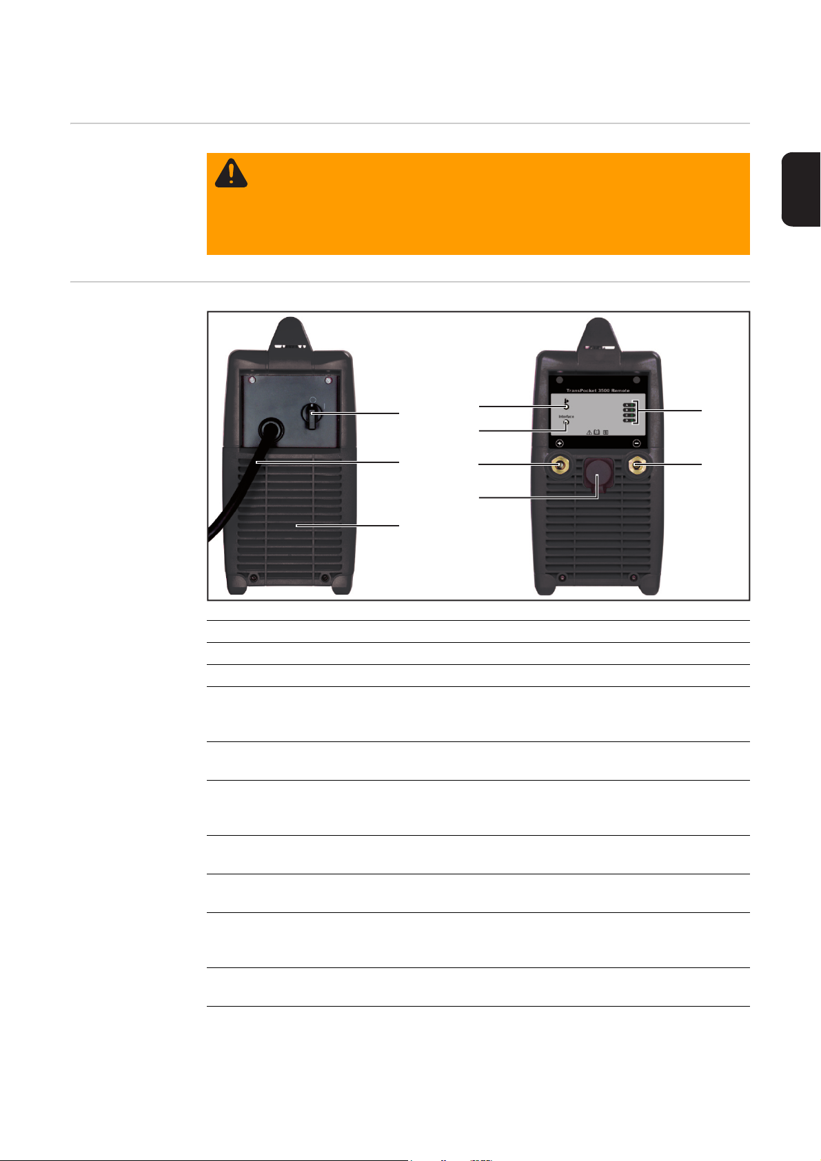
Control elements and connections
(1)
(2)
(4)
(5)
(6)
(7)
(8)
(9)
(3)
Safety
Control elements
and connections
WARNING! Operating the equipment incorrectly can cause serious injury and
damage. Do not use the functions described until you have thoroughly read and
understood the following documents:
- these operating instructions
- all the operating instructions for the system components, especially the safety rules
EN
Item Designation/function
(1) Mains switch
(2) Mains cable
(3) Dust filter ... where the fan draws in air
- Prevents contamination of the housing interior if large amounts of dust
haveaccumulated
(4) Overtemperature indicator
- comes on when the device is too hot
(5) Interface indicator
- lights green when the power source is ready
- flashes red if there is a fault
(6) (+) current socket
- with M12 internal thread
(7) LocalNet connection
- for connecting the ROB TSt interface
(8) Status indicator
- the status indicators provide information about the type of fault if the interface
indicator flashes red
(9) (+) current socket
- with M12 internal thread
51
Page 54

Before commissioning
Safety
Setup regulations
WARNING! Operating the equipment incorrectly can cause serious injury and
damage. Do not use the functions described until you have thoroughly read and
understood the following documents:
- these operating instructions
- all the operating instructions for the system components, especially the safety rules
WARNING! If one of these devices topples over or falls it could cause serious or
even fatal injury. Place units on a solid, level surface so that they remain stable.
The device is tested to IP 23 protection, meaning:
- protection against penetration by solid foreign bodies with diameters > 12 mm (0.49
in.)
- protection against direct sprays of water at any angle up to 60° from the vertical
Cooling air
The system must be set up in such a way that cooling air can flow unimpeded through the
slots in the front and rear panels.
Dust
Ensure that any metallic dust, for example from grinding work, is not sucked into the system by the fan.
Outdoor operation
The device can be set up and operated outdoors in accordance with IP23 degree of protection. Direct wetting (e.g. from rain) should be avoided.
Mains connection The device is designed to run at the mains voltage indicated on the rating plate. The re-
quired fuse protection for the mains supply can be found in the "Technical data" section. If
there is no mains cable or mains plug on your device, fit one that conforms to national
standards.
NOTE! Inadequately dimensioned electrical installations can cause serious damage. The incoming mains lead and its fuse must be dimensioned to suit the local
power supply. The technical data shown on the rating plate applies.
Generator-powered operation
The power source is generator-compatible, provided that the maximum apparent power
delivered by the generator is at least 22 kVA.
NOTE! The voltage delivered by the generator must never exceed the upper or
lower limits of the mains voltage tolerance range. Details of the mains voltage tolerance are given in the "Technical data" section.
52
Page 55

Setting the mains voltage
1
200V - 240V
2
2
1
3
General MVm machines (MultiVoltage manual) are suitable for operation with a mains voltage of
380 - 460V and a mains voltage of 200 - 240V.
NOTE! Machines are supplied with the 380 - 460V setting as standard. If the
mains voltage range needs to be reset, this must be done manually.
EN
Changing mains
voltage
WARNING! An electric shock can be fatal. Before opening the device
- Turn the mains switch to the "O" position
- Unplug the machine from the mains
- Prevent it from being switched on again
- Using a suitable measuring instrument, check to make sure that electrically
charged components (e.g. capacitors) have discharged
1
1
1
3
2
380V - 460V
2
3
1
2
4
53
Page 56

Rob TSt interface
Safety
Scope of supply
WARNING! Operating the equipment incorrectly can cause serious injury and
damage. Do not use the functions described until you have thoroughly read and
understood the following documents:
- these operating instructions
- all the operating instructions for the system components, especially the safety rules
(1)
(2)
(1) ROB TSt interface
(2) LocalNet cable harness (1 m)
Device concept The ROB TSt interface is an automated and robot interface with analogue and digital in-
puts and outputs. It is designed for installation in an automated or robot control cubicle (can
also be surface-mounted).
Features:
- Connection to power source via a standardised LocalNet interface
- No modification to power source necessary
- Analogue inputs and outputs for the transfer of process variables
- Therefore independent of the data processing bit width employed in the existing robot
control
- Easy to replace power source
- Simple plug connections
- Very little wiring required
- Mounted on DIN rail
- High degree of interference immunity during data transfer
- The power source is controlled by analogue set values
(0-10 V for welding current)
The robot interface is connected to the power source LocalNet connection by a 10-pin connecting lead.
The connecting lead is not included in the scope of supply and must be ordered separately.
A 1 m long LocalNet cable harness and a 10-pin connection socket are supplied with the
robot interface. The 10-pin connection socket is used as a bushing through the control cubicle.
54
Page 57

Overview "ROB TSt interface" comprises the following sections:
- Digital input signals (signals from robot)
- Analogue input signals (signals from robot)
- Digital output signals (signals to robot)
- Analogue output signals (signals to robot)
- Connection specifications
EN
55
Page 58

Digital input signals (signals from robot)
Parameters Signal level:
- LOW (0) .. 0 - 2.5 V
- HIGH (1) .. 18 - 30 V
Reference potential: GND = X7/2 or X12/2
NOTE! All signal states refer to the interface input, not the robot control.
Welding start
Pin X2/4 HIGH
The “Welding start” signal starts the welding process. The welding process remains active
while the “Welding start” signal is present.
Exception:
- The digital "Power source ready" output signal is absent
56
Page 59

Analogue input signals (signals from robot)
General The analogue differential amplifier inputs on the robot interface ensure that the robot inter-
face is electrically isolated from the analogue outputs on the robot control. Each input on
the robot interface has its own negative potential.
NOTE! The negative potentials of the inputs on the robot interface must be linked
together if the robot control uses a common "GND" connection for its analogue
output signals.
The analogue inputs described below are active at voltages of 0-10 V.
EN
Welding current
set value
Pin X2/1 Analogue in + 0 to + 10 V
Pin X2/8 Analogue in - (minus)
A voltage of 0 - 10 V is specified for the welding current set value.
- 1 V on the analogue input corresponds to a welding current of 100 A
- This corresponds to a welding current set value range of 0 - 1000 A
57
Page 60

Digital output signals (signals to robot)
General
Power source
ready
NOTE! If the connection between the power source and the ROB TSt interface
goes down, all digital and analogue output signals on the robot interface will be
set to “0”.
The power source supply voltage (24 V SECONDARY) is available in the ROB TSt interface.
24 V SECONDARY is electrically isolated from the LocalNet. A protective circuit limits excess voltages to 100 V.
Use pin X14/1 to select which voltage is to be connected to the digital outputs of the
ROB TSt interface:
- Robot control external voltage (24 V):
Connect the external voltage of the robot control digital output card (PLC) to pin X14/1
- Power source supply voltage (24 V SECONDARY):
Place a jumper between X14/1 and X14/7
Pin X2/14 24 V signal
Pin X7/2 or X12/2 or X5/10 GND
The “Power source ready” signal remains on for as long as the power source is ready for
operation.
The "Power source ready" signal drops out when a fault occurs on the power source.
Process active The “Process active” signal remains on for as long as the power source is in use.
In other words, an open circuit voltage or welding current is present on the current sockets.
Current flow The "Current flow" signal is set when the welding current is 10 A or higher.
58
Page 61

Analogue output signals (signals to robot)
General
Actual welding
voltage value
Actual welding
current value
NOTE! If the connection between the power source and the ROB TSt interface
goes down, all digital and analogue output signals on the robot interface will be
set to “0”.
The analogue outputs on the robot interface are used for setting up the robot and for displaying and documenting process parameters.
Pin X5/4 Analogue out + 0 to +10 V
Pin X5/11 Analogue out - (minus)
The actual welding voltage value is indicated by a voltage of 0 - 10 V on the analogue output.
- 1 V on the analogue output corresponds to a welding voltage of 10 V
- This corresponds to an actual welding voltage range of 0 - 100 V
Pin X2/3 Analogue out + 0 to +10 V
Pin X2/10 Analogue out - (minus)
The actual welding current value is indicated by a voltage of 0 - 10 V on the analogue output.
- 1 V on the analogue output corresponds to a welding current of 100 A
- This corresponds to an actual welding current range of 0 - 1000 A
EN
59
Page 62

Connection specifications
Input and output
wiring diagrams
Digital output wiring diagram
Digital input wiring diagram
Analogue output wiring diagram
60
Analogue input wiring diagram
Page 63

Application ex-
CURRENT FLOW (DIG. OUT)
WELDING START (DIG. IN)
X2/4
X5/11
X5/4
X2/10
X2/3
X14/1
X5/10
X4/7
X2/14
X8/10
X2/8
X2/1
X2/12
+24 V SECONDARY
GND SECONDARY
SUPPLY VOLTAGE
ample
EN
61
Page 64

Interface for field-bus systems
Safety
Scope of supply
Profibus interface
WARNING! Operating the equipment incorrectly can cause serious injury and
damage. Do not use the functions described until you have thoroughly read and
understood the following documents:
- these operating instructions
- all the operating instructions for the system components, especially the safety rules
(1) Profibus coupler BK3120
(1)
(2)
(3)
(4)
(2) Fronius LocalNet terminal KL6021-
0010
(3) End terminal KL9010
(4) LocalNet cable harness (1m)
Device concept
Profibus
Overview "Interface for field-bus systems" comprises the following sections:
Profibus is a manufacturer-independent open field bus standard, used in many different
applications in manufacturing, process and building automation. Profibus is suitable for
high-speed, time-critical data transfer, as well as extensive and complex communication
tasks.
Profibus is characterised by its small footprint and high degree of modularity. The fact that
it can simply be fitted to a standard C-rail (thus saving space) and employs direct cabling
of actuators and sensors without any interconnections between the terminals makes installation very straightforward. The uniform labelling system further simplifies the installation
process.
NOTE! The restriction of 128 input and output bytes imposed by the use of the
BK3120 bus coupler means that a maximum of 8 power sources can be controlled
simultaneously.
- Input and output signals for field-bus systems
- Descriptions of field-bus system signals
62
Page 65

Input and output signals for field-bus systems
Input signals
(from robot to
power source)
Seq. no. Signal designation Range Activity
E01 - E05 Not used - E06 Ping-pong - High
E07 - E08 Not used - -
E09 Start process - High
E10 - E16 Not used - -
E17 - E32 Not used - -
Current set value 0 - 3500
(0.0 - 350.0 A)
E33 - E40 High Byte - E41 - E48 Low Byte - -
E49 - E112 Not used - -
EN
Output signals
(from power
source to robot)
E113 - E224 Same signal assignment as E01 - E112 for
power source no. 2
E225 - E336 Same signal assignment as E01 - E112 for
power source no. 3
.
:
:
E785 - E896 Same signal assignment as E01 - E112 for
power source no. 8
Seq. no. Signal designation Range Activity
A01 - A08 Error numbers 0 - 255 -
A09 Current flow - High
A10 Ping-pong - High
A11 Process active - High
A12 Arc stable - High
A13 Not used - A14 Power source ready - High
A15 Communication ready - High
A16 Not used - -
63
Page 66

Seq. no. Signal designation Range Activity
A17 - A32 Not used - -
Voltage actual value 0 - 1000
(0.0 - 100.0 V)
A33 - A40 High Byte - A41 - A48 Low Byte - -
Current actual value 0 - 3500
(0.0 - 350.0 A)
A49 - A56 High Byte - A57 - A64 Low Byte - -
A65 - A112 Not used - -
A113 - A224 Same signal assignment as A01 - A112 for
power source no. 2
A225 - A336 Same signal assignment as A01 - A112 for
power source no. 3
.
:
:
A785 - A896 Same signal assignment as A01 - A112 for
power source no. 8
64
Page 67

Description of field-bus system signals
Description of input signals (from
robot to power
source)
Seq. no. Signal designation Signal description
E01 - E05 Not used
E06 Ping-pong Used to monitor the response time of the pow-
er source
E07 - E08 Not used
E09 Start process 0 stops the process
1 starts the process
E10 - E16 Not used
E17 - E32 Not used
Current set value
E33 - E40 High Byte Value for the desired welding current in 0.1 A
E41 - E48 Low Byte
E49 - E112 Not used
steps
A value of 0 sets the minimum current value of
5A.
EN
Description of
output signals
(from power
source to robot)
E113 E224
E225 E336
E785 E896
Seq. no. Signal designation Signal description
A01 - A08 Error numbers The error number is an 8-bit value that is great-
Same signal assignment as
E01 - E112 for power
source no. 2
Same signal assignment as
E01 - E112 for power
source no. 3
.
:
:
Same signal assignment as
E01 - E112 for power
source no. 8
er than 0 when an error occurs.
More information can be found in the "Troubleshooting" section
A09 Current flow 01Welding current < 5 A
Welding current >= 5 A
A10 Ping-pong
65
Page 68

Seq. no. Signal designation Signal description
A11 Process active 01Power source not active
Power source delivering power
(open circuit voltage or welding power)
A12 Arc stable 01Welding current < 5 A or
welding voltage < 10 V
Welding current > 5 A and
welding voltage > 10 V
A13 Not used
A14 Power source ready 01Power source not ready => see "Trouble-
shooting" section
Power source ready
A15 Communication ready 01No communication between KL6021 and
power source
Communication between KL6021 and pow-
er source OK
A16 Not used
A17 - A32 Not used
Voltage actual value
A33 - A40 High Byte Value of actual welding or open circuit voltA41 - A48 Low Byte
age in 0.1 V steps
Current actual value
A49 - A56 High Byte Value of actual welding current in 0.1 A
A57 - A64 Low Byte
A65 - A112 Not used
A113 A224
A225 A336
A785 A896
Same signal assignment as
A01 - A112 for power
source no. 2
Same signal assignment as
A01 - A112 for power
source no. 3
.
:
:
Same signal assignment as
A01 - A112 for power
source no. 8
steps
66
Page 69

Troubleshooting
General The power source is fitted with an intelligent safety system that allows fuses to be dis-
pensed with entirely. After a possible malfunction or error has been remedied, the power
source can be put back into normal operation again without any fuses having to be replaced.
EN
Safety
Fault diagnosis
WARNING! An electric shock can be fatal. Before opening the device
- Turn the mains switch to the "O" position
- Unplug the machine from the mains
- Prevent it from being switched on again
- Using a suitable measuring instrument, check to make sure that electrically
charged components (e.g. capacitors) have discharged
CAUTION! Inadequate PE conductor connections can cause serious injury and
damage. The housing screws provide a suitable PE conductor connection for
earthing (grounding) the housing and must NOT be replaced by any other screws
which do not provide a reliable PE conductor connection.
Power source has no function
Mains switch is on, but indicators are not lit up
Cause: There is a break in the mains lead; the mains plug is not plugged in
Remedy: Check the mains lead, ensure that the mains plug is plugged in
Cause: Mains socket or mains plug faulty
Remedy: Replace faulty parts
Cause: Mains fuse protection
Remedy: Change the mains fuse protection
No welding current
Mains switch is ON, overtemperature indicator is lit up
Cause: Overload
Remedy: Check duty cycle
Cause: Thermostatic safety cut-out has tripped
Remedy: Wait until the power source automatically comes back on at the end of the
cooling phase
Cause: Insufficient cooling air intake
Remedy: Ensure adequate air supply
Cause: Power module very dirty
Remedy: Clean device using dry compressed air (see "Care and maintenance")
Cause: The fan in the power source is faulty
Remedy: Have device serviced
67
Page 70

Mains fuse or automatic circuit breaker has tripped
Cause: Mains fuse underrated
Remedy: Rate fuse according to the "Technical data" section
Cause: Mains fuse trips in open circuit
Remedy: Have device serviced
Status indicators
NOTE! When using an interface for field-bus systems, the indicators A - D show
the error number in binary code (column "No." in the table below).
Example showing the relationship between indicator and number: D C B A = 0 1 0 1 = 5
Description Indicator No.
Test mode
Interface indicator flashes green
Cause: Not an error, test mode with TR 3000 remote control
Remedy: Not required
Primary current
Indicators shown on the right light up, interface indicator flashes red
Cause: Internal fault
Remedy: - Switch device off and back on again
- Fault keeps recurring => have device serviced
Interface
A
B
C
0
1
D
Asymmetry (when switching on)
Indicators shown on the right light up, interface indicator flashes red
Cause: Internal fault
Remedy: - Switch device off and back on again
- Fault keeps recurring => have device serviced
A
B
2
C
D
Asymmetry (during operation)
Indicators shown on the right light up, interface indicator flashes red
Cause: Internal fault
Remedy: - Switch device off and back on again
- Fault keeps recurring => have device serviced
ILZ (current zero crossing)
Indicators shown on the right light up, interface indicator flashes red
Cause: Signal for current zero crossing not present
Remedy: - Switch device off and back on again
- Fault keeps recurring => have device serviced
Current limit
Indicators shown on the right light up, interface indicator flashes red
Cause: Internal fault
Remedy: - Switch device off and back on again
- Fault keeps recurring => have device serviced
A
B
3
C
D
A
B
4
C
D
A
B
5
C
D
68
Page 71

Description Indicator No.
Interface
Interface
Earth current (earth current watchdog option only)
Indicators shown on the right light up, interface indicator flashes red
Cause: Current flowing via device earth
Remedy: - Check ground earth connection to the workpiece
- Switch device off and back on again
- Fault keeps recurring => have device serviced
Mains undervoltage or overvoltage
Indicators shown on the right light up, interface indicator flashes red
Cause: The mains voltage is outside the tolerance range
Remedy: - Check the mains voltage
- Switch device off and back on again
- Fault keeps recurring => have device serviced
Open circuit
Indicators shown on the right light up, interface indicator flashes red
Cause: Output voltage is greater than 113 V
Remedy: Switch machine off and on again;
if fault keeps recurring, have device serviced
A
B
7
C
D
A
B
C
8
D
A
B
9
C
D
Working voltage
Indicators shown on the right light up, interface indicator flashes red
Cause: Working voltage >45 V and >2 seconds
Remedy: Remove start signal =>
=> Check process =>
=> Set start signal again
A
B
11
C
D
EN
OvertemperatureB
Overtemperature indicator lights up, interface indicator flashes red
Cause: Power source exceeded max. temperature
Remedy: Wait until the device has cooled down
Acknowledges automatically after cooling down
No communication
Interface indicator flashes red
Cause: No communication
Remedy: Check interface cable
Acknowledges automatically when communication is established
16
150
69
Page 72

Care, maintenance and disposal
Safety
General Under normal operating conditions, the device requires only a minimum of care and main-
tenance. However, it is vital to observe some important points to ensure the device remains
in a usable condition for many years.
WARNING! Work that is carried out incorrectly can cause serious injury or damage. The following activities must only be carried out by trained and qualified personnel. Observe the safety rules in the power source operating instructions.
WARNING! An electric shock can be fatal. Before opening the unit
- Turn the mains switch to the "O" position
- Unplug the device from the mains
- Put up an easy-to-understand warning sign to stop anybody inadvertently
switching it back on again
- Using a suitable measuring device, check to make sure that electrically
charged components (e.g. capacitors) have discharged
CAUTION! Inadequate PE conductor connections can cause serious injury and
damage. The housing screws provide a suitable PE conductor connection for
earthing (grounding) the housing and must NOT be replaced by any other screws
which do not provide a reliable PE conductor connection.
At every start-up - Check the mains plug, mains cable and ground (earth) connection for damage
- Check that there is a gap of 0.5 m (1 ft. 7.69 in.) all around the machine to ensure that
cooling air can flow and escape unhindered
NOTE! Air inlets and outlets must never be covered, not even partially.
Every 2 months - Clean any upstream air filters
Every 6 months
- open the device
- clean out the device interior using dry compressed air at reduced pressure
- if a lot of dust has accumulated, clean the cooling air ducts.
Disposal Dispose of in accordance with the applicable national and local regulations.
NOTE! Risk of damage to electronic components. Do not bring air nozzle too
close to electronic components.
70
Page 73

Technical data
TP 3500 CC Remote
Mains voltage 3 x 200 | 230 | 240 | 380 | 400 | 460 V
Mains voltage tolerance +/- 10 %
Mains frequency 50/60 Hz
Mains fuse protection 32 A slow-blow
Primary cont. power (100% duty cycle) 12,2 kVA
Mains connection
Primary continuous current
1)
Restrictions possible
28,2 | 25,4 | 24,5 | 17,5 | 16,8 | 15,0 A
at 220 A / 28,8 V secondary
No load power 109 | 130 | 140 | 289 | 315 | 410 VA
Cos phi at 350 A 0.99
Efficiency at 220 A / 28,8 V 87 %
at 150 A / 40,0 V 89 %
Welding current range 10 - 350 A
Welding power at 10 min / 40 °C (104 °F) 35 % d.c.
10 min / 40 °C (104 °F) 60 % d.c.
10 min / 40 °C (104 °F) 100 % d.c.
10 min / 40 °C (104 °F) 100 % d.c.
Apparent power at 10 min / 40 °C (104 °F) 35 % d.c.
10 min / 40 °C (104 °F) 60 % d.c.
10 min / 40 °C (104 °F) 100 % d.c.
10 min / 40 °C (104 °F) 100 % d.c.
2)
2)
2)
2)
2)
2)
2)
2)
350 A / 34,0 V
280 A / 31,2 V
220 A / 28,8 V
150 A / 40,0 V
19,9 kVA
15,5 kVA
11,3 kVA
11,0 kVA
Max. welding voltage at 350 A 40,7 | 47,2 | 47,3 | 40,8 | 43,1 | 47,2 V
Open circuit voltage 89 V
Degree of protection IP 23
Type of cooling AF
Insulation class B
Marks of conformity CE
Safety symbols S
Dimensions l x w x h 500 x 190 x 380 mm
19.68 x 7.48 x 14.96 in.
Weight 20,1 kg (44.3 lb.)
Overvoltage category III
Pollution level according to IEC60664 3
Ventilation capacity approx. 6 m³ / minute
EN
ROB TSt interface
1)
connected to public grid at 230/400 V and 50 Hz
2)
d.c. = Duty cycle
Marks of conformity CE
Dimensions l x w x h 160 x 90 x 58 mm
Weight 1.05 kg
71
Page 74

72
Page 75

Appendix
Page 76

Spare parts list: TransPocket 3500 CC Remote
42,0405,0536
42,0201,2190
32,0405,0183
43,0004,2786
42,0201,2190
42,0405,0538
42,0405,0540
45,0200,1374
AS2,0201,2189
43,0001,3358
Transpocket 3500 CC Remote 4,075,150,631,R
42,0300,7158
42,0300,7159
A
B
C
D
Interface
x2
x2
TransPocket 3500 Remote
45,0200,1375
42,0405,0542
42,0409,3144
42,0201,2357
74
Page 77

43,0004,2784
41,0002,0060
43,0004,2967
STTP2
4,070,916,Z - LCA35
4,071,323,Z - STTP2 REM
LCA35
43,0001,1324
33,0010,0362
43,0010,0365
43,0002,0417
43,0006,0219
43,0001,1257
42,0406,0294
42,0300,1815
43,0004,0664
42,0300,7160
41,0001,0668
43,0010,0350
33,0005,4143
10pol.
14pol.
REM
75
Page 78

Circuit diagram: TransPocket 3500 CC Remote
76
Page 79

77
Page 80

FRONIUS INTERNATIONAL GMBH
Froniusplatz 1, A-4600 Wels, Austria
Tel: +43 (0)7242 241-0, Fax: +43 (0)7242 241-3940
Under http://www.fronius.com/addresses you will find all addresses
of our Sales & service partners and Locations
E-Mail: sales@fronius.com
www.fronius.com
www.fronius.com/addresses
 Loading...