

Page 1

/ Battery Charging Systems / Welding Technology / Solar Electronics
TransPocket 1100 / 1200
Bedienungsanleitung
Ersatzteilliste
DEENFR
E-Hand Stromquelle
Operating Instructions
Spare Parts List
MMA power source
Instructions de service
Liste de pièces de rechange
Source de courant électriquemanuel
42,0410,0709 007-08112013
Page 2

Page 3

Sehr geehrter Leser
DE
Einleitung
Wir danken Ihnen für Ihr entgegengebrachtes Vertrauen und gratulieren Ihnen zu Ihrem
technisch hochwertigen Fronius Produkt. Die vorliegende Anleitung hilft Ihnen, sich mit
diesem vertraut zu machen. Indem Sie die Anleitung sorgfältig lesen, lernen Sie die
vielfältigen Möglichkeiten Ihres Fronius-Produktes kennen. Nur so können Sie seine
Vorteile bestmöglich nutzen.
Bitte beachten Sie auch die Sicherheitsvorschriften und sorgen Sie so für mehr Sicherheit am Einsatzort des Produktes. Sorgfältiger Umgang mit Ihrem Produkt unterstützt
dessen langlebige Qualität und Zuverlässigkeit. Das sind wesentliche Voraussetzungen
für hervorragende Ergebnisse.
ud_fr_st_et_00491 01/2012
Page 4

Page 5

Sicherheitsvorschriften
DE
GEFAHR!
WARNUNG!
VORSICHT!
HINWEIS!
Wichtig!
„GEFAHR!“ Bezeichnet eine unmittelbar drohende Gefahr. Wenn sie nicht
gemieden wird, sind Tod oder schwerste Verletzungen die Folge.
„WARNUNG!“ Bezeichnet eine möglicherweise gefährliche Situation. Wenn
sie nicht gemieden wird, können Tod und schwerste Verletzungen die Folge
sein.
„VORSICHT!“ Bezeichnet eine möglicherweise schädliche Situation. Wenn
sie nicht gemieden wird, können leichte oder geringfügige Verletzungen
sowie Sachschäden die Folge sein.
„HINWEIS!“ bezeichnet die Gefahr beeinträchtigter Arbeitsergebnisse und
möglicher Schäden an der Ausrüstung.
„Wichtig!“ bezeichnet Anwendungstipps und andere besonders nützliche Informationen.
Es ist kein Signalwort für eine schädliche oder gefährliche Situation.
Wenn Sie eines der im Kapitel „Sicherheitsvorschriften“ abgebildeten Symbole sehen, ist
erhöhte Achtsamkeit erforderlich.
Allgemeines
Das Gerät ist nach dem Stand der Technik und den anerkannten sicherheitstechnischen Regeln gefertigt. Dennoch drohen bei Fehlbedienung oder
Missbrauch Gefahr für
- Leib und Leben des Bedieners oder Dritte,
- das Gerät und andere Sachwerte des Betreibers,
- die effiziente Arbeit mit dem Gerät.
Alle Personen, die mit der Inbetriebnahme, Bedienung, Wartung und Instandhaltung des Gerätes zu tun haben, müssen
- entsprechend qualifiziert sein,
- Kenntnisse vom Schweißen haben und
- diese Bedienungsanleitung vollständig lesen und genau befolgen.
Die Bedienungsanleitung ist ständig am Einsatzort des Gerätes aufzubewahren. Ergänzend zur Bedienungsanleitung sind die allgemein gültigen sowie
die örtlichen Regeln zu Unfallverhütung und Umweltschutz bereitzustellen
und zu beachten.
Alle Sicherheits- und Gefahrenhinweise am Gerät
- in lesbarem Zustand halten
- nicht beschädigen, nicht entfernen
- nicht abdecken, überkleben oder übermalen.
Die Positionen der Sicherheits- und Gefahrenhinweise am Gerät, entnehmen
Sie dem Kapitel „Allgemeines“ der Bedienungsanleitung Ihres Gerätes.
Störungen, die die Sicherheit beeinträchtigen können, vor dem Einschalten
des Gerätes beseitigen.
Es geht um Ihre Sicherheit!
I
ud_fr_st_sv_00466 022013
Page 6

Bestimmungsgemäße Verwendung
Das Gerät ist ausschließlich für Arbeiten im Sinne der bestimmungsgemäßen Verwendung zu benutzen.
Das Gerät ist ausschließlich für die am Leistungsschild angegebenen
Schweißverfahren bestimmt.
Eine andere oder darüber hinaus gehende Benutzung gilt als nicht bestimmungsgemäß. Für hieraus entstandene Schäden haftet der Hersteller nicht.
Zur bestimmungsgemäßen Verwendung gehört auch
- das vollständige Lesen und Befolgen aller Hinweise aus der Bedienungsanleitung
- das vollständige Lesen und Befolgen aller Sicherheits- und Gefahrenhinweise
- die Einhaltung der Inspektions- und Wartungsarbeiten.
Das Gerät niemals für folgende Anwendungen verwenden:
- Auftauen von Rohren
- Laden von Batterien/Akkumulatoren
- Start von Motoren
Das Gerät ist für den Betrieb in Industrie und Gewerbe ausgelegt. Für Schäden, die auf den Einsatz im Wohnbereich zurückzuführen sind, haftet der
Hersteller nicht.
Für mangelhafte oder fehlerhafte Arbeitsergebnisse übernimmt der Hersteller
ebenfalls keine Haftung.
Umgebungsbedingungen
Verpflichtungen
des Betreibers
Betrieb oder Lagerung des Gerätes außerhalb des angegebenen Bereiches
gilt als nicht bestimmungsgemäß. Für hieraus entstandene Schäden haftet
der Hersteller nicht.
Temperaturbereich der Umgebungsluft:
- beim Betrieb: -10 °C bis + 40 °C (14 °F bis 104 °F)
- bei Transport und Lagerung: - 20 °C bis + 55 °C (-4 °F bis 131 °F)
Relative Luftfeuchtigkeit:
- bis 50 % bei 40 °C (104 °F)
- bis 90 % bei 20 °C (68 °F)
Umgebungsluft: frei von Staub, Säuren, korrosiven Gasen oder Substanzen,
usw.
Höhenlage über dem Meeresspiegel: bis 2000 m (6500 ft)
Der Betreiber verpflichtet sich, nur Personen am Gerät arbeiten zu lassen,
die
- mit den grundlegenden Vorschriften über Arbeitssicherheit und Unfallverhütung vertraut und in die Handhabung des Gerätes eingewiesen sind
- diese Bedienungsanleitung, insbesondere das Kapitel „Sicherheitsvorschriften“ gelesen, verstanden und dies durch ihre Unterschrift bestätigt
haben
- entsprechend den Anforderungen an die Arbeitsergebnisse ausgebildet
sind.
ud_fr_st_sv_00466 022013
Das sicherheitsbewusste Arbeiten des Personals ist in regelmäßigen Abständen zu überprüfen.
II
Page 7

Verpflichtungen
des Personals
Alle Personen, die mit Arbeiten am Gerät beauftragt sind, verpflichten sich,
vor Arbeitsbeginn
- die grundlegenden Vorschriften über Arbeitssicherheit und Unfallverhütung zu befolgen
- diese Bedienungsanleitung, insbesondere das Kapitel „Sicherheitsvorschriften“ zu lesen und durch ihre Unterschrift zu bestätigen, dass sie
diese verstanden haben und befolgen werden.
Vor Verlassen des Arbeitsplatzes sicherstellen, dass auch in Abwesenheit
keine Personen- oder Sachschäden auftreten können.
DE
Netzanschluss
Selbst- und
Personenschutz
Geräte mit hoher Leistung können auf Grund ihrer Stromaufnahme die Energiequalität des Netzes beeinflussen.
Das kann einige Gerätetypen betreffen in Form von:
- Anschluss-Beschränkungen
- Anforderungen hinsichtlich maximal zulässiger Netzimpedanz
*)
- Anforderungen hinsichtlich minimal erforderlicher Kurzschluss-Leistung
*)
jeweils an der Schnittstelle zum öffentlichen Netz
siehe technische Daten
In diesem Fall muss sich der Betreiber oder der Anwender des Gerätes
versichern, ob das Gerät angeschlossen werden darf, gegebenenfalls durch
Rücksprache mit dem Energieversorgungs-Unternehmen.
HINWEIS! Auf eine sichere Erdung des Netzanschlusses ist zu
achten.
Beim Schweißen setzen Sie sich zahlreichen Gefahren aus, wie z.B.:
- Funkenflug, umherfliegende heiße Metallteile
- augen- und hautschädigende Lichtbogen-Strahlung
*)
- schädliche elektromagnetische Felder, die für Träger von Herzschrittmachern Lebensgefahr bedeuten
- elektrische Gefährdung durch Netz- und Schweißstrom
- erhöhte Lärmbelastung
- schädlichen Schweißrauch und Gase
Personen, die während des Schweißvorganges am Werkstück arbeiten,
müssen geeignete Schutzkleidung mit folgenden Eigenschaften verwenden:
- schwer entflammbar
- isolierend und trocken
- den ganzen Körper bedeckend, unbeschädigt und in gutem Zustand
- Schutzhelm
- stulpenlose Hose
III
ud_fr_st_sv_00466 022013
Page 8

Selbst- und
Personenschutz
(Fortsetzung)
Zur Schutzbekleidung zählt unter anderem:
- Augen und Gesicht durch Schutzschild mit vorschriftsgemäßem FilterEinsatz vor UV-Strahlen, Hitze und Funkenflug schützen.
- Hinter dem Schutzschild eine vorschriftsgemäße Schutzbrille mit Seitenschutz tragen.
- Festes, auch bei Nässe isolierendes Schuhwerk tragen
- Hände durch geeignete Handschuhe schützen (elektrisch isolierend,
Hitzeschutz).
- Zur Verringerung der Lärmbelastung und zum Schutz vor Verletzungen
Gehörschutz tragen.
Personen, vor allem Kinder, während des Betriebes von den Geräten und
dem Schweißprozess fernhalten. Befinden sich dennoch Personen in der
Nähe
- diese über alle Gefahren (Blendgefahr durch Lichtbogen, Verletzungsgefahr durch Funkenflug, gesundheitsschädlicher Schweißrauch, Lärmbelastung, mögliche Gefährdung durch Netz- oder Schweißstrom, ...)
unterrichten,
- geeignete Schutzmittel zur Verfügung stellen oder
- geeignete Schutzwände und -Vorhänge aufbauen.
Angaben zu
Geräuschemissionswerten
Gefahr durch
schädliche Gase
und Dämpfe
Das Gerät erzeugt einen maximalen Schallleistungspegel <80dB(A) (ref. 1pW)
bei Leerlauf sowie in der Kühlungsphase nach Betrieb entsprechend dem
maximal zulässigem Arbeitspunkt bei Normlast gemäß EN 60974-1.
Ein arbeitsplatzbezogener Emissionswert kann beim Schweißen (und Schneiden) nicht angegeben werden, da dieser verfahrens- und umgebungsbedingt
ist. Er ist abhängig von den verschiedensten Parametern wie z.B. Schweißverfahren (MIG/MAG-, WIG-Schweißen), der angewählten Stromart (Gleichstrom,
Wechselstrom), dem Leistungsbereich, der Art des Schweißgutes, dem
Resonanzverhalten des Werkstückes, der Arbeitsplatzumgebung u.a.m.
Beim Schweißen entstehender Rauch enthält gesundheitsschädliche Gase
und Dämpfe.
Schweißrauch enthält Substanzen, die unter Umständen Geburtsschäden
und Krebs verursachen können.
Kopf von entstehendem Schweißrauch und Gasen fernhalten.
Entstehenden Rauch sowie schädliche Gase
- nicht einatmen
- durch geeignete Mittel aus dem Arbeitsbereich absaugen.
ud_fr_st_sv_00466 022013
Für ausreichend Frischluft-Zufuhr sorgen.
Bei nicht ausreichender Belüftung Atem-Schutzmaske mit Luftzufuhr verwenden.
Besteht Unklarheit darüber, ob die Absaugleistung ausreicht, die gemessenen Schadstoff-Emissionswerte mit den zulässigen Grenzwerten vergleichen.
Wird nicht geschweißt, das Ventil der Schutzgas-Flasche oder Hauptgasversorgung schließen.
IV
Page 9

Gefahr durch
schädliche Gase
und Dämpfe
(Fortsetzung)
Folgende Komponenten sind unter anderem für den Grad der Schädlichkeit
des Schweißrauches verantwortlich:
- Für das Werkstück eingesetzte Metalle
- Elektroden
- Beschichtungen
- Reiniger, Entfetter und dergleichen
Daher die entsprechenden Materialsicherheits-Datenblätter und Herstellerangaben zu den aufgezählten Komponenten berücksichtigen.
Entzündliche Dämpfe (z.B. Lösungsmittel-Dämpfe) vom Strahlungsbereich
des Lichtbogens fernhalten.
DE
Gefahr durch
Funkenflug
Gefahren durch
Netz- und
Schweißstrom
Funkenflug kann Brände und Explosionen auslösen.
Niemals in der Nähe brennbarer Materialien schweißen.
Brennbare Materialien müssen mindestens 11 Meter (36 ft. 1.07 in.) vom
Lichtbogen entfernt sein oder mit einer geprüften Abdeckung zugedeckt
werden.
Geeigneten, geprüften Feuerlöscher bereithalten.
Funken und heiße Metallteile können auch durch kleine Ritzen und Öffnungen in umliegende Bereiche gelangen. Entsprechende Maßnahmen ergreifen, dass dennoch keine Verletzungs- und Brandgefahr besteht.
Nicht in feuer- und explosionsgefährdeten Bereichen und an geschlossenen
Tanks, Fässern oder Rohren schweißen, wenn diese nicht gemäß den
entsprechenden nationalen und internationalen Normen vorbereitet sind.
An Behältern in denen Gase, Treibstoffe, Mineralöle und dgl. gelagert sind/
waren, darf nicht geschweißt werden. Durch Rückstände besteht Explosionsgefahr.
Ein elektrischer Schlag ist grundsätzlich lebensgefährlich und kann tödlich
sein.
Spannungsführende Teile innerhalb und außerhalb des Gerätes nicht berühren.
Beim MIG/MAG- und WIG-Schweißen sind auch der Schweißdraht, die
Drahtspule, die Antriebsrollen sowie alle Metallteile, die mit dem Schweißdraht in Verbindung stehen, spannungsführend.
Den Drahtvorschub immer auf einem ausreichend isolierten Untergrund
aufstellen oder eine geeignete, isolierende Drahtvorschub-Aufnahme verwenden.
Für geeigneten Selbst- und Personenschutz durch gegenüber dem Erd- oder
Massepotential ausreichend isolierende, trockene Unterlage oder Abdeckung
sorgen. Die Unterlage oder Abdeckung muss den gesamten Bereich zwischen Körper und Erd- oder Massepotential vollständig abdecken.
Sämtliche Kabel und Leitungen müssen fest, unbeschädigt, isoliert und
ausreichend dimensioniert sein. Lose Verbindungen, angeschmorte, beschädigte oder unterdimensionierte Kabel und Leitungen sofort erneuern.
V
ud_fr_st_sv_00466 022013
Page 10

Gefahren durch
Netz- und
Schweißstrom
(Fortsetzung)
Kabel oder Leitungen weder um den Körper noch um Körperteile schlingen.
Die Schweiß-Elektrode (Stabelektrode, Wolframelektrode, Schweißdraht, ...)
- niemals zur Kühlung in Flüssigkeiten eintauchen
- niemals bei eingeschalteter Stromquelle berühren.
Zwischen den Schweiß-Elektroden zweier Schweißgeräte kann zum Beispiel
die doppelte Leerlauf-Spannung eines Schweißgerätes auftreten. Bei gleichzeitiger Berührung der Potentiale beider Elektroden besteht unter Umständen Lebensgefahr.
Netz- und Gerätezuleitung regelmäßig von einer Elektro-Fachkraft auf
Funktionstüchtigkeit des Schutzleiters überprüfen lassen.
Das Gerät nur an einem Netz mit Schutzleiter und einer Steckdose mit
Schutzleiter-Kontakt betreiben.
Wird das Gerät an einem Netz ohne Schutzleiter und an einer Steckdose
ohne Schutzleiter-Kontakt betrieben, gilt dies als grob fahrlässig. Für hieraus
entstandene Schäden haftet der Hersteller nicht.
Falls erforderlich, durch geeignete Mittel für eine ausreichende Erdung des
Werkstückes sorgen.
Nicht verwendete Geräte ausschalten.
Vagabundierende
Schweißströme
Bei Arbeiten in größerer Höhe Sicherheitsgeschirr zur Absturzsicherung
tragen.
Vor Arbeiten am Gerät das Gerät abschalten und Netzstecker ziehen.
Das Gerät durch ein deutlich lesbares und verständliches Warnschild gegen
Anstecken des Netzsteckers und Wiedereinschalten sichern.
Nach dem Öffnen des Gerätes:
- alle Bauteile die elektrische Ladungen speichern entladen
- sicherstellen, dass alle Komponenten des Gerätes stromlos sind.
Sind Arbeiten an spannungsführenden Teilen notwendig, eine zweite Person
hinzuziehen, die den Hauptschalter rechtzeitig ausschaltet.
Werden die nachfolgend angegebenen Hinweise nicht beachtet, ist die
Entstehung vagabundierender Schweißströme möglich, die folgendes verursachen können:
- Feuergefahr
- Überhitzung von Bauteilen, die mit dem Werkstück verbunden sind
- Zerstörung von Schutzleitern
- Beschädigung des Gerätes und anderer elektrischer Einrichtungen
ud_fr_st_sv_00466 022013
Für eine feste Verbindung der Werkstück-Klemme mit dem Werkstück
sorgen.
Werkstück-Klemme möglichst nahe an der zu schweißenden Stelle befestigen.
Bei elektrisch leitfähigem Boden, das Gerät mit ausreichender Isolierung
gegenüber dem Boden aufstellen.
VI
Page 11

Vagabundierende
Schweißströme
(Fortsetzung)
Bei Verwendung von Stromverteilern, Doppelkopf-Aufnahmen, etc., folgendes beachten: Auch die Elektrode des nicht verwendeten Schweißbrenners /
Elektrodenhalters ist potentialführend. Sorgen Sie für eine ausreichend
isolierende Lagerung des nicht verwendeten Schweißbrenners / Elektrodenhalters.
Bei automatisierten MIG/MAG Anwendungen die Drahtelektrode nur isoliert
von Schweißdraht-Fass, Großspule oder Drahtspule zum Drahtvorschub
führen.
DE
EMV GeräteKlassifizierungen
Geräte der Emissionsklasse A:
- sind nur für den Gebrauch in Industriegebieten vorgesehen
- können in anderen Gebieten leitungsgebundene und gestrahlte Störungen verursachen.
Geräte der Emissionsklasse B:
- erfüllen die Emissionsanforderungen für Wohn- und Industriegebiete.
Dies gilt auch für Wohngebiete, in denen die Energieversorgung aus
dem öffentlichen Niederspannungsnetz erfolgt.
EMV Geräte-Klassifizierung gemäß Leistungsschild oder technischen Daten
EMV-Maßnahmen In besonderen Fällen können trotz Einhaltung der genormten Emissions-
Grenzwerte Beeinflussungen für das vorgesehene Anwendungsgebiet
auftreten (z.B. wenn empfindliche Geräte am Aufstellungsort sind oder wenn
der Aufstellungsort in der Nähe von Radio- oder Fernsehempfängern ist).
In diesem Fall ist der Betreiber verpflichtet, angemessene Maßnahmen für
die Störungsbehebung zu ergreifen.
Mögliche Probleme und Störfestigkeit von Einrichtungen in der Umgebung
gemäß nationalen und internationalen Bestimmungen prüfen und bewerten:
- Sicherheitseinrichtungen
- Netz-, Signal- und Daten-Übertragungsleitungen
- EDV- und Telekommunikations-Einrichtugen
- Einrichtungen zum Messen und Kalibrieren
Unterstützende Maßnahmen zur Vermeidung von EMV-Problemen:
a) Netzversorgung
- Treten elektromagnetische Störungen trotz vorschriftsgemäßem Netzanschluss auf, zusätzliche Maßnahmen ergreifen (z.B. geeigneten Netzfilter verwenden).
b) Schweißleitungen
- so kurz wie möglich halten
- eng zusammen verlaufen lassen (auch zur Vermeidung von EMFProblemen)
- weit entfernt von anderen Leitungen verlegen
c) Potentialausgleich
d) Erdung des Werkstückes
- Falls erforderlich, Erdverbindung über geeignete Kondensatoren herstellen.
e) Abschirmung, falls erforderlich
- Andere Einrichtungen in der Umgebung abschirmen
- Gesamte Schweißinstallation abschirmen
VII
ud_fr_st_sv_00466 022013
Page 12

EMF-Maßnahmen Elektromagnetische Felder können Gesundheitsschäden verursachen, die
noch nicht bekannt sind:
- Auswirkungen auf die Gesundheit benachbarter Personen, z.B. Träger
von Herzschrittmachern und Hörhilfen
- Träger von Herzschrittmachern müssen sich von ihrem Arzt beraten
lassen, bevor sie sich in unmittelbare Nähe des Gerätes und des
Schweißprozesses aufhalten
- Abstände zwischen Schweißkabeln und Kopf/Rumpf des Schweißers
aus Sicherheitsgründen so groß wie möglich halten
- Schweißkabeln und Schlauchpakete nicht über der Schulter tragen und
nicht um den Körper und Körperteile wickeln
Besondere
Gefahrenstellen
Hände, Haare, Kleidungsstücke und Werkzeuge von beweglichen Teilen
fernhalten, wie zum Beispiel:
- Ventilatoren
- Zahnrädern
- Rollen
- Wellen
- Drahtspulen und Schweißdrähten
Nicht in rotierende Zahnräder des Drahtantriebes oder in rotierende Antriebsteile greifen.
Abdeckungen und Seitenteile dürfen nur für die Dauer von Wartungs- und
Reparaturarbeiten geöffnet / entfernt werden.
Während des Betriebes
- Sicherstellen, dass alle Abdeckungen geschlossen und sämtliche
Seitenteile ordnungsgemäß montiert sind.
- Alle Abdeckungen und Seitenteile geschlossen halten.
Austritt des Schweißdrahtes aus dem Schweißbrenner bedeutet ein hohes
Verletzungsrisiko (Durchstechen der Hand, Verletzung von Gesicht und
Augen, ...).
Daher stets den Brenner vom Körper weghalten (Geräte mit Drahtvorschub)
und eine geeignete Schutzbrille verwenden.
ud_fr_st_sv_00466 022013
Werkstück während und nach dem Schweißen nicht berühren - Verbrennungsgefahr.
Von abkühlenden Werkstücken kann Schlacke abspringen. Daher auch bei
Nacharbeiten von Werkstücken die vorschriftsgemäße Schutzausrüstung
tragen und für ausreichenden Schutz anderer Personen sorgen.
Schweißbrenner und andere Ausrüstungskomponenten mit hoher Betriebstemperatur abkühlen lassen, bevor an ihnen gearbeitet wird.
In feuer- und explosionsgefährdeten Räumen gelten besondere Vorschriften entsprechende nationale und internationale Bestimmungen beachten.
Stromquellen für Arbeiten in Räumen mit erhöhter elektrischer Gefährdung
(z.B. Kessel) müssen mit dem Zeichen (Safety) gekennzeichnet sein. Die
Stromquelle darf sich jedoch nicht in solchen Räumen befinden.
VIII
Page 13

Besondere
Gefahrenstellen
(Fortsetzung)
Verbrühungsgefahr durch austretendes Kühlmittel. Vor dem Abstecken von
Anschlüssen für den Wasservorlauf oder -rücklauf, das Kühlgerät abschalten.
Beim Hantieren mit Kühlmittel, die Angaben de Kühlmittel-Sicherheitsdatenblattes beachten. Das Kühlmittel-Sicherheitsdatenblatt erhalten Sie bei Ihrer
Service-Stelle oder über die Homepage des Herstellers.
Für den Krantransport von Geräten nur geeignete Last-Aufnahmemittel des
Herstellers verwenden.
- Ketten oder Seile an allen vorgesehenen Aufhängungspunkten des
geeigneten Last-Aufnahmemittels einhängen.
- Ketten oder Seile müssen einen möglichst kleinen Winkel zur Senkrechten einnehmen.
- Gasflasche und Drahtvorschub (MIG/MAG- und WIG-Geräte) entfernen.
Bei Kran-Aufhängung des Drahtvorschubes während des Schweißens,
immer eine geeignete, isolierende Drahtvorschub-Aufhängung verwenden
(MIG/MAG- und WIG-Geräte).
Ist das Gerät mit einem Tragegurt oder Tragegriff ausgestattet, so dient
dieser ausschließlich für den Transport per Hand. Für einen Transport mittels
Kran, Gabelstapler oder anderen mechanischen Hebewerkzeugen, ist der
Tragegurt nicht geeignet.
DE
Beeinträchtigung
der Schweißergebnisse
Alle Anschlagmittel (Gurte, Schnallen, Ketten, etc.) welche im Zusammenhang mit dem Gerät oder seinen Komponenten verwendet werden, sind regelmäßig zu überprüfen (z.B. auf mechanische Beschädigungen, Korrosion oder
Veränderungen durch andere Umwelteinflüsse).
Prüfintervall und Prüfumfang haben mindestens den jeweils gültigen nationalen
Normen und Richtlinien zu entsprechen.
Gefahr eines unbemerkten Austrittes von farb- und geruchlosem Schutzgas,
bei Verwendung eines Adapters für den Schutzgas-Anschluss. Das geräteseitige Gewinde des Adapters, für den Schutzgas-Anschluss, vor der Montage mittels geeignetem Teflon-Band abdichten.
Für eine ordnungsgemäße und sichere Funktion des Schweißsystems, sind
folgende Vorgaben hinsichtlich der Schutzgas-Qualität zu erfüllen:
- Feststoffpartikelgröße <40µm
- Drucktaupunkt <-20°C
- max. Ölgehalt <25mg/m³
Bei Bedarf sind Filter zu verwenden.
HINWEIS! Die Gefahr einer Verschmutzung besteht besonders bei
Ringleitungen
IX
ud_fr_st_sv_00466 022013
Page 14

Gefahr durch
SchutzgasFlaschen
Schutzgas-Flaschen enthalten unter Druck stehendes Gas und können bei
Beschädigung explodieren. Da Schutzgas-Flaschen Bestandteil der
Schweißausrüstung sind, müssen sie sehr vorsichtig behandelt werden.
Schutzgas-Flaschen mit verdichtetem Gas vor zu großer Hitze, mechanischen Schlägen, Schlacke, offenen Flammen, Funken und Lichtbögen
schützen.
Die Schutzgas-Flaschen senkrecht montieren und gemäß Anleitung befestigen, damit sie nicht umfallen können.
Schutzgas-Flaschen von Schweiß- oder anderen elektrischen Stromkreisen
fernhalten.
Niemals einen Schweißbrenner auf eine Schutzgas-Flasche hängen.
Niemals eine Schutzgas-Flasche mit einer Schweißelektrode berühren.
Explosionsgefahr - niemals an einer druckbeaufschlagten Schutzgas-Flasche schweißen.
Stets nur für die jeweilige Anwendung geeignete Schutzgas-Flaschen und
dazu passendes, geeignetes Zubehör (Regler, Schläuche und Fittings, ...)
verwenden. Schutzgas-Flaschen und Zubehör nur in gutem Zustand verwenden.
Sicherheitsmaßnahmen am
Aufstellort und
beim Transport
Wird ein Ventil einer Schutzgas-Flasche geöffnet, das Gesicht vom Auslass
wegdrehen.
Wird nicht geschweißt, das Ventil der Schutzgas-Flasche schließen.
Bei nicht angeschlossener Schutzgas-Flasche, Kappe am Ventil der Schutzgas-Flasche belassen.
Herstellerangaben sowie entsprechende nationale und internationale Bestimmungen für Schutzgas-Flaschen und Zubehörteile befolgen.
Ein umstürzendes Gerät kann Lebensgefahr bedeuten! Das Gerät auf ebenem,
festem Untergrund standsicher aufstellen
- Ein Neigungswinkel von maximal 10° ist zulässig.
In feuer- und explosionsgefährdeten Räumen gelten besondere Vorschriften
- entsprechende nationale und internationale Bestimmungen beachten.
Durch innerbetriebliche Anweisungen und Kontrollen sicherstellen, dass die
Umgebung des Arbeitsplatzes stets sauber und übersichtlich ist.
ud_fr_st_sv_00466 022013
Das Gerät nur gemäß der am Leistungsschild angegebenen Schutzart
aufstellen und betreiben.
Beim Aufstellen des Gerätes einen Rundumabstand von 0,5 m (1 ft. 7.69 in.)
sicherstellen, damit die Kühlluft ungehindert ein- und austreten kann.
Beim Transport des Gerätes dafür Sorge tragen, dass die gültigen nationalen
und regionalen Richtlinien und Unfallverhütungs-Vorschriften eingehalten
werden. Dies gilt speziell für Richtlinien hinsichtlich Gefährdung bei Transport
und Beförderung.
X
Page 15

Sicherheitsmaßnahmen am
Aufstellort und
beim Transport
(Fortsetzung)
Vor jedem Transport des Gerätes, das Kühlmittel vollständig ablassen, sowie
folgende Komponenten demontieren:
- Drahtvorschub
- Drahtspule
- Schutzgas-Flasche
Vor der Inbetriebnahme, nach dem Transport, unbedingt eine Sichtprüfung
des Gerätes auf Beschädigungen vornehmen. Allfällige Beschädigungen vor
Inbetriebnahme von geschultem Servicepersonal instandsetzen lassen.
DE
Sicherheitsmaßnahmen im
Normalbetrieb
Das Gerät nur betreiben, wenn alle Schutzeinrichtungen voll funktionstüchtig
sind. Sind die Schutzeinrichtungen nicht voll funktionsfähig, besteht Gefahr
für
- Leib und Leben des Bedieners oder Dritte,
- das Gerät und andere Sachwerte des Betreibers
- die effiziente Arbeit mit dem Gerät.
Nicht voll funktionstüchtige Sicherheitseinrichtungen vor dem Einschalten
des Gerätes instandsetzen.
Sicherheitseinrichtungen niemals umgehen oder außer Betrieb setzen.
Vor Einschalten des Gerätes sicherstellen, dass niemand gefährdet werden
kann.
- Das Gerät mindestens einmal pro Woche auf äußerlich erkennbare
Schäden und Funktionsfähigkeit der Sicherheitseinrichtungen überprüfen.
- Schutzgas-Flasche immer gut befestigen und bei Krantransport vorher
abnehmen.
- Nur das Original-Kühlmittel des Herstellers ist auf Grund seiner Eigenschaften (elektrische Leitfähigkeit, Frostschutz, Werkstoff-Verträglichkeit,
Brennbarkeit, ...) für den Einsatz in unseren Geräten geeignet.
- Nur geeignetes Original-Kühlmittel des Herstellers verwenden.
- Original-Kühlmittel des Herstellers nicht mit anderen Kühlmitteln mischen.
- Kommt es bei Verwendung anderer Kühlmittel zu Schäden, haftet der
Hersteller hierfür nicht und sämtliche Gewährleistungsansprüche erlöschen.
- Das Kühlmittel ist unter bestimmten Voraussetzungen entzündlich. Das
Kühlmittel nur in geschlossenen Original-Gebinden transportieren und von
Zündquellen fernhalten
- Ausgedientes Kühlmittel den nationalen und internationalen Vorschriften
entsprechend fachgerecht entsorgen. Ein Sicherheitsdatenblatt erhalten
Sie bei Ihrer Servicestelle oder über die Homepage des Herstellers.
- Bei abgekühlter Anlage vor jedem Schweißbeginn den Kühlmittel-Stand
prüfen.
Wartung und
Instandsetzung
Bei fremdbezogenen Teilen ist nicht gewährleistet, dass sie beanspruchungsund sicherheitsgerecht konstruiert und gefertigt sind. Nur Original-Ersatzund Verschleißteile verwenden (gilt auch für Normteile).
Ohne Genehmigung des Herstellers keine Veränderungen, Ein- oder Umbauten am Gerät vornehmen.
Bauteile in nicht einwandfreiem Zustand sofort austauschen.
Bei Bestellung genaue Benennung und Sach-Nummer laut Ersatzteilliste,
sowie Seriennummer Ihres Gerätes angeben.
XI
ud_fr_st_sv_00466 022013
Page 16

Sicherheitstechnische Überprüfung
Der Hersteller empfiehlt, mindestens alle 12 Monate eine sicherheitstechnische Überprüfung am Gerät durchführen zu lassen.
Innerhalb desselben Intervalles von 12 Monaten empfiehlt der Hersteller eine
Kalibrierung von Stromquellen.
Eine sicherheitstechnische Überprüfung durch eine geprüfte Elektro-Fachkraft wird empfohlen
- nach Veränderung
- nach Ein- oder Umbauten
- nach Reparatur, Pflege und Wartung
- mindestens alle zwölf Monate.
Für die sicherheitstechnische Überprüfung die entsprechenden nationalen
und internationalen Normen und Richtlinien befolgen.
Nähere Informationen für die sicherheitstechnische Überprüfung und Kalibrierung erhalten Sie bei Ihrer Servicestelle. Diese stellt Ihnen auf Wunsch
die erforderlichen Unterlagen zur Verfügung.
Entsorgung
Sicherheitskennzeichnung
Werfen Sie dieses Gerät nicht in den Hausmüll!
Gemäß Europäischer Richtlinie 2002/96/EG über Elektro- und ElektronikAltgeräte und Umsetzung in nationales Recht, müssen verbrauchte Elektrowerkzeuge getrennt gesammelt und einer umweltgerechten Wiederverwertung zugeführt werden. Stellen Sie sicher, dass Sie ihr gebrauchtes Gerät bei
Ihrem Händler zurückgeben oder holen Sie Informationen über ein lokales,
autorisiertes Sammel- und Entsorgungssystem ein.
Ein Ignorieren dieser EU Direktive kann zu potentiellen Auswirkungen auf die
Umwelt und Ihre Gesundheit führen!
Geräte mit CE-Kennzeichnung erfüllen die grundlegenden Anforderungen der
Niederspannungs- und Elektromagnetischen Verträglichkeits-Richtlinie (z.B.
relevante Produktnormen der Normenreihe EN 60 974).
Mit dem CSA-Prüfzeichen gekennzeichnete Geräte erfüllen die Anforderungen
der relevanten Normen für Kanada und USA.
Datensicherheit
Urheberrecht
ud_fr_st_sv_00466 022013
Für die Datensicherung von Änderungen gegenüber den Werkseinstellungen
ist der Anwender verantwortlich. Im Falle gelöschter persönlicher Einstellungen haftet der Hersteller nicht.
Das Urheberrecht an dieser Bedienungsanleitung verbleibt beim Hersteller.
Text und Abbildungen entsprechen dem technischen Stand bei Drucklegung.
Änderungen vorbehalten. Der Inhalt der Bedienungsanleitung begründet
keinerlei Ansprüche seitens des Käufers. Für Verbesserungsvorschläge und
Hinweise auf Fehler in der Bedienungsanleitung sind wir dankbar.
XII
Page 17

Inhaltsverzeichnis
Allgemeines................................................................................................................................................... 2
Prinzip ...................................................................................................................................................... 2
Gerätekonzept.......................................................................................................................................... 2
Einsatzgebiete .......................................................................................................................................... 2
Bedienelemente und Anschlüsse .................................................................................................................. 3
Bedienpanel ............................................................................................................................................. 3
Anschlüsse ............................................................................................................................................... 3
Vor der Inbetriebnahme................................................................................................................................. 4
Sicherheit ................................................................................................................................................. 4
Bestimmungsgemäße Verwendung ......................................................................................................... 4
Aufstellbestimmungen .............................................................................................................................. 4
Netzanschluss .......................................................................................................................................... 4
Stabelektroden-Schweißen ........................................................................................................................... 5
Sicherheit ................................................................................................................................................. 5
Vorbereiten............................................................................................................................................... 5
Schweißstrom einstellen, Lichtbogen zünden .......................................................................................... 5
Funktion Hot-Start .................................................................................................................................... 6
Funktion Anti-Stick ................................................................................................................................... 6
Fehlerdiagnose und -behebung .................................................................................................................... 7
Sicherheit ................................................................................................................................................. 7
Fehlerdiagnose TP 1100, TP 1200 ........................................................................................................... 7
DE
Pflege, Wartung und Entsorgung .................................................................................................................. 9
Allgemeines ............................................................................................................................................. 9
Bei jeder Inbetriebnahme ......................................................................................................................... 9
Alle 2 Monate ........................................................................................................................................... 9
Alle 6 Monate ........................................................................................................................................... 9
Entsorgung ............................................................................................................................................... 9
Technische Daten........................................................................................................................................ 10
TP 1100 .................................................................................................................................................. 10
TP 1200...................................................................................................................................................11
Schaltplan
Ersatzteilliste
Fronius Worldwide
1
Page 18

Allgemeines
Prinzip
Abb.1 Schweißgerät TP 1100
Ein elektronischer Regler passt die Charakteristik der Stromquelle an die zu verschweißende Elektrode an.
Gerätekonzept Die Stromquellen TP 1100 / 1200 haben kleine Abmessungen, sind aber so gebaut, dass
sie auch unter harten Einsatzbedingungen zuverlässig funktionieren. Pulverbeschichtetes Blechgehäuse, sowie durch Kunststoffrahmen geschützt angebrachte Bedienungselemente und Anschlussbuchsen mit Bajonettverriegelung, werden höchsten Ansprüchen gerecht. Der Tragegurt ermöglicht einen leichten Transport, sowohl innerbetrieblich
als auch beim Einsatz auf Baustellen.
Die Stromquelle TP 1100 / TP 1200 stellt
ein weiteres Bindeglied in der neuen
Generation von Schweißgleichrichtern dar.
Mit Hilfe der Hochleistungselektronik
wurde ein einzigartiger Gleichrichter mit
einem Gewicht von nur 3,7 kg geschaffen.
Die TP 1100 / TP 1200 arbeitet nach dem
Prinzip eines Resonanz-Inverters. Die
Spannung des Stromnetzes wird gleichgerichtet. Anschließend erfolgt eine Wechselrichtung der Gleichspannung, mit einer
Frequenz bis 150 kHz. Nach dem
Schweißtransformator ergibt sich die
gewünschte Arbeitsspannung, welche
gleichgerichtet und an die Ausgangsbuchsen abgegeben wird.
Einsatzgebiete
Abb.2 TP 1100 / TP 1200 ausgerüstet zum Stabelektrodenschweißen
2
Page 19

Bedienelemente und Anschlüsse
Warnung! Fehlbedienung kann schwerwiegende Personen- und Sachschäden
verursachen. Beschriebene Funktionen erst anwenden, wenn folgende Dokumente vollständig gelesen und verstanden wurden:
- diese Bedienungsanleitung
- sämtliche Bedienungsanleitungen der Systemkomponenten, insbesondere
Sicherheitsvorschriften
Bedienpanel
DE
Anschlüsse
(5) (6) (7)
Abb.3 Stromquelle TP 1100: Bedienelemente und
Anzeigen am Bedienpanel
(5) Anzeige Betriebsbereit ... Leuchtet,
wenn der Netzhauptschalter auf - I geschaltet ist.
(6) Einstellregler Schweißstrom ...
stufenlose Einstellmöglichkeit des
Schweißstromes
(7) Anzeige Störung leuchtet, wenn das
Gerät thermisch überlastet ist
(1)
(4)
(3)
Abb.4 Vorder- und Rückansicht TP 1100
(1) Netzschalter
(2) Staubfilter (Option) ... im Ansaugbereich des Lüfters
- verhindert die Verschmutzung des Gehäuseinneren bei starkem Staubanfall
(3) - Strombuchse mit Bajonettverschluss ... zum Anschluss des
- Stabelektroden- bzw. Massekabels beim Stabelektrodenschweißen (je nach
Elektrodentype)
(4) - Strombuchse mit Bajonettverschluss ... zum Anschluss des
- Stabelektroden- bzw. des Massekabels beim Stabelektrodenschweißen (je nach
Elektrodentype)
3
(2)
Page 20

Vor der Inbetriebnahme
Warnung! Fehlbedienung kann schwerwiegende Personen- und Sachschäden
verursachen. Beschriebene Funktionen erst anwenden, wenn folgende Dokumente vollständig gelesen und verstanden wurden:
- diese Bedienungsanleitung
- sämtliche Bedienungsanleitungen der Systemkomponenten, insbesondere
Sicherheitsvorschriften
Warnung! Umstürzende oder herabfallende Geräte können Lebensgefahr
bedeuten. Geräte auf ebenem und festem Untergrund standsicher aufstellen.
Sicherheit
Bestimmungsgemäße Verwendung
Aufstellbestimmungen
Die Stromquelle ist ausschließlich zum Stabelektrodenschweißen bestimmt.
Eine andere oder darüber hinausgehende Benutzung gilt als nicht bestimmungsgemäß.
Für hieraus entstehende Schäden haftet der Hersteller nicht.
Zur bestimmungsgemäßen Verwendung gehört auch
- das Beachten aller Hinweise aus der Bedienungsanleitung
- die Einhaltung der Inspektions- und Wartungsarbeiten
Die Stromquelle ist nach Schutzart IP23 geprüft, das bedeutet:
- Schutz gegen Eindringen fester Fremdkörper größer Ø 12,5 mm (.49 in.)
- Schutz gegen Sprühwasser bis zu einem Winkel von 60° zur Senkrechten
Sie können das Schweißgerät daher, gemäß Schutzart IP23, im Freien aufstellen und
betreiben. Die eingebauten elektrischen Teile sind jedoch vor unmittelbarer Nässeeinwirkung zu schützen.
Der Lüftungskanal stellt eine wesentliche Sicherheitseinrichtung dar. Beachten Sie daher
bei der Wahl des Aufstellort, daß die Kühlluft ungehindert durch die Luftschlitze an
Vorder- und Rückseite ein- bzw. austreten kann. Anfallender metallischer Staub (z.B. bei
Schmirgelarbeiten) darf nicht direkt in die Anlage gesaugt werden.
Netzanschluss
Geräte sind für die am Leistungsschild angegebene Netzspannung ausgelegt.
230 V~
-15%
Abb.5 Toleranzbereiche der Netzspannung
Die Geräte können serienmäßig mit einer Netzspannung von 230 V~ (+/- 15%) betrieben
werden. Bedingt durch den Toleranzbereich von +/- 15% können sie auch am 220 V~
bzw. 240 V~ Netz betrieben werden.
Hinweis! Bei Betrieb mit falscher Netzspannung, erlöschen sämtliche Garantieansprüche.
4
265 V~195 V~
+15%
Page 21

Netzanschluss
Warnung! Ein Elektroschock kann tödlich sein. Ist das Gerät während der
Installation am Netz angesteckt, besteht die Gefahr schwerwiegender Personen und Sachschäden. Sämtliche Arbeiten am Gerät nur durchführen, wenn
- der Netzschalter in Stellung „O“ geschaltet ist,
- das Gerät vom Netz getrennt ist.
Warnung! Fehlbedienung kann schwerwiegende Personen- und Sachschäden
verursachen. Beschriebene Funktionen erst anwenden, wenn folgende Dokumente vollständig gelesen und verstanden wurden:
- diese Bedienungsanleitung
- sämtliche Bedienungsanleitungen der Systemkomponenten, insbesondere
Sicherheitsvorschriften
Vorsicht! Gefahr von Personen- und Sachschäden durch Elektroschock.
Sobald der Netzschalter in Stellung „I“ geschaltet ist, ist die Stabelektrode im
Elektrodenhalter spannungsführend. Darauf achten, dass die Stabelektrode
keine Personen oder elektrisch leitenden oder geerdeten Teile berührt (z.B.
Gehäuse, etc.)
(Fortsetzung)
Geräte sind für die am Leistungsschild angegebene Netzspannung ausgelegt. Sind
Netzkabel bzw. Netzstecker bei Ihrer Geräteausführung nicht angebracht, müssen diese
den nationalen Normen entsprechend montiert werden. Die Absicherung der Netzzuleitung ist den Technischen Daten zu entnehmen.
Hinweis! Nicht ausreichend dimensionierte Elektroinstallation kann zu schwerwiegenden Sachschäden führen. Die Netzzuleitung sowie deren Absicherung
sind entsprechend der vorhandenen Stromversorgung auszulegen. Es gelten
die Technischen Daten auf dem Leistungsschild.
Die Stromquelle TP 1100 und TP 1200 ist uneingeschränkt generatortauglich, wenn die
maximal abgegebene Scheinleistung des Generators mindestens 10 kVA beträgt.
Stabelektroden-Schweißen
Sicherheit
DE
Vorbereiten
Schweißstrom
einstellen, Lichtbogen zünden
- Schweißkabel je nach Elektrodentype in Strombuchse (3) oder (4) einstecken und
durch Drehen nach rechts verriegeln
- Netzstecker einstecken
- Netzschalter (1) in Stellung „I“ schalten
- Stromstärke mit Einstellregler Schweißstrom (6) auswählen
- Schweißung durchführen
5
Page 22

Funktion HotStart
I (A)
120A
90A
Vorteile:
- Verbesserung der Zündeigenschaften,
auch bei Elektroden mit schlechten
Zündeigenschaften
- Besseres Aufschmelzen des Grundwerkstoffes in der Startphase, dadurch weniger Kaltstellen
- Weitgehende Vermeidung von
Schlacken-Einschlüssen
Funktion AntiStick
0,5 s 1 s 1,5 s
Abb.6 Beispiel für die Funktion "Hot-Start"
t
Funktionsweise:
Während einer halben Sekunde wird der Schweißstrom auf einen bestimmten Wert
erhöht. Dieser Wert ist um ein Drittel höher als der eingestellte Schweißstrom (Abb.6)
Beispiel: Am Einstellregler wurden 90 A eingestellt. Der Hot-Start Strom beträgt 90 A +
(90 A / 3) = 120 A
Wichtig! Bei einem eingestellten Schweißstrom von 105 A, oder höher, wird der HotStart Strom auf 140 A begrenzt.
Bei kürzer werdendem Lichtbogen kann die Schweißspannung soweit absinken, dass
die Stabelektrode zum Festkleben neigt.
Ein Ausglühen wird durch die Funktion Anti-Stick verhindert. Beginnt die Stabelektrode
festzukleben, schaltet die Stromquelle den Schweißstrom nach 1,5 Sekunden ab. Nach
dem Abheben der Stabelektrode vom Werkstück, kann der Schweißvorgang problemlos
fortgesetzt werden.
6
Page 23

Warnung! Ein Elektroschock kann tödlich sein. Vor Öffnen des Gerätes
- Netzschalter in Stellung „O“ schalten
- Gerät vom Netz trennen
- ein verständliches Warnschild gegen Wiedereinschalten anbringen
- mit Hilfe eines geeigneten Messgerätes sicherstellen, dass elektrisch
geladene Bauteile (z.B. Kondensatoren) entladen sind
Vorsicht! Unzureichende Schutzleiterverbindung kann schwerwiegende
Personen- und Sachschäden verursachen. Die Gehäuse-Schrauben stellen
eine geeignete Schutzleiterverbindung für die Erdung des Gehäuses dar und
dürfen keinesfalls durch andere Schrauben ohne zuverlässige Schutzleiterverbindung ersetzt werden.
Fehlerdiagnose und -behebung
Sicherheit
DE
Fehlerdiagnose
TP 1100, TP 1200
kein Schweißstrom
Netzschalter eingeschaltet, Anzeige Betriebsbereit leuchtet nicht
Ursache: Netzzuleitung unterbrochen
Behebung: Netzzuleitung und Netzspannung kontrollieren
kein Schweißstrom
Netzschalter eingeschaltet, Anzeige Betriebsbereit leuchtet
Ursache: Schweißkabelverbindungen unterbrochen
Behebung: Steckverbindungen überprüfen
Ursache: schlechte - oder keine Masse
Behebung: Verbindung zum Werkstück herstellen
kein Schweißstrom
Netzschalter eingeschaltet, Anzeige Betriebsbereit leuchtet, Anzeige Störung leuchtet
Ursache: Einschaltdauer überschritten - Gerät überlastet - Ventilator läuft
Behebung: Einschaltdauer einhalten
Ursache: Thermosicherheitsautomatik hat abgeschaltet - Ventilator läuft; Thermofüh-
ler defekt
Behebung: Abkühlphase abwarten; Gerät schaltet nach kurzer Zeit selbständig wieder
ein; wenn nicht: Gerät zum Service
Ursache: Kühlluftzufuhr unzureichend
Behebung: für ausreichende Luftzufuhr sorgen
Ursache: Staubfilter (Option) verschmutzt
Behebung: Staubfilter (Option) reinigen
Ursache: Leistungsteil stark verschmutzt
Behebung: Gerät öffnen und mit trockener Pressluft aublasen (siehe Pflege und
Wartung!)
7
Page 24

Fehlerdiagnose
TP 1100, TP 1200
(Fortsetzung)
kein Schweißstrom
Netzschalter eingeschaltet, Anzeige Betriebsbereit leuchtet, Anzeige Störung blinkt
Ursache: Leistungsteilfehler
Behebung: Gerät ausschalten und anschließend wieder einschalten; Fehler tritt
gehäuft auf - Gerät zum Service
kein Schweißstrom
nach dem Einschalten leuchten alle Anzeigen ständig (länger als 2 Sekunden)
Ursache: Kurzzschluss (Sekundärseite)
Behebung: Kurzschluss aufheben (Stabelektroden- oder Massekabel an der Bajonett-
Strombuchse abschließen), Fehler besteht weiterhin: Gerät zum Service
Lichtbogen reißt während des Schweißvorganges fallweise ab
Ursache: zu hohe Brennspannung der Elektrode (z.B. Nut-Elektrode)
Behebung: wenn möglich Alternativelektrode verwenden oder Schweißgerät mit
höherer Schweißleistung einsetzen
Ursache: Netz-Unterspannung
Behebung: Netzspannung am Gerät messen, Zuleitungsquerschnitt erhöhen
Netzsicherung bzw. Sicherungsautomat fällt
Ursache: Netz zu schwach abgesichert / falscher Automat
Behebung: Netz richtig absichern (siehe Techn. Daten)
Ursache: Netzsicherung fällt im Leerlauf
Behebung: Gerät zum Service
lauter Knall
möglicherweise auch Auslösen von Netzsicherung und Sicherungsautomat
Ursache: Varistor (Überspannungsschutz) hat ausgelöst - Netzspannungsfehler
Behebung: Varistor austauschen - nur von geschultem Personal, bzw. Gerät zum
Service
8
Page 25

Warnung! Ein Elektroschock kann tödlich sein. Vor Öffnen des Gerätes
- Netzschalter in Stellung „O“ schalten
- Gerät vom Netz trennen
- ein verständliches Warnschild gegen Wiedereinschalten anbringen
- mit Hilfe eines geeigneten Messgerätes sicherstellen, dass elektrisch
geladene Bauteile (z.B. Kondensatoren) entladen sind
Pflege, Wartung und Entsorgung
DE
Allgemeines
Bei jeder Inbetriebnahme
Die Stromquelle benötigt unter normalen Betriebsbedingungen nur ein Minimum an
Pflege und Wartung. Das Beachten einiger Punkte ist jedoch unerlässlich, um die
Schweißanlage über Jahre hinweg einsatzbereit zu halten.
- Netzstecker und Netzkabel sowie Elektrodenkabel und Masseverbindung auf
Beschädigung prüfen
- Prüfen, ob der Rundumabstand des Gerätes 0,5 m (1ft. 8in.) beträgt, damit die
Kühlluft ungehindert zuströmen und entweichen kann
Hinweis! Zusätzlich dürfen die Lufteintritts- und Austrittsöffnungen keinesfalls
verdeckt sein, auch nicht teilweise.
Alle 2 Monate
Alle 6 Monate
Entsorgung
- Falls vorhanden: Luftfilter reinigen
- Geräteseitenteile demontieren und das Geräteinnere mit trockener, reduzierter
Pressluft sauberblasen
Hinweis! Gefahr der Beschädigung elektronischer Bauteile. Elektronische
Bauteile nicht aus kurzer Entfernung anblasen.
- Bei starkem Staubanfall auch die Kühlluftkanäle reinigen
Die Entsorgung nur gemäß den geltenden nationalen und regionalen Bestimmungen
durchführen.
9
Page 26

Technische Daten
TP 1100
Netzspannung 230 V
Netzspannungstoleranz ± 15 %
Netzfrequenz 50 / 60 Hz
Netzabsicherung 16 A träge
Netzanschluss
1)
Beschränkungen möglich
Primärdauerstrom (100 % ED 2)) 6,93 A
Primärdauerleistung 1,58 kVA
Cos Phi (110 A) 0,99
Wirkungsgrad (60 A) 85 %
Schweißstrombereich 10 - 110 A
Schweißstrom bei 10 min / 25°C (104°F) 30 % ED
100 % ED
10 min / 40°C (104°F) 20 % ED
100 % ED
2)
2)
2)
2)
110 A
80 A
110 A
60 A
Schweißspannungsbereich laut Normkennlinie 20,4 -24,4 V
Max. Schweißspannung 24,63 V
Leerlaufspannung 105 V
Schutzart IP 23
EMV Emissionsklasse A
(nach EN/IEC 60974-10)
Prüfzeichen CE
Sicherheitskennzeichnung S
1) An öffentliche Stromnetze mit 230/400 V und 50 Hz
2) ED = Einschaltdauer
10
Page 27

TP 1200
Netzspannung 230 V
Netzspannungstoleranz ± 15 %
DE
Netzfrequenz 50 / 60 Hz
Netzabsicherung 16 A träge
Netzanschluss
1)
Beschränkungen möglich
Primärdauerstrom (100 % ED 2) )8 A
Primärdauerleistung 1,9 kVA
Cos Phi (120 A) 0,99
Wirkungsgrad (60 A) 85 %
Schweißstrombereich 10 - 120 A
Schweißstrom bei 10 min / 40°C (104°F) 15 % ED
60 % ED
100 % ED
2)
2)
2)
120 A
50 A
40 A
Schweißspannungsbereich laut Normkennlinie 20,4 -24,8 V
Max. Schweißspannung 24,8 V
Leerlaufspannung 105 V
Schutzart IP 23
EMV Emissionsklasse A
(nach EN/IEC 60974-10)
Prüfzeichen CE
Sicherheitskennzeichnung S
1) An öffentliche Stromnetze mit 230/400 V und 50 Hz
2) ED = Einschaltdauer
11
Page 28

12
Page 29

Dear Reader
Introduction
Thank you for choosing Fronius - and congratulations on your new, technically highgrade Fronius product! This instruction manual will help you get to know your new
machine. Read the manual carefully and you will soon be familiar with all the many
great features of your new Fronius product. This really is the best way to get the most
out of all the advantages that your machine has to offer.
Please also take special note of the safety rules - and observe them! In this way, you
will help to ensure more safety at your product location. And of course, if you treat your
product carefully, this definitely helps to prolong its enduring quality and reliability - things
which are both essential prerequisites for getting outstanding results.
EN
ud_fr_st_et_00493 01/2012
Page 30

Page 31

Safety rules
DANGER!
WARNING!
CAUTION!
NOTE!
Important!
“DANGER!” indicates an imminently hazardous situation which, if not
avoided, will result in death or serious injury. This signal word is to be
limited to the most extreme situations. This signal word is not used for
property damage hazards unless personal injury risk appropriate to this
level is also involved.
“WARNING!” indicates a potentially hazardous situation which, if not
avoided, could result in death or serious injury. This signal word is not used
for property damage hazards unless personal injury risk appropriate to this
level is also involved.
“CAUTION!” indicates a potentially hazardous situation which, if not
avoided, may result in minor or moderate injury. It may also be used to
alert against unsafe practices that may cause property damage.
“NOTE!” indicates a situation which implies a risk of impaired welding result
and damage to the equipment.
“Important!” indicates practical hints and other useful special-information. It is no
signal word for a harmful or dangerous situation.
EN
General remarks
Whenever you see any of the symbols shown above, you must pay even closer
attention to the contents of the manual!
This equipment has been made in accordance with the state of the art and
all recognised safety rules. Nevertheless, incorrect operation or misuse may
still lead to danger for
- the life and well-being of the operator or of third parties,
- the equipment and other tangible assets belonging to the owner/
operator,
- efficient working with the equipment.
All persons involved in any way with starting up, operating, servicing and
maintaining the equipment must
- be suitably qualified
- know about welding and
- read and follow exactly the instructions given in this manual.
The instruction manual must be kept at the machine location at all times. In
addition to the instruction manual, copies of both the generally applicable
and the local accident prevention and environmental protection rules must
be kept on hand, and of course observed in practice.
All the safety instructions and danger warnings on the machine itself:
- must be kept in a legible condition
- must not be damaged, must not be removed
- must not be covered, pasted or painted over
For information about where the safety instructions and danger warnings
are located on the machine, please see the section of your machine’s
instruction manual headed “General remarks”.
I
ud_fr_st_sv_00467 022013
Page 32

General remarks
(continued)
Any malfunctions which might impair machine safety must be eliminated
immediately - meaning before the equipment is next switched on.
It’s your safety that’s at stake!
Utilisation for
intended purpose
only
The machine may only be used for jobs as defined by the “Intended purpose”.
The machine may ONLY be used for the welding processes stated on the
rating plate.
Utilisation for any other purpose, or in any other manner, shall be deemed to
be "not in accordance with the intended purpose". The manufacturer shall
not be liable for any damage resulting from such improper use.
Utilisation in accordance with the “intended purpose” also comprises
- complete reading and following of all the instructions given in this manual
- complete reading and following of all the safety instructions and danger
warnings
- performing all stipulated inspection and servicing work.
The appliance must never be used for the following:
- Thawing pipes
- Charging batteries/accumulators
- Starting engines
The machine is designed to be used in industrial and workshop
environments. The manufacturer shall not be liable for any damage resulting
from use of the machine in residential premises.
ikewise the manufacturer will accept no liability for defective or faulty work
results.
Ambient
conditions
Obligations of
owner/operator
Operation or storage of the power source outside the stipulated range is
deemed to be “not in accordance with the intended use”. The manufacturer
shall not be liable for any damage resulting herefrom.
Temperature range of ambient air:
- when operating: - 10 °C to + 40 °C (14 °F to 104 °F)
- when being transported or stored: - 20 °C to + 55 °C (-4 °F to 131 °F)
Relative atmospheric humidity:
- up to 50 % at 40 °C (104 °F)
- up to 90 % at 20 °C (68 °F)
Ambient air: Free of dust, acids, corrosive gases or substances etc.
Elevation above sea level: Up to 2000 m (6500 ft)
The owner/operator undertakes to ensure that the only persons allowed to
work with the machine are persons who
- are familiar with the basic regulations on workplace safety and accident
prevention and who have been instructed in how to operate the machine
- have read and understood this operating manual particulary the sections
on “Safety rules”, and have confirmed as much with their signatures
- be trained in such a way that meets with the requirements of the work
results
ud_fr_st_sv_00467 022013
Regular checks must be performed to ensure that personnel are still working
in a safety-conscious manner.
II
Page 33

Obligations of
personnel
Before starting work, all persons to be entrusted with carrying out work with
(or on) the machine shall undertake
- to observe the basic regulations on workplace safety and accident
prevention
- to read this operating manual particulary the sections on “Safety rules”
and to sign to confirm that they have understood these and will comply
with them.
EN
Before leaving the workplace, personnel must ensure that there is no risk of
injury or damage being caused during their absence.
Mains connection
Protection for
yourself and
other persons
High-performance devices can affect the quality of the mains power due to
their current-input.
This may affect a number of types of device in terms of:
- connection restrictions
- criteria with regard to maximum permissible mains impedance
- criteria with regard to minimum short-circuit power requirement
*)
at the interface with the public mains network
*)
*)
see Technical Data
In this case, the plant operator or the person using the device should check
whether or not the device is allowed to be connected, where appropriate
through discussion with the power supply company.
NOTE! Ensure that the mains connection is earthed properly.
When welding, you are exposed to many different hazards such as:
- flying sparks and hot metal particles
- arc radiation which could damage your eyes and skin
- harmful electromagnetic fields which may put the lives of cardiac pacemaker users at risk
- electrical hazards from mains and welding current
- increased exposure to noise
- noxious welding fumes and gases.
Anybody working on the workpiece during welding must wear suitable
protective clothing with the following characteristics:
- flame-retardant
- isolating and dry
- must cover whole body, be undamaged and in good condition
- protective helmet
- trousers with no turn-ups
III
ud_fr_st_sv_00467 022013
Page 34

Protection for
yourself and
other persons
(continued)
“Protective clothing” also includes:
- protecting your eyes and face from UV rays, heat and flying sparks with
an appropriate safety shield containing appropriate regulation filter glass
- wearing a pair of appropriate regulation goggles (with sideguards)
behind the safety shield
- wearing stout footwear that will also insulate even in wet conditions
- protecting your hands by wearing appropriate gloves (electrically insulating, heat-proof)
- To lessen your exposure to noise and to protect your hearing against
injury, wear ear-protectors!
Keep other people - especially children - well away from the equipment and
the welding operation while this is in progress. If there are still any other
persons nearby during welding, you must
- draw their attention to all the dangers (risk of being dazzled by the arc or
injured by flying sparks, harmful welding fumes, high noise immission
levels, possible hazards from mains or welding current ...)
- provide them with suitable protective equipment and/or
- erect suitable protective partitions or curtains.
Information on
noise emission
values
Hazards from
noxious gases
and vapours
The device generates a maximum sound power level of <80 dB(A) (ref. 1pW)
when idling and in the cooling phase following operation at the maximum
permissible operating point under maximum rated load conditions according
to EN 60974-1.
It is not possible to provide a workplace-related emission value during welding (or cutting) as this is influenced by both the process and the environment. All manner of different welding parameters come into play, including the
welding process (MIG/MAG, TIG welding), the type of power selected (DC or
AC), the power range, the type of weld metal, the resonance characteristics
of the workpiece, the workplace environment, etc.
The fumes given off during welding contain gases and vapors that are
harmful to health.
Welding fumes contain substances which may cause birth defects and
cancers.
Keep your head away from discharges of welding fumes and gases.
Do not inhale any fumes or noxious gases that are given off.
Extract all fumes and gases away from the workplace, using suitable
means.
ud_fr_st_sv_00467 022013
Ensure a sufficient supply of fresh air.
Where insufficient ventilation is available, use a respirator mask with an
independent air supply.
If you are not sure whether your fume-extraction system is sufficiently
powerful, compare the measured pollutant emission values with the
permitted threshold limit values.
Close the shielding gas cylinder valve or central gas supply if no welding is
taking place.
IV
Page 35

Hazards from
noxious gases
and vapours
(continued)
The harmfulness of the welding fumes will depend on e.g. the following
components:
- the metals used in and for the workpiece
- the electrodes
- coatings
- cleaning and degreasing agents and the like
Hazards from
flying sparks
For this reason, pay attention to the relevant Materials Safety Data Sheets
and the information given by the manufacturer regarding the components
listed above.
Keep all flammable vapors (e.g. from solvents) well away from the arc
radiation.
Flying sparks can cause fires and explosions!
Never perform welding anywhere near combustible materials.
Combustible materials must be at least 11 meters (36 ft. 1.07 in.) away from
the arc, or else must be covered over with approved coverings.
Have a suitable, approved fire extinguisher at the ready.
Sparks and hot metal particles may also get into surrounding areas through
small cracks and openings. Take suitable measures here to ensure that
there is no risk of injury or fire.
Do not perform welding in locations that are at risk from fire and/or
explosion, or in enclosed tanks, barrels or pipes, unless these latter have
been prepared for welding in accordance with the relevant national and
international standards.
EN
Hazards from
mains and welding current
Welding must NEVER be performed on containers that have had gases,
fuels, mineral oils etc. stored in them. Even small traces of these
substances left in the containers are a major explosion hazard.
An electric shock is potentially life-threatening, and can be fatal.
Do not touch any live parts, either inside or outside the machine.
In MIG/MAG and TIG welding, the welding wire, the wire spool, the drive
rollers and all metal parts having contact with the welding wire are also live.
Always place the wirefeeder on an adequately insulated floor or base, or
else use a suitable insulating wirefeeder holder.
Ensure sufficient protection for yourself and for other people by means of a
dry base or cover that provides adequate insulation against the ground/
frame potential. The base or cover must completely cover the entire area
between your body and the ground/frame potential.
All cables and other leads must be firmly attached, undamaged, properly
insulated and adequately dimensioned. Immediately replace any loose
connections, scorched, damaged or underdimensioned cables or other
leads.
V
ud_fr_st_sv_00467 022013
Page 36

Hazards from
mains and welding current
(continued)
Do not loop any cables or other leads around your body or any part of your
body.
Never immerse the welding electrode (rod electrode, tungsten electrode,
welding wire, ...) in liquid in order to cool it, and never touch it when the
power source is ON.
Twice the open-circuit voltage of one single welding machine may occur
between the welding electrodes of two welding machines. Touching the
potentials of both electrodes simultaneously may be fatal.
Have the mains and the machine supply leads checked regularly by a
qualified electrician to ensure that the PE (protective earth) conductor is
functioning correctly.
Only run the machine on a mains network with a PE conductor, and plugged
into a power outlet socket with a protective-conductor contact.
If the machine is run on a mains network without a PE conductor and
plugged into a power outlet socket without a protective-conductor contact,
this counts as gross negligence and the manufacturer shall not be liable for
any resulting damage.
Wherever necessary, use suitable measures to ensure that the workpiece is
sufficiently grounded (earthed).
Stray welding
currents
Switch off any appliances that are not in use.
Wear a safety harness if working at height.
Before doing any work on the machine, switch it off and unplug it from the
mains.
Put up a clearly legible and easy-to-understand warning sign to stop
anybody inadvertently plugging the machine back into the mains and
switching it back on again.
After opening up the machine:
- discharge any components that may be storing an electrical charge
- ensure that all machine components are electrically dead.
If work needs to be performed on any live parts, there must be a second
person on hand to immediately switch off the machine at the main switch in
an emergency.
If the following instructions are ignored, stray welding currents may occur.
These can cause:
- fires
- overheating of components that are connected to the workpiece
- destruction of PE conductors
- damage to the machine and other electrical equipment
ud_fr_st_sv_00467 022013
Ensure that the workpiece clamp is tightly connected to the workpiece.
Attach the workpiece clamp as close as possible to the area to be welded.
On electrically conductive floors, the machine must be set up in such a way
that it is sufficiently insulated from the floor.
VI
Page 37

Stray welding
currents
(continued)
When using current supply distributors, twin head wire feeder fixtures etc.,
please note the following: The electrode on the unused welding torch/
welding tongs is also current carrying. Please ensure that there is sufficient
insulating storage for the unused welding torch/tongs.
In the case of automated MIG/MAG applications, ensure that only insulated
filler wire is routed from the welding wire drum, large wirefeeder spool or
wirespool to the wirefeeder.
EN
EMC device
classifications
Devices with emission class A:
- are only designed for use in an industrial setting
- can cause conducted and emitted interference in other areas.
Devices with emission class B:
- satisfy the emissions criteria for residential and industrial areas. This
also applies to residential areas in which power is supplied from the
public low-voltage grid.
EMC device classification as per the rating plate or technical specifications
EMC measures In certain cases, even though a device complies with the standard limit values
for emissions, it may affect the application area for which it was designed (e.g.
when there is sensitive equipment at the same location, or if the site where
the device is installed is close to either radio or television receivers).
If this is the case, then the operator is obliged to take appropriate action to
rectify the situation.
Examine and evaluate any possible electromagnetic problems that may
occur on equipment in the vicinity, and the degree of immunity of this
equipment, in accordance with national and international regulations:
- safety features
- mains, signal and data-transmission leads
- IT and telecoms equipment
- measurement and calibration devices
Ancillary measures for preventing EMC problems:
a) Mains supply
- If electromagnetic interference still occurs, despite the fact that the
mains connection is in accordance with the regulations, take additional
measures (e.g. use a suitable mains filter).
b) Welding cables
- Keep these as short as possible
- Arrange them so that they run close together (to prevent EMI problems
as well)
- Lay them well away from other leads.
c) Equipotential bonding
d) Workpiece grounding (earthing)
- where necessary, run the connection to ground (earth) via suitable
capacitors.
e) Shielding, where necessary
- Shield other equipment in the vicinity
- Shield the entire welding installation.
VII
ud_fr_st_sv_00467 022013
Page 38

EMI Precautions
Electromagnetic fields may cause as yet unknown damage to health.
- Effects on the health of persons in the vicinity, e.g. users of heart pacemakers and hearing aids
- Users of heart pacemakers must take medical advice before going
anywhere near welding equipment or welding workplaces
- Keep as much space as possible between welding cables and head/
body of welder for safety reasons
- Do not carrywelding cables and hose pack over shoulder and do not
loop around body or or any part of body
Particular danger
spots
Keep your hands, hair, clothing and tools well away from all moving parts,
e.g.:
- fans
- toothed wheels, rollers, shafts
- wire-spools and welding wires
Do not put your fingers anywhere near the rotating toothed wheels of the
wirefeed drive.
Covers and sideguards may only be opened or removed for as long as is
absolutely necessary to carry out maintenance and repair work.
While the machine is in use:
- ensure that all the covers are closed and that all the sideguards are
properly mounted ...
- ... and that all covers and sideguards are kept closed.
When the welding wire emerges from the torch, there is a high risk of injury
(the wire may pierce the welder’s hand, injure his face and eyes ...).
For this reason, when feeder-inching etc., always hold the torch so that it is
pointing away from your body (machines with wirefeeder) and wear suitable
protective goggles.
Do not touch the workpiece during and after welding - risk of injury from
burning!
Slag may suddenly “jump” off workpieces as they cool. For this reason,
continue to wear the regulation protective gear, and to ensure that other
persons are suitably protected, when doing post-weld finishing on
workpieces.
Allow welding torches - and other items of equipment that are used at high
operating temperatures - to cool down before doing any work on them.
Special regulations apply to rooms at risk from fire and/or explosion.
Observe all relevant national and international regulations.
Power sources for use in spaces with increased electrical danger (e.g.
boilers) must be identified by the (for “safety”) mark.
However, the power source should not be in such rooms.
ud_fr_st_sv_00467 022013
VIII
Page 39

Particular danger
spots
(continued)
Risk of scalding from accidental discharge of hot coolant. Before unplugging
the connectors for coolant forward flow and return flow, switch off the cooling unit.
Observe the information on the coolant safety data sheet when handling
coolant. The coolant safety data sheet may be obtained from your service
centre or downloaded from the manufacturer’s website.
When hoisting the machines by crane, only use suitable manufacturersupplied lifting devices.
- Attach the chains and/or ropes to all the hoisting points provided on the
suitable lifting device.
- The chains and/or ropes must be at an angle which is as close to the
vertical as possible.
- Remove the gas cylinder and the wirefeed unit (from MIG/MAG and TIG
units).
When hoisting the wirefeed unit by crane during welding, always use a
suitable, insulating suspension arrangement (MIG/MAG and TIG units).
If a machine is fitted with a carrying strap or carrying handle, remember that
this strap is ONLY to be used for lifting and carrying the machine by hand.
The carrying strap is NOT suitable for transporting the machine by crane,
fork-lift truck or by any other mechanical hoisting device.
EN
Factors affecting
welding results
All lifting accessories (straps, handles, chains, etc.) used in connection with
the device or its components must be tested regularly (e.g. for mechanical
damage, corrosion or changes caused by other environmental factors).
The testing interval and scope of testing must comply with applicable national standards and directives as a minimum.
Danger of colourless and odourless inert gas escaping unnoticed, when
using an adapter for the inert gas protection. Seal the adapter thread for the
inert gas connection using Teflon tape before assembly.
The following requirements with regard to shielding gas quality must be met
if the welding system is to operate in a correct and safe manner:
- Size of solid matter particles <40µm
- Pressure dew point <-20°C
- Max. oil content <25mg/m³
Filters must be used if necessary.
NOTE! There is an increased risk of soiling if ring mains are being
used
IX
ud_fr_st_sv_00467 022013
Page 40

Danger from
shielding-gas
cylinders
Shielding-gas cylinders contain pressurized gas and may explode if they are
damaged. As shielding-gas cylinders are an integral part of the overall
welding outfit, they also have to be treated with great care.
Protect shielding-gas cylinders containing compressed gas from excessive
heat, mechanical impact, slag, naked flames, sparks and arcs.
Mount the shielding-gas cylinders in the vertical and fasten them in such a
way that they cannot fall over (i.e. as shown in the instruction manual).
Keep shielding-gas cylinders well away from welding circuits (and, indeed,
from any other electrical circuits).
Never hang a welding torch on a shielding-gas cylinder.
Never touch a shielding-gas cylinder with a welding electrode.
Explosion hazard - never perform welding on a pressurized shielding-gas
cylinder.
Use only shielding-gas cylinders that are suitable for the application in
question, together with matching, suitable accessories (pressure regulators,
hoses and fittings, ...). Only use shielding-gas cylinders and accessories
that are in good condition.
Safety precautions at the installation site and
when being
transported
When opening the valve of a shielding-gas cylinder, always turn your face
away from the outlet nozzle.
Close the shielding-gas cylinder valve when no welding is being carried out.
When the shielding-gas cylinder is not connected up, leave the cap in place
on the shielding-gas cylinder valve.
Observe the manufacturer’s instructions and all relevant national and
international rules applying to shielding-gas cylinders and accessories.
A machine that topples over can easily kill someone! For this reason, always
place the machine on an even, firm floor in such a way that it stands firmly.
- An angle of inclination of up to 10° is permissible.
Special regulations apply to rooms at risk from fire and/or explosion.
Observe all relevant national and international regulations.
By means of internal instructions and checks, ensure that the workplace and
the area around it are always kept clean and tidy.
ud_fr_st_sv_00467 022013
The appliance must only be installed and operated in accordance with the
protection type stated on the specifications plate.
When installing the appliance, please ensure a clearance radius of 0.5 m
(1.6ft.) , so that cool air can circulate freely.
When transporting the appliance, please ensure that the valid national and
regional guidelines and accident protection regulations are followed. This
applies in particular to guidelines in respect of dangers during transportation and carriage.
X
Page 41

Safety precautions at the installation site and
when being
transported
(continued)
Before transportation, completely drain any coolant and dismantle the
following components:
- Wire feed
- Wire wound coil
- Gas bottle
Before commissioning and after transportation, a visual check for damage
must be carried out. Any damage must be repaired by trained service
personnel before commissioning.
EN
Safety precautions in normal
operation
Only operate the machine if all of its protective features are fully functional. If
any of the protective features are not fully functional, this endangers:
- the life and well-being of the operator or other persons
- the equipment and other tangible assets belonging to the owner/operator
- efficient working with the equipment.
Any safety devices that are not fully functional must be put right before you
switch on the machine.
Never evade safety features and never put safety features out of order.
Before switching on the machine, ensure that nobody can be endangered by
your doing so.
- At least once a week, check the machine for any damage that may be
visible from the outside, and check that the safety features all function
correctly.
- Always fasten the shielding-gas cylinder firmly, and remove it altogether
before hoisting the machine by crane.
- Owing to its special properties (in terms of electrical conductivity, frostproofing, materials-compatibility, combustibility etc.), only original coolant
of the manufacturer is suitable for use in our machines.
- Only use suitable original coolant of the manufacturer.
- Do not mix original coolant of the manufacturer with other coolants.
- If any damage occurs in cases where other coolants have been used,
the manufacturer shall not be liable for any such damage, and all
warranty claims shall be null and void.
- Under certain conditions, the coolant is flammable. Only transport the
coolant in closed original containers, and keep it away from sources of
ignition.
- Used coolant must be disposed of properly in accordance with the
relevant national and international regulations. A safety data sheet is
available from your service centre and on the manufacturer’s homepage.
- Before starting welding - while the machine is still cool - check the
coolant level.
XI
ud_fr_st_sv_00467 022013
Page 42

Preventive and
corrective maintenance
With parts sourced from other suppliers, there is no certainty that these
parts will have been designed and manufactured to cope with the stressing
and safety requirements that will be made of them. Use only original spares
and wearing parts (this also applies to standard parts).
Do not make any alterations, installations or modifications to the machine
without getting permission from the manufacturer first.
Replace immediately any components that are not in perfect condition.
When ordering spare parts, please state the exact designation and the
relevant part number, as given in the spare parts list. Please also quote the
serial number of your machine.
Safety inspection
Disposal
The manufacturer recommends that a safety inspection of the device is
performed at least once every 12 months.
The manufacturer recommends that the power source be calibrated during
the same 12-month period.
A safety inspection should be carried out by a qualified electrician
- after any changes are made
- after any additional parts are installed, or after any conversions
- after repair, care and maintenance has been carried out
- at least every twelve months.
For safety inspections, follow the appropriate national and international
standards and directives.
Further details on safety inspection and calibration can be obtained from
your service centre. They will provide you on request with any documents
you may require.
Do not dispose of this device with normal domestic waste!
To comply with the European Directive 2002/96/EC on Waste Electrical and
Electronic Equipment and its implementation as national law, electrical
equipment that has reached the end of its life must be collected separately
and returned to an approved recycling facility Any device that you no longer
require must be returned to our agent, or find out about the approved
collection and recycling facilities in your area.
Ignoring this European Directive may have potentially adverse affects on the
environment and your health!
Safety markings
ud_fr_st_sv_00467 022013
Equipment with CE-markings fulfils the basic requirements of the LowVoltage and Electromagnetic Compatibility Guideline (e.g. relevant product
standards according to EN 60 974). .
Equipment marked with the CSA-Test Mark fulfils the requirements made in
the relevant standards for Canada and the USA.
XII
Page 43

Data security
The user is responsible for the data security of changes made to factory
settings. The manufacturer is not liable, if personal settings are deleted.
Copyright
Copyright to this instruction manual remains the property of the
manufacturer.
The text and illustrations are all technically correct at the time of going to
print. The right to effect modifications is reserved. The contents of the
instruction manual shall not provide the basis for any claims whatever on the
part of the purchaser. If you have any suggestions for improvement, or can
point out to us any mistakes which you may have found in the manual, we
should be most grateful for your comments.
EN
XIII
ud_fr_st_sv_00467 022013
Page 44

ud_fr_st_sv_00467 022013
XIV
Page 45

Contents
General remarks ........................................................................................................................................... 2
Principle ................................................................................................................................................... 2
Machine concept ...................................................................................................................................... 2
Areas of use ............................................................................................................................................. 2
Controls and connections .............................................................................................................................. 3
Operating panel........................................................................................................................................ 3
Connections ............................................................................................................................................. 3
Before putting the power source into service ................................................................................................ 4
Safety ....................................................................................................................................................... 4
Utilisation for intended purpose only ........................................................................................................ 4
Machine set-up regulations ...................................................................................................................... 4
Mains connection ..................................................................................................................................... 4
Rod electrode welding ................................................................................................................................... 5
Safety ....................................................................................................................................................... 5
Preparation............................................................................................................................................... 5
Set the welding amperage, ignite the arc ................................................................................................. 5
Hot Start function...................................................................................................................................... 6
Anti-Stick function .................................................................................................................................... 6
Troubleshooting............................................................................................................................................. 7
Safety ....................................................................................................................................................... 7
Troubleshooting TP 1100, TP 1200 .......................................................................................................... 7
EN
Care, maintenance and disposal ................................................................................................................... 9
General remarks ...................................................................................................................................... 9
Every start-up ........................................................................................................................................... 9
Every 2 months ........................................................................................................................................ 9
Every 6 months ........................................................................................................................................ 9
Disposal ................................................................................................................................................... 9
Technical Data ............................................................................................................................................. 10
TP 1100 .................................................................................................................................................. 10
TP 1200...................................................................................................................................................11
Spare parts list
Circuit diagram
Fronius Worldwide
1
Page 46
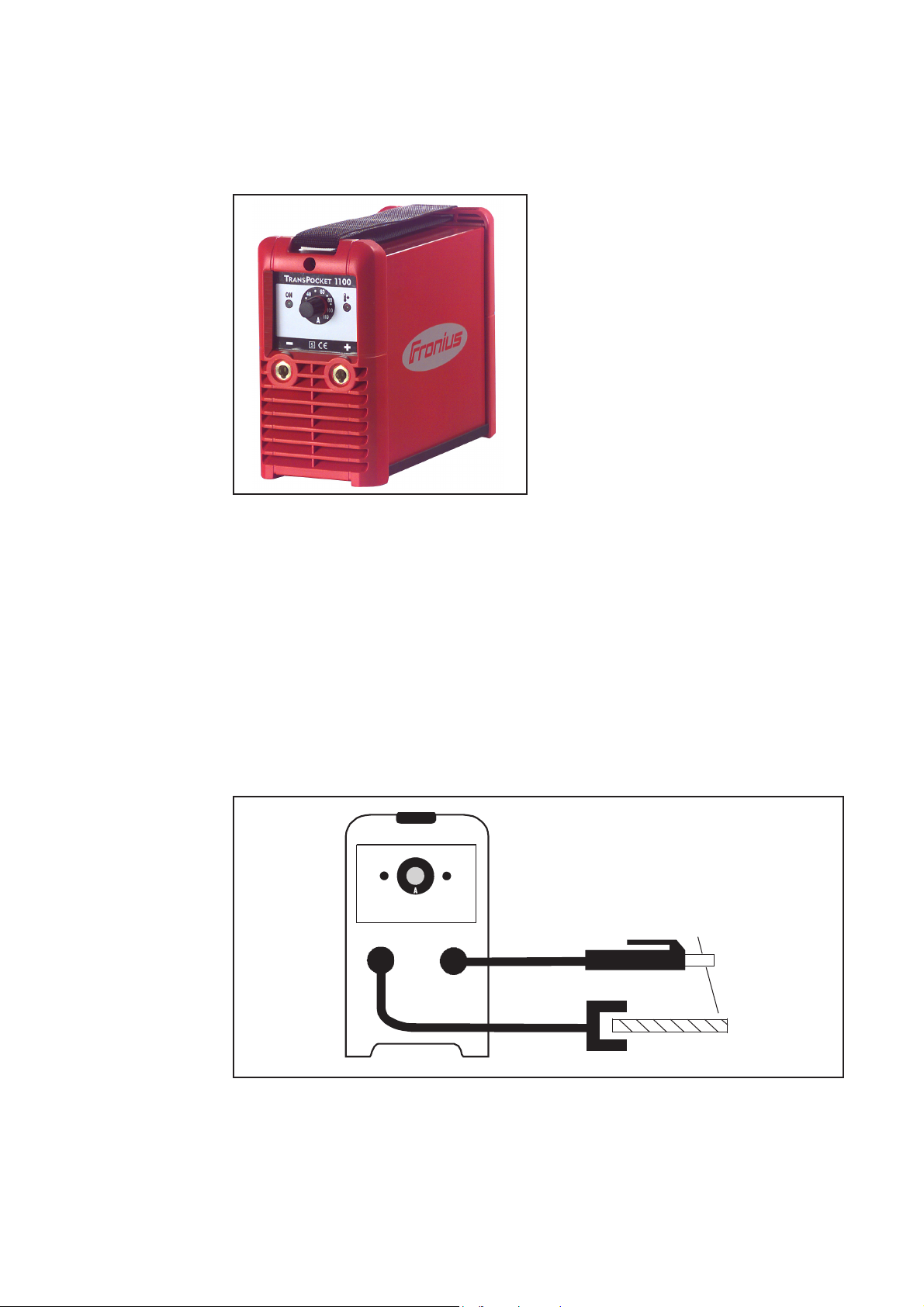
General remarks
Principle
Fig.1 TransPocket 1500 welding unit
An electronic controller adjusts the power-source characteristic to the electrode that is to
be welded.
Machine concept The TP 1100 / 1200 power source may all only be small, but they are built to function
dependably under even the toughest operating conditions. Features such as its powdercoated sheet-steel housing, the way its controls are protected by a plastic frame, and its
bayonet-latching connection sockets all testify to the high quality of its design. Thanks to
its carrying strap, the machine is easy to move around - both in the workshop and out in
the field.
The TP 1100 / TP 1200 power source is a
further member of the new generation of
welding rectifiers. High-performance
electronics have helped create a truly
unique rectifier that weighs in at a mere
4.7 kg.
The TP 1100 / TP 1200 works on the
principle of the resonance inverter. The
voltage from the mains is first rectified.
The resulting DC voltage is then inverted,
at a frequency of up to 150 kHz. The
welding transformer then creates the
required operating voltage, which is
rectified and delivered to the output
sockets.
Areas of use
Fig.2 TP 1100 / TP 1200 tooled up for rod electrode welding
2
Page 47

Warning! Operating the equipment incorrectly can cause serious injury or
damage.Do not use the functions decribed here until you have read and completely understood all of the following documents:
- these Operating Instructions
- all „Operating Instructions“ for the system components, especially the
„Safety rules“
Controls and connections
Operating panel
EN
Connections
(5) (6) (7)
Fig.3 TP 1100 power source: Controls and
indicators on the operating panel
(5) Operational readiness indicator ...
lights up when the mains switch is
shifted to “1”
(6) Welding current dial ... for conti-
nuous adjustment of the welding
current
(7) Malfunction indicator ... lights up
when the unit is thermally overloaded
(i.e. overheats)
(1)
(4)
(3)
Fig.4 Front view and rear view of TP 1100
(1) Mains switch
(2) Dust filter (option) ... in the air-intake zone of the fan
- prevents the inside of the housing from getting soiled in heavily dust-laden
environments
(3) - Current socket with bayonet latch ... for connecting:
- rod-electrode or earthing cable for rod-electrode welding (depending on type of
electrode)
(4) - Current socket with bayonet latch ... for connecting:
- rod-electrode or earthing cable for rod-electrode welding (depending on type of
electrode)
3
(2)
Page 48

Before putting the power source into service
Warning! Operating the equipment incorrectly can cause serious injury or
damage.Do not use the functions decribed here until you have read and completely understood all of the following documents:
- these Operating Instructions
- all „Operating Instructions“ for the system components, especially the
„Safety rules“
Warning! A machine that topples over or falls from its stand can easily kill
someone. Place equipment on an even, firm floor in such a way that it stands in
a stable way.
Safety
Utilisation for
intended purpose
only
Machine set-up
regulations
The power source is intended to be used SOLELY for rod electrode welding.
Any other use, or any use going beyond the above, is deemed to be “not for the intended
purpose” and the manufacturer shall not be liable for any damage resulting therefrom.
"Utilisation for the intended purpose" shall also be deemed to encompass:
- the observance of all instructions in the operating manual
- the carrying out of all prescribed inspection and maintenance work
The power source is tested to “Degree of protection IP23”, meaning:
- Protection against penetration by solid foreign bodies with diameters larger than
12,5 mm (.49 in.)
- Protection against spraywater up to an angle of 60° to the upright
The welding machine can be set up and operated outdoors in accordance with IP23.
However, the built-in electrical components must be protected against direct wetting.
The venting duct is a very important safety feature. When choosing the machine location, make sure that it is possible for the cooling air to enter and exit unhindered through
the louvers on the front and back of the machine. Any metallic dust from e.g. grindingwork must not be allowed to get sucked into the machine.
Mains connection
The equipment is designed to run on the mains voltage given on the respective rating
plates.
230 V~
-15%
Fig.5 Tolerance ranges of the mains voltage
The power source can be run as standard on a mains voltage of 230 V~ (+/- 15%).
Thanks to its +/-15% tolerance range, it can also be run on the 220 V~ or 240 V~ mains.
Note! If the power source is run on the wrong mains voltage, all warranty rights
will be forfeited!
4
265 V~195 V~
+15%
Page 49

Mains connection
Warning! An electric shock can be fatal. If the machine is plugged into the
mains electricity supply during installation, there is a high risk of very serious
injury and damage. Only carry out any work on the machine if
- the mains switch is in the „O“ position, and
- the machine is unplugged from the mains
Warning! Operating the equipment incorrectly can cause serious injury or
damage.Do not use the functions decribed here until you have read and completely understood all of the following documents:
- these Operating Instructions
- all „Operating Instructions“ for the system components, especially the
„Safety rules“
Caution! Risk of injury and damage from electric shock. As soon as the mains
switch is in the „I“ position, the rod elctrode in the electrode holder is LIVE.
Make sure that the rod electrode does not touch any persons or electrically
conducting or earthed parts (e.g. the housing etc.)
(continued)
If your version of the machine does not come with the mains cables and plugs readymounted, these must be mounted in accordance with your national regulations and
Standards. For details of fuse protection of the mains supply lead, please see the Technical Data.
Note! Inadeqately dimensioned electrical installations can lead to serious
damage. The mains supply lead, and its fuse protection, must be dimensioned
accordingly. The technical data shown on the rating plate shall apply.
The TP 1100 and TP 1200 are completely suitable for being run on generator power,
provided that the apparent power delivered by the generator is at least 10 kVA.
Rod electrode welding
Safety
EN
Preparation
Set the welding
amperage, ignite
the arc
- Plug the welding cable into current socket (3) or (4), depending on the type of
electrode, and turn it clockwise to latch it
- Plug the machine into the mains
- Shift the mains switch (1) into the "I" position
- Select the amperage with the welding-current dial (6)
- Start welding
5
Page 50

Hot Start function
I (A)
120A
90A
Advantages:
- Improved ignition, even when using
electrodes with poor ignition properties
- Better fusion of the base metal in the
start-up phase, meaning fewer coldshut defects
- Largely prevents slag inclusions
Anti-Stick function
0,5 s 1 s 1,5 s
Fig.6 Example of "Hot Start" function
t
Mode of functioning:
For a 0.5 sec duration, the welding current is increased to a certain value. This value is
one third higher than the pre-set welding current (Fig.6)
Example: A welding current of 90 A has been set on the setting dial. The Hot-Start
current will be 90 A + (90 A / 3) = 120 A
Important! In cases where the pre-set welding current is 105 A or above, the Hot-Start
current is limited to 140 A.
When the length of the arc is shortened, the welding voltage may drop so far that the rod
electrode starts to stick.
Burn-out is prevented by the Anti-Stick function. If the rod electrode begins to stick, the
power source switches the welding current off after 1.5 seconds. After the rod electrode
has been lifted from the workpiece, the welding operation can be resumed without
difficulty.
6
Page 51

Warning! An electric shock can be fatal. Before opening the machine:
- Shift the mains switch into the „O“ position
- Unplug the machine from the mains
- Put op an easy-to-understand warning sign to stop anybody inadvertently
switching it back on again
- Using a suitable measuring instrument, check to make sure that electrically charged components (e.g. capacitors) have been discharged.
Warning! Inadequate PE conductor connections can cause serious injury and
damage. The housing screws provide a suitable PE conductor connection for
earthing (grounding) the housing and must NOT be replaced by any other
screws which do not provide a reliable PE conductor connection.
Troubleshooting
Safety
EN
Troubleshooting
TP 1100, TP 1200
No welding current
Mains switch is ON, operational readiness indicator is not lit up
Cause: Break in mains lead
Remedy: Check mains lead and mains voltage
No welding current
Mains switch is ON, operational readiness indicator is lit up
Cause: Break in welding cable connection
Remedy: Check plug-in connections
Cause: Faulty or broken earth connection
Remedy: Earth workpiece
No welding current
Mains switch is ON, operational readiness indicator is lit up, malfunction indicator is lit up
Cause: Maximum duty cycle exceeded - machine overloaded - fan is running
Remedy: Observe duty cycle
Cause: Thermostatic cut-out system has tripped - fan is running; temperature
sensor is faulty
Remedy: Wait until cooling down period is over, machine will switch on automatically
- if not: machine should be serviced
Cause: Insufficient cooling air reaching machine
Remedy: Ensure sufficient supply of cooling air
Cause: Dust filter (option) is dirty
Remedy: Clean the dust filter (option)
Cause: Power module is very dirty
Remedy: Remove cover of machine and clean out with compressed air (see "Care
and Maintenance")
7
Page 52

Troubleshooting
TP 1100, TP 1200
(continued)
No welding current
Mains switch is ON, operational readiness indicator is lit up, malfunction indicator flashes
Cause: Fault in power module
Remedy: Switch machine off and back on again; if the error keeps on occurring -
send machine in for service
No welding current
After the machine is switched on, all indicators are permanently lit up (longer than 2
seconds)
Cause: Short-circuit (secondary side)
Remedy: Stop the short-circuit (disconnect the rod-electrode cable or earthing
cable from the current socket with the bayonet latch. If the error keeps on
occurring - send machine in for service
Arc sometimes breaks during welding
Cause: Arc-burning voltage of electrode too high (e.g. grooved electrode)
Remedy: If possible, use different type of electrode or a machine capable of deliver-
ing greater welding current
Cause: Mains undervoltage
Remedy: Measure mains voltage on machine, increase the cross-sectional area of
the supply lead
Mains fuse and/or safety cut-out has tripped
Cause: Mains fuse too weak; incorrect safety cut-out
Remedy: Insert correct fuse (see technical data)
Cause: Mains fuse is tripped under no-load conditions
Remedy: Machine should be serviced
Loud bang
in some cases the mains fuse or automatic circuit-breaker is tripped as well
Cause: Varistor (overvoltage protector) has been tripped; mains voltage error
Remedy: Replace the varistor - may only be done by skilled, trained personnel -
otherwise send machine to After-Sales Service
8
Page 53

Care, maintenance and disposal
Warning! An electric shock can be fatal. Before opening the machine:
- Shift the mains switch into the „O“ position
- Unplug the machine from the mains
- Put op an easy-to-understand warning sign to stop anybody inadvertently
switching it back on again
- Using a suitable measuring instrument, check to make sure that electrically charged components (e.g. capacitors) have been discharged.
General remarks
Every start-up
Under normal operating conditions the power source requires only a minimum of care
and maintenance. However, it is indispensable to follow some important points to ensure
the operationality of the welding machine for many years.
- Check mains cable, mains plug, rod-electrode cable and bondings for damage
- Check whether the allround distance of 0.5 m (1ft. 8in.) is kept to ensure that the
cooling air can easily flow and escape.
Note! Furthermore, air inlets and outlets must in no case be covered, not even
covered partly.
EN
Every 2 months
Every 6 months
Disposal
- Optional: clean air filter
- Dismantle machine side panels and clean machine inside with dry reduced compressed air.
Note! Risk of damage to electronical components. Clean electronical componenets from a certain distance only.
- If a lot of dust has accumulated, clean the cooling-air ducts.
Carry out disposal in accordance with the valid national and local regulations.
9
Page 54

Technical Data
TP 1100
Mains voltage 230 V
Mains voltage tolerance ± 15 %
Power frequency 50 / 60 Hz
Mains fuse protection 16 A slow
Grid connection
1)
Restrictions possible
Primary continuous current (100 % d.c. 2)) 6.93 A
Primary continuous power 1.58 kVA
Cos Phi (110 A) 0.99
Degree of efficiency (60 A) 85 %
Welding current range 10 - 110 A
Welding current at 10 min / 25°C (104°F)30 % d.c.
100 % d.c.
10 min / 40°C (104°F)20 % d.c.
100 % d.c.
2)
2)
2)
2)
110 A
80 A
110 A
60 A
Welding voltage range according to standard characteristic 20.4 -24.4 V
Max. welding voltage 24.63 V
Open-circuit voltage 105 V
Degree of protection IP 23
EMC emission class A
(according to EN/IEC 60974-10)
Mark of conformity CE
Safety designation S
1) To 230/400 V, 50 Hz public supply grids
2) d.c. = duty cycle
10
Page 55

TP 1200
Mains voltage 230 V
Mains voltage tolerance ± 15 %
Power frequency 50 / 60 Hz
Mains fuse protection 16 A slow
Grid connection
Primary continuous current (100 % d.c. 2))8 A
1)
Restrictions possible
EN
Primary continuous power 1.9 kVA
Cos Phi (120 A) 0.99
Degree of efficiency (60 A) 85 %
Welding current range 10 - 120 A
Welding current at 10 min / 40°C (104°F)15 % d.c.
60 % d.c.
100 % d.c.
2)
2)
2)
120 A
50 A
40 A
Welding voltage range according to standard characteristic 20.4 -24.8 V
Max. welding voltage 24.8 V
Open-circuit voltage 105 V
Degree of protection IP 23
EMC emission class A
(according to EN/IEC 60974-10)
Mark of conformity CE
Safety designation S
1) To 230/400 V, 50 Hz public supply grids
2) d.c. = duty cycle
11
Page 56

12
Page 57

Cher lecteur
Introduction
Nous vous remercions de votre confiance et vous félicitons d’avoir acheté un produit de
qualité supérieure de Fronius. Les instructions suivantes vous aideront à vous familiariser avec le produit. En lisant attentivement les instructions de service suivantes, vous
découvrirez les multiples possibilités de votre produit Fronius. C’est la seule manière
d’exploiter ses avantages de manière optimale.
Prière d’observer également les consignes de sécurité pour garantir une sécurité accrue
lors de l’utilisation du produit. Une utilisation soigneuse du produit contribue à sa longévité et sa fiabilité. Ce sont des conditions essentielles pour obtenir d’excellents résultats.
FR
ud_fr_st_et_00500 01/2012
Page 58

Page 59

Consignes de sécurité
DANGER!
AVERTISSEMENT!
ATTENTION!
REMARQUE!
Important!
«DANGER!» caractérise un péril immédiat. S’y exposer entraîne la mort ou
des blessures graves.
«AVERTISSEMENT» caractérise une situation pouvant s’avérer dangereuse. S’y exposer peut entraîner la mort et des blessures graves.
«ATTENTION!» caractérise une situation pouvant s’avérer néfaste. S’y
exposer peut entraîner des blessures légères ou minimes ainsi que des
dégâts matériels.
«REMARQUE» caractérise un danger entraîné par une gêne des conditions
de travail et des dégâts possibles sur l’équipement.
«Important» caractérise des conseils d’utilisation et d’autres informations particulièrement utiles. Ne signale pas de situation néfaste ou dangereuse.
Dans le cas où vous rencontreriez l’un des symboles représentés à la lecture du chapitre
«Consignes de sécurité», vous devriez y porter une attention accrue.
FR
Généralités
L’appareil répond aux derniers développements techniques et satisfait à la
réglementation généralement reconnue en matière de sécurité. En cas de
fausse manoeuvre ou de mauvaise utilisation, elle présente toutefois certains risques
- pour la santé et la vie de l‘utilisateur ou d‘un tiers,
- pour la source de courant et pour d‘autres biens matériels de l‘exploitant,
- liés à la qualité du travail effectué avec la source de courant.
Toutes les personnes intervenant dans la mise en service, la manipulation et
l‘entretien de la source de courant doivent
- avoir la qualification requise,
- avoir des connaissances suffisantes en soudure et
- observer scrupuleusement les instructions de service.
Les instructions de service doivent être conservées en permanence sur le
lieu d‘utilisation de l’appareil. En complément aux instructions de service, la
réglementation généralement valable et la réglementation locale concernant
la prévention d‘accidents et la protection de l‘environnement doivent à tout
moment être disponibles et respectés.
Toutes les consignes de sécurité et les avertissements de danger apposés
sur l’appareil
- doivent rester lisibles
- ne doivent pas être endommagés
- ne doivent pas être retirés
- ne doivent pas être recouverts, masqués par des autocollants ou peints.
Vous trouverez les emplacements où figurent les consignes de sécurité et
les avertissements de danger sur l’appareil en consultant le chapitre «généralités» du manuel d’instructions de ce dernier.
I
ud_fr_st_sv_00468 022013
Page 60

Généralités
(suite)
Tout dérangement pouvant nuire à la sécurité doit être éliminé avant de
mettre en marche l’appareil.
Votre sécurité est en jeu !
Uilisation conforme
L’appareil a été conçue exclusivement pour une utilisation de le cadre des
travaux prévus.
L’appareil est exclusivement conçu pour les procédés de soudage indiqués
sur la plaque signalétique.
Toute autre utilisation est considérée comme non conforme. Le fabricant ne
saurait par conséquent être tenu responsable des dégâts consécutifs.
Font également partie de l’utilisation conforme:
- la lecture exhaustive et l’observation de toutes les indications du manuel
d’instructions de service
- la lecture exhaustive et le respect des consignes de sécurité et des
avertissements de danger du manuel d’instructions de service
- le respect des travaux d’inspection et d’entretien
Ne jamais utiliser l’appareil pour les applications suivantes:
- Dégel de tuyaux
- Chargement de batteries/accumulateurs
- Démarrage de moteurs
L’appareil est conçu pour le fonctionnement dans l’industrie et l’artisanat. Le
fabricant ne saurait être tenu responsable des dommages consécutifs à
l’utilisation de l’appareil dans une habitation.
Le fabricant n’endosse aucune responsabilité pour des résultats de travail
laissant à désirer ou défectueux.
Conditions
environnementales
Obligations de
l‘exploitant
La marche ou le stockage de l’appareil en dehors de la zone indiquée est
considéré comme impropre. Le fabricant ne saurait être tenu responsable
de dommages en résultant.
Plage de température de l’air environnant:
- pour le service: - 10 °C à + 40 °C (14 °F à 104 °F)
- pour le transport et le stockage: - 20 °C à + 55 °C (-4 °F à 131 °F)
Humidité de l’air relative:
- jusqu’à 50 % à 40 °C (104 °F)
- jusqu’à 90 % à 20 °C (68 °F)
’air environnant doit être dénué de poussières, d’acide, de gaz ou de substances corrosives, etc.
Altitude au-dessus du niveau de la mer: jusqu’à 2000m (6500 ft)
L‘exploitant s‘engage à n‘autoriser l‘utilisation de l’appareil qu‘à des personnes
- connaissant les prescriptions fondamentales concernant la sécurité du
travail et la prévention d‘accidents et familiarisées avec la manipulation
de l’appareil
- ayant lu et compris le mode d’emploi, en particulier le chapitre « Consignes de sécurité » et l‘ont confirmé par leur signature.
- ayant reçu une formation conforme aux exigences adressées par les
résultats demandés
ud_fr_st_sv_00468 022013
Il convient de vérifier à intervalles réguliers que le personnel est conscient
des consignes de sécurité pendant le travail.
II
Page 61
Obligations du
personnel
Toutes les personnes chargées de travailler avec l’appareil s‘engagent à
- respecter les prescriptions fondamentales en matière de sécurité du
travail et de prévention des accidents,
- lire les instructions de service, en particulier le chapitre « Consignes de
sécurité » et à attester par leur signature qu‘ils les ont compris, ceci
avant d‘entamer le travail.
Avant de s’éloigner du poste de travail, s’assurer de l’impossibilité de la
survenue de dégâts matériels ou corporels pendant cette absence.
Raccordement au
secteur
Auto-protection
et protection des
personnes
En raison de leur absorption de courant élevée, les appareils de forte
puissance influent sur la qualité énergétique du réseau d’alimentation.
Certains types d’appareils peuvent être touchés sous la forme :
- de restrictions de raccordement
- d’exigences relatives avec l’impédance maximale autorisée du secteur
- d’exigences relatives à la puissance de court-circuit nécessaire
*)
à l’interface avec le réseau public
*)
voir caractéristiques techniques
Dans ce cas, l’exploitant ou l’utilisateur de l’appareil doit s’assurer que
l’appareil peut être raccordé au réseau, au besoin en prenant contact avec
le distributeur d’électricité.
REMARQUE Il faut veiller à la bonne mise à la terre du couplage
au réseau.
Vous vous exposez à de nombreux dangers pendant le soudage, comme
par ex.
- projection d’étincelles et de pièces métalliques incandescentes
- rayonnement de l’arc lumineux nocif pour la peau et les yeux
FR
*)
- champs éléctromagnétiques synonymes de danger de mort pour les
porteurs de stimulateur cardiaque (pacemaker)
- danger d’électrocution en raison du courant secteur et de soudage
- nuisance du bruit
- fumée et gaz de soudage nocifs
Les personnes travaillant sur la pièce à usiner pendant le soudage doivent
porter des vêtements de protection présentant les caractéristiques suivantes:
- difficilement inflammables
- isolants et secs
- couvrant l’ensemble du corps, non endommagés et en bon état
- casque de protection
- pantalon sans ourlet
III
ud_fr_st_sv_00468 022013
Page 62

Auto-protection
et protection des
personnes
(suite)
Font entre autre partie des vêtements de protection:
- Protégez les yeux et la face des rayons ultraviolets , de la chaleur et de
la projection d’étincelles en utilisant un écran de soudeur doté de verres
filtrants réglementaires.
- Porter des lunettes de protection conformes à la règlementation derrière
l’écran de soudeur
- Portez des chaussures solides, isolantes. Ces chaussures doivent
rester isolantes même dans un environnement humide
- Protégez les mains par des gants appropriés (isolants électriques,
protection thermique
- Porter un casque antibruit pour réduire les nuisances liées au bruit et
pour éviter de vous endommager les tympans.
Tenir éloignées toutes personnes étrangères et surtout les enfants pendant
la marche des appareils et le processus de soudage. S’il y avait toutefois
des personnes à proximité:
- les informer de l’ensemble des dangers (danger d’éblouissement par
l’arc lumineux, danger de blessures par la projection d’étincelles, gaz de
fumée toxiques, danger lié au courant secteur ou de soudage,...)
- mettre à leur disposition les moyens de protection adéquats ou
- mettre en place des cloisons ou des rideaux de séparation.
Données relatives aux valeurs
des émissions
sonores
Risque provenant du dégagement de vapeurs et gaz
nocifs
L’appareil émet un niveau de puissance acoustique < 80 dB(A) (réf. 1pW)
en marche à vide ainsi que dans la phase de refroidissement après fonctionnement au point de travail maximal autorisé en charge normale, conformément à la norme EN 60974-1.
Une valeur d’émission rapportée au poste de travail ne peut pas être indiquée pour le soudage (et le découpage) car celle-ci est fonction du procédé
utilisé et de l’environnement. Elle dépend de paramètres les plus divers
comme p. ex. du procédé de soudage (MIG/MAG, TIG), du type de courant
choisi (continu, alternatif), de la plage de puissance, de la nature du métal
fondu, du comportement à la résonance de la pièce à usiner, de
l’environnement du poste de travail, etc.
La fumée dégagée pendant le soudage contient des gaz et des vapeurs
toxiques.
La fumée dégagée pendant le soudage contient des substances éventuellement tératogènes ou cancérogènes.
Maintenir la tête à l’écart de la fumée et des gaz de soudage.
- ne pas respirer la fumée dégagée et les gaz toxiques
- les évacuer du lieu de travail par des moyens appropriés.
ud_fr_st_sv_00468 022013
Veiller à un apport d’air frais suffisant.
En cas d’aération insuffisante, porter un masque respiratoire alimenté en air.
Quand on ignore si la puissance d’aération est suffisante, comparer les
valeurs d’émission des substances toxiques aux valeurs seuil admissibles.
Fermer le robinet de la bouteille de gaz de protection ou fermer
l'alimentation centrale en gaz si aucun soudage n'est en cours.
IV
Page 63

Risque provenant du dégagement de vapeurs et gaz
nocifs
(suite)
Les composantes suivantes sont entre autres responsables du degré de
toxicité de la fumée de soudage:
- métaux employés pour la pièce à usiner
- électrodes
- revêtements
- Détergents, solvants à dégraisser et autres
Pour cette raison, tenir compte des fiches techniques sur la sécurité et des
indications du fabricant des composants énumérés.
Tenir les vapeurs inflammables (par ex. vapeurs de solvants) à l’écart de la
zone de rayonnement de l’arc lumineux.
FR
Risques provenant de la
projection
d‘étincelles
Risques provenant du courant secteur et du
courant de
soudage
La projection d’étincelles peut causer des incendies et des explosions.
Ne jamais souder à proximité de matériaux inflammables.
Les matériaux inflammables doivent être éloignés d’au moins 11 mètres (36
ft. 1.07 in.) de l’arc lumineux ou recouverts d’une feuille homologuée.
Garder des extincteurs appropriés à portée de main.
Les étincelles et les pièces métalliques incandescentes peuvent parvenir
dans la zone environnante à travers les fentes et ouvertures. Prendre des
mesures appropriés pour pallier à tout danger de blessure et d’incendie.
Ne pas souder dans des zones menacées d’incendie ou d’explosion ou sur
des réservoirs, barrils ou tuyaux fermés, à moins d’avoir fait des préparatifs
conformes aux normes nationales et internationales.
Il est interdit de souder sur des réservoirs contenant ou ayant contenu des
gaz, des carburants, des huiles minérales et substances analogues. Même
des résidus de ces substances présentent un risque d‘explosion.
Une décharge électrique est fondamentalement dangereuse et peut être
mortelle.
Ne pas toucher les éléments conducteurs de tension à l’intérieur et à
l’extérieur de l’appareil.
Pour le soudage MIG/MAG et TIG, le fil-électrode, la bobine, les rouleaux
d’entraînement et les pièces métalliques liés au fil-électrode sont conducteurs de tension.
Toujours poser l’unité d’entraînement du fil-électrode sur un fond suffisamment isolé ou utiliser un logement isolant approprié pour l’avance de fil.
Veiller à une auto-protection et à la protection des personnes appropriées
en mettant un support ou une feuille plastique secs, suffisament isolants
face au potentiel de terre ou de masse. Le support ou la feuille plastique
doit recouvrir l’ensemble de la zone située entre le corps et le potentiel de
terre ou de masse.
Tous les câbles et lignes doivent être solides, intacts, isolés et présenter les
dimensions suffisantes. Remplacer immédiatement les liaisons desserrées,
les câbles et lignes grillés, endommagés ou sous-dimensionnés.
V
ud_fr_st_sv_00468 022013
Page 64

Risques provenant du courant secteur et du
courant de
soudage
(suite)
Ne pas enrouler de câbles ou lignes autour du corps ou de membres.
- ne jamais plonger dans l’eau l’électrode de soudage (électrode à baguette, électrode en tungstène, fil-électrode,...) pour la refroidir
- ne jamais toucher l’électrode quand la source de courant est allumée
La double tension de marche à vide peut par exemple survenir entre les
électrodes de soudage d’un appareil. Toucher simultanément les potentiels
des deux électrodes peut être mortel.
Faire vérifier régulièrement par un électricien professionnel le conducteur de
terre de la ligne d‘alimentation secteur et la ligne d‘alimentation de l‘appareil.
N’exploiter l’appareil que sur un réseau muni de conducteur de protection et
une prise de courant avec contact de conducteur de protection.
Est considéré comme négligence grave le fait d’exploiter l’appareil sur un
réseau sans conducteur de protection ou une prise de courant sans contact
de conducteur de protection. Le fabricant n’est pas responsable des dommages consécutifs.
Au besoin, veiller à une mise à terre suffisante de la pièce à usiner par des
moyens appropriés.
Mettre hors d’état de marche les appareils non employés.
Courants de
soudage vagabonds
Pour les travaux en hauteur, utiliser un harnais de sécurité afin d’éviter les
chutes.
Mettre hors d’état de marche l’appareil et tirer la fiche secteur avant les
travaux sur l’appareil.
Prévenir un branchement de la fiche secteur et une nouvelle mise en marche au moyen d’un panneau d’avertissement clair et bien lisible.
Après avoir ouvert l’appareil:
- décharger tous les composants stockant des charges électriques
- s’assurer que toutes les composantes de l’appareil sont hors tension.
Au cas où des interventions sur des éléments sous tension seraient nécessaires, il est indispensable de faire appel à une seconde personne qui
puisse, le cas échéant, couper l‘alimentation électrique.
En cas de non-respect des indications ci-après, l’apparition de courants de
soudage vagabonds est possible. Cette dernière peut entraîner:
- le danger d’incendies
- la surchauffe de composants liés à la pièce à usiner
- la destruction des conducteurs de protection
- l’endommagement de l’appareil et d’autres installations électriques
ud_fr_st_sv_00468 022013
Veiller à une liaison solide de la pince à pièces usinées avec la pièce usinée
Fixer la pince à pièces usinées le plus près possible de l’emplacement à
souder.
Lorsque le fond est conducteur électriquement, mise en place, si possible,
de l’appareil de sorte à l’isoler suffisamment.
En cas d’utilisation de distributeurs de courant, de logements à deux têtes,
etc. observer ce qui suit: l’électrode de la torche/du porte-électrode non
VI
Page 65

Courants de
soudage vagabonds
(suite)
utilisé est conductrice de potentiel également. Veillez à un stockage suffisamment isolant de la torche/du porte-électrode non utilisé.
Pour les applications automatisées MIG/MAG, le cheminement du fil-électrode doit impérativement être isolé entre le fût de fil de soudage, la grande
bobine ou la bobine de fil et le dévidoir.
Classification
CEM des appareils
Mesures relatives
à la CEM
Appareils de la classe d’émissions A :
- ne sont prévus que pour une utilisation dans les zones industrielles
- peuvent entraîner des perturbations de rayonnement liées à leur puis-
sance
Appareils de la classe d’émissions B :
- répondent aux exigences d’émissions pour les zones habitées et les
zones industrielles ainsi que pour les zones habitées dans lesquelles
l’alimentation énergétique s’effectue à partir du réseau public basse
tension
Classification CEM des appareils conformément à la plaque signalétique ou
aux caractéristiques techniques
Dans certains cas, des influences peuvent se manifester dans la zone d’application prévue malgré le respect des valeurs limites d’émissions normalisées (p. ex. en présence d’appareils sensibles sur le site d’installation ou
lorsque ce dernier est situé à proximité de récepteurs radio ou TV).
L’exploitant est alors tenu de prendre les mesures nécessaires pour éliminer
les dysfonctionnements.
Examiner et évaluer tout problème éventuel et la résistance aux pannes des
installations à proximité en fonction des prescriptions nationales et internationales
- Installations de sécurité
- Lignes de réseau, de signalisation et de transmission des données
- Installations informations et de télécommunications
- Dispositifs pour mesurer et calibrer
FR
Mesures auxiliaires pour éviter les problèmes EMV
a) Alimentation du réseau
- Prendre des mesures supplémentaires (utiliser par ex. des filtres de
réseau appropriés) quand des pannes électromagnétiques surviennent
malgré le raccord au réseau conforme aux prescriptions.
b) Lignes de soudage
- doivent être aussi courtes que possible
- doivent être posées à proximité les unes des autres (aussi pour éviter
des problèmes EMF)
- doivent être posées loin d’autres lignes
c) Egalisation de potentiel
d) Mise à la terre de la pièce à usiner
- le cas échéant, réaliser une liaison à la terre moyennant des condensateurs appropriés
e) Protection, au besoin
- protéger les autres installations environnantes
- protéger l’ensemble de l’installation de soudage
VII
ud_fr_st_sv_00468 022013
Page 66

Mesures EMF
Les champs électromagnétiques peuvent se répercuter négativement sur la
santé et avoir des conséquences encore inconnues à ce jour.
- Conséquences sur la santé des personnes avoisinantes, par ex. les
porteurs de pacemakers
- Les porteurs de pacemakers doivent consulter leur médecin avant de
séjourner à proximité immédiate du poste de travail de soudage
- Tenir les distances entre les câbles de soudure et la tête/le tronc du
soudeur aussi grandes que possibles pour des raisons de sécurité
- Ne pas porter les câbles de soudure et les paquets de câbles sur
l’épaule et/ou ne pas les enrouler autour le corps et de parties du corps
Zones particulièrement dangereuses
Tenir les mains, les cheveux, les vêtements et les outils à l’écart des pièces
mobiles, comme par exemple:
- ventilateurs
- roues dentées, rouleaux, arbres
- bobines de fil et fils-électrodes
Ne jamais approcher les doigts des roues dentées du système d‘entraînement du fil lorsqu‘il est en fonctionnement.
Les feuilles plastiques et les parties latérales ne doivent être retirées/
ouvertes que pendant la durée des travaux d’entretien et de réparation.
Pendant la marche:
- S’assurer que tous les recouvrements soient fermés et l’ensemble des
parties latérales correctement montées.
- Maintenir fermés tous les recouvrements et parties latérales.
La sortie du fil-électrode du brûleur représente un danger élevé de blessures (perforation de la main, blessures du visage et des yeux,...).
Pour cette raison, tenir toujours le brûleur éloigné du corps en enfilant le filélectrode (appareils avec dévidoir) et porter des lunettes de protection
adaptées.
ud_fr_st_sv_00468 022013
Ne pas toucher la pièce à usiner pendant et après le soudage - danger de
brûlures!
Des scories peuvent être projetées par les outils en cours de refroidissement. Pour cette raison, porter l’équipement de sécurité conforme aux
prescriptions même pendant les travaux ultérieurs et veiller à ce que les
personnes séjournant à proximité soit protégées.
Laisser refroidir les chalumeaux et les autres éléments de l’équipement à
haute température de service avant de travailler dessus.
Dans les locaux exposés au risque d‘incendie ou d‘explosion, une réglementation particulière est applicable. Respecter la réglementation nationale
et internationale qui s‘y rapporte.
Les sources de courant destinées aux travaux dans des locaux à risques électriques accrus (p. ex. chaudières) doivent être pourvus du label (Safety). La
source de courant ne doit toutefois pas être placée dans de telles pièces.
VIII
Page 67

Zones particulièrement dangereuses
(suite)
Risque d’ébouillantement par la sortie d’agent réfrigérant. Mettre hors
service l’unité de refroidissement avant de débrancher les raccords pour
l’aller ou le retour d’eau.
Pour manipuler le réfrigérant, respecter les indications de la fiche technique
de sécurité du réfrigérant. Vous pouvez demander la fiche technique de
sécurité du réfrigérant auprès de votre service après-vente ou sur la page
d’accueil du fabricant.
N’utiliser que des dispositifs de suspension de charge appropriées du
fabricant pour le transport par grue d’appareil.
- Accrocher les chaînes ou élingues aux points prévus à cet effet du
matériel de suspension des charges.
- Les chaînes ou élingues doivent former l’angle le plus petit possible
d’avec la verticale.
- Retirer la bouteille de gaz et l‘unité d‘entraînement du fil (appareils MIG/
MAG et TIG).
En cas d’accrochage à une grue de l’unité d’entraînement du fil-électrode
pendant le soudage, utiliser toujours un accrochage isolant pour l’unité
d’entraînement du fil-électrode (appareils MIG/MAG et TIG).
Si l’appareil est équipé d’une courroie de transport ou d’une poignée, elle sert
exclusivement au transport à la main. La courroie ne se prête pas au transport par grue, par chariot élévateur ou d’autre outils de levage mécanique.
FR
Problèmes avec
les résultats de
soudage
Tous les moyens d’accrochage (sangles, boucles, chaînes, etc.) utilisés
avec l’appareil ou ses composants doivent être vérifiés régulièrement (p. ex.
dommages mécaniques, corrosion ou modifications dues à d’autres conditions environnementales).
Les intervalles et l’étendue du contrôle doivent répondre au minimum aux
normes et directives nationales en vigueur.
Danger que du gaz protecteur incolore et inodore ne s’échappe en cas
d’utilisation d’un adaptateur sur le raccord à gaz protecteur. Etancher le
filetage de l’adaptateur destiné au raccord du gaz protecteur au moyen
d’une bande en Téflon avant le montage.
Pour un fonctionnement sûr et conforme de l’installation de soudage, respecter
les prescriptions ci-dessous concernant la qualité du gaz de protection :
- Taille des particules solides <40µm
- Point de rosée <-20°C
- Teneur en huile max. <25mg/m³
En cas de besoin, utiliser des filtres.
REMARQUE ! Les conduites en circuit fermé présentent un risque
plus élevé d’encrassement.
Danger par les
bonbonnes de
gaz de protection
Les bonbonnes de gaz de protection contiennent du gaz sous pression et
peuvent exploser en cas d’endommagement. Comme les bonbonnes de gaz
de protection font partie de l’équipement requis pour le soudage, il convient
de les manipuler avec le plus grand soin.
Protéger les bonbonnes de gaz de protection contenant du gaz densifié
d’un excès de chaleur, des coups, des scories, des flammes vives, des
étincelles et des arcs lumineux.
IX
ud_fr_st_sv_00468 022013
Page 68

Danger par les
bonbonnes de
gaz de protection
(suite)
Monter les bonbonnes de gaz de protection à la verticale et les fixer conformément aux instructions pour éviter tout renversement.
Tenir les bonbonnes de protection éloignées des circuits de soudage ou
d’autres circuits de courant électrique.
Ne jamais accrocher un chalumeau à une bonbonne de gaz de protection.
Ne jamais toucher une bonbonne de gaz de protection avec une électrode
de soudage.
Danger d’explosion - ne jamais souder sur une bonbonne de gaz de protection sous pression.
Employer toujours les bonbonnes de gaz de protection convenant à
l’application respective et les accessoires appropriés (régulateurs, flexibles
et raccords,...). N’utiliser que des bonbonnes de gaz de protection et des
accessoires en bon état.
Ecarter le visage de l’échappement à chaque fois qu’on ouvre une bouteille
de gaz de protection.
Fermer la bouteille une fois qu’on a fini de souder.
Laisser le capuchon sur la bonbonne de gaz de protection quand elle n’est
pas raccordée.
Mesures de
sécurité sur le
lieu d‘installation
de l’appareil et
pendant le transport
Se conformer aux indications du fabricant et aux prescriptions nationales et
internationales en matière de bonbonnes de gaz de protection et d’accessoires.
Le renversement de l’appareil présente un grave danger ! L’appareil doit
être installée sur un sol ferme et plat offrant suffisamment de stabilité.
- Un angle d’inclinaison de 10° au maximum est autorisé
Dans les locaux exposés au risque d‘incendie ou d‘explosion, une réglementation particulière est applicable. Respecter la réglementation nationale
et internationale qui s‘y rapporte.
Assurer par des directives et des contrôles internes que l‘environnement du
lieu de travail soit toujours propre et ordonné.
N’installer et n’exploiter l’appareil que conformément au type de protection
indiqué sur la plaque signalétique.
A l’installation de l’appareil, laisser un espace de 0,5 m (1,6 ft) tout autour,
afin que l’air de refroidissement puisse circuler.
Pendant le transport de l’appareil, veiller à ce que les directives nationales
et régionales de prévention des accidents soient respectées, en particulier
celles sur les risques pendant le transport.
ud_fr_st_sv_00468 022013
Avant de transporter l’appareil, vidanger entièrement le fluide réfrigérant et
démonter les composants suivants:
- Dévidoir
- Bobine de fil
- Bouteille de gaz protecteur
Avant la mise la mise en service suivant le transport, effectuer impérativement un contrôle visuel de l’appareil, pour voir s’il est endommagé. Faire
réparer les dommages éventuels par des membres du personnel formés.
X
Page 69

Mesures de
sécurité en
fonctionnement
normal
N‘utiliser l’appareil que si tous les dispositifs de sécurité fonctionnent. En
cas les dispositifs de sécurité ne fonctionnent pas, elle présente toutefois
certains risques
- pour la santé et la vie de l‘utilisateur ou d‘un tiers,
- pour l’appareil et pour d‘autres biens matériels de l‘exploitant,
- liés à la qualité du travail effectué avec l’appareil.
Remettre en état de marche les dispositifs de sécurité défaillants avant la
mise en marche de l’appareil.
Ne jamais contourner ou mettre hors d’état de marche les dispositifs de
sécurité.
S’assurer que personne n’est menacé avant de mettre l’appareil en marche.
- Au moins une fois par semaine, vérifier si l’appareil ne présente aucune
détérioration détectable de l‘extérieur et contrôler le fonctionnement des
dispositifs de sécurité.
- Toujours bien fixer la bonbonne de gaz de protection et la retirer auparavant en cas de transport par grue
- Seul le produit réfrigérant original du fabricant est approprié pour
l’utilisation dans nos appareils en raison de ses propriétés (conduction
électrique, protection antigel, compatiblité avec la pièce à usiner, inflammabilité, ...)
- N’utiliser que le produit réfrigérant original approprié du fabricant
- Ne pas mélanger les produits réfrigérants originaux du fabricant avec
d’autres produits réfrigérants.
- Si des dommages surviennent à l’utilisation d’autres produits réfrigérants, le fabricant ne saurait en être tenu responsable et l’ensemble des
droits à garantie expirent.
- Dans certaines conditions, le produit réfrigérant est inflammable. Ne
transporter le produit réfrigérant que dans des récipients d’origine
fermés et les tenir éloignés de sources d’étincelles.
- Mettre en décharge les produits réfrigérants usagés conformément aux
prescriptions nationales. Votre point de service vous remettra une fiche
de sécurité et/ou par la « Homepage » du fabricant.
- Une fois l’installation refroidie, vérifier le niveau de produit réfrigérant
avant de reprendre le soudage.
FR
Entretien et
réparation
Les pièces d‘autres fabricants n‘offrent pas les garanties de sécurité et de
fonctionnement suffisantes. N‘utiliser que des pièces de rechange ou des
pièces d‘usure d‘origine (s’appliquer également aux pièces standardisées).
Aucune modification, transformation ou montage ne peuvent être effectués
sur l’appareil sans l‘autorisation du constructeur.
Remplacer immédiatement tout composant présentant un défaut quelconque.
Pour toute commande, prière d‘indiquer la dénomination et le numéro de
référence exacts, comme indiqués sur la liste des pièces de rechange, ainsi
que le numéro de série de l’appareil.
XI
ud_fr_st_sv_00468 022013
Page 70

Contrôle technique de sécurité
Le fabricant recommande de faire effectuer au moins tous les 12 mois un
contrôle technique de sécurité de l’appareil.
Au cours de ce même intervalle de 12 mois, le fabricant recommande un
étalonnage des sources de courant.
Un contrôle technique de sécurité réalisé par un électricien spécialisé agréé
est recommandé
- après toute modification
- après montage ou conversion
- après toute opération de réparation, entretien et maintenance
- au moins tous les douze mois.
Pour le contrôle technique de sécurité, respecter les normes et les directives nationales et internationales en vigueur.
Vous obtiendrez des informations plus précises concernant le contrôle
technique de sécurité et le calibrage auprès de votre service après-vente.
Sur demande, ce service tient les documents requis à votre disposition.
Élimination
Marquage de
sécurité
Ne pas jeter cet appareil avec les déchets ménagers ordinaires !
Conformément à la directive européenne 2002/96/CE relative aux déchets
d’équipements électriques et électroniques (DEEE), et à sa transposition
dans la législation nationale, les appareils électriques doivent être collectés
séparément et être soumis à un recyclage respectueux de l’environnement.
Assurez-vous de bien remettre votre appareil usagé à votre revendeur ou
informez-vous sur les systèmes de collecte ou d’élimination locaux approuvés.
Un non-respect de cette directive UE peut avoir des effets néfastes pour
l’environnement et la santé !
Les appareils avec le label CE satisfont aux exigences fondamentales de la
directive en matière de basse tension et de compatibilité électromagnétique
(Par ex. normes significatives en matière de produits de la série de normes
EN 60 974)..
Les appareils avec le label CE satisfont aux exigences des normes correspondantes au Canada et aux Etats-Unis.
Sécurité des
données
Droits d‘auteur
ud_fr_st_sv_00468 022013
L’utilisateur est responsable de la sécurité des données des modifications
apportées aux réglages usine. Le fabricant ne répond pas des réglages
individuels supprimés.
Le fabricant est propriétaire des droits d‘auteurs sur ces instructions de
service.
Le texte et les figures correspondent à l‘état de la technique lors de la mise
sous presse. Sous réserve de modification. Le contenu des présentes
instructions de service ne fondent aucun recours de la part de l‘acheteur.
Nous sommes reconnaissants pour toute proposition d‘amélioration ou
indication d‘erreurs figurant dans les instructions de service.
XII
Page 71

Sommaire
Généralités .................................................................................................................................................... 2
Principe .................................................................................................................................................... 2
Construction de l’appareil ......................................................................................................................... 2
Champs d'application ............................................................................................................................... 2
Eléments de réglage et raccords .................................................................................................................. 3
Panneau de commande ........................................................................................................................... 3
Raccords .................................................................................................................................................. 3
Avant la mise en service ............................................................................................................................... 4
Securité .................................................................................................................................................... 4
Utilisation conforme à la destination prévue ............................................................................................ 4
Consignes concernant l'installation .......................................................................................................... 4
Raccordement au secteur ........................................................................................................................ 4
Soudage à la baguette .................................................................................................................................. 5
Securité .................................................................................................................................................... 5
Préparatifs................................................................................................................................................ 5
Régler le courant de soudage, amorcer l’arc électrique ........................................................................... 5
Fonction "Hot Start".................................................................................................................................. 6
Fonction Anti-Stick ................................................................................................................................... 6
Pannes: Diagnostic et remèdes .................................................................................................................... 7
Securité .................................................................................................................................................... 7
Pannes: Diagnostic TP 1100, TP 1200 ..................................................................................................... 7
Maintenance, entretien et élimination............................................................................................................ 9
Généralités ............................................................................................................................................... 9
À chaque mise en service ........................................................................................................................ 9
Tous le 2 mois .......................................................................................................................................... 9
Tous les 6 mois ........................................................................................................................................ 9
Élimination................................................................................................................................................ 9
Données techniques ................................................................................................................................... 10
TP 1100 .................................................................................................................................................. 10
TP 1200...................................................................................................................................................11
FR
Liste de pièces de rechange
Schema de connexions
Fronius Worldwide
1
Page 72

Généralités
Principe
Construction de
l’appareil
Le TP 1100 / TP 1200 est un membre
supplémentaire de la nouvelle génération
de redresseurs de soudage. L'utilisation
de l’électronique haute performance a
permis la création d'un redresseur exceptionnel de seulement 3,7 kg.
Le TP 1100 / TP 1200 fonctionne sur le
principe d'un convertisseur à résonance.
La tension du courant secteur est redressée. Suit une conversion continu-alternatif
de la tension continue avec une fréquence
de jusqu'à 150 kHz. Après avoir traversé
le transformateur de soudage, la tension
obtenue est la tension de travail désirée
qui est redressée et fournie aux douilles
Fig.1 Soudeuse TP 1100
Un régulateur électronique adapte la caractéristique de la source de courant à
l'électrode de soudage.
Les sources de courant TP 1100 / 1200 sont toutes de petite dimension, mais sont
construites de manière à fonctionner avec fiabilité même dans des conditions
d'utilisation très dures. Le boîtier en tôle thermopoudrée ainsi que les éléments de
commande et les douilles de raccord avec verrouillage à baïonnette sont disposés de
manière à être protégés par le cadre en matière plastique, et répondent ainsi aux plus
hautes exigences. La courroie pratique permet de transporter aisément l'appareil dans
l'usine ou sur le chantier.
de sortie.
Champs
d'application
Fig.2 TP 1100 / TP 1200 équipé pour le soudage à la baguette
2
Page 73

Eléments de réglage et raccords
Avertissement! Les erreurs de manipulation peuvent entraîner des dommages
corporels et matériels graves. N’utilez les fonctions décrites qu’après avoir lu et
compris l’intégralité des documents suivants:
- le présent mode d’emploi
- tous les modes d’emploi des composants du système, en particulier les
consignes de sécurité
Panneau de
commande
(5) (6) (7)
FR
(5) Voyant en ordre de marche ...
allumé lorsque le commutateur
principal est mis sur “1”
(6) Régulateur du courant de soudage
... possibilité de régler en continu le
courant de soudage
(7) Voyant Dérangement allumé lorsque
la température à l'intérieur de
l'appareil est trop élevée
Raccords
Fig.3 La source de courant TP 1100: Eléments de
commande et voyants
(1)
(2)
(4)
(3)
Fig.4 Vue de face / derrière de TP 1100
(1) Interrupteur principal
(2) Filtre antipoussière (option) ...dans la zone d'aspiration du ventilateur
- empêche que l'intérieur du boîtier ne s'encrasse en cas de forte émission de
poussières.
(3) - Prise de courant à verrouillage à baïonnette ... pour raccorder
- le câble de soudage à la baguette ou le câble de mise à la masse lors du soudage à la baguette (suivant le type d'électrode utilisé)
(4) - Prise de courant à verrouillage à baïonnette ... pour raccorder
- le câble de soudage à la baguette ou le câble de mise à la masse lors du soudage à la baguette (suivant le type d'électrode utilisé)
3
Page 74

Avant la mise en service
Avertissement! Les erreurs de manipulation peuvent entraîner des dommages
corporels et matériels graves. N’utilez les fonctions décrites qu’après avoir lu et
compris l’intégralité des documents suivants:
- le présent mode d’emploi
- tous les modes d’emploi des composants du système, en particulier les
consignes de sécurité
Avertissement! Une soudeuse qui se renverse met en danger la vie des
personnes. Installer la soudeuse de manière bien stable sur un sol ferme et
plan.
Securité
Utilisation conforme à la destination prévue
Consignes
concernant
l'installation
La source de courant est destiné exclusivement au soudage à la baguette. Toute utilisation à d'autres fins ne saurait être considérée comme conforme à la destination de
l'appareil. Le constructeur décline toute responsabilité pour les dommages qui résulteraient d'une telle utilisation.
L'utilisation conforme à l'emploi prévu implique également
- l'observation du mode d'emploi et
- la réalisation en temps voulu des travaux d'inspection et d'entretien
La source de courant a été contrôlé en fonction du type de protection IP 23, ceci signifiant :
- protection contre la pénétration de corps étrangers solides supérieurs à ø12,5 mm
(.49 in.)
- protection contre les projections d'eau jusqu’à un angle de 60° par rapport à la
verticale
Comme la soudeuse répond au degré de protection IP23, il peut être installé et fonctionner à l'extérieur. Il est toutefois nécessaire de protéger les éléments électriques incorporés contre l’effet direct de l’humidité.
Le canal de ventilation est un important dispositif de sécurité. Choisir un emplacement
offrant suffisamment d'espace pour que l'air de refroidissement puisse entrer et sortir
librement par les fentes d'air du boîtier de l'appareil. Veiller à ce que la poussière
métallique produite par exemple lors de travaux d'abrasion ne soit pas aspirée directement par le ventilateur de la soudeuse.
Raccordement au
Les appareils sont conçus pour la tension de réseau indiquée sur la plaque signalétique.
secteur
230 V~
-15%
Fig.5 Plages de tolérance de la tension secteur
4
265 V~195 V~
+15%
Page 75

Raccordement au
Avertissement! Un choc électrique peut être mortel. Si l’appareil est branché
sur le réseau pendant l’installation, cela présente des risques de dommages
corpo-rels et matériels graves. Ne faites l’ensemble des travaux préparatoires
que lorsque
- l’interrupteur principal est sur ‘’0’’
- le câble d’alimentation est débranché du réseau
Avertissement! Les erreurs de manipulation peuvent entraîner des dommages
corporels et matériels graves. N’utilez les fonctions décrites qu’après avoir lu et
compris l’intégralité des documents suivants:
- le présent mode d’emploi
- tous les modes d’emploi des composants du système, en particulier les
consignes de sécurité
Attention! Danger de dommages corporels et matériels par choc
électrique.Dés que l’interrupteur principal est en position ‘’I’’, l’électrode en
baguette dans le porte-électrode est conductrice de courant. Veiller à ce que
l’électrode en baguette n’entre en contact ni avec des personnes ni avec des
pièces conductrices ni avec des éléments mis à la terre (par ex. le boîtier).
secteur
(suite)
La source de courant est conçu en standard pour une tension secteur de 230 V~ (+/- 15
%). En raison de la tolérance de +/- 15 %, l'appareil fonctionne également sur un secteur
de 220 V~ ou 240 V~.
Remarque ! Si vous utilisez la mauvaise tension de réseau, vous perdez tout
droit à la garantie.
Si votre modèle d’appareil ne comprend ni câble ni prise d’alimentation, vous devez les
monter en veillant à ce qu’ils correspondent aux normes nationales. Pour les fusibles de
la ligne d’alimentation, reportez-vous aux spécifications techniques.
Remarque: Un installation électrique mal dimensionnée peut être à l’origine de
dommages importants causés sur l’appareil. La ligne d’alimentation et ses
fusibles doivent être dimensionés de manière adéquate. Les spécifications
techniques valables sont celles de la plaque signalétique.
Les sources de courant TP 1100 et TP 1200 peuvent être utilisées sans limitations avec
un générateur si la puissance apparente produite par le générateur s'élève à 10 kVA
minimum.
Soudage à la baguette
Securité
FR
Préparatifs
Régler le courant
de soudage,
amorcer l’arc
électrique
- Schweißkabel je nach Elektrodentype in Strombuchse (3) oder (4) einstecken und
durch Drehen nach rechts verriegeln
- Netzstecker einstecken
- Mettre l'interrupteur principal (1) sur "I"
- Sélectionner l'intensité de courant sur le régulateur du courant de soudage (6)
- Effectuer le soudage
5
Page 76

Fonction "Hot
Start"
I (A)
120A
90A
Avantages :
- Meilleures propriétés d'amorçage,
même avec des électrodes ayant de
mauvaises propriétés d'amorçage
- Meilleure fonte du matériau de base à
la phase de démarrage, donc moins
de points froids
- Excellente prévention des inclusions
de laitiers
Fonction AntiStick
0,5 s 1 s 1,5 s
Fig.6 Exemple de fonction "hot start"
t
Mode de fonctionnement :
Le courant de soudage est augmenté à une valeur définie pendant une demi-seconde.
Cette valeur est d'un tiers supérieure au courant de soudage réglé (fig.6)
Exemple : La valeur réglée sur le régulateur est 90 A . Le courant "hot start" s'éléve alors
à 90 A + (90 A / 3) = 120 A
Important! Si le courant de soudage est réglé à 105 A ou plus, le courant "hot start" est
limité à 140 A.
Lorsque l'arc électrique raccourcit, la tension de soudage peut baisser à tel point que la
baguette commence à coller.
En activant la fonction anti-stick, on peut empêcher cette surchauffe. Lorsque la baguette commence à coller, la source de courant éteint immédiatement l'arrivée de courant au
bout de 1,5 secondes. Une fois la baguette levée de la pièce à souder, le soudage peut
reprendre sans problème.
6
Page 77

Avertissement! Un choc électrique peut être mortel. Avant d’ouvrir l’appareil
- Mettre l’interrupteur principal sur “O“.
- Débrancher la prise secteur
- Placer un écriteau bien lisible et copréhensible sur l’appareil pour que
personne ne le rallume
- S’assurer l’aide d’un appareil de mesure que les composants conducteurs
(condensateurs par ex.) sont déchargés.
Attention! Un raccord de protection insuffisant peut entraîner de graves
dommages corporels et matériels. Les vis du carter sont un raccord de protection approprié pour la mise à la terre du corps de l’appareil. Il ne faut en aucuncas remplacer ces vis par d’autres vis qui n’offriraient pas ce type de connexion
de protection autorisé.
Pannes: Diagnostic et remèdes
Securité
FR
Pannes: Diagnostic TP 1100,
TP 1200
Pas de courant de soudage
Interrupteur principal sur "I", le voyant en ordre de marche n'est pas allumé
Cause: Interruption de la ligne d'alimentation
Remède: Contrôler la ligne d'alimentation et la tension secteur
Pas de courant de soudage
Interrupteur principal sur "I", le voyant en ordre de marche n'est pas allumé
Cause: Interruption des connexions des câbles de soudage
Remède: Vérifier que les câbles sont correctement branchés
Cause: Mise à la masse insuffisante ou interrompue
Remède: Fixer le câble de mise à la masse sur la pièce
Pas de courant de soudage
Interrupteur principal sur "I", le voyant en ordre de marche est allumé, le voyant Défaillance est allumé
Cause: Dépassement de la durée de mise en circuit - surcharge de l'appareil - le
ventilateur marche
Remède: Observer la durée de mise en circuit
Cause: Le coupe-circuit thermique s'est déclenché - le ventilateur marche ; défail-
lance du capteur de température
Remède: Attendre la phase de refroidissement; l'appa-reil se remet en service
automatiquement après peu de temps. Sinon : apporter l'appareil au
service après-vente
Cause: Amenée insuffisante d'air de refroidissement
Remède: Assurer une amenée suffisante d'air
Cause: Filtre antipoussière (option) encrassé
Remède: Nettoyer le filtre antipoussière (option)
Cause: Bloc de puissance fortement encrassé
Remède: Ouvrir l'appareil et purger à l'air comprimé sec (voir maintenance, entreti-
en !)
7
Page 78

Pannes: Diagnostic TP 1100,
TP 1200
(suite)
Pas de courant de soudage
Interrupteur principal sur "I", le voyant en ordre de marche est allumé, le voyant Défaillance clignote
Cause: Défaillance du bloc de puissance
Remède: Déconnecter et reconnecter l'appareil; si le défaut se représente - apporter
l'appareil au service après-vente
Pas de courant de soudage
Après mise en marche, les voyants s'allument et restent tous allumés (plus de 2 secondes)
Cause: Court-circuit (côté secondaire)
Remède: Supprimer le court-circuit (débrancher le câble de la baguette ou le câble
de masse de la prise de courant à baïonnette). Si la défaillance persiste,
apporter l'appareil au service après-vente
Interruption de l'arc pendant le soudage
Cause: Tension de combustion trop élevée de l'élec-trode (p. ex. électrode utilisée)
Remède: Si possible, utiliser une électrode alternative ou un poste de soudage à
puissance de soudage plus élevée
Cause: Sous-tension du secteur
Remède: Mesurer la tension secteur sur l'appareil, augmenter la section transversa-
le de la ligne d'alimentation
Déclenchement du fusible de secteur ou du coupe-circuit automatique
Cause: Protection trop faible du secteur, coupe-circuit ne convient pas
Remède: Assurer un protection convenable du secteur (voir Données techniques)
Cause: Fusible de secteur s'est déclenché en marche à vide
Remède: Apporter l'appareil au service après-vente
Forte détonation
peut-être accompagnée du déclenchement du fusible de secteur ou du coupe-circuit
automatique
Cause: Le varistor s'est déclenché (protection contre les surtensions) - mauvaise
tension de réseau
Remède: Faire changer le varistor - uniquement par le personnel formé ou apporter
l'appareil au service après-vente
8
Page 79

Avertissement! Un choc électrique peut être mortel. Avant d’ouvrir l’appareil
- Mettre l’interrupteur principal sur “O“.
- Débrancher la prise secteur
- Placer un écriteau bien lisible et copréhensible sur l’appareil pour que
personne ne le rallume
- S’assurer l’aide d’un appareil de mesure que les composants conducteurs
(condensateurs par ex.) sont déchargés.
Maintenance, entretien et élimination
Généralités
À chaque mise en
service
La source de courant, lorsqu’elle fonctionne dans des conditions normales, exige un
minimum de maintenance et d’entretien. Il est toutefois indispensable de respecter
certains consignes, pour garder longtemps l’installation de soudage en bon état de
marche.
FR
- Vérifer le câble de réseau, la fiche secteur, le câble de soudage à la baguette et le
raccordement à la terre
- Vérifier si la distance périphérique de 0,5 m (1ft. 8in.) par rapport à l’appareil est
bien respectée, afin que l’air de refroidissement puisse circuler sans problème
Note! D’autre part, les orifices d’amission et de sortie d’air ne peuvent en aucun
cas être recouverts, pas même partiellement.
Tous le 2 mois
Tous les 6 mois
Élimination
- Le cas échéant: nettoyer le filtre à air
- Démonter les parois latérales de l’appareil et nettoyer l’appareil à l’air comprimé
sec, débit réduit.
Note! Risque d’endommagement des composants électroniques. Maintenir une
certaine distance en soufflant l’air comprimé sur ces composants.
- Nettoyer les canaux à air de refroidissement en cas de forte accumulation de
poussière.
Éliminer le réfrigérant conformément aux prescriptions nationales et régionales en
vigueur.
9
Page 80

Données techniques
TP 1100
Tension de réseau 230 V
Tolérance de la tension de réseau ± 15 %
Fréquence du réseau 50 / 60 Hz
Couplage au réseau
1)
Restrictions possibles
Protection par fusibles 16 A à action retardée
Courant permanent primaire (100 % ED 2)) 6,93 A
Puissance permanente primaire 1,58 kVA
Cos Phi (110 A) 0,99
Rendement (60 A) 85 %
Plage de courant de soudage 10 - 110 A
Courant de soudage à 10 min / 25°C (104°F) 30 % ED
100 % ED
10 min / 40°C (104°F) 20 % ED
100 % ED
2)
2)
2)
2)
110 A
80 A
110 A
60 A
Plage de tension de soudage selon la courbe caractéristique normalisée 20,4 -24,4 V
Tension de soudage max. 24,63 V
Tension à vide 105 V
Type de protection IP 23
Classe d’émission CEM A
(selon norme EN/IEC 60974-10)
Marque de conformité CE
Marque de sûreté S
1) Aux réseaux électriques publics 230/400 V et 50 Hz
2) ED = Facteur de marche
10
Page 81

TP 1200
Tension de réseau 230 V
Tolérance de la tension de réseau ± 15 %
Fréquence du réseau 50 / 60 Hz
Protection par fusibles 16 A à action retardée
Couplage au réseau
1)
Restrictions possibles
Courant permanent primaire (100 % ED 2))8 A
Puissance permanente primaire 1,9 kVA
Cos Phi (120 A) 0,99
Rendement (60 A) 85 %
Plage de courant de soudage 10 - 120 A
Courant de soudage à 10 min / 40°C (104°F) 15 % ED
60 % ED
100 % ED
2)
2)
2)
120 A
50 A
40 A
FR
Plage de tension de soudage selon la courbe caractéristique normalisée 20,4 -24,8 V
Tension de soudage max. 24,8 V
Tension à vide 105 V
Type de protection IP 23
Classe d’émission CEM A
(selon norme EN/IEC 60974-10)
Marque de conformité CE
Marque de sûreté S
1) Aux réseaux électriques publics 230/400 V et 50 Hz
2) ED = Facteur de marche
11
Page 82

12
Page 83

Ersatzteilliste
DEENFRITESPT-BRNLNOCSRUSKSVTR
Schaltplan
Spare Parts List
Circuit Diagram
Liste de pièces de rechange
Schéma de connexions
Lista parti di ricambio
Schema
Lista de repuestos
Esquema de cableado
Lista de peças sobresselentes
Esquema de conexões
Onderdelenlijst
Bedradingsschema
Reservdelsliste
Koblingsplan
Seznam náhradních dílù
Schéma zapojení
Список запасных частей
Электрическая схема
Zoznam náhradných dielov
Schéma zapojenia
Reservdelslistan
Kopplingsschema
ud_fr_st_tb_00149 012012
Parça Listesi
Baðlantý þemasý
Czyszczenie palnika
PL
Schemat po³¹czeñ
Page 84

Transpocket 1100 4,075,107
42,0406,0295
45,0200,1087
43,0004,1991
43,0002,0295
41,0001,0632
42,0409,2761
42,0406,0135
4,070,694,Z - LCG
4,100,300
32,0200,9743
LCG
33,0005,4119
43,0006,0153
22,0405,0168
LCA
42,0001,3070
43,0003,0065
22,0405,0261
22,0405,0167
43,0001,1084
4,070,722,Z - LCA11M
41,0001,0627 - Varistor
Transpocket 1100
Ersatzteilliste / Spare parts list / Listes de pièces de rechange / Lista de repuestos / Lista de pecas sobresselentes / Lista dei Ricambi
el_fr_st_eh_00208 012003
1/1
Page 85

Transpocket 1200
Ersatzteilliste / Spare parts list / Listes de pièces de rechange / Lista de repuestos / Lista de pecas sobresselentes / Lista dei Ricambi
el_fr_st_eh_00809 012011
1/1
Page 86

TP 1100, TP 1200
Page 87

Page 88

Page 89

Page 90

FRONIUS INTERNATIONAL GMBH
Froniusplatz 1, A-4600 Wels, Austria
Tel: +43 (0)7242 241-0, Fax: +43 (0)7242 241-3940
E-Mail: sales@fronius.com
www.fronius.com
Under http://www.fronius.com/addresses you will find all addresses
www.fronius.com/addresses
of our Sales & service partners and Locations.
ud_fr_st_so_00082 012011
 Loading...