

Page 1

/ Battery Charging Systems / Welding Technology / Solar Electronics
TR 4000
Bedienungsanleitung
Ersatzteilliste
DEENFR
Fernbedienung
Operating Instructions
Spare Parts List
Remote Control
Instructions de service
Liste de pièces de rechange
Télécommande
42,0410,0919 003-05102012
Page 2

Page 3

Sehr geehrter Leser
DE
Einleitung
Wir danken Ihnen für Ihr entgegengebrachtes Vertrauen und gratulieren Ihnen zu Ihrem
technisch hochwertigen Fronius Produkt. Die vorliegende Anleitung hilft Ihnen, sich mit
diesem vertraut zu machen. Indem Sie die Anleitung sorgfältig lesen, lernen Sie die
vielfältigen Möglichkeiten Ihres Fronius-Produktes kennen. Nur so können Sie seine
Vorteile bestmöglich nutzen.
Bitte beachten Sie auch die Sicherheitsvorschriften und sorgen Sie so für mehr Sicherheit am Einsatzort des Produktes. Sorgfältiger Umgang mit Ihrem Produkt unterstützt
dessen langlebige Qualität und Zuverlässigkeit. Das sind wesentliche Voraussetzungen
für hervorragende Ergebnisse.
ud_fr_st_et_00491 01/2012
Page 4

Page 5

Inhaltsverzeichnis
Fernbedienung TR 4000 ............................................................................................................................... 2
Gerätekonzept ......................................................................................................................................... 2
Systemvoraussetzung ............................................................................................................................. 2
Beschreibung Bedienpanel ...................................................................................................................... 2
Inbetriebnahme ........................................................................................................................................ 4
Fehlerdiagnose und -behebung............................................................................................................... 4
DE
1
Page 6

Fernbedienung TR 4000
Gerätekonzept
Systemvoraussetzung
Die Fernbedienung TR 4000 erlaubt, je
nach Verfahren und Stromquelle, folgende
Einstellungen:
- Umschalten der Parameter
- Einstellen von Schweißleistung /
Schweißstrom
- Einstellen der Lichtbogenlänge /
Hotstart / AC-Frequenz
- Einstellen der Tropfenablöse / Dynamik / Balance
Abb.1 Fernbedienung TR 4000
Die Fernbedienung TR 4000 kann mit allen Stromquellen folgender Serien betrieben
werden:
- TransSynergic 4000 / 5000 / 7200 / 9000
- Transpuls Synergic 2700 / 4000 / 5000 / 7200 / 9000
- TransPocket 2000
- TransTig 2200
- MagicWave 1700 / 2200
Beschreibung
Bedienpanel
Warnung! Fehlbedienung kann schwerwiegende Personen- und Sachschäden
verursachen. Die beschriebenen Funktionen erst anwenden, wenn sowohl die
Bedienungsanleitung für die Fernbedienungen, die Drahtvorschübe und die
Stromquelle vollständig gelesen und verstanden wurde.
(2)
(1)
(1) Taste Parameterumschaltung ... zur
Anwahl und Anzeige folgender
Parameter an der Digitalanzeige:
- Schweißspannung
- Schweißstrom
- Drahtgeschwindigkeit (nur bei
Verfahren MIG/MAG Schweißen)
- Blechdicke (nur bei Verfahren
MIG/MAG Schweißen)
Beim Ändern eines Parameters wird der
Parameterwert zur Kontrolle kurz an der
Digitalanzeige angezeigt.
(2) Einstellregler Schweißleistung /
Schweißstrom ... je nach Verfahren
und Stromquelle mit unterschiedlicher
Funktion belegt:
(3)
Abb.2 Bedienpanel TR 4000
(4)
2
Page 7

Beschreibung
Bedienpanel
(Fortsetzung)
- MIG/MAG Puls-Synergic Schweißen, MIG/MAG Standard-Synergic Schweißen:
Schweißleistung
DE
- MIG/MAG Standard-Manuell Schweißen:
Drahtgeschwindigkeit
- Stabelektroden-Schweißen:
Schweißstrom
- WIG Schweißen:
Schweißstrom
(3) Einstellregler Lichtbogenlängenkorrektur / Hotstart / AC-Frequenz ... je nach
Verfahren und Stromquelle mit unterschiedlicher Funktion belegt:
- MIG/MAG Puls-Synergic Schweißen, MIG/MAG Standard-Synergic Schweißen:
zur Korrektur der Lichtbogenlänge
- .......... kürzere Lichtbogenlänge
0 ......... neutrale Lichtbogenlänge
+ ......... längere Lichtbogenlänge
- MIG/MAG Standard-Manuell Schweißen:
zur Einstellung der Schweißspannung
- Stabelektroden-Schweißen:
beeinflußt den Hotstart (Schweißstrom während der Zündphase)
0 ......... keine Beeinflußung
10 ....... 100%ige Erhöhung des Schweißstromes während der Zündphase
- WIG-AC Schweißen (nur MagicWave 1700/2200):
AC-Frequenz
(4) Einstellregler Tropfenablöse-, Dynamikkorrektur / Dynamik / Balance ... je
nach Verfahren und Stromquelle mit unterschiedlicher Funktion belegt:
- MIG/MAG Standard-Synergic Schweißen:
zur Beeinflussung der Kurzschlußdynamik im Moment des Tropfenüberganges
- .......... härterer und stabilerer Lichtbogen
0 ......... neutraler Lichtbogen
+ ......... weicher und spritzerarmer Lichtbogen
- MIG/MAG Puls-Synergic Schweißen:
stufenlose Korrekturmöglichkeit der Tropfenablöseenergie
- .......... geringere Tropfenablösekraft
0 ......... neutrale Tropfenablösekraft
+ ......... erhöhte Tropfenablösekraft
- Stabelektroden-Schweißen:
zur Beeinflussung der Dynamik (Kurzschlußstromstärke im Moment des Tropfenüberganges)
0 ......... weicher und spritzerarmer Lichtbogen
100 ..... härterer und stabilerer Lichtbogen
- WIG-AC Schweißen (nur MagicWave 1700/2200):
Balance
3
Page 8

Beschreibung
Bedienpanel
(Fortsetzung)
- MIG/MAG Standard-Manuell Schweißen:
zur Beeinflussung der Kurzschlußdynamik im Moment des Tropfenüberganges
0 ......... härterer und stabilerer Lichtbogen
10 ....... weicher und spritzerarmer Lichtbogen
Wichtig! Parameter, die an der Fernbedienung einstellbar sind, können an der Stromquelle nicht geändert werden. Parameteränderungen können nur an der Fernbedienung
erfolgen.
Inbetriebnahme
Fehlerdiagnose
und -behebung
Die Fernbedienung TR 4000 kann sofort nach dem Verbinden des LocalNet Steckers
mit dem LocalNet Anschluß an der Stromquelle betrieben werden.
Die digitalen Stromquellen sind mit einem intelligenten Sicherheitssystem ausgestattet.
Nach der Beseitigung einer möglichen Störung kann die Stromquelle wieder ordnungsgemäß betrieben werden.
Eine genaue Beschreibung von Fehlermeldungen und Angaben zur Beseitigung von
Störungen sind in der Bedienungsanleitung der Stromquelle zu finden.
4
Page 9

Dear Reader
Introduction
Thank you for choosing Fronius - and congratulations on your new, technically highgrade Fronius product! This instruction manual will help you get to know your new
machine. Read the manual carefully and you will soon be familiar with all the many
great features of your new Fronius product. This really is the best way to get the most
out of all the advantages that your machine has to offer.
Please also take special note of the safety rules - and observe them! In this way, you
will help to ensure more safety at your product location. And of course, if you treat your
product carefully, this definitely helps to prolong its enduring quality and reliability - things
which are both essential prerequisites for getting outstanding results.
EN
ud_fr_st_et_00493 01/2012
Page 10

Page 11

Contents
TR 4000 remote-control unit ......................................................................................................................... 2
Appliance concept ................................................................................................................................... 2
System requirements ............................................................................................................................... 2
Description of control panel ..................................................................................................................... 2
Putting the unit into service...................................................................................................................... 3
Troubleshooting ....................................................................................................................................... 3
EN
11
Page 12
TR 4000 remote-control unit
Appliance
concept
System requirements
Depending on the process and type of
power source being used, the following
settings can be made using the TR 4000
remote control unit:
- Switching over the parameters
- Setting the welding power / the
welding current
- Setting the arc length / Hotstart / AC
frequency
- Setting the droplet detachment
dynamic / arc force dynamic /
balance
Fig.1 TR 4000 remote-control unit
The TR 4000 remote-control unit can be operated in conjunction with all the power
sources of the following series:
- TransSynergic 4000 / 5000 / 7200 / 9000
- Transpuls Synergic 2700 / 4000 / 5000 / 7200 / 9000
- TransPocket 2000
- TransTig 2200
- MagicWave 1700 / 2200
Description of
control panel
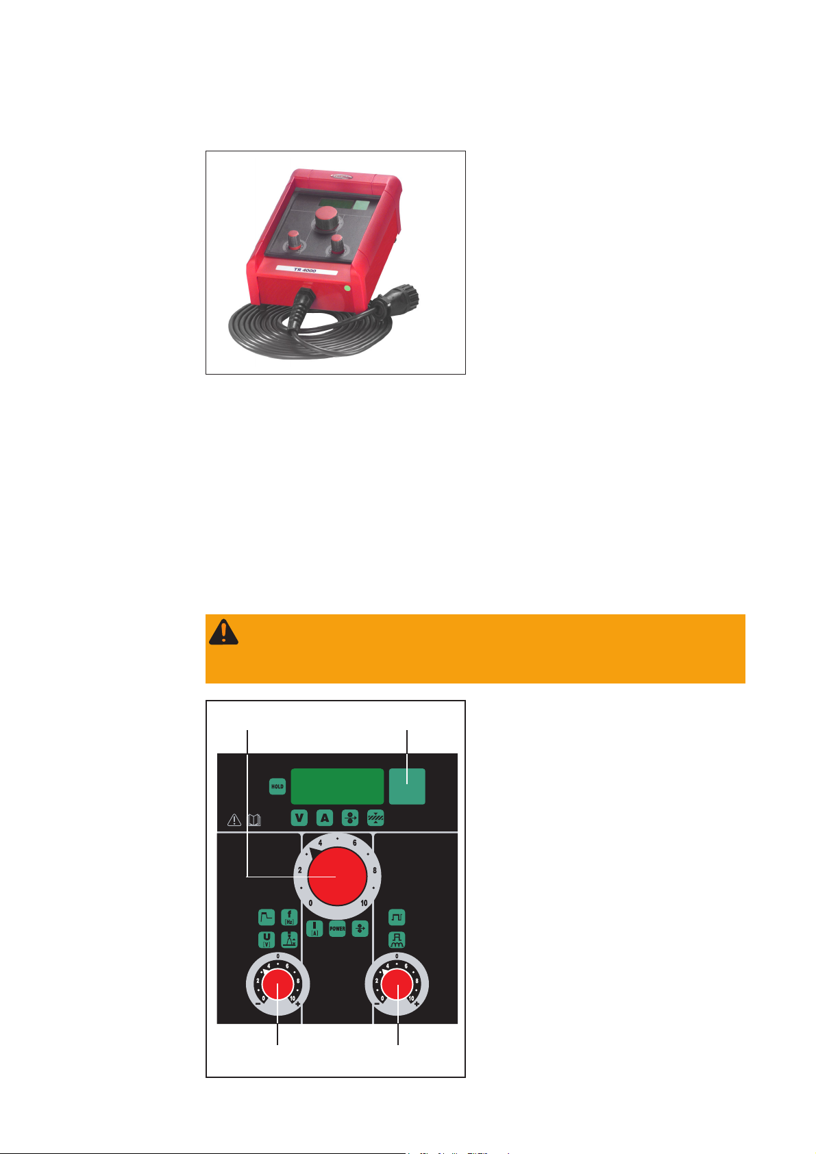
Warning! Operating the unit incorrectly can cause serious injury and damage.
Do not use the functions described here until you have read and completely
understood the whole of the “Operating Instructions” manuals for the remotecontrol units, the wirefeeders and the welding power source.
(1) Parameter switchover button ... for
(2)
(1)
selecting and displaying the following
parameters on the digital display:
- welding voltage
- welding current
- wirefeed speed (only in the MIG/
MAG welding process)
- sheet thickness (only in the MIG/
MAG welding process)
When you change a parameter, the value
for this parameter is briefly indicated - for
control purposes - on the digital display.
(2) Welding power / welding current
dial ... has a different function assigned to it, depending on the process and type of power source being
used:
(3)
Fig.2 TR 4000 control panel
- MIG/MAG pulse-synergic welding,
(4)
22
MIG/MAG standard-synergic
welding:
Welding power
Page 13

Description of
control panel
(continued)
- MIG/MAG standard-manual welding:
Wirefeed speed
- Rod-electrode (MMA) welding:
Welding current
- TIG welding:
Welding current
(3) Arc-length correction, hot-start and AC frequency dial ... has a different
function assigned to it, depending on the process and type of power source being
used:
- MIG/MAG pulse-synergic welding, MIG/MAG standard-synergic welding:
for correcting the arc length
- .......... shorter arc
0 ......... neutral arc length
+ ......... longer arc
- MIG/MAG standard-manual welding:
for setting the welding voltage
- Rod-electrode (MMA) welding:
influences the hot-start (welding current during the ignition phase)
0 ......... no influence
10 ....... 100% increase in the welding current during the ignition phase
- TIG-AC welding (only on MagicWave 1700/2200):
AC frequency
EN
(4) Droplet detachment, arc-force correction, arc-force dynamic and balance dial
... has a different function assigned to it, depending on the process and type of
power source being used:
- MIG/MAG standard-synergic welding:
for influencing the short-circuiting dynamic at the instant of droplet transfer
- .......... harder, more stable arc
0 ......... neutral arc
+ ......... soft, low-spatter arc
- MIG/MAG pulse-synergic welding:
stepless correction facility for droplet-detachment energy
- .......... decreased droplet-detachment force
0 ......... neutral droplet-detachment force
+ ......... increased droplet-detachment force
- Rod-electrode (MMA) welding:
for influencing the arc-force dynamic (short-circuiting amperage at the instant of
droplet transfer)
0 ......... soft, low-spatter arc
100 ..... harder, more stable arc
- TIG-AC welding (only on MagicWave 1700/2200):
Balance
33
Page 14

Description of
control panel
(continued)
- MIG/MAG standard-manual welding:
for influencing the short-circuiting dynamic at the instant of droplet transfer
0 ......... harder, more stable arc
10 ....... soft, low-spatter arc
Important! Parameters that can be set on the remote-control unit cannot be changed
on the power source. Parameter changes can only be made on the remote-control unit.
Putting the unit
into service
Troubleshooting
The TR 4000 remote-control unit can start being used immediately, as soon as its
LocalNet plug has been plugged into the LocalNet connection point on the power
source.
The digital power sources are equipped with an intelligent safety system. After a
possible malfunction or error has been remedied, the power source can be put back
into normal operation again.
For detailed descriptions of error messages, and information on how to remedy any
malfunctions or errors, please refer to the Operating Instructions manual of the power
source.
44
Page 15

Cher lecteur
Introduction
Nous vous remercions de votre confiance et vous félicitons d’avoir acheté un produit de
qualité supérieure de Fronius. Les instructions suivantes vous aideront à vous familiariser avec le produit. En lisant attentivement les instructions de service suivantes, vous
découvrirez les multiples possibilités de votre produit Fronius. C’est la seule manière
d’exploiter ses avantages de manière optimale.
Prière d’observer également les consignes de sécurité pour garantir une sécurité accrue
lors de l’utilisation du produit. Une utilisation soigneuse du produit contribue à sa longévité et sa fiabilité. Ce sont des conditions essentielles pour obtenir d’excellents résultats.
FR
ud_fr_st_et_00500 01/2012
Page 16

Page 17

Table des matières
Télécommande TR 4000 .............................................................................................................................. 4
Conception de l’appareil .......................................................................................................................... 4
Condition système ................................................................................................................................... 4
Description du panneau de commande ................................................................................................... 4
Mise en service ........................................................................................................................................ 5
Diagnostic des pannes et correction ....................................................................................................... 5
FR
1
Page 18

Télécommande TR 4000
Conception de
l’appareil
Condition système
En fonction du procédé et de la source de
courant, la télécommande TR 4000
permet les réglages suivants:
- Changement des paramètres
- Réglage de la puissance de soudage
/ courant de soudage
- Réglage de la longueur de l’arc /
démarrage à chaud / Fréquence AC
- Réglage du détachement de goutte /
dynamique / Balance
Fig.1 Télécommande TR 4000
La télécommande peut être utilisée pour toutes les sources de courant des séries
suivantes:
- TransSynergic 4000 / 5000 / 7200 / 9000
- Transpuls Synergic 2700 / 4000 / 5000 / 7200 / 9000
- TransPocket 2000
- TransTig 2200
- MagicWave 1700 / 2200
Description du
panneau de
commande
Attention! Les erreurs de manipulation peuvent entraîner des dommages
corporels et matériels graves. N’utiliser les fonctions décrites qu’après avoir lu et
compris l’intégralité des modes d’emploi des télécommandes, des dévidoirs et de
la source de courant.
(1) Touche Changement de pa-
(2)
(3)
(4)
(1)
ramètres ... pour sélectionner et
afficher sur l’écran numérique les
paramètres suivants:
- Tension de soudage
- Courant de soudage
- Vitesse de fil (uniquement pour le
procédé soudage MIG/MAG)
- Épaisseur de tôle (uniquement
pour le procédé soudage MIG/
MAG)
Si vous modifiez un paramètre, sa valeur
est brièvement affichée sur l’écran numérique à titre de contrôle.
(2) Régulateur de la puissance de
soudage/du courant de soudage...
affecté à des fonctions différentes
selon le procédé et la source de
courant :
Fig.2 Panneau de commande TR 4000
2
Page 19

Description du
panneau de
commande
(suite)
- Soudage MIG/MAG puls-synergic, soudage MIG/MAG standard-synergic:
puissance de soudage
- Soudage MIG/MAG manuel standard:
vitesse de fil
- Soudage à l’électrode enrobée:
courant de soudage
- Soudage TIG:
courant de soudage
(3) Régulateur correction de la longueur d’arc/ Commencement à chaud / Fré-
quence AC ... affecté à des fonctions différentes selon le procédé et la source de
courant
- Soudage MIG/MAG puls-synergic, soudage MIG/MAG standard-synergic:
pour corriger la longueur de l’arc
- .......... arc plus court
0 ......... longueur d’arc neutre
+ ......... arc plus long
- Soudage MIG/MAG manuel standard:
pour régler la tension de soudage
- Soudage à l’électrode enrobée:
influence le commencement à chaud (courant de soudage pendant la phase
d’amorçage)
0 ......... pas d’incidence
10 ....... augmentation de 100 % du courant de soudage pendant la phase
d’amorçage
- Soudage AC TIG (uniquement Magic Wave 1700/2200):
Fréquence AC
FR
(4) Régulateur correction du détachement de goutte/de la dynamique/dynamique/
balance ...affecté à des fonctions différentes selon le procédé et la source de
courant
- Soudage MIG/MAG standard-synergic:
pour influer sur la dynamique de court-circuit au moment du transfert de goutte
- .......... arc plus dur et plus stable
0 ......... arc neutre
+ ......... arc plus souple et à faibles projections
- Soudage MIG/MAG puls-synergic:
possibilité de corriger progressivement l’énergie d’égouttement
- .......... faible force d’égouttement
0 ......... force d’égouttement neutre
+ ......... forte force d’égouttement
- Soudage à l’électrode enrobée:
pour influencer la dynamique (puissance du courant de court-circuit au moment
du transfert de goutte)
0 ......... arc souple et à faibles projections
100 ..... arc plus dur et plus stable
3
Page 20

Description du
panneau de
commande
(suite)
- Soudage AC TIG (uniquement MagicWave 1700/2200):
Balance
- Soudage MIG/MAG manuel standard:
pour influer sur la dynamique de court-circuit au moment du transfert de goutte
0 ......... arc plus dur et plus stable
10 ....... arc plus souple et à faibles projections
Important! Les paramètres réglables sur la télécommande ne peuvent pas être modifiés sur la source de courant. Ces paramètres peuvent uniquement être modifiés sur la
télécommande.
Mise en service
Diagnostic de
pannes et correction
La télécommande TR 4000 peut être mise en service dès que la prise LocalNet est
reliée au connecteur LocalNet de la source de courant.
Les sources de courant numériques sont équipées d’un système de sécurité intelligent.
Une fois corrigé un éventuel dérangement, la source de courant peut être réutilisée
normalement.
Vous trouverez dans le mode d’emploi de la source de courant une description détaillée
des messages d’erreur et les indications nécessaires pour corriger les défaillances.
4
Page 21

Ersatzteilliste
DEENFRITESPT-BRNLNOCSRUSKSVTR
Spare Parts List
Liste de pièces de rechange
Lista parti di ricambio
Lista de repuestos
Lista de peças sobresselentes
Onderdelenlijst
Reservdelsliste
Seznam náhradních dílù
Список запасных частей
Zoznam náhradných dielov
Reservdelslistan
ud_fr_st_tb_00150 012012
Parça Listesi
Czyszczenie palnika
PL
Page 22

TR 2000 4,046,079
TR 2100 4,046,091
TR 4000 4,046,080
TR 4000C 4,046,081
32,0405,0248
42,0409,2764 - TR 2000
42,0409,3000 - TR 2100
42,0409,2765 - TR 4000
42,0409,2744 - TR 4000C
F
RON
IU
40,0006,0842
S
43,0001,3249 - TR 2000
42,0406,0218
42,0406,0073
TR 2100
22,0405,0247
AM2,0200,9668
42,0400,0105
42,0407,0481
42,0405,0267
42,0300,0607
42,0406,0073
42,0406,0080
42,0406,0073
42,0409,2996
43,0001,3238 - TR 4000
41,0015,0020
TR 2100
4,070,891 - TR2100
42,0406,0218
42,0406,0242
43,0003,0690
43,0001,3241 - TR 4000C
42,0406,0093
40,0003,0398 - * TR 2100
40,0003,0348 - * TR 2000/4000/4000C
42,0406,0315
* gewünschte Länge angeben
* Specify the length required
* Indiquer la longueur désirée
* Indicar la longitud deseada
* Indicare la lunghezza desiderat
* indicar o comprimento desejado
* uved'te požadovanou délku
Remote Control
Ersatzteilliste / Spare parts list / Listes de pièces de rechange / Lista de repuestos / Lista de pecas sobresselentes / Lista dei Ricambi
el_fr_st_fb_00020 012004
1/1
Page 23

FRONIUS INTERNATIONAL GMBH
Froniusplatz 1, A-4600 Wels, Austria
Tel: +43 (0)7242 241-0, Fax: +43 (0)7242 241-3940
E-Mail: sales@fronius.com
www.fronius.com
Under http://www.fronius.com/addresses you will find all addresses
www.fronius.com/addresses
of our Sales & service partners and Locations.
ud_fr_st_so_00082 012011
 Loading...