

Page 1
Operating
Instructions
TR 2200 F
TR 2200 FM
Bedienungsanleitung
DE
Operating Instructions
EN
Instructions de service
FR
Instrukcja obsługi
PL
42,0410,0942 002-07092022
Page 2

Page 3
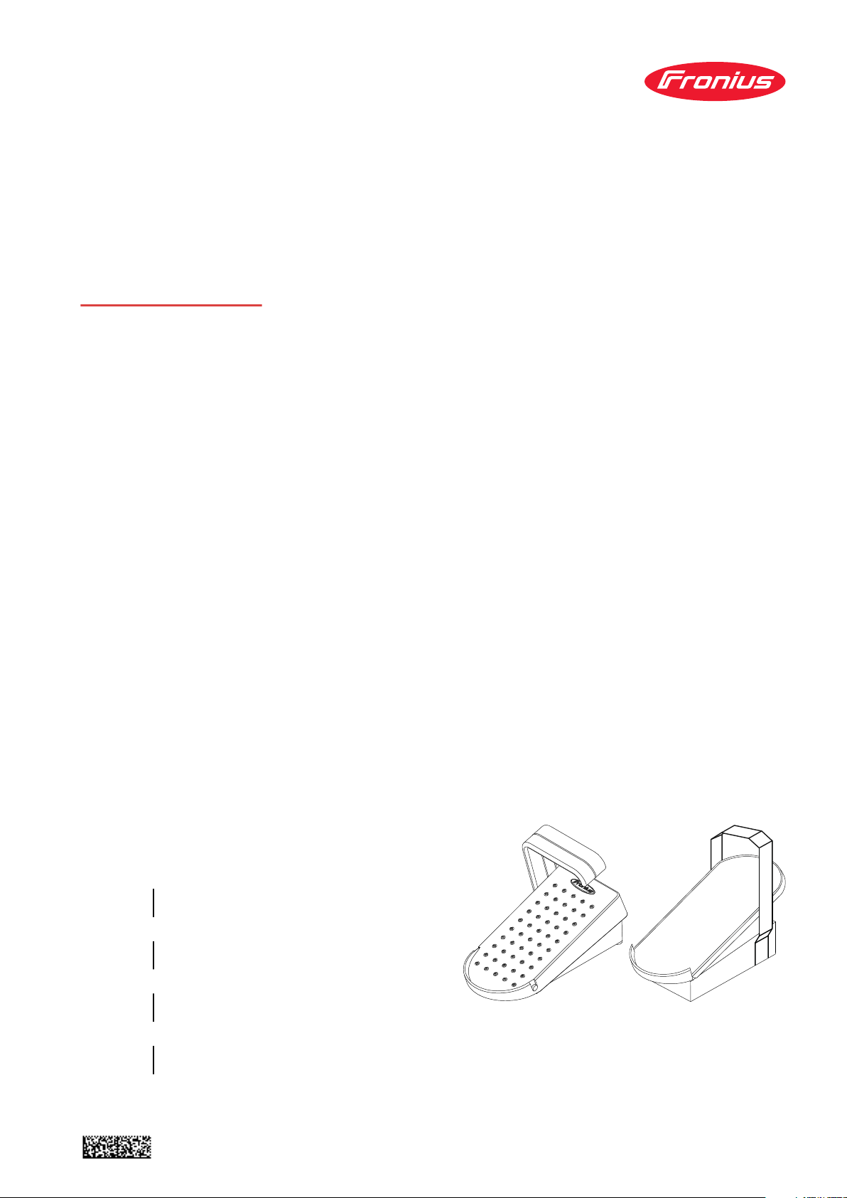
Fernbedienung TR 2200 F und TR 2200 FM
Produktkonzept
Fernbedienung TR 2200 F und TR 2200 FM
Die Fernbedienungen TR 2200 F und TR 2200 FM ermöglichen ein einfaches Einstellen des Schweißstromes mittels Fußpedal. Die Hände bleiben frei. Dadurch
ist auch bei ständiger Schweißstrom-Korrektur eine ungestörte SchweißbrennerFührung sichergestellt.
DE
Systemvoraussetzungen
Fernbedienung
anschließen
Sind die Fernbedienungen TR 2200 F und TR 2200 FM angeschlossen, gilt der
mittels Einstellrad vorgegebene Schweißstrom als Maximalstrom. Der gesamte
Pedalweg entspricht dem Bereich vom minimalen Schweißstrom bis zum Maximalstrom. Insbesondere bei geringem Schweißstrom ist dadurch ein besonders
sensibles Dosieren möglich.
Der Betrieb der Fernbedienungen TR 2200 F und TR 2200 FM ist in Verbindung
mit folgenden Stromquellen möglich:
MagicWave1700 / 2200
-
TransTig 2200
-
WARNUNG!
Gefahr durch Fehlbedienung und fehlerhaft durchgeführte Arbeiten.
Schwere Personen- und Sachschäden können die Folge sein.
Alle in diesem Dokument beschriebenen Arbeiten und Funktionen dürfen
▶
nur von technisch geschultem Fachpersonal ausgeführt werden.
Dieses Dokument vollständig lesen und verstehen.
▶
Sämtliche Sicherheitsvorschriften und Benutzerdokumentationen dieses
▶
Gerätes und aller Systemkomponenten lesen und verstehen.
3
Page 4

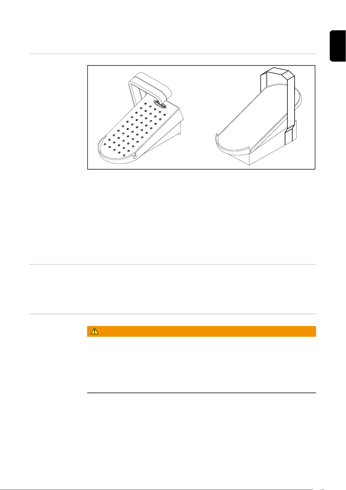
Anschlussbuchse LocalNet
Schweißbetrieb unterbrechen.
1
Kabel der Fernbedienung an der
2
Anschlussbuchse LocalNet (1) anstecken.
Schweißbetrieb wieder aufnehmen.
3
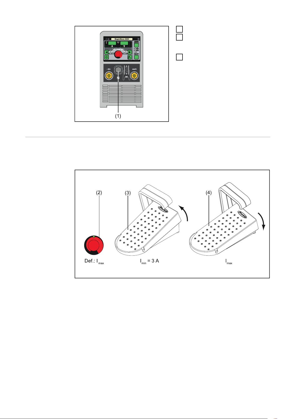
Schweißstrom
einstellen
Sind an der Anschlussbuchse LocalNet die Fernbedienungen TR 2200 F und TR
2200 FM angeschlossen, steht der mittels Einstellrad (2) eingestellte
Schweißstrom nur bei voll durchgetretenem Fußpedal (4) zur Verfügung.
Einstellrad und Fußpedal
Mittels Einstellrad (2) den maximalen Schweißstrom (I
-
Fußpedal nicht betätigt (3): Minimalstrom (I
-
Fußpedal voll durchgetreten (4): Maximalstrom (I
-
min
= 3 A)
max
max
)
) einstellen
Der Pedalweg entspricht einem kontinuierlichen Erhöhen des Schweißstromes.
4
Page 5

TR 2200 F and TR 2000 FM remote control unit
Product concept
TR 2200 F and TR 2200 FM remote control
The TR 2200 F and TR 2200 FM remote controls allow the welding current to be
easily adjusted with the aid of a foot pedal. The welder's hands remain free. This
means that, even when constantly correcting the welding current, uninterrupted
welding torch guidance is guaranteed.
EN
System requirements
Connecting the
remote control
If the TR 2200 F and TR 2200 FM remote controls are connected, the maximum
current is the welding current that was set using the adjusting dial. The total pedal travel corresponds to the range from the minimum welding current to the
maximum welding current. This allows for very sensitive adjustment, particularly
at low welding currents.
The TR 2200 F and TR 2000 FM remote control units can be operated in conjunction with the following power sources:
MagicWave1700 / 2200
-
TransTig 2200
-
WARNING!
Danger from incorrect operation and work that is not carried out properly.
This can result in serious personal injury and damage to property.
All the work and functions described in this document must only be carried
▶
out by technically trained and qualified personnel.
Read and understand this document in full.
▶
Read and understand all safety rules and user documentation for this device
▶
and all system components.
5
Page 6
LocalNet connection socket
Interrupt welding operation.
1
Plug the remote control cable into
2
the LocalNet connection socket
(1).
Resume welding operation.
3
Adjusting the
welding current
If the TR 2200 F and TR 2200 FM remote controls are connected to the LocalNet
connection socket, the welding current that was set using the adjusting dial (2) is
only available when the foot pedal (4) is fully depressed.
Adjusting dial and foot pedal
Use the adjusting dial (2) to set the maximum welding current (I
-
Foot pedal not actuated (3): Minimum current (I
-
Foot pedal fully depressed (4): Maximum current (I
-
min
= 3 A)
max
)
max
)
Depressing the pedal equates to continually increasing the welding current.
6
Page 7

Télécommande TR 2200 F et TR 2200 FM
Concept du produit
Commande à distance TR 2200 F et TR 2200 FM
Les commandes à distance TR 2200 F et TR 2200 FM permettent un réglage facile de l'intensité de soudage à l'aide d'une pédale. Les mains libres, il est possible
d'assurer un guidage de la torche sans accroc tout en corrigeant constamment
l'intensité de soudage.
FR
Conditions à
remplir par le
système
Raccorder la
commande à distance
Si les commandes à distance TR 2200 F et TR 2200 FM sont raccordées, l'intensité de soudage définie à l'aide de la molette de réglage est considérée comme
l'intensité maximale. La course de la pédale correspond à la plage d'intensité de
soudage, de la valeur minimale à la valeur maximale. Cela permet un dosage particulièrement sensible, notamment lorsque l'intensité de soudage est faible.
Le fonctionnement de les télécommandes TR 2200 F et TR 2200 FM est possible
avec les sources de courant suivantes:
MagicWave1700 / 2200
-
TransTig 2200
-
AVERTISSEMENT!
Danger dû à une erreur de manipulation et d'erreur en cours d'opération.
Cela peut entraîner des dommages corporels et matériels graves.
Toutes les fonctions et tous les travaux décrits dans le présent document
▶
doivent uniquement être exécutés par du personnel techniquement qualifié.
Ce document doit être lu et compris dans son intégralité.
▶
Lire et comprendre toutes les consignes de sécurité et la documentation uti-
▶
lisateur de cet appareil et de tous les composants périphériques.
7
Page 8

Connecteur LocalNet
Interrompre le soudage.
1
Brancher le câble de la commande
2
à distance sur le connecteur LocalNet (1).
Reprendre le soudage.
3
Régler l'intensité
de soudage
Si les commandes à distance TR 2200 F et TR 2200 FM sont raccordées au connecteur LocalNet, l'intensité de soudage paramétrée à l'aide de la molette de
réglage (2) n'est disponible que lorsque la pédale (4) est entièrement enfoncée.
Molette de réglage et pédale
À l'aide de la molette de réglage (2), régler l'intensité de soudage maximale
-
(I
)
max
Pédale non actionnée (3) : intensité minimale (I
-
Pédale entièrement enfoncée (4) : intensité maximale (I
-
min
= 3 A)
max
)
La course de la pédale correspond à une augmentation constante de l'intensité
de soudage.
8
Page 9

Zdalne sterowanie TR 2200 F i TR 2200 FM
Koncepcja produktu
Zdalne sterowanie TR 2200 F i TR 2200 FM
Moduły zdalnego sterowania TR 2200 F i TR 2200 FM umożliwiają łatwą regulację
prądu spawania za pomocą pedału nożnego. Nie trzeba przy tym używać rąk. Zapewnia to niezakłócone prowadzenie palnika spawalniczego również w przypadku
konieczności stałej korekty prądu spawania.
PL
Wymagania systemowe
Podłączanie
zdalnego sterowania
Jeżeli podłączone jest zdalne sterowanie TR 2200 F i TR 2200 FM, prąd spawania
ustawiony za pomocą pokrętła obowiązuje jako prąd maksymalny. Cała droga pedału odpowiada zakresowi od minimalnego do maksymalnego prądu spawania. W
szczególności, w przypadku niskiego prądu spawania jest dzięki temu możliwe
wyjątkowo dokładne dozowanie.
Eksploatacja zdalnego sterowania TR 2200 F i TR 2200 FM jest możliwa w
połączeniu z następującymi źródłami prądu spawalniczego:
MagicWave1700 / 2200
-
TransTig 2200
-
NIEBEZPIECZEŃSTWO!
Niebezpieczeństwo wskutek błędów obsługi i nieprawidłowego wykonywania
prac.
Skutkiem mogą być poważne uszczerbki na zdrowiu i straty materialne.
Wszystkie prace i funkcje opisane w tym dokumencie mogą wykonywać tylko
▶
technicznie przeszkoleni pracownicy.
Przeczytać i zrozumieć cały niniejszy dokument.
▶
Przeczytać i zrozumieć wszystkie przepisy dotyczące bezpieczeństwa i doku-
▶
mentację użytkownika niniejszego urządzenia i wszystkich komponentów systemu.
9
Page 10

Gniazdo przyłączeniowe LocalNet
Przerwać pracę.
1
Podłączyć kabel zdalnego sterowa-
2
nia do przyłącza LocalNet (1).
Wznowić pracę.
3
Ustawianie
prądu spawania
Jeżeli do przyłącza LocalNet są podłączone moduły zdalnego sterowania TR 2200
F i TR 2200 FM, prąd spawania ustawiony za pomocą pokrętła (2) jest dostępny
dopiero przy pełnym naciśnięciu pedału nożnego (4).
Pokrętło i pedał nożny
Za pomocą pokrętła (2) ustawić maksymalny prąd spawania ( I
-
Pedał nożny nie jest naciśnięty (3): prąd minimalny (I
-
Pedał nożny naciśnięty do końca (4): prąd maksymalny (I
-
min
= 3 A).
max
)
max
).
10
Droga pedału odpowiada ciągłemu zwiększaniu prądu spawania.
Page 11

PL
11
Page 12

 Loading...